1
Model 500
Gas Chromatograph
Hardware Reference Manual
Applies to Both
Daniel Danalyzer Model 500
Rosemount Analytical Model 500
Part Number 3-9000-537
Revision K
JULY 2010
Model 500 Gas Chromatograph
System Reference Manual
NOTICE
DANIEL MEASUREMENT AND CONTROL, INC.
AND ROSEMOUNT ANALYTICAL
(COLLECTIVELY, “SELLER”) SHALL NOT BE LIABLE FOR TECHNICAL OR EDITORIAL ERRORS IN
THIS MANUAL OR OMISSIONS FROM THIS MANUAL. SELLER MAKES NO WARRANTIES,
EXPRESSED OR IMPLIED, INCLUDING THE IMPLIED WARRANTIES OF MERCHANTABILITY AND
FITNESS FOR A PARTICULAR PURPOSE WITH RESPECT TO THIS MANUAL AND, IN NO EVENT,
SHALL SELLER BE LIABLE FOR ANY SPECIAL OR CONSEQUENTIAL DAMAGES INCLUDING,
BUT NOT LIMITED TO, LOSS OF PRODUCTION, LOSS OF PROFITS, ETC.
PRODUCT NAMES USED HEREIN ARE FOR MANUFACTURER OR SUPPLIER IDENTIFICATION
ONLY AND MAY BE TRADEMARKS/REGISTERED TRADEMARKS OF THESE COMPANIES.
THE CONTENTS OF THIS PUBLICATION ARE PRESENTED FOR INFORMATIONAL PURPOSES
ONLY, AND WHILE EVERY EFFORT HAS BEEN MADE TO ENSURE THEIR ACCURACY, THEY
ARE NOT TO BE CONSTRUED AS WARRANTIES OR GUARANTEES, EXPRESSED OR IMPLIED,
REGARDING THE PRODUCTS OR SERVICES DESCRIBED HEREIN OR THEIR USE OR
APPLICABILITY. WE RESERVE THE RIGHT TO MODIFY OR IMPROVE THE DESIGNS OR
SPECIFICATIONS OF SUCH PRODUCTS AT ANY TIME.
SELLER DOES NOT ASSUME RESPONSIBILITY FOR THE SELECTION, USE OR MAINTENANCE
OF ANY PRODUCT. RESPONSIBILITY FOR PROPER SELECTION, USE AND MAINTENANCE OF
ANY SELLER PRODUCT REMAINS SOLELY WITH THE PURCHASER AND END-USER.
DANIEL AND THE DANIEL LOGO ARE REGISTERED TRADEMARKS OF DANIEL MEASUREMENT
AND CONTROL, INC. ROSEMOUNT AND THE ROSEMOUNT ANALYTICAL LOGO ARE
REGISTERED TRADEMARKS OF ROSEMOUNT ANALYTICAL. THE EMERSON LOGO IS A
TRADEMARK AND SERVICE MARK OF EMERSON ELECTRIC CO.
COPYRIGHT © 2010 BY DANIEL MEASUREMENT AND CONTROL, INC., HOUSTON, TEXAS,
U.S.A.
All rights reserved. No part of this work may be reproduced or copied in any form or by any
means - graphic, electronic, or mechanical — without first receiving the written permission of
Daniel Measurement and Control, Inc. Houston, Texas, U.S.A.
WARRANTY
1. LIMITED WARRANTY: Subject to the limitations contained in Section 2 herein and except as
otherwise expressly provided herein, Daniel Measurement and Control, Inc. and Rosemount
Analytical, (collectively“Seller”) warrants that the firmware will execute the programming
instructions provided by Seller, and that the Goods manufactured or Services provided by Seller
will be free from defects in materials or workmanship under normal use and care until the
expiration of the applicable warranty period. Goods are warranted for twelve (12) months from
the date of initial installation or eighteen (18) months from the date of shipment by Seller,
whichever period expires first. Consumables and Services are warranted for a period of 90 days
from the date of shipment or completion of the Services. Products purchased by Seller from a
third party for resale to Buyer ("Resale Products") shall carry only the warranty extended by the
original manufacturer. Buyer agrees that Seller has no liability for Resale Products beyond making
a reasonable commercial effort to arrange for procurement and shipping of the Resale Products. If
Buyer discovers any warranty defects and notifies Seller thereof in writing during the applicable
warranty period, Seller shall, at its option, promptly correct any errors that are found by Seller in
the firmware or Services, or repair or replace F.O.B. point of manufacture that portion of the
Goods or firmware found by Seller to be defective, or refund the purchase price of the defective
portion of the Goods/Services. All replacements or repairs necessitated by inadequate
maintenance, normal wear and usage, unsuitable power sources, unsuitable environmental
conditions, accident, misuse, improper installation, modification, repair, storage or handling, or
any other cause not the fault of Seller are not covered by this limited warranty, and shall be at
Buyer's expense. Seller shall not be obligated to pay any costs or charges incurred by Buyer or
any other party except as may be agreed upon in writing in advance by an authorized Seller representative. All costs of dismantling, reinstallation and freight and the time and expenses of
Seller's personnel for site travel and diagnosis under this warranty clause shall be borne by Buyer
unless accepted in writing by Seller. Goods repaired and parts replaced during the warranty
period shall be in warranty for the remainder of the original warranty period or ninety (90) days,
whichever is longer. This limited warranty is the only warranty made by Seller and can be
amended only in a writing signed by an authorized representative of Seller. Except as otherwise
expressly provided in the Agreement, THERE ARE NO REPRESENTATIONS OR WARRANTIES OF
ANY KIND, EXPRESSED OR IMPLIED, AS TO MERCHANTABILITY, FITNESS FOR PARTICULAR
PURPOSE, OR ANY OTHER MATTER WITH RESPECT TO ANY OF THE GOODS OR SERVICES. It
is understood that corrosion or erosion of materials is not covered by our guarantee.
2. LIMITATION OF REMEDY AND LIABILITY: SELLER SHALL NOT BE LIABLE FOR DAMAGES
CAUSED BY DELAY IN PERFORMANCE. THE SOLE AND EXCLUSIVE REMEDY FOR BREACH OF
WARRANTY HEREUNDER SHALL BE LIMITED TO REPAIR, CORRECTION, REPLACEMENT OR
REFUND OF PURCHASE PRICE UNDER THE LIMITED WARRANTY CLAUSE IN SECTION 1
HEREIN. IN NO EVENT, REGARDLESS OF THE FORM OF THE CLAIM OR CAUSE OF ACTION
(WHETHER BASED IN CONTRACT, INFRINGEMENT, NEGLIGENCE, STRICT LIABILITY, OTHER
TORT OR OTHERWISE), SHALL SELLER'S LIABILITY TO BUYER AND/OR ITS CUSTOMERS
EXCEED THE PRICE TO BUYER OF THE SPECIFIC GOODS MANUFACTURED OR SERVICES
PROVIDED BY SELLER GIVING RISE TO THE CLAIM OR CAUSE OF ACTION. BUYER AGREES
THAT IN NO EVENT SHALL SELLER'S LIABILITY TO BUYER AND/OR ITS CUSTOMERS EXTEND
TO INCLUDE INCIDENTAL, CONSEQUENTIAL OR PUNITIVE DAMAGES. THE TERM
"CONSEQUENTIAL DAMAGES" SHALL INCLUDE, BUT NOT BE LIMITED TO, LOSS OF
ANTICIPATED PROFITS, LOSS OF USE, LOSS OF REVENUE AND COST OF CAPITAL.
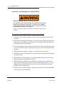
IMPORTANT INSTRUCTIONS
•
Read all instructions prior to installing, operating, and servicing this product.
•
Follow all warnings, cautions, and instructions marked on and supplied with this product.
•
Inspect the equipment packing case and if damage exists, notify your local carrier for
liability.
•
Open the packing list and carefully remove equipment and spare or replacement parts
from the case. Inspect all equipment for damage and missing parts.
•
If items are damaged or missing, contact the manufacturer at 1 (713) 827-6314 for
instructions about receiving replacement parts.
•
Install equipment as specified per the installation instructions and per applicable local and
national codes. All connections shall be made to proper electrical and pressure sources.
•
Ensure that all equipment doors are closed and protective covers are in place, except
when maintenance is being performed by qualified persons, to prevent personal injury.
•
Use of this product for any purpose other than its intended purpose may result in property
damage and/or serious injury or death.
•
Before opening the flameproof enclosure in a flammable atmosphere, the electrical
circuits must be interrupted.
•
Repairs must be performed using only authorized replacement parts as specified by the
manufacturer. Use of unauthorized parts can affect the product's performance and place
the safe operation of the product at risk.
•
When installing or servicing ATEX-certified units, the ATEX approval applies only to
equipment without cable glands. When mounting the flameproof enclosures in a
hazardous area, only flameproof cable glands certified to IEC 60079-1 must be used.
•
Technical assistance is available 24 hours a day, 7 days a week by calling 1 (713) 8276314.
This page is intentionally left blank.
TABLE OF CONTENTS
DESCRIPTION
EQUIPMENT
DESCRIPTION
1.1
PURPOSE OF THIS MANUAL ..........................1-1
1.1.1
Section 1 Description ...................................1-1
1.1.2
Section 2 Equipment Description ....................1-1
1.1.3
Section 3 Installation and Startup...................1-1
1.1.4
Section 4 Operation......................................1-1
1.1.5
Section 5 Maintenance .................................1-2
1.1.6
Section 6 Recommended Spare Parts..............1-2
1.1.7
Appendices ..................................................1-2
1.2
INTRODUCTION............................................1-2
1.3
FUNCTIONAL DESCRIPTION...........................1-4
1.4
MODES OF OPERATION.................................1-6
1.4.1
User Interfaces .............................................1-6
1.4.2
Capabilities...................................................1-6
1.5
THEORY OF OPERATION ...............................1-7
1.5.1
The Analyzer Detector ...................................1-7
1.5.2
Data Acquisition ......................................... 1-10
1.5.3
Peak Detection ........................................... 1-11
1.5.4
Basic Analysis Computations ........................ 1-12
1.6
GLOSSARY ................................................ 1-16
2.1
SAMPLING SYSTEM......................................2-1
2.1.1
Sampling Point Location .................................2-2
2.1.2
Sample Volume and Flow Rate........................2-2
2.1.3
Sample Conditioning ......................................2-3
2.1.4
Contamination Precautions .............................2-3
2.1.5
Valving ........................................................2-3
2
TABLE OF CONTENTS
INSTALLATION AND
SETUP
Installation and Setup
Model 500
2.1.6
Calibration Gas ............................................. 2-4
2.2
ANALYZER................................................... 2-5
2.2.1
Physical Description ...................................... 2-5
2.2.2
Chromatograph Valves................................... 2-7
2.2.3
Detector Subsystem ...................................... 2-8
2.2.4
Analyzer Preamplifier Unit .............................. 2-9
2.2.5
Analyzer Specifications .................................. 2-9
2.2.6
Utility Gas Requirements .............................. 2-10
2.3
CONTROLLER ............................................. 2-10
2.3.1
Controller Hardware Configurations ............... 2-12
2.3.2
Optional Keypad and Display ........................ 2-25
2.3.3
Alarm Specifications.................................... 2-26
3.1
PRECAUTIONS AND WARNINGS .................... 3-3
3.1.1
Hazardous Environments ................................ 3-4
3.1.2
Power Source Wiring ..................................... 3-5
3.1.3
Signal Wiring ................................................ 3-6
3.1.4
Electrical and Signal Ground ........................... 3-8
3.1.5
Electrical Conduit ........................................ 3-10
3.1.6
Sample Systems Requirements ..................... 3-11
3.2
PREPARATION............................................ 3-12
3.2.1
Introduction................................................ 3-12
3.2.2
Site Selection ............................................. 3-13
3.2.3
Unpacking the Unit...................................... 3-14
3.2.4
Necessary Tools and Components ................. 3-15
3.2.5
Optional Tools and Components.................... 3-16
3.3
INSTALLING THE ANALYZER ....................... 3-18
3.3.1
Point-to-point Wiring Guide,
Analyzer-Controller ...................................... 3-18
JULY 2010
TABLE OF CONTENTS
Model 500
OPERATION FROM
LOCAL KEYPAD AND
DISPLAY
JULY 2010
3
3.3.2
Analyzer AC Power Wiring ........................... 3-26
3.3.3
Sample and Gas Lines.................................. 3-27
3.4
INSTALLING THE GC CONTROLLER .............. 3-30
3.4.1
Modbus Slave Address (COM ID) Setup ......... 3-30
3.4.2
Controller-Analyzer Wiring ............................ 3-35
3.4.3
Controller PC Wiring (Serial Connections) ....... 3-37
3.4.4
CPU and COM4A Serial Communications
Setups ....................................................... 3-45
3.4.5
Controller Printer Wiring ............................... 3-69
3.4.6
Discrete (Digital) I/O Wiring .......................... 3-71
3.4.7
Analog I/O Wiring........................................ 3-74
3.4.8
Controller AC Power Wiring .......................... 3-77
3.5
ANALYZER LEAK CHECKS AND PURGING FOR
FIRST CALIBRATION ................................... 3-78
3.5.1
Analyzer Leak Checks .................................. 3-78
3.5.2
Purging Carrier Gas Lines ............................. 3-80
3.5.3
Purging Calibration Gas Lines........................ 3-83
3.6
SYSTEM START-UP .................................... 3-85
4.1
INTERFACE COMPONENTS FOR LOCAL DATA
DISPLAY AND ENTRY....................................4-3
4.1.1
Light Emitting Diode (Led) Indicators................4-3
4.1.2
Liquid Crystal Display (LCD) ...........................4-4
4.1.3
Keypad ........................................................4-4
4.2
LOGGING ON TO VIEW OR EDIT DATA ...........4-6
4.2.1
First Time Log-On..........................................4-6
4.2.2
Subsequent Log-On .......................................4-7
4.2.3
Start / Halt an Auto Sequence Analysis............4-8
4.2.4
Editing Procedures....................................... 4-10
4.2.5
Validity Checks of Data Entries ..................... 4-11
Operation from Local Keypad and Display
4
TABLE OF CONTENTS
MAINTENANCE
Maintenance
Model 500
4.3
LOCAL DISPLAY MENUS ............................. 4-12
4.3.1
Main Menu ................................................. 4-14
4.3.2
Hardware Menu .......................................... 4-14
4.3.3
Operator Entries Menu ................................. 4-15
4.3.4
Alarms Menu .............................................. 4-16
4.3.5
Chromatogram Menu ................................... 4-16
4.3.6
GC Control Menu ........................................ 4-16
4.3.7
Data Records Menu ..................................... 4-17
4.3.8
Config Rpt - Maint. Log Menu ....................... 4-17
5.1
TROUBLESHOOTING AND REPAIR CONCEPT ... 5-2
5.2
ROUTINE MAINTENANCE............................... 5-3
5.2.1
Model 500 Maintenance Checklist................... 5-4
5.2.2
Routine Maintenance Procedures..................... 5-5
5.2.3
Contract Service ........................................... 5-5
5.3
LOCATING AND GAINING ACCESS TO EQUIPMENT
ELEMENTS ................................................... 5-5
5.3.1
Analyzer Electrical/Electronic Units .................. 5-5
5.3.2
Detector Elements, Heater Elements, Valves and
Columns ...................................................... 5-7
5.4
PRECAUTIONS FOR HANDLING PRINTED CIRCUIT
ASSEMBLIES ................................................ 5-7
5.5
SERVICE, TROUBLESHOOTING, AND REPAIR
INSTRUCTIONS ............................................ 5-8
5.5.1
Preamplifier ................................................ 5-10
5.5.2
Temperature Control.................................... 5-10
5.5.3
Decoder ..................................................... 5-10
5.5.4
Analyzer Troubleshooting Guide .................... 5-13
5.5.5
Chromatograph Valves................................. 5-22
5.5.6
Detector Bridge Balance ............................... 5-23
JULY 2010
TABLE OF CONTENTS
Model 500
5
5.5.7
Temperature Measurements ......................... 5-25
5.5.8
Measure Vent Flow (MV) ............................. 5-27
5.5.9
Analog Inputs ............................................. 5-27
5.6
GC CONTROLLER MAINTENANCE................. 5-28
5.6.1
GC Controller Access................................... 5-29
5.7
COMMUNICATIONS .................................... 5-30
5.7.1
GC Controller Address Change...................... 5-31
5.8
ANALOG INPUTS AND OUTPUTS ................. 5-31
5.8.1
Analog Output Dialog Description.................. 5-32
5.8.2
Changing a Variable..................................... 5-34
5.8.3
Changing the Bargraph................................. 5-35
5.8.4
Performing a Manual Calibration .................... 5-37
5.8.5
Performing an Automated Calibration............. 5-39
5.8.6
Analog Loopback Test Circuits...................... 5-41
5.8.7
Upgrading Analog Outputs ........................... 5-43
5.9
DISCRETE (DIGITAL) INPUTS AND OUTPUTS . 5-44
5.9.1
Digital Loopback Test Circuit ........................ 5-44
5.10
FUSE PROTECTION ..................................... 5-45
5.11
ANALYZER-CONTROLLER INTERCONNECT .... 5-46
5.11.1 Function Codes ........................................... 5-48
RECOMMENDED SPARE
PARTS
JULY 2010
6.1
ANALYZER SPARES ......................................6-1
6.1.1
Printed Circuit Card Assemblies (Analyzer) .......6-1
6.1.2
Electrical and Mechanical Assemblies (Analyzer)6-1
6.2
GC CONTROLLER SPARES .............................6-3
6.2.1
Printed Circuit Card Assemblies
(GC Controller)..............................................6-3
6.2.2
Electrical and Mechanical Components (GC
Controller) ....................................................6-3
Recommended Spare Parts
6
TABLE OF CONTENTS
APPENDIX A,
SUPPLEMENTAL
WIRING GUIDE - SERIAL
COMMUNICATIONS
APPENDIX B,
MANIFOLD FOR TWO
CARRIER GAS BOTTLES
TO GC SYSTEM
APPENDIX C, GUIDE TO
TRANSIENT
PROTECTION MODULES
Model 500
A.1
GC SERIAL PORT AND CABLE CONFIGURATIONS
FOR RS-232 .................................................A-1
A.2
RS-232 CONNECTION FROM GC CONTROLLER TO
PC...............................................................A-4
A.2.1
DB-9 Serial Port of GC to DB-9 Port of PC ........A-4
A.2.2
DB-9 Serial Port of GC to DB-25 Port of PC ......A-5
A.2.3
Phoenix Plug Port of GC to DB-9 Port of PC......A-6
A.2.4
Phoenix Plug Port of GC to DB-25 Port of PC....A-7
A.3
RS-232 CONNECTION FROM GC CONTROLLER TO
EXTERNAL MODEM ......................................A-8
A.3.1
DB-9 Serial Port of GC to DB-25 Port of
Modem ........................................................A-8
A.3.2
Phoenix Plug Port of GC to DB-25 Port of
Modem ........................................................A-9
A.4
EXAMPLE RS-422 CONNECTION FROM PC TO
GC ............................................................A-10
A.5
EXAMPLE RS-485 CONNECTION FROM PC TO
GC ............................................................A-12
A.6
JUMPER-BASED SERIAL CHANNEL
CONFIGURATIONS......................................A-15
B.1
ILLUSTRATION ............................................. B-2
B.2
INSTALLATION AND LINE PURGING................ B-3
B.3
REPLACING CARRIER CYLINDER .................... B-4
C.1
PURPOSE OF THE TRANSIENT PROTECTION
MODULES ....................................................C-1
C.2
PART APPLICATIONS, NUMBERS, AND
DESCRIPTIONS .............................................C-2
Appendix A, Supplemental Wiring Guide - Serial Communications
JULY 2010
TABLE OF CONTENTS
Model 500
7
C.3
TROUBLESHOOTING TRANSIENT PROTECTION
MODULES ....................................................C-4
F.1
HALT CURRENT ANALYSIS AND POWER
DOWN ......................................................... F-1
F.2
NOTE EXISTING WIRING CONNECTIONS TO
2251 ........................................................... F-2
F.3
REMOVE CABLES, REPLACE CONTROLLER, AND
RECONNECT ................................................ F-5
G.1
2350A CPU ASSEMBLY INTRODUCTION ........ G-1
G.2
CONVERSION PROCESS ............................... G-2
G.3
BASIC 2350A CONFIGURATION .................... G-7
G.4
2350A OPTIONS.......................................... G-9
G.4.1
The COM4A Board ....................................... G-9
G.5
TO ADD A MODEM .....................................G-12
G.6
TO ADD AN ETHERNET CARD......................G-15
H.1
INTRODUCTION........................................... H-2
H.2
REMOVING THE OLD CPU CARD ................... H-4
H.3
INSTALLING THE NEW CPU BOARD............... H-6
H.4
INSTALLING A KEYBOARD AND DISPLAY WITH
COM4A BOARD........................................... H-7
APPENDIX D, INTERNAL
MODEM FOR GC
CONTROLLER
APPENDIX E, SETTING
SOLENOID PURGE
FLOWS
APPENDIX F,
UPGRADING FROM
2251 TO 2350A GC
CONTROLLER
APPENDIX G, 2350 TO
2350A CPU RETROFIT
INSTRUCTIONS
APPENDIX H, 2350A
(LX-800) CPU RETROFIT
INSTRUCTIONS
JULY 2010
Appendix D, Internal Modem for GC Controller
8
TABLE OF CONTENTS
Model 500
H.5
INSTALLING A KEYBOARD AND DISPLAY
WITHOUT COM4A BOARD.............................H-9
H.6
RETROFITTING THE ANALOG BOARD ...........H-11
H.6.1
Identifying your Analog Board .......................H-11
H.6.2
Installing a New Analog Board ......................H-13
H.7
REASSEMBLING THE 2350A ........................H-13
APPENDIX F, SHIPPING
AND LONG-TERM
STORAGE
RECOMMENDATIONS
ADDENDUM 1
ADDENDUM 2
Appendix F, Shipping and long-term storage recommendations
JULY 2010
DESCRIPTION
1.1
PURPOSE OF THIS MANUAL
This manual (P/N 3-9000-537) is intended as a user's guide to accompany
the Model 500 gas chromatograph.
For software operation instructions, see the MON2000 Software for
Gas Chromatographs User Manual (P/N 3-9000-522)
This manual provides the following information:
1.1.1
Section 1 Description
• A general description of the Model 500 gas chromatograph (GC) and
its components, their configurations and functions.
• A brief description of the GC's software, user interface, and
capabilities.
• Introduction to GC theory of operation and terminology.
1.1.2
Section 2 Equipment Description
• Guidelines for sampling system and gas connections.
• Descriptions of Analyzer subsystems and components.
• Descriptions of GC Controller subsystems and components.
1.1.3
Section 3 Installation and Startup
Instructions for installing the GC hardware.
1.1.4
Section 4 Operation
Instructions for operating the GC by means of its built-in keypad and
liquid crystal display (LCD), if provided.
1-2
1.1.5
Description
Model 500 Gas Chromatograph
Section 5 Maintenance
• Instructions for regular maintenance and care of the GC hardware.
• Instructions for troubleshooting, repair, and service of the GC
hardware.
1.1.6
Section 6 Recommended Spare Parts
List of boards, valves, and other components suggested as spare parts.
1.1.7
Appendices
Appendices with additional, helpful reference materials and drawings.
1.2
INTRODUCTION
The Model 500 GC is a high-speed gas chromatograph that is factory
engineered to meet specific field application requirements based on
typical stream composition and the anticipated concentration of the
components of interest. The Model 500 typically consists of three major
components, the Analyzer Assembly, the Controller, and the Sample
Conditioning System:
Analyzer Assembly (Model 500 Series) - Located near the sample tap.
The Analyzer includes GC columns, detectors, preamplifier, stream
switching valves, and solenoids. The Model 500 Analyzer is housed in a
National Electrical Manufacturers Association (NEMA) 7, National
Electrical Code (NEC) Class I, Division 1, Groups B, C, and D approved
enclosure, for use in a hazardous environment.
GC Controller - Located no further than 2000 feet (610 meters) away
from the Analyzer. The GC Controller includes electronics and ports for
signal processing, instrument control, data storage, personal computer
(PC) interface, and telecommunications. The GC Controller is available
in various enclosures and configurations, as follows:
Explosion Proof - NEMA 4X (weatherproof and corrosion resistant) and
NEMA 7, NEC Class I, Division 1, Groups B, C, and D approved
enclosure, for use in a hazardous environment. Available with or without
a built-in keypad and liquid crystal display (LCD).
Section 5 Maintenance
JULY 2010
Model 500 Gas Chromatograph
Description
1-3
Rack Mount - Suitable for use in a nonhazardous environment. Made
for mounting on a standard 19 inch rack. Available with or without a
built-in keypad and LCD.
Retrofit - Suitable for use in a nonhazardous environment. Made for
mounting on a 12-inch rack previously sold for 2251 GC Controller. The
Retrofit enclosure is not available with a built-in keypad and LCD
(therefore, a PC is required for operating).
Sample Conditioning System (SCS) - Located between the process
stream and the Analyzer sample inlet, usually mounted on the lower
portion of the Analyzer stand. The standard configuration SCS includes
a mounting plate, block (or shutoff) valves, and filters. Optionally, the
SCS can be configured with Genie® bypass filters, liquid shut-off valves,
and optional solenoids for stream switching: all of which can be enclosed
in an electric (heat tape design) oven.
In its standard configuration, the Model 500 Analyzer can handle up to
five streams: typically, four for sample and one for calibration. With an
optional stream switch assembly added, the Model 500 Analyzer can
switch up to twelve streams, maximum.
The GC Controller, is designed to be operated primarily from a personal
computer (PC) running the MON2000 Software package. This provides
the user with the greatest capability, ease-of-use, and flexibility. One PC
running MON2000 can connect with up to 32 gas chromatographs. The
PC is used to display chromatograms and reports, which can then be
stored as files on the PC, or printed from either the PC's or the GC's
printer.
Also, each individual GC can be operated from its built-in keypad and
LCD (if installed in that configuration); however, this method offers more
limited functions. Display of the chromatograms on the LCD is
accomplished in scrolling strip chart fashion.
Since neither the PC nor a normal printer can be placed in a hazardous
area, serial port and Modbus communications links are provided for
connecting the Model 500 Analyzer to the PC, other computers, printers,
chromatographs, and Controllers.
JULY 2010
INTRODUCTION
1-4
1.3
Description
Model 500 Gas Chromatograph
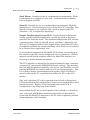
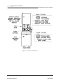
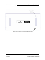
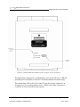
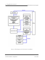
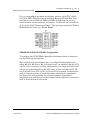
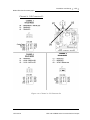
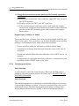
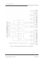
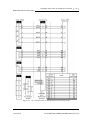
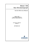
FUNCTIONAL DESCRIPTION
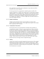
A functional block diagram of a typical Model 500 Analyzer installation is
shown in Figure 1-1. A sample of the gas to be analyzed is taken from the
process stream by a sample probe installed in the process line. The
sample passes through a sample line to the sample conditioning system
where it is filtered or otherwise conditioned. After conditioning, the
sample flows to the Analyzer for separation and detection of the
components of the gas.
The chromatographic separation of the sample gas into its components is
accomplished in the Analyzer in the following manner. A precise volume
of sample gas is injected into one of the unit's analytical columns. The
column contains a stationary phase (packing) that is either an active solid
(adsorption partitioning) or an inert solid support that is coated with a
liquid phase (absorption partitioning). The gas sample is moved through
the column by means of a mobile phase (carrier gas). Selective
retardation of the components of the sample takes place in the column
that causes each component to move through the column at a different
rate. This action separates the sample into its constituent gases and
vapors.
A detector located at the outlet of the analytical column senses the
elution of components from the column and produces electrical outputs
proportional to the concentration of each component. Outputs from the
Analyzer detectors are amplified in the Analyzer electronics, then
transmitted to the GC Controller for further processing. See also, Section
1.5, “Theory of operation” on page 7.
Output from the GC Controller is normally displayed on a remotely
located personal computer (PC) or a printer. Connection between the GC
Controller and the PC can be accomplished via a direct serial line, the
Modbus-compatible communication interface, modem or ethernet card.
Multiple chromatograms may be displayed on the PC monitor, and
compared or contrasted with separate color schemes. This allows a stored
chromatogram to be compared/contrasted with a current or another
stored chromatogram. This could be of great assistance when changing
parameters or isolating a problem.
FUNCTIONAL DESCRIPTION
JULY 2010
Model 500 Gas Chromatograph
Description
1-5
Use of a PC for configuration and troubleshooting procedures is essential
in most instances. Basic operations can also be performed from a keypad
and liquid crystal display that are built into certain versions of the GC
Controller. The PC may be remotely connected via telephone, radio,
ethernet or satellite communications. Once installed and configured, the
Model 500 Analyzer can operate independently for long periods of time.
Figure 1-1 Model 500 Analyzer Functional Block Diagram
JULY 2010
FUNCTIONAL DESCRIPTION
1-6
Description
1.4
MODES OF OPERATION
1.4.1
User Interfaces
Model 500 Gas Chromatograph
You have at least one, and optionally two, user interfaces from which to
operate the gas chromatograph (GC) system:
PC connected to the GC and running MON2000 - The PC
connected to the GC and running MON2000 offers the greatest
amount of capability and flexibility.
Find complete user instructions for MON2000 in the program's online
HELP screens and in the program user's manual, MON2000 Software
for Gas Chromatographs User Manual (P/N 3-9000-522).
or
The GC Controller's built-in keypad and LCD - The GC
Controller's built-in keypad and LCD offer essential startup and
operation functions. They are useful in a hazardous environment or if
no PC is available.
This feature is optional on all standalone models of the GC, except the
portable Compact BTU GC.
1.4.2
Capabilities
Individual gas chromatograph Controller functions that can be initiated
or controlled by the GC and its software, MON2000, are listed in the
MON2000 Software for Gas Chromatographs User Manual (P/N 3-9000522).
Modes of operation
JULY 2010
Model 500 Gas Chromatograph
1.5
Description
1-7
THEORY OF OPERATION
See also Section 1.6, “GLOSSARY” on page 16, for definitions
of some of the terminology used in the following explanations.
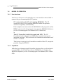
1.5.1
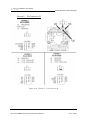
The Analyzer Detector
The Analyzer detector subsystem is a thermal conductivity detector that
consists of a balanced bridge network with heat-sensitive thermistors in
each leg of the bridge. Each thermistor is enclosed in a separate chamber
of the detector block. One thermistor is designated the reference element
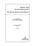
and the other the measurement element. A schematic diagram of the
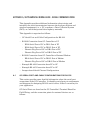
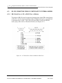
thermal conductivity detector is shown in Figure 1-2.
JULY 2010
Theory of operation
1-8
Description
Model 500 Gas Chromatograph
Figure 1-2 Schematic Diagram of Analyzer Detector Bridge
In the quiescent condition (prior to injecting a sample), both legs of the
bridge are exposed to pure carrier gas. In this condition, the bridge is
balanced and the bridge output is electrically nulled. (The bridge can be
balanced by the fine and coarse adjustment potentiometers located on the
preamplifier circuit board.)
The analysis begins when a fixed volume of sample is injected into the
column by operation of the sample valve. The sample is moved through
the column by the continuous flow of carrier gas. As successive
components elute from the column, the temperature of the measurement
element changes. The temperature change unbalances the bridge and
produces an electrical output proportional to the component
concentration. The differential signal developed between the two
thermistors is amplified by the preamplifier.
The Analyzer Detector
JULY 2010
Description
Model 500 Gas Chromatograph
1-9
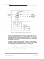
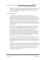
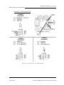
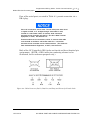
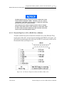
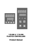
Figure 1-3 illustrates the change in detector electrical output during
elution of a component.
Figure 1-3 Detector output during component elution
1. Detector bridge balanced.
2. First component begins to elute from column and to be sensed by the
measurement thermistor.
3. Peak concentration of first component.
4. Second component begins to elute from column and to be sensed by the
measurement thermistor.
5. Peak concentration of second component.
In addition to amplifying the differential signal developed between the
detector's two thermistors, the preamplifier also supplies drive current to
the detector bridge. The preamplifier also supplies drive current to the
detector bridge. The voltage signal is converted to a 4 to 20-milliamp
(mA) current loop for transmission to the GC Controller. The signal is
proportional to the concentration of a component detected in the gas
sample. The preamplifier provides four different gain channels as well as
compensation for baseline drift. The signals from the preamplifier are
sent to the GC Controller for computation, recording on a printer, or
viewing on a PC monitor or LCD.
JULY 2010
The Analyzer Detector
1-10
1.5.2
Description
Model 500 Gas Chromatograph
Data Acquisition
Every second, exactly 40 equi-spaced data samples are taken for analysis
by the GC Controller (i.e., once every 25 milliseconds). Each data sample,
after having been precision-amplified, is subjected to a sixteen bit analog
to digital (A/D) conversion. The sampling frequency of 40 Hertz (Hz) was
chosen to reduce 60 Hz normal mode noise.
After each point on the chromatograph signal is sampled, the resulting
number is stored in a buffer area in the GC Controller's memory for
processing. During the analysis, only the last 256 data points are
available for processing. Because the data analysis is done as the signal
is sampled (in real-time), only a limited number of past data samples is
required to analyze any signal.
As a part of the data acquisition process, groups of incoming data samples
are averaged together before the result is stored to the Controller's
memory for processing. Non-overlapping groups of N samples are
averaged and stored, and thus reduce the effective incoming data rate to
40/N samples/second. For example, if N = 5, then a total of 40/5 or 6
(averaged) data samples are stored every second. The value for the
variable N is determined by the selection of a Peak Width parameter
(PW). The relationship is:
N = PW sec onds
where PW is given in seconds. All the various details in the analysis
process are independent of the value of N. Allowable values of N are 1 to
63, which corresponds to values of PW from 1 to 63 seconds.
The variable N is known as the integration factor. This term is used
because N determines how many points are averaged or integrated to
form a single value. The integration of data upon input, before storing,
serves two purposes. First, the statistical noise on the input signal is
reduced by the square root of N. In the case of N = 4, a noise reduction of
two would be realized. Secondly, the integration factor controls the
bandwidth of the chromatograph signal. It is necessary to match the
bandwidth of the input signal to that of the analysis algorithms in the GC
Data Acquisition
JULY 2010
Model 500 Gas Chromatograph
Description
1-11
Controller. This prevents small, short duration perturbations from being
recognized as true peaks by the program. It is therefore important to
choose a Peak Width corresponding to the narrowest peak in a group
under consideration.
1.5.3
Peak Detection
For normal area or peak height concentration evaluation, the
determination of a peak's start, peak point, and end is automatic. The
manual determination of start and end points is used only for area
calculations in the Forced Integration mode. Automatic determination of
peak onset or start is initiated whenever Integrate Inhibit is turned off.
Analysis is started in a region of signal quiescence and stability, such
that the signal level and activity can be considered as baseline values. It
is important that this be the case because this assumption is made by the
GC Controller.
Having initiated a peak search by turning Inhibit off, the GC Controller
performs a point by point examination of the signal slope. This is
achieved by using a digital slope detection filter which is a combination
low pass filter and differentiator. The output of this detector is
constantly compared to a system constant entered by the operator called
Slope Sensitivity. A default value of 8 is assumed if no entry is made.
Lower values make peak onset detection more sensitive, and higher
values make detection less sensitive. Higher values (20 to 100) would be
appropriate for noisy signals, e.g. high amplifier gain.
Peak termination is determined by the same application of this detector
to the signal, but in the reverse sense. Onset is defined where the
detector output exceeds the baseline constant, but termination is defined
subsequently where the detector output is less than the same baseline
constant.
Sequences of fused peaks are also automatically handled. This is done by
testing each termination point to see if the region immediately following
it satisfies the criteria of a baseline. A baseline region must have a slope
detector value less than the magnitude of the baseline constant for a
number of sequential points. When a baseline region is found, this
terminates a sequence of peaks.
JULY 2010
Peak Detection
1-12
Description
Model 500 Gas Chromatograph
A zero reference line for peak height and area determination is
established by extending a line from the point of the onset of the peak
sequence to the point of the termination. The values of these two points
are found by averaging the four integrated points just prior to the onset
point and just after the termination points, respectively. The zero
reference line will, in general, be non-horizontal, and thus compensates
for any linear drift in the system from the time the peak sequence starts
until it ends.
In a single peak situation, peak area is the area of the component peak
between the curve and the zero reference line. The peak height is the
distance from the zero reference line to the maximum point on the
component curve. The value and location of the maximum point is
determined from quadratic interpolation through the three highest points
at the peak of the discrete valued curve stored in the GC Controller.
For fused peak sequences, this interpolation technique is used both for
peaks as well as valleys (minimum points). In the latter case, lines are
dropped from the interpolated valley points to the zero reference line to
partition the fused peak areas into individual peaks. The use of
quadratic interpolation improves both area and height calculation
accuracy and eliminates the effects of variations in the integration factor
on these calculations.
For calibration, the GC Controller may average several analyses of the
calibration stream.
1.5.4
Basic Analysis Computations
Two basic analysis algorithms are included in the GC Controller. These
are:
• Area Analysis - Calculates area under component peak
• Peak Height Analysis - Measures height of component peak
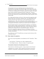
Concentration Analysis by Using Response Factor
Concentration calculations require a unique response factor foreach
component in an analysis. These response factors may be manually
entered by an operator or determined automatically by the system
Basic Analysis Computations
JULY 2010
Description
Model 500 Gas Chromatograph
1-13
through calibration procedures (with a calibration gas mixture that has
known concentrations).
Response factor calculation: (using the external standard)
Area n
ARF n = --------------Cal n
or
Ht n
HRF n = ----------Cal n
where:
ARFn
Area response factor for component n in area per mole percent (%).
HRFn
Height response factor for component n.
Arean
Area associated with component n in calibration gas.
Htn
Height associated with component n in mole percent in calibration gas.
Caln
Amount of component n in mole percent in calibration gas.
Calculated response factors are stored by the GC Controller for use in the
concentration calculations, and are printed out in the configuration and
calibration reports.
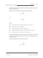
Average response factor is calculated as follows:
k
∑ RFi
RFAVG n =
JULY 2010
i-----------------= 1
k
Basic Analysis Computations
1-14
Description
Model 500 Gas Chromatograph
where:
RFAVGn
Area or height average response factor for component n.
Rfi
Area or height response factor for component n from the calibration run.
k
Number of calibration runs actually used to calculate the response
factors.
The percent deviation of new RF averages from old RF average is
calculated in the following manner:
RF new – RF old
% deviation = ------------------------------------ × 100
RFold
where the absolute value of % deviation for alarm has been previously
entered by the operator.
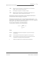
Concentration Calculations in Mole % without Normalization
Once response factors have been determined by the GC Controller or
entered by the operator, component concentrations are determined for
each analysis by using the following equations:
Area n
CONC n = --------------ARF n
or
Ht n
CONC n = -------------HRFn
where:
CONCn
Concentration of component n in mole percent.
Arean
Area of component n in unknown sample
Basic Analysis Computations
JULY 2010
Description
Model 500 Gas Chromatograph
ARFn
Response factor of component n calculated from area of calibration
sample. Units are area per mole percent.
Htn
Peak height of component n in unknown sample
HRFn
Response factor of component n calculated from peak height of calibration sample. Units are height per mole percent.
1-15
Note that the average concentration of each component will also be
calculated when data averaging is requested.
Component concentrations may be input through analog inputs 1 - 4 or
may be fixed. If a fixed value is used, the calibration for that component
is the mole % that will be used for all analyses.
Concentration Calculations with Normalization
CONC n
CONCN n = ---------------------------× 100
k
∑ CONCi
i=1
where:
CONCNn
Normalized concentration of component n in percent of total gas
concentration.
CONCn
Non-normalized concentration of component n in mole percent.
CONCi
Non-normalized concentration (in mole percent) from each of the k
components to be grouped into this normalization.
k
Number of components to be included in the normalization.
JULY 2010
Basic Analysis Computations
1-16
Description
Model 500 Gas Chromatograph
For additional information about other calculations that are
performed by the GC Controller and software, see the
MON2000 Software for Gas Chromatographs user manual (P/N
3-9000-522).
1.6
GLOSSARY
Auto Zero: Automatic zeroing of the preamplifier. May be entered into
the Controller to take place at any time during the analysis when either
the component is not eluting or the baseline is steady.
Chromatogram: A permanent record of the detector output. A
chromatograph is obtained from a PC interfaced with the detector output
through the GC Controller. A typical chromatogram displays all
component peaks, and gain changes. It may be viewed in color as it is
processed on a PC VGA display. Tick marks recorded on the
chromatogram by the GC Controller indicate where timed events take
place.
Component: Any one of several different gases that may appear in a
sample mixture. For example, natural gas usually contains the following
components: nitrogen, carbon dioxide, methane, ethane, propane,
isobutane, normal butane, isopentane, normal pentane, and hexanes
plus.
Condulet: Fitting resembling a pipe or a box with a removable cover for
access to electric conduits.
CTS: Clear to send (a serial port pin assignment).
DCD: Data carrier detect; see also, RLSD (a serial port pin assignment).
DSR: Data set ready (a serial port pin assignment).
DTR: Data terminal ready (a serial port pin assignment).
GLOSSARY
JULY 2010
Model 500 Gas Chromatograph
Description
1-17
Response Factor: Correction factor for each component as determined
by the calibration. See “Concentration Analysis by Using Response
Factor” on page 12 for more information.
Retention Time: The time (in seconds) that elapses between start of
analysis (0 seconds) and the sensing of the maximum concentration of
each component by the Analyzer detector.
RI: Ring indicator (a serial port pin assignment).
RLSD: Received line signal detect (a digital simulation of carrier detect);
see also, DCD (a serial port pin assignment).
RTS: Request to send (a serial port pin assignment).
RxD, RD, or SIN: Receive data, or signal in (a serial port pin
assignment).
TxD, TD, or SOUT: Transmit data, or signal out (a serial port pin
assignment).
JULY 2010
GLOSSARY
1-18
Description
Model 500 Gas Chromatograph
This page is intentionally left blank.
GLOSSARY
JULY 2010
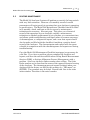
EQUIPMENT DESCRIPTION
This section provides descriptions of the various subsystems and
components that make up the Model 500 gas chromatograph. This
section is organized as follows:
• Sampling System
-
Sampling Point Location
Sample Volume and Flow Rate
Sample Conditioning
Contamination Precautions
Valving
Calibration Gas
• Analyzer
-
Physical Description
Chromatograph Valves
Detector Subsystem
Analyzer Preamplifier Unit
Analyzer Specifications
Utility Gas Requirements
• Controller
2.1
Controller Hardware Configurations
Optional Keypad and Display
Alarm Specifications
SAMPLING SYSTEM
A well designed, properly adjusted sampling system is essential to
optimum performance of any gas chromatograph. If a good sample is not
obtained for analysis, the whole purpose of the system is compromised.
The purpose of the sample handling system is not to transfer an exact
sample of process fluid to the chromatograph. Rather, the purpose is to
transfer a representative sample of the fluid--after it has been
2-2
Equipment description
Model 500 Gas Chromatograph
conditioned--that is compatible with chromatograph sample
requirements. This statement encompasses a big difference and is very
important to remember.
The Sample Conditioning System (SCS) is located between the process
stream and the Analyzer, and is usually mounted on the lower portion of
the Analyzer stand. It serves these purposes:
• Extracts final sample from the fast loop,
• Performs final filtration,
• Performs stream switching for a multi-stream Analyzer, and
• Adjusts the final pressure, temperature, and flow control on the
selected sample flowing to the sample valve.
The following points should be considered in selecting and installing a
sampling system.
2.1.1
Sampling Point Location
Gas samples must be representative of the process stream and must be
taken from a location where stratification or separation of components
does not occur. The sampling point should be as close as feasible to the
Analyzer.
2.1.2
Sample Volume and Flow Rate
An adequate response time for sample analysis requires that sample
volumes should generally be as small as possible, and the flow rate
between the sampling point and the Analyzer should be as high as
possible, consistent with accuracy. To minimize time lag and to prevent
back diffusion, dryers and filters in the sampling line should be as small
as possible. When long sampling lines cannot be avoided, flow velocity in
the line can be increased by decreasing the downstream pressure.
Typically, pressure is reduced at the sample point with a pressure
regulating sample probe. The input pressure to the Analyzer can be
adjusted between 10 and 20 pounds per square inch, gauge (psig).
Reducing the pressure at the sample point avoids the problem of heavy
liquid dropout in the sample line during cold weather. The flow rate in
Sampling Point Location
JULY 2010
Model 500 Gas Chromatograph
Equipment description
2-3
the sample line is set at 50 cubic centimeters (cc) per minute with the
restrictor valve at the Analyzer.
Use this general rule to approximate sample lag time caused by the
length of sample line. Sample line constructed of 1/8-inch tubing contains
approximately 1 cc of volume per foot. Therefore, with a flow rate of 50 cc
per minute, the lag time of the sample between the sample point and the
Analyzer is calculated by dividing the length of the line (in feet) by 50.
For example, the sample in a 100 foot sample line will take 2 minutes to
travel the length of the line.
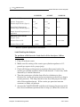
2.1.3
Sample Conditioning
Sample systems should contain at least one filter to remove solid
particles from the sample stream. Most applications require fine-element
filters upstream of the Analyzer.
2.1.4
Contamination Precautions
Several precautions are recommended to minimize the possibility of
contaminating samples. Except in special applications, filters should be
of either the ceramic or the porous metallic type to avoid the absorption
losses characteristic of fiber or paper filters. Pressure regulators and flow
controllers containing cork or felt filters or absorbent diaphragms should
not be used. Sampling lines for noncorrosive streams should be stainless
steel tubing and must be clean and free of grease. Lines must be pressure
tight to prevent diffusion of moisture or atmospheric gases into the
sample. Pipe threads should be dressed only with Teflon tape on pipe
threads and never with pipe thread compounds (dope).
2.1.5
Valving
A block valve should be installed immediately downstream of the sample
takeoff point to permit shutdown of the system for maintenance. Block
valves should be either needle valves or cocks of the proper material and
packing, and should be rated for the process line pressure. Tight seating
of all connections is essential.
JULY 2010
Sample Conditioning
2-4
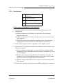
2.1.6
Equipment description
Model 500 Gas Chromatograph
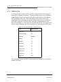
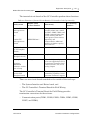
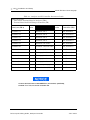
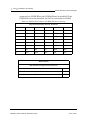
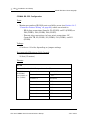
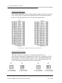
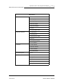
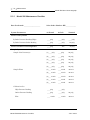
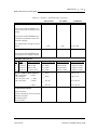
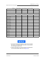
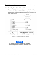
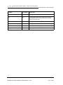
Calibration Gas
A calibration gas used for Process analysis should be blended of gases
specified as Primary Standards. Primary Standard gases are blended
using weights that are traceable to the National Institute of Standards
and Technology (N.I.S.T). The calibration gas should not have any
component that could drop out at the coldest temperature to which the
gas will be subjected. A typical C6+ blend for a temperature of zero
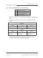
degrees Fahrenheit (0 °F) is listed in the following table. No dropout will
occur in this calibration gas if it is blended at a pressure below 250 psig.
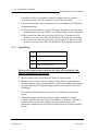
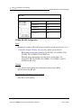
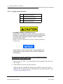
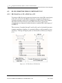
Table 2-1 Contents of Example Calibration Gas
Gas
Mole Percent
Nitrogen
2.5
Carbon dioxide
0.5
Methane
Balance
Ethane
5.0
Propane
1.0
Isobutane
0.3
N-butane
0.3
Neopentane
0.1
Isopentane
0.1
N-pentane
0.1
N-hexane
0.03
The sampling system should be carefully planned for the best chromatographic analyses.
Calibration Gas
JULY 2010
Model 500 Gas Chromatograph
2.2
ANALYZER
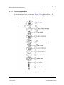
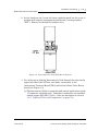
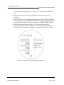
2.2.1
Physical Description
Equipment description
2-5
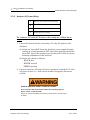
The Analyzer is physically divided into two major sections (see Figure 21). The upper heated section is temperature controlled and contains the
following components:
• Pneumatically actuated valves that control the flow of the sample and
carrier gases
• Detector elements
• Analytical columns
• A temperature-controlled heater block
The lower section consists of two explosion-proof housings that contain
printed-circuit assemblies for the following functions:
• Valve control
• Heater-block temperature control
• Detector drive
• Detector output signal preamplifier.
The Analyzer assembly, sample valves, and associated piping are
mounted in a self-supporting rack that may be placed at or near the
sample tap. Under most environmental conditions, the Analyzer
assembly requires no additional shelter.
JULY 2010
ANALYZER
2-6
Equipment description
Model 500 Gas Chromatograph
Figure 2-1 Analyzer Subsystems
Physical Description
JULY 2010
Equipment description
Model 500 Gas Chromatograph
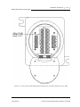
2.2.2
2-7
Chromatograph Valves
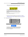
A chromatograph valve is shown in Figure 2-2 in exploded view. Its
pistons are pneumatically actuated in both switching directions by the
actuating assemblies located below the primary plate.
Figure 2-2 Chromatograph Valve
JULY 2010
Chromatograph Valves
2-8
Equipment description
Model 500 Gas Chromatograph
Primary Plate
The primary plate contains precisely machined internal passages that
enter and exit the valve at top ports, each of which is connected to the top
and/or bottom of the plate within the valve. The primary plate, which is
the only metallic element that comes in contact with the sample, is
isolated from the remainder of the valve by specially formulated
diaphragms.
GC valve should be torqued to 30 ft. lbs.
Actuating Subassemblies
Below the primary plate, pistons are operated by pneumatic pressure
applied to actuating diaphragms through ports in the base plate.
Operation
When pneumatic pressure is applied to the actuating diaphragms, the
pistons are actuated, thus forcing the sealing diaphragm against the
primary plate. This closes the passages that are connected at the bottom
of the plate. When pressure is removed, the pistons are free to move, and
flow is resumed through the passages.
2.2.3
Detector Subsystem
The operation of the Analyzer detector subsystem was previously
discussed in the "Theory of Operation" section of this manual.
Detector Subsystem
JULY 2010
Model 500 Gas Chromatograph
2.2.4
Equipment description
2-9
Analyzer Preamplifier Unit
The electrical output from the detector is amplified by the Analyzer
preamplifier unit. The preamplifier also supplies drive current to the
detector bridge. The voltage signal is converted to a 4 to 20-milliamp
(mA) current loop for transmission to the GC Controller. The signal is
proportional to the concentration of a component detected in the gas
sample. The preamplifier provides four different gain channels and
compensates for baseline drift. The signals from the preamplifier are
then sent to the GC Controller, where they provide the basis for analysis
computations and a chromatographic trace, or chromatogram.
2.2.5
Analyzer Specifications
Power Requirements: 120 volts, alternating current (VAC), +10/15VAC; 50 to 60 Hertz (Hz); single phase; 10 amperes (A) (maximum
during warmup) (additional 10 amps if unit has a Sample System Oven).
Ambient Temperature Range: -18 degrees Celsius ( C) to +55 C (0 F to
+130 F)
Humidity: 0 to 95 percent relative humidity, noncondensing
Vibration: Designed for mounting on process piping or other field
structures subject to normal process vibrations
National Electrical Code (NEC) Area Classification: Suitable for
NEC Class 1, Division 1, Groups B, C, and D
Rack Size:
• Height: 58 inches (147.3 centimeters [cm])
• Width: 18 inches (45.7 cm) maximum
• Depth: 18 inches (45.7 cm)
Weight: Approximately 125 pounds (56.8 kilograms [kg]), including
mounting hardware.
JULY 2010
Analyzer Preamplifier Unit
2-10
Equipment description
Model 500 Gas Chromatograph
Sample Requirements:
• Fluid Phase - Vapor
• Pressure - 15 to 30 psig, regulated to ±10 percent
• Flow Rate - 50 cc/min, typical
Analyzer Output Signal: Four different gain channels to provide a 4 to
20 mA signal to the Controller.
Transient Over Voltages Category: Installation Category (Over
Voltage Category II)
Cleaning requirements: Restricted to the 6-port valve (refer to “Valve
Cleaning” on page 5-22).
2.2.6
Utility Gas Requirements
Carrier Gas: Typically zero grade helium (99.995% pure, with less than
5 ppm water, and less than 0.5 ppm hydrocarbons).
Valve Actuation Gas: Typically zero grade, 99.995% pure helium at 115
psig. Consumption is 100cc per analysis cycle. Clean, dry air also may be
used for valve actuation. Carrier Gas and Valve Actuation Gas are
normally supplied from a common cylinder, since overall gas consumption
is minimal.
2.3
CONTROLLER
The Model 500 Controller is a microprocessor-based device that provides
the Model 500 Analyzer with highly accurate timing, precision
calculations, pertinent report generation, and an interface with other
devices. The Controller provides both analog outputs and a direct digital
link with output devices through RS-232C, RS-422, or RS-485 ports.
Volatile portions of the program are protected by a lithium battery
backup if power is lost or turned off at the unit.
Utility Gas Requirements
JULY 2010
Model 500 Gas Chromatograph
Equipment description
2-11
The Controller can be packaged for side-by-side use with the Model 500
Analyzer in a hazardous area, or for remote use in a safe area in a 19-inch
rack mounting. Also, a retrofit kit is available to replace the older model
GC Controller (Model 2251) used with the Model 500 Analyzer. The
retrofit kit is suitable for 12-inch rack mounting.
The Model 500 Controller can be linked directly to a PC by serial
connection or by a telecommunication link that uses Modbus protocol.
This provides the preferred method for operating the GC System.
Limited control of the GC System is also possible through a built-in
keypad and display, which are optional components of the explosionproof, hazardous environment GC Controller package. The local
alphanumeric keypad and display allow for maintenance and minor
adjustments in a hazardous environment.
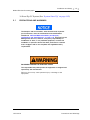
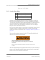
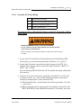
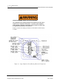
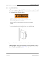
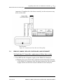
SERIOUS PERSONAL INJURY OR DEATH POSSIBLE
Do not operate a PC or printer in a hazardous environment.
Failure to observe all safety precautions could result in serious injury
or death.
The 19-inch rack mounted, 12-inch rack retrofit kit, and the explosionproof NEMA 4X, Groups B, C, and D, Controllers all operate identically.
JULY 2010
CONTROLLER
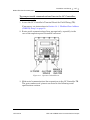
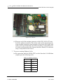
2-12
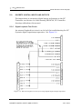
2.3.1
Equipment description
Model 500 Gas Chromatograph
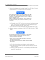
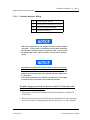
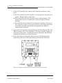
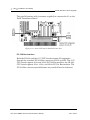
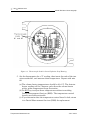
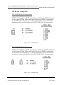
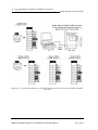
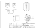
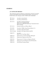
Controller Hardware Configurations
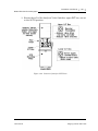
The Controller may be provided for hazardous area mounting, 19-inch
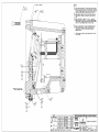
rack mounting, or used in a 12-inch rack retrofit kit. See Figure 2-3
through Figure 2-5. The unit consists of an STD-bus based computer and
related boards, including boards for terminating field wiring. The
enclosure for hazardous areas qualifies as flameproof (explosion-proof
NEMA 4X, Groups B, C, and D). Connections to the enclosure are
through one 2-inch (50mm) hole (reduced to 3/4 inch with bushing) and
two 1-inch (25 mm) conduit fittings located in the bottom. These accept
matching conduit or cable entries. Field connections are made through
explosion-proof conduit or flameproof glands.
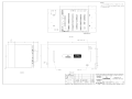
Figure 2-3 GC Controller, Explosion-Proof Version
Controller Hardware Configurations
JULY 2010
Model 500 Gas Chromatograph
Equipment description
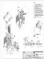
2-13
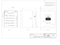
Figure 2-4 GC Controller, 19-inch Rack Mounted Version
JULY 2010
Controller Hardware Configurations
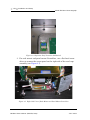
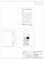
2-14
Equipment description
Model 500 Gas Chromatograph
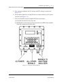
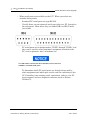
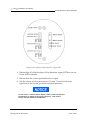
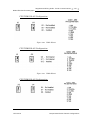
Figure 2-5 Model 2251 Retrofit Kit (12-inch rack) for the GC Controller
For operating a printer in a nonhazardous area at the GC site, a DB-25
parallel port is available on the GC's Terminal Board for field wiring.
For connecting a PC to the GC at the GC site (for setup, operation, or
maintenance in a nonhazardous area), a DB-9 serial port connector is
available on the Controller's front panel.
Controller Hardware Configurations
JULY 2010
Model 500 Gas Chromatograph
Equipment description
2-15
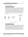
The STD-Bus Card Cage inside the GC Controller is equipped with two
cards. Card slots are preassigned so that cables can be consistently
routed. However, the COM4A board and the modem board (and Ethernet
card when using a 16-bit CPU board) can be piggy-backed in any order on
the CPU board. If a Radicom modem is used, it must be the top board in
the card cage assembly.
An optional stream switching assembly (with either AC or DC solenoids)
can be controlled by the GC Controller, allowing for switching up to 12
streams.
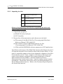
Analog Inputs and Outputs
The GC Controller can accommodate eight fully differential analog 4 to 20
mA input signals. Four of the analog inputs are used by the associated
Analyzer, and they are filtered with transient protection. The additional
four input ports provide the ability to accept signals from other
Analyzers, so that the analytical report of the chromatograph can include
other information on the gas stream, such as water or sulphur content.
Transient protection and shield terminations are available for these
inputs.
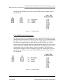
There is capability for a maximum of ten analog outputs. Two analog
outputs are available as standard components of the Controller; the other
eight analog outputs are optional. All ten analog outputs are current
type: 4-20 mA, not isolated. Also, all ten analog outputs can be calibrated
by the MON2000 software.
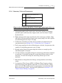
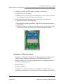
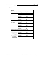
Digital Inputs and Outputs
The Controller has the capability of sixteen digital inputs used as follows:
5 - to read a Modbus address, as defined by DIP switch positions.
2 - to indicate presence and type of front panel as defined by switch
positions
1 - Spare
1 - temperature sensor input to shut off LCD backlight
1 - GC alarm, optically isolated, with transient protection
JULY 2010
Controller Hardware Configurations
2-16
Equipment description
Model 500 Gas Chromatograph
5 - stream flow alarms, optically isolated, with transient protection
1 - photocell detector, front panel backlight (night on, day off)
The Controller has the capability of 22 digital outputs used as follows:
6 - Analyzer control
8 - driver outputs for DC air solenoids (stream switching, 12 total
streams)
5 - alarms, optically isolated, with transient protection
3 - front panel indicators (green, yellow, red)
The digital transient-protected discrete outputs can furnish up to 50 mA.
If more current is required (up to 0.5A), a special transient protection
plug-in module should be installed (see Appendix C, this manual, for
transient protection module details).
Communications
There are 3 to 8 communication ports externally available, depending on
options package selected. The communications ports can use either RS232, RS-422, or RS-485 protocol, which, for the LX-800 CPU board, can be
set via MON20/20, and for the 6117 CPU board, must be set by Data
Interface Chips resident on the board.
The communications ports are configured at the factory, as specified by
the customer's communications requirements. The Modbus switch
positions are also normally set at the factory as specified by the customer.
If any changes need to be made in the field, refer to the drawings in the
rear of this manual.
Controller Hardware Configurations
JULY 2010
Model 500 Gas Chromatograph
Equipment description
2-17
Driver Outputs
The Controller has eight stream switch outputs, 120 mA continuous
current, which can be used to control optional AC or DC solenoid switch
boards. This increases stream switch capability from the standard
capability of four streams and 1 CAL to a maximum capability of twelve
streams.
The optional stream switching assembly (AC or DC solenoid
systems) has provisions for eight stream routes, but adding this
option has the net effect of adding only seven more stream routes
to the standard stream capacity of five (thus giving a total stream
capacity of twelve). The reason is, one of the Analyzer's standard
five stream routes becomes dedicated to the optional stream switch
assembly when the optional stream switch assembly is installed.
General Controller Specifications
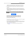
Power requirements (without current outputs): 63.25VA typical for
basic instrument
Voltage options:
• 115 VAC ±15 percent, 50 to 60 Hz @ 0.33 A
• 230 VAC ± 15 percent, 50 to 60 Hz @ 0.275 A
Temperature:
• Operating range: -18 C to 55 C (0 F to 131 F)
• Storage range: -40 C to 85 C (-40 F to 185 F)
Humidity: 0 to 95 percent relative humidity, noncondensing
JULY 2010
Controller Hardware Configurations
2-18
Equipment description
Model 500 Gas Chromatograph
Explosion-proof NEMA 4X, Groups B, C, and D, enclosure
dimensions:
• Height:13 inches
• Width:14 inches
• Depth: 14 inches
Rack mounted dimensions (standard 19-inch):
• Height:8.75 inches
• Width: 19 inches
• Depth: 8.5 inches
Retrofit kit enclosure dimensions (12-inch rack, "panel mount"):
• Height:8.5 inches
• Width:11 inches
• Depth:11 inches
Weight: Approximately 74 pounds for Explosion-Proof NEMA 4X,
Groups B, C, and D, version (not including stand)
Electrical/Mechanical Safety and Integrity - Certifications and
Classifications
Both the Analyzer and the GC Controller, when housed inside explosionproof enclosures, meet these certifications and classifications for
electrical and/or mechanical safety and integrity:
National Electrical Manufacturers Association (NEMA) 7 for National
Electrical Code (NEC) Class I, Division 1, Groups B, C, and D areas.
Meets Underwriters Laboratories Inc. (UL) 1203, "Explosion-Proof
and Dust-Proof Electrical Equipment of use in hazardous (Classified)
locations" for NEC Class I, Division 1, Groups B, C, and D, and
Canadian Standards Association (C.S.A.) 22.2 No. O-M1962, Part II
and C.S.A. 22.2 No. 30-M1986 for NEC Class I, Division 1, Groups B,
C, and D.
Controller Hardware Configurations
JULY 2010
Model 500 Gas Chromatograph
Equipment description
2-19
EEx d IIB T6 - Meets CENELEC EN 50 014, and EN 50 018,
"Electrical Apparatus for Potentially Explosive Atmospheres...", Parts
1 and 5, as flameproof for Group II, Subdivision B, Temperature Class
T6.
The GC Controller, when housed inside explosion-proof enclosure, meets
these certifications and classifications for electrical and/or mechanical
safety and integrity:
NEMA 4X - Meets NEMA 250, "Enclosures for Electrical Equipment
(1000 volts maximum)", for type 4X, Canadian Electrical Code, Part
II, Rule 2-400 1 d, and C.S.A. C22.2 No. 94-1967 as C.S.A. enclosure 4,
and International Electrotechnical Commission (IEC) 144, "Degrees of
protection of enclosures of Switchgear...", for IP 65.
Both the Analyzer, when housed inside explosion-proof enclosure, and the
GC Controller, when housed inside (a) the explosion-proof enclosure, (b)
the rack mount enclosure, or the retrofit enclosure, meet the Federal
Communications Commission (FCC) Part 15, Subparts A and B
classification for control against excessive radio frequency emissions.
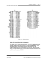
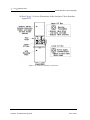
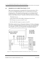
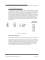
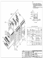
GC Controller Circuit Board List
The GC Controller circuit boards are inserted or attached to an STD-bus
card cage assembly. The Controller has two boards inserted into the card
cage, and two of the boards are attached to the card cage outside.
The 6117 CPU board has three optional piggy-back boards that can be
attached to it via the PC 104 bus:
• Modem
• COM4A serial ports 5, 6, 7, and 8
• Ethernet
JULY 2010
Controller Hardware Configurations
2-20
Equipment description
Model 500 Gas Chromatograph
There are two optional piggy-back boards that can be attached to the LX800 CPU board via the PC 104 bus:
• Modem
• COM4A serial ports 5, 6, 7, and 8
The LX-800's onboard Ethernet port can be used instead of the
optional Ethernet board, unless the LX-800 is installed with
application revision 3.99 or earlier (16 bit BOS), in which case, the
Ethernet board must be used.
onboard ethernet port
Controller Hardware Configurations
JULY 2010
Equipment description
Model 500 Gas Chromatograph
2-21
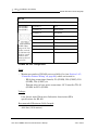
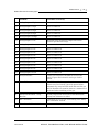
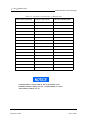
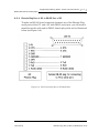
The inserted circuit boards of the GC Controller perform these functions:
Table 2-2 Functions of Inserted Circuit Boards, GC Controller Card Cage Assembly
Subsystems
32-bit CPU
microprocessor
board
Handle Label
or Part Number
LX800
See drawing
number...
Function(s)
Microprocessor; control of
parallel printer port; control
of COM1, COM2, COM3, and
COM4 communication ports;
system memory; RS-422
serial protocol; three timers,
digital I/O, and
CompactFlash. Additional
memory for higher capacity
data archives.
DE-20782
COM4A Board
(CPU Daughter
board)
Control of COM5 - COM8
BE-20767
Modem (CPU
Daughter board)
telephone modem
N/A
Analog*
Control of eight analog inputs
(4 for user applications and 4
for Analyzer-Controller interconnect) and two, six, or ten
analog outputs
BE-18044
PCM-NE 2000
Flexible, high-performance
networking capability; broad
spectrum of software support.
N/A
or
16-bit CPU
microprocessor
board
Analog I/O board
MCM/LPM-6117
[requires
MON2000
software, version
2.3 or later]
Ethernat Card
(16-bit CPU
daughter board)
There are two circuit boards attached to the outside of the card cage:
• The System Interface and Driver board, and
• The GC Controller's Terminal Board for Field Wiring.
The GC Controller's Terminal Board for Field Wiring provides
termination connections for these items:
• Communication ports (COM1, COM2, COM3, COM4, COM5, COM6,
COM7, and COM8),
JULY 2010
Controller Hardware Configurations
2-22
Equipment description
Model 500 Gas Chromatograph
• Analog inputs and outputs,
• Digital inputs and outputs,
• Controller-Analyzer interconnections,
• Parallel printer port, and
• Optional stream switching assemblies.
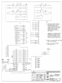
See drawing DE-20782 for an illustration of the GC Controller's
Terminal Board for Field Wiring.
The GC Controller's Terminal Board for Field Wiring also has sockets for
transient protection modules, and a 250 VAC, 2A fuse (5 x 20 mm) that
protects all of the boards from transient surges.
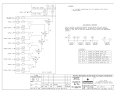
See Appendix C and drawing CE-18115 for a list of transient
suppression modules that are installed for various configurations of
the GC Controller and its communication, analog output, and
stream-switching options.
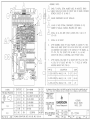
The System Interface and Driver board provides these functions:
• Drivers for switching the eight optional valve solenoids,
• Location for 8-position DIP switch to set the Modbus address,
• Opto-isolation circuits for the discrete inputs and outputs,
• Switching power supply and temperature shutdown circuit for the
LCD display,
• RS-232 to RS-422 conversion for the LCD display, and
• Voltage-to-current conversion for the analog outputs.
Controller Hardware Configurations
JULY 2010
Model 500 Gas Chromatograph
Equipment description
2-23
• Jumper for selecting driving voltage source for the 4-20 mA circuit.
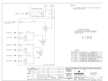
See drawing CE-18118 for an illustration of the System Interface
and Driver board.
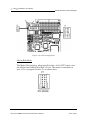
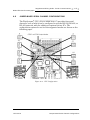
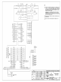
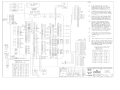
Also see Figure 2-6, which illustrates, through a block diagram, the
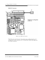
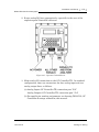
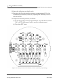
function and placement of the GC Controller circuit boards.
JULY 2010
Controller Hardware Configurations
2-24
Equipment description
Model 500 Gas Chromatograph
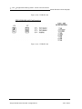
Figure 2-6 Block Diagram of the GC Controller Circuit Boards
Controller Hardware Configurations
JULY 2010
Model 500 Gas Chromatograph
2.3.2
Equipment description
2-25
Optional Keypad and Display
A keypad and liquid crystal display (LCD), optionally built into the
enclosure's front panel, are available for the explosion-proof and rack
mount versions of the GC Controller. (See Figure 2-5 for an illustration of
the explosion-proof Controller with optional keypad and LCD.) The builtin keypad and LCD are especially useful for the explosion-proof version.
They permit onsite display, control, and data entry at a GC Controller
that is situated in a hazardous environment. Note, however, that the
control capabilities offered through the built-in keypad and LCD are more
limited than those available through a PC connected to the GC
Controller.
For details on using the Controller's built-in keypad and LCD, see
“Operation from Local Keypad and Display” on page 4-1.
Keypad
The front panel keypad is an 18-Key data/function entry device arranged
so that the ALT key causes the lower key markings to be displayed/
entered. The designations marked on the top of the keys will be
displayed/entered when the ALT key is not pressed.
Display
The Controller display, measuring 5.5 x 2 inches, is capable of 8 lines by
41 characters. It is certified for use with a explosion-proof NEMA 4X,
Groups B, C, and D, enclosure. The display is capable of producing the
complete alphabet and numbers from the keypad. The video display on
the Controller may show a truncated (or curtailed) version of the displays
available at the PC. Although the keypad/display located at the
Controller site can do many of the functions that the PC software can do
remotely, any extensive operations are more conveniently performed
through MON2000 on the larger screen and keypad of a PC. A few
adjustments will be more conveniently accomplished at the Controller
site.
JULY 2010
Optional Keypad and Display
2-26
2.3.3
Equipment description
Model 500 Gas Chromatograph
Alarm Specifications
The GC Controller has the capacity for 36 alarms. There are also
operator defined alarms. Some of the alarms are active only if the
configuration of the Controller requires the function that is associated
with those alarms. Active alarms are shown in the ALARMS menu.
Status Indicators
Three colored LED status indicators are located at the side of the display
on the front panel. The indicators are arranged from yellow, green, and
red. When illuminated, the LED status indicators signify the following:
• Yellow LED: When illuminated, the Yellow LED indicates that an
out-of-tolerance value or an alarm condition was entered into the
Controller memory for printout with the analysis. The Controller
memory retains the alarm for printout until the operator clears the
alarm(s). This indicator is partially application controlled and may be
set at different out-of-tolerance levels with different applications.
• Green LED: When illuminated, the Green LED indicates that the
Controller is operating. If the green LED is illuminated and the Model
500 does not accept changes, a password lockout may have been
entered. If a password has been entered, the password must be reentered before the Model 500 program can be changed.
• Red LED: When illuminated, the Red LED indicates an out-oftolerance value or an alarm condition in the RUN mode that requires
operator action. Alarm contacts are closed under these conditions.
The Red LED is automatically turned off and contacts opened by the
Controller at the start of the next analysis.
Alarm Specifications
JULY 2010
Model 500 Gas Chromatograph
Equipment description
2-27
This page is intentionally left blank.
JULY 2010
Alarm Specifications
2-28
Equipment description
Alarm Specifications
Model 500 Gas Chromatograph
JULY 2010
INSTALLATION AND SETUP
Because the Model 500 Gas Chromatograph system is available in
different configurations, not all of the instructions in this section
may apply. In most cases, however, to install and set up a Model
500 Gas Chromatograph system, it is recommended that you follow
the instructions in nearly the same order as presented in this
manual. (Also see Table 3-1 for a summary of installation and setup
steps.)
This section provides instructions for installing and setting up the Model
500 Gas Chromatograph system. This section is organized as follows:
• Precautions and Warnings
- Hazardous Environments
- Power Source Wiring
- Signal Wiring
- Electrical and Signal Ground
- Electrical Conduit
- Sample Systems Requirements
• Preparation
-
Introduction
Site Selection
Unpacking the Unit
Necessary Tools and Components
Optional Tools and Components
• Installing the Analyzer
-
Point-to-Point Wiring Guide, Analyzer-Controller
Analyzer AC-Power Wiring
Sample and Gas Lines
3-2
Installation and Setup
Model 500 Gas Chromatograph
• Installing the GC Controller
-
Modbus Slave Address (COM ID) Setup
Controller-Analyzer Wiring
Controller-PC Wiring (Serial Connections)
CPU and COM4A Serial Communications Setups
Controller-Printer Wiring
Discrete (Digital) I/O Wiring
Analog I/O Wiring
Controller AC-Power Wiring
• Analyzer Leak Checks and Purging for First Calibration
-
Analyzer Leak Checks
Purging Carrier Gas Lines
Purging Calibration Gas Lines
• System Start-up
Summary of Installation and Setup Steps
1. Observe Precautions and Warnings (See “Precautions and Warnings”
on page 3-3)
2. Plan Site Location (See “Preparation” on page 3-12)
3. Obtain Supplies and Tools (See “Necessary Tools and Components” on
page 3-15)
4. Install Analyzer Wiring (See “Point-to-point Wiring Guide, AnalyzerController” on page 3-18)
5. Install Analyzer Sample & Gas Lines (See “Sample and Gas Lines” on
page 3-27)
6. Install GC Controller Wiring (See “Installing the GC Controller” on
page 3-30)
7. Perform Leak Checks (See “Analyzer Leak Checks” on page 3-78)
8. Purge Carrier Gas Lines (See “Purging Carrier Gas Lines” on page 380)
9. Purge Calibration Lines (See “Purging Calibration Gas Lines” on
page 3-83)
JULY 2010
Model 500 Gas Chromatograph
Installation and Setup
3-3
10. Start Up GC System (See “System Start-Up” on page 3-85)
3.1
PRECAUTIONS AND WARNINGS
The Analyzer and GC Controller, when housed inside explosionproof enclosures, meet the certifications and classifications
identified in “Electrical/Mechanical Safety and Integrity Certifications and Classifications” on page 2-18. Emerson Process
Management does not, however, accept any responsibility for
installations of these, or any attached equipment, in which the
installation or operation thereof has been performed in a manner
that is negligent and/or non-compliant with applicable safety
requirements.
EQUIPMENT DAMAGE OR PERSONAL INJURY
The responsible body shall operate the equipment as designed and
specified by the manufacturer.
Failure to do so may cause personal injury or damage to the
equipment.
JULY 2010
Precautions and Warnings
3-4
3.1.1
Installation and Setup
Model 500 Gas Chromatograph
Hazardous Environments
1
2
3
4
Observe Precautions and
Warnings
Plan Site Location
Obtain Supplies and Tools
Install Analyzer Wiring
Follow these precautions if installing or operating the Model 500
Analyzer and the GC Controller instrumentation in a hazardous
area:
1. Install and operate only the explosion-proof version of the GC
Controller in a hazardous area.
2. Do not operate in a hazardous area any printer or personal computer
(PC) that is connected to the GC Controller. To interface with a GC
Controller in a hazardous area, use the Controller's keypad and liquid
crystal display (LCD) that are built into the explosion-proof housing
as options. Or, alternatively, use a PC that is located in a
nonhazardous area and remotely connected to the GC Controller.
3. Ensure that field connections to the Analyzer and the GC Controller
are made through explosion-proof conduit or flameproof glands.
EQUIPMENT DAMAGE OR PERSONAL INJURY
Observe ALL applicable regulations when installing explosion-proof
GC units.
Failure to observe all regulations when installing explosion-proof GC
units may result in noncompliance, equipment damage or personal
injury.
Hazardous Environments
JULY 2010
Installation and Setup
Model 500 Gas Chromatograph
3-5
The explosion-proof GC Controller and Analyzer housings are certified for
use in locations where fire and explosion hazards may exist, specifically,
areas that are classified by the National Electronics Code (NEC) as Class
I, Division 1, Groups B, C, and D. However, other regulations apply. For
example, all interconnecting runs of cable through conduit must be sealed
at least 18 inches beyond the conduit's point of entry into certified
explosion-proof housing. Consult your company's policies and procedures
and other applicable requirements documents to determine appropriate
wiring and installation practices.
3.1.2
Power Source Wiring
1
2
3
4
Observe Precautions and
Warnings
Plan Site Location
Obtain Supplies and Tools
Install Analyzer Wiring
Follow these precautions when installing AC power source
wiring to the Model 500 Analyzer and the GC Controller instrumentation:
1. All wiring must conform to the National Electric Code, local state or
other jurisdiction, and company standards and practices.
2. Provide single-phase, three-wire, AC power at 115 or 230 volts AC, 5060 Hz.
3. A switch or circuit breaker shall be included in the building
installation in a safe area.
(a) The switch or circuit breaker is marked as the power disconnect
device.
(b) For Rack mount units, the power disconnect switch shall be in
close proximity to the equipment and easily accessible to the
operator.
4. Provide 20 ampere circuit breaker protection so that the major
components of the Model 500 Analyzer system–the Analyzer, the GC
JULY 2010
Power Source Wiring
3-6
Installation and Setup
Model 500 Gas Chromatograph
Controller, and any optionally installed sample oven or stream
switching devices--are all protected by one circuit breaker.
5. Use multi-stranded copper conductor wire according to the following
recommendations:
(a) For power feed distances up to 250 feet (76 meters), use wire size
American Wire Gauge (AWG) 14 (18 Metric Wire Gauge, stranded).
(b) For power feed distances 250 feet to 500 feet (76 meters to 152
meters), use wire size AWG 12 (25 Metric Wire Gauge, stranded).
(c) For power feed distances 500 feet to 1000 feet (152 meters to 305
meters), use wire size AWG 10 (30 Metric Wire Gauge, stranded).
3.1.3
Signal Wiring
1
2
3
4
Observe Precautions and Warnings
Plan Site Location
Obtain Supplies and Tools
Install Analyzer Wiring
Follow these general precautions for field wiring digital and
analog input/output (I/O) lines:
1. Metal conduit must be used for all process signal wiring.
2. Metal conduit used for process signal wiring must be grounded at
conduit support points (grounding the conduit at multiple points helps
prevent induction of magnetic loops between the conduit and cable
shielding).
3. Use suitable lubrication for wire pulls in conduit to prevent wire
stress.
4. All process signal wiring should be a single, continuous length
between field devices and the GC Controller. If, however, length or
conduit runs require that multiple wiring pulls be made, the
individual conductors must be interconnected with suitable terminal
blocks.
Signal Wiring
JULY 2010
Model 500 Gas Chromatograph
Installation and Setup
3-7
5. Use separate conduits for AC voltage and DC voltage circuits (see
Figure 3-1).
6. Do not place digital or analog I/O lines in same conduit as A-C power
circuits (see Figure 3-1).
7. Use only shielded cable for digital I/O line connections.
(a) Ground the shield at only one end.
(b) Shield-drain wires must not be more than two AWG sizes smaller
than the conductors for the cable.
Figure 3-1. Seperate Conduit Entries
JULY 2010
Signal Wiring
3-8
Installation and Setup
Model 500 Gas Chromatograph
8. When inductive loads (relay coils) are driven by digital output lines,
the inductive transients must be diode clamped directly at the coil.
9. Any auxiliary equipment wired to the GC Controller must have its
signal common isolated from earth/chassis ground.
Applicable to the digital and analog I/O lines connecting to the GC
Controller, including the Analyzer-Controller Interconnect lines: Any
loop of extra cable left for service purposes inside the GC Controller
explosion-proof housing must not be placed near the conduit entry
for AC power.
If the above precaution is not followed, the data and control signals
to and from the GC Controller can be adversely affected.
3.1.4
Electrical and Signal Ground
1
2
3
4
Observe Precautions and
Warnings
Plan Site Location
Obtain Supplies and Tools
Install Analyzer Wiring
Follow these general precautions for grounding electrical and
signal lines:
1. For shielded signal conducting cables, shield-drain wires must not be
more than two AWG sizes smaller than the conductors for the cable.
Shielding is grounded at only one end.
2. Metal conduit used for process signal wiring must be grounded at
conduit support points (Grounding the conduit at multiple points
helps prevent induction of magnetic loops between the conduit and
cable shielding).
3. A clamp type ground lug (color green) is located on the inside bottom
front of the GC Controller's case. Chassis ground conductors (color
Electrical and Signal Ground
JULY 2010
Model 500 Gas Chromatograph
Installation and Setup
3-9
code green) inside the Controller's enclosure should be stranded,
insulated copper wire. These device chassis ground conductors should
all be connected to the clamp type ground lug.
4. A clamp type ground lug is located on the outside of the GC
Controller's case at the rear of the lower right (facing the operator
panel) casting rib. This ground point should be connected to a copper
ground rod as described next.
5. A single-point ground (the outside case ground lug) must be connected
to a copper-clad, 10-foot long, 0.75" diameter steel rod, which is
buried, full-length, vertically into the soil as close to the equipment as
is practical. (Grounding rod not provided by Daniel Measurement
Services.)
6. Resistance between the copper-clad steel ground rod and the earth
ground must not exceed 25 Ohms.
7. The equipment-grounding conductors used between the GC Controller
and the copper-clad steel ground rod must be sized according to the
following specifications:
-length, 15 feet or less(4.6 meters) AWG 8, stranded, insulated copper wire
-length, 15 to 30 feet(4.6 to 9.1 meters) AWG 6, stranded, insulated copper wire
-length, 30 to 100 feet(9.1 to 30.5 meters) AWG 4, stranded, insulated copper wire
8. All inter-enclosure equipment-grounding conductors must be
protected by metal conduit.
9. External equipment, such as data printers, that are connected to the
GC Controller should be powered via isolation transformers to
minimize the ground loops caused by the internally shared safety and
chassis grounds.
JULY 2010
Electrical and Signal Ground
3-10
3.1.5
Installation and Setup
Model 500 Gas Chromatograph
Electrical Conduit
1
2
3
4
Observe Precautions and
Warnings
Plan Site Location
Obtain Supplies and Tools
Install Analyzer Wiring
Follow these general precautions for conduit installation:
1. Conduit cutoffs must be square. Cutoffs must be made by a cold
cutting tool, hacksaw, or by some other approved means that does not
deform the conduit ends or leave sharp edges.
2. All conduit fitting threads, including factory-cut threads, must be
coated with a metal-bearing conducting grease, such as Crouse-Hinds
STL or equivalent, prior to assembly.
3. Temporarily cap the ends of all conduit run runs immediately after
installation to prevent accumulation of water, dirt, or other
contaminants. If necessary, swab out conduits prior to installing the
conductors.
4. Install drain fittings at the lowest point in the conduit run; install
seals at the point of entry to the GC Controller's explosion-proof
housing to prevent vapor passage and accumulation of moisture.
5. Use liquid-tight conduit fittings, such as Myers® Scru-tite® or
similar, for conduit which is exposed to moisture.
When conduit is installed in hazardous areas (e.g., areas classified as
NEC Class I, Division 1, Groups B, C, and D), follow these general
precautions for conduit installation:
1. All conduit runs must have an explosion-proof sealing (potting) fitting
located within 18 inches (45.5 centimeters) distance from the conduit
entrance to explosion-proof housings.
2. The conduit installation must be vapor tight, with threaded hub
fittings, sealed conduit joints and gaskets on covers, or other approved
vapor-tight conduit fittings.
Electrical Conduit
JULY 2010
Installation and Setup
Model 500 Gas Chromatograph
3-11
EQUIPMENT DAMAGE OR PERSONAL INJURY
Consult your company's policies and procedures and other
applicable requirements documents to determine wiring and
installation practices that are appropriate for hazardous areas.
Failure to do so may cause personal injury or damage to equipment.
3.1.6
Sample Systems Requirements
1
2
3
4
Observe Precautions and
Warnings
Plan Site Location
Obtain Supplies and Tools
Install Analyzer Wiring
Observe the following guidelines for installing GC sample
systems:
Sample Line Length: If possible, avoid long sample lines. In case of a
long sample line, flow velocity can be increased by decreasing
downstream pressure and using by-pass flow via a speed loop.
Sample Line Tubing Material:
• Use stainless steel tubing for noncorrosive streams.
• Ensure tubing is clean and free of grease.
Dryers and Filters in Sample Line:
• Use small sizes to minimize time lag and prevent back diffusion.
JULY 2010
Sample Systems Requirements
3-12
Installation and Setup
Model 500 Gas Chromatograph
• Install a minimum of one filter to remove solid particles. Most
applications require fine-element filters upstream of the Analyzer.
• Do use ceramic or porous metallic type filters. Do not use cork or felt
filters.
Pressure Regulators and Flow Controllers in Sample Line: Do not
use types containing cork or felt filters, or absorbent diaphragms.
Pipe Threads, Dressing: Do use Teflon tape. Do not use pipe thread
compounds (dope).
Valving:
• Install a block valve downstream of sample takeoff point for
maintenance and shutdown.
• Block valve should be needle valve or cock valve type, of proper
material and packing, and rated for process line pressure.
3.2
PREPARATION
3.2.1
Introduction
Your Model 500 Analyzer was started and checked out before it left the
factory. Program parameters were installed in the system and
documented in the "PC Config Report" furnished with your Model 500
Analyzer.
Preparation
JULY 2010
Installation and Setup
Model 500 Gas Chromatograph
3.2.2
3-13
Site Selection
1
2
3
4
Observe Precautions and
Warnings
Plan Site Location
Obtain Supplies and Tools
Install Analyzer Wiring
Follow these guidelines for site selection:
1. Provide adequate access space for performing maintenance and
adjustments.
(a) Allow a minimum of 16 inches (41 cm) in front for enclosure
opening and access.
(b) Allow a minimum of 15 inches (38 cm) at the rear and left side for
case removal.
(c) If possible, mount the Analyzer components in a vertical stack
configuration; it provides the greatest operator convenience.
2. Install the Analyzer as close as possible to the sample stream.
3. Install the GC Controller no further than 2000 feet (610 meters) away
from the Analyzer.
(a) In a hazardous environment, you can install the explosion-proof
version of the GC Controller near the Analyzer, on either a 19-inch
or 12-inch rack.
(b) Observe the same recommendations for minimum clearance: 16
inches (41 cm) in front enclosure opening and access, and 15 inches
(38 cm) at the rear and left side for case removal.
(c) Refer to drawing CE-23878 in the Analyzer drawings addendum of
this manual.
4. Ensure that exposure to radio frequency (RF) interference is minimal.
JULY 2010
Site Selection
3-14
3.2.3
Installation and Setup
Model 500 Gas Chromatograph
Unpacking the Unit
1
2
3
4
Observe Precautions and
Warnings
Plan Site Location
Obtain Supplies and Tools
Install Analyzer Wiring
Observe the following checklist for unpacking the unit and
inspecting for damage:
1. Unpack the equipment:
(a) Model 500 series Analyzer
(b) GC Controller
2. Ensure that all documentation and software are included:
(a) This manual, the Model 500 Gas Chromatographs Hardware
Reference Manual, P/N 3-9000-537.
(b) The software manual, MON2000 Software for Gas
Chromatographs User Manual, P/N 3-9000-522.
(c) CD(s) with the MON2000 software program and GC Applications.
Installation and startup of the Model 500 Analyzer should proceed only if
all required materials are on hand and free from obvious defects. If any
parts or assemblies appear to have been damaged in shipment, first file a
claim with the carrier. Next, complete a full report of the nature and
extent of the damage and forward the report immediately to Daniel
Measurement Services (DMS), a division of Emerson Process
Management for further instructions. Include complete model number
information. Disposition instructions will be returned immediately by
Daniel Measurement Services. Refer to the Customer Repair Report in
the back of this manual.
Unpacking the Unit
JULY 2010
Installation and Setup
Model 500 Gas Chromatograph
3.2.4
3-15
Necessary Tools and Components
1
2
3
4
Observe Precautions and
Warnings
Plan Site Location
Obtain Supplies and Tools
Install Analyzer Wiring
Observe the following checklist of tools and components that you
will need for installing the Analyzer and GC Controller:
1. Chromatographic grade carrier gas: zero grade helium or nitrogen
(99.995% pure, with less than 5 ppm water, and less than 0.5 ppm
hydrocarbons).
2. High pressure dual-stage regulator for the carrier gas cylinder, high
side up to 3000 pounds per square inch, gauge (psig), low side capable
of controlling pressure up to 150 psig.
3. Calibration standard gas with correct number of components and
concentrations (see Section 2.1.6, “Calibration Gas” on page 4).
4. Dual-stage regulator for the calibration gas cylinder, low pressure side
capable of controlling pressure up to 30 psig.
5. Sample probe (fixture for procuring the stream, or sample gas for
chromatographic analysis).
6. 1/8-inch stainless steel (SS) tubing for connecting calibration standard
to analyzer, 1/4-inch SS tubing for connecting helium carrier to the
analyzer, 1/8-inch SS tubing for connecting stream gas to the
analyzer.
7. Miscellaneous Swagelok tube fittings, tubing benders and tubing
cutter.
8. 14 American Wire Gauge (AWG) (18 Metric Wire Gauge) or larger
electrical wiring and conduit to provide 115 or 230 volts AC, single
phase, 50 to 60 Hertz (Hz), from an appropriate circuit breaker and
power disconnect switch. (See previous guidelines in Section 3.1.2,
“Power Source Wiring” on page 5.)
JULY 2010
Necessary Tools and Components
3-16
Installation and Setup
Model 500 Gas Chromatograph
9. Liquid leak detector (SNOOP® or equivalent).
10. Digital volt-ohm meter with probe-type leads.
11. A flow measuring device such as Alltech Digital Flow Check™
Flowmeter.
3.2.5
Optional Tools and Components
1
2
3
4
Observe Precautions and
Warnings
Plan Site Location
Obtain Supplies and Tools
Install Analyzer Wiring
Observe the following checklist of tools and components you may
need for installing and using the GC System:
1. For operation in a nonhazardous area only: Printer and printer paper.
2. For operation in a nonhazardous area only: An IBM-compatible PC
and a "straight-through" serial cable connection between the external
DB-9 (female) serial ports of the GC Controller and a serial port of the
PC. (For details, see Section 3.4.3, “Controller PC Wiring (Serial
Connections)” on page 37.).
SERIOUS PERSONAL INJURY OR DEATH POSSIBLE
Do not operate a PC or printer in a hazardous environment.
Failure to observe all safety precautions could result in serious injury
or death.
Optional Tools and Components
JULY 2010
Model 500 Gas Chromatograph
Installation and Setup
3-17
If you are working in a hazardous area and need to perform routine
operations, use the optional keypad and LCD that are built into the
explosion-proof GC Controller. To make more significant changes,
however, use a remotely connected PC installed with MON2000. See
the MON2000 Software for Gas Chromatographs User Manual, P/N 39000-522, for more information.
Serial cable specifications:
• Straight-through serial cable with the following terminations:
• DB-9, maleconnects to GC Controller external serial port
• DB-9 or DB-25, femaleconnects to PC serial port
3. Interconnect Cable, P/N 6-4618-122, if not already installed between
the Analyzer and GC Controller. This is a shielded, computer and
communications grade, 15-conductor cable for making the thirteen
interconnections between the Analyzer and the GC Controller. This
cable, if not enclosed in conduit between the Analyzer and the GC
Controller, is suitable only for use in non-hazardous environments.
The cable must be run inside conduit for hazardous environments.
(For cable termination details, see Section 3.3.1, this manual.)
4. Direct Serial Connect Cable, P/N 3-2350-068, to connect the PC or an
external modem directly to the one of the GC Controller's serial ports
on the GC Controller's Terminal Board for Field Wiring (TB). This
cable comes in a customer-specified length. It is terminated with a
DB-9 female plug at one end, for connection to a PC or external
modem's serial port, and six exposed leads at the other end for
connection to the one of the GC Controller's serial ports on the TB.
(See Section 3.4.3.3 for directions on how to install this cable.)
5. Items necessary for connecting the GC Controller to an external
modem, a multi-drop serial network, or other type of remote data
transfer system (an example item might be an RS-232/RS-485
conversion box for long distance serial transmission).
JULY 2010
Optional Tools and Components
3-18
Installation and Setup
Model 500 Gas Chromatograph
3.3
INSTALLING THE ANALYZER
3.3.1
Point-to-point Wiring Guide, Analyzer-Controller
1
2
3
4
Observe Precautions and
Warnings
Plan Site Location
Obtain Supplies and Tools
Install Analyzer Wiring
This section applies only to GC systems which have not been
shipped "prewired." In most cases, the explosion-proof system will
already have had the Analyzer-Controller connections made. If your
system has already been wired, skip this section, and proceed to the
next section.
To make wiring connections between the Analyzer and the GC
Controller, follow these steps:
1. Disconnect all electrical power to both the Analyzer and the GC
Controller.
INSTALLING THE ANALYZER
JULY 2010
Model 500 Gas Chromatograph
Installation and Setup
3-19
2. At the Analyzer site, locate the lower explosion-proof box (its cover is
marked with original equipment manufacturer's catalog number
"XJT"). Remove its threaded Condulet cover.
Figure 3-2. Lower Explosion-Proof (XJT) Box at Analyzer
3. You will need to feed the Interconnect Cable through the inlet on the
upper left side of the XJT box, and make connections to the
interconnect Terminal Board (TB-4) which lies behind Valve Driver
board (see Figure 3-3).
(a) The Interconnect Cable is computer and control applications grade,
15-conductor, shielded cable. Individual conductors are stranded
tinned copper, #22 AWG-(7x30). (Also see description in Section
3.2.5, “Optional Tools and Components” on page 16.)
JULY 2010
Point-to-point Wiring Guide, Analyzer-Controller
3-20
Installation and Setup
Model 500 Gas Chromatograph
(b) Maximum length of Interconnect Cable (or, the maximum distance
between the Analyzer and the GC Controller) should not exceed
2000 feet (610 meters).
Figure 3-3. Behind the Condulet Cover is the Valve Driver Board, then TB-4
4. With the Condulet cover removed, loosen and remove the four (4)
thumbscrews that hold the Valve Driver board.
5. Carefully edge the Valve Driver board off the holding screws. Do not
disconnect the Valve Driver board from the cable; merely let the board
rest face down, secured by the cable (see Figure 3-4).
6. With the Analyzer TB-4 now exposed, connect thirteen of the
Interconnect Cable's fifteen leads to terminals 11 through 23. See
Table 3-1 and Figure 3-5 for purposes and destinations of leads. Also
see "CAUTION", step (6).
Point-to-point Wiring Guide, Analyzer-Controller
JULY 2010
Model 500 Gas Chromatograph
Installation and Setup
3-21
Figure 3-4. Valve Driver Board Resting Face Down from its Cable Allows Access to TB-4
JULY 2010
Point-to-point Wiring Guide, Analyzer-Controller
3-22
Installation and Setup
Model 500 Gas Chromatograph
Table 3-1. Analyzer and GC Controller Interconnect Leads
Board Acronyms:
• Interconnect Terminal Board of Analyzer (TB-4)
• Terminal Board for Field Wiring at Controller (TB)
Analyzer (TB-4)
color
color
Controller (TB)
Terminal 11
Function code 1
J19, Terminal 1
Terminal 12
Function code 2
J19, Terminal 2
Terminal 13
Function code 4
J19, Terminal 3
Terminal 14
Function code 8
J19, Terminal 4
Terminal 15
Function code strobe
J20, Terminal 1
Terminal 16
Common - function codes
J19, Terminal 5
Terminal 17
Auto Zero (AZ)
J20, Terminal 2
Terminal 18
Preamp gain channel 1
J18, Terminal 1
Terminal 19
Preamp gain channel 2
J18, Terminal 4
Terminal 20
Preamp gain channel 3
J18, Terminal 7
Terminal 21
Preamp gain channel 4
J18, Terminal 10
Terminal 22
Common - preamp gain
J18, Terminal 11
Terminal 23
Alarm function (AF)
J20, Terminal 3
Connect the interconnect cable SHIELD to one terminal; specifically,
terminal 12 of J18, on the GC Controller TB.
Point-to-point Wiring Guide, Analyzer-Controller
JULY 2010
Installation and Setup
Model 500 Gas Chromatograph
3-23
EQUIPMENT DAMAGE OR PERSONAL INJURY
Do not apply AC electrical power to the Analyzer or the GC
Controller until all electrical power, interconnection, and external
signal connections have been verified, and proper grounds have
been made. Refer to Section 3.1.3 for general precautions
concerning signal wiring.
Failure to properly connect the GC unit may result in serious
equipment damage or personal injury.
7. Access the GC Controller's Terminal Board for Field Wiring (TB), and
connect the other leads of the Interconnect Cable to the GC
Controller's TB (see instructions in Section 3.4.2, “Controller-Analyzer
Wiring” on page 35). Ensure that the connections correspond to those
listed in Table 3-1 and Figure 3-5.
At this time, you may also want to complete the remainder of all
electrical connections at the GC Controller. If so, see Section 3.4,
“Installing the GC Controller” on page 30.
JULY 2010
Point-to-point Wiring Guide, Analyzer-Controller
3-24
Installation and Setup
Model 500 Gas Chromatograph
Figure 3-5. Analyzer and GC Controller Interconnect Leads
Point-to-point Wiring Guide, Analyzer-Controller
JULY 2010
Installation and Setup
Model 500 Gas Chromatograph
3-25
8. After confirming that all Interconnect Cable terminations are correct
between the Analyzer and the GC Controller, lift the Valve Driver
board from its resting position and place it over the four holding
screws.
Reinstall the four thumb screws to secure the Valve Driver board in
place.
9. If necessary, complete wiring connections between the Analyzer's
Valve Driver board and any optional stream switch boards.
10. If necessary, complete wiring for connecting AC power to the
Analyzer, with proper connections to hot, neutral, and ground; but do
not turn on AC power to the Analyzer yet (see CAUTION below;
see details for AC power connection to Analyzer in Section 3.3.2,
“Analyzer AC Power Wiring” on page 26).
EQUIPMENT DAMAGE OR PERSONAL INJURY
Do not apply AC electrical power to the Analyzer or the GC
Controller until all electrical power, interconnection, and external
signal connections have been verified, and proper grounds have
been made.
Failure to properly connect the GC unit may result in serious
equipment damage or personal injury.
11. Leave the Analyzer's lower XJT box open if you need to connect
sample and gas lines. (You will need to manually operate the sample
valve switches on the Valve Driver board.) Otherwise, reinstall the
Condulet cover of the Analyzer's lower XJT box.
12. If necessary, proceed to Section 3.3.3, “Sample and Gas Lines” on
page 27 for instructions on connecting sample and gas lines to the
Analyzer.
JULY 2010
Point-to-point Wiring Guide, Analyzer-Controller
3-26
3.3.2
Installation and Setup
Model 500 Gas Chromatograph
Analyzer AC Power Wiring
1
Observe Precautions and Warnings
2
Plan Site Location
3
Obtain Supplies and Tools
4
Install Analyzer Wiring
To connect 115 volts AC Power to the Analyzer, follow these
steps:
1. Locate the three leads for connecting 115 volts AC-power to the
Analyzer.
(a) Leads are "pig-tailed" from the Analyzer power supply through
conduit to a customer power NPT connection directly behind the
lower XJT box of the Analyzer (see drawing CE-10492, Analyzer
drawings addendum of this manual).
(b) Leads are colored as follows:
- BLACK: hot
- WHITE: neutral
- GREEN: ground
2. Connect Analyzer AC-power leads to a properly controlled 115 volts
AC-power source (i.e., with circuit breaker and power disconnect
switch).
SERIOUS PERSONAL INJURY OR DEATH POSSIBLE
Do not connect AC power leads without first ensuring that AC
power source is switched OFF.
Failure to observe all safety precautions could result in serious injury
or death.
Analyzer AC Power Wiring
JULY 2010
Installation and Setup
Model 500 Gas Chromatograph
3-27
Make power line splices and conduit seals that comply with applicable
wiring requirements (for hazardous environments).
EQUIPMENT DAMAGE OR PERSONAL INJURY
Do not apply AC electrical power to the Analyzer or the GC
Controller until all electrical power, interconnection, and external
signal connections have been verified, and proper grounds have
been made.
Failure to properly connect the GC unit may result in serious
equipment damage or personal injury.
3. If necessary, connect the Analyzer's chassis ground to an external
copper ground rod (at remote locations). See Section 3.1.4, “Electrical
and Signal Ground” on page 8, regarding electrical and signal ground.
3.3.3
Sample and Gas Lines
4
Install Analyzer Wiring
5
Install Analyzer Sample & Gas Lines
6
Install GC Controller Wiring
7
Perform Leak Checks
To install GC sample and gas lines, follow these steps:
Use stainless steel tubing. Keep tubing clean and dry internally to
avoid contamination. Before connecting the sample and gas lines,
flow clean air or gas through them. Blow out internal moisture,
dust, or other contaminants.
JULY 2010
Sample and Gas Lines
3-28
Installation and Setup
Model 500 Gas Chromatograph
1. Remove the plug from the Analyzer Sample Vent (SV) line (1/16-inch
tubing marked "SV", located at left side of Analyzer.
At this stage in the installation, the Analyzer Measure Vent (MV)
line (marked "MV") is left plugged until Analyzer leak checks are
completed. For regular Analyzer operation, however, the MV line
must be unplugged, or open.
HINT: Do not discard the vent line plugs. They are useful at any
time when leak-checking the Analyzer and its sample or gas line
connections.
(a) If desired, connect "SV" vent line to an external (ambient pressure)
vent. If the vent line is terminated in an area exposed to wind,
protect the exposed vent with a metal shield.
(b) Use 1/4-inch or 3/8-inch tubing for vent lines longer than 10 feet.
2. Connect carrier gas to Analyzer. (DO NOT TURN ON GAS AT THIS
TIME.)
See Appendix B, this manual, for a description of a dual-cylinder
carrier gas manifold (P/N 3-5000-050) with these features:
• Carrier gas is fed from two bottles.
• When one bottle is nearly empty (100 psig), the other bottle
becomes the primary supply.
• Each bottle can be disconnected for refilling without interrupting
GC operation.
(a) Use 1/4-inch stainless steel tubing to conduct carrier gas.
(b) Use dual-stage regulator: high side capacity 3000 psig; low side
capacity 150 psig.
(c) Analyzer carrier gas inlet is a 1/4-inch fitting located behind the
lower XJT Condulet box.
Sample and Gas Lines
JULY 2010
Model 500 Gas Chromatograph
Installation and Setup
3-29
3. Connect calibration standard gas to Analyzer. (DO NOT TURN ON
GAS AT THIS TIME.)
(a) Use 1/8-inch stainless steel tubing to conduct calibration standard
gas.
(b) Use dual-stage regulator: low side capacity up to 30 psig.
(c) Calibration gas inlet is identified in the applicable Sample
Conditioning System ("S.C.S.") drawing in the Analyzer drawings
addendum to this manual. (See drawings CE-16120, CE-16220,
CE-16320, CE-16420, CE-16180, CE-16278, CE-24324, CE-24416,
or CE-24513.)
When installing the calibration standard gas line, take care to follow
the proper "S.C.S." drawing in order to make the correct tubing
connection to the auto-cal solenoid. Drawings are included in this
manual which address stream and column gas connections. Choose
the drawing that applies to your installation.
4. Connect sample gas stream(s) to Analyzer. (DO NOT TURN ON GAS
AT THIS TIME.)
(a) Use 1/8-inch or 1/4-inch stainless steel tubing to conduct
calibration standard gas.
(b) Ensure that pressure of sample line is regulated to maintain 15-30
psig ±10%.
(c) Sample gas stream inlet(s) are identified in the applicable Sample
Conditioning System ("S.C.S.") drawing in the Analyzer drawings
addendum to this manual. (See drawings CE-16120, CE-16220,
CE-16320, CE-16420, or CE-16520.)
5. After all lines have been installed, proceed with Controller wiring
connections (see next section).
Leak check procedures for the GC sample and gas lines are given in
Section 3.5.1, “Analyzer Leak Checks” on page 78. They require AC
power to be turned on at the Analyzer.
JULY 2010
Sample and Gas Lines
3-30
Installation and Setup
Model 500 Gas Chromatograph
3.4
INSTALLING THE GC CONTROLLER
3.4.1
Modbus Slave Address (COM ID) Setup
4
Install Analyzer Wiring
5
Install Analyzer Sample & Gas Lines
6
Install GC Controller Wiring
7
Perform Leak Checks
The GC Controller's COM ID is determined by dual inline package
(DIP) switch settings. In most cases, the COM ID setup made at the
factory will not require changes. (Unless otherwise specified by the
customer, the DIP switch settings made at the factory give the
Controller a COM ID of 1 (one)).
This section applies only to GC systems that have not been shipped
"prewired" or may not have had the COM ID set according to
customer specifications.
Follow the steps in this section only if you wish to do the following:
1. Change the GC Controller's COM ID, or
2. Visually inspect and verify the COM ID as determined by the DIP
switch settings.
Installing the GC Controller
JULY 2010
Model 500 Gas Chromatograph
Installation and Setup
3-31
To inspect or change the GC Controller's COM ID setup, follow
these steps:
1. At the GC Controller site, locate the DIP switch as described in the
following steps.
SERIOUS PERSONAL INJURY OR DEATH POSSIBLE
Before removing the unit cover from the GC Controller, make certain
the power supply switch is OFF and the AC power cord is
disconnected. Observe all safety precautions when you are working
in a hazardous environment.
Failure to observe all safety precautions could result in serious injury
or death.
2. For the explosion-proof Controller, the front panel is secured by 16
screws. Remove those screws first.
Then carefully lower the front panel on its bottom hinges. The front
panel is heavy, so make sure it does not drop and cause damage. The
DIP switch is located on the lower left side of the front panel (see
Figure 3-6).
JULY 2010
Modbus Slave Address (COM ID) Setup
3-32
Installation and Setup
Model 500 Gas Chromatograph
Figure 3-6. Explosion-Proof Controller DIP Switch
3. For rack mount and panel mount Controllers, use a flat head screw
driver to remove the access panel on the right side of the card cage
assembly (see Figure 3-7).
Figure 3-7. Right Side View of Rack Mount and Panel Mount Controllers
Modbus Slave Address (COM ID) Setup
JULY 2010
Installation and Setup
Model 500 Gas Chromatograph
3-33
4. Inspect or change the DIP switch settings as necessary.
(a) See Table 3-2 as a guide.
(b) Make sure you record in the GC Controller's maintenance records
any changes you make to the switch settings.
5. When finished with the inspection or changes, reassemble the
Controllers using the following steps.
(a) For explosion-proof Controllers, close the front panel and replace
the screws.
(b) For Rack mount and Panel mount Controllers, reattach the right
side Access Panel and secure with the four flat head screws.
Figure 3-8. COM ID DIP Switch
Explanation of DIP Switch Setting
• Switches "1" through "5" form a 5-bit binary number for setting the
Modbus slave address (also known as COM ID or Device ID.)
• Switch number "1" is the least significant bit, and switch number "5"
is the most significant bit.
• Switch to ON = 1
• Switch to OFF = 0
• Switch "6" is a spare for future use. Switches "7" and "8" are set as
needed for the presence of an optional LOI (Local Operator Interface)
JULY 2010
Modbus Slave Address (COM ID) Setup
3-34
Installation and Setup
Model 500 Gas Chromatograph
connected via COM8 When the COM4A Board is installed. If the
COM4A Board is not installed, the LOI is connected via COM4.
Table 3-2. Modbus Slave Address (COMID) DIP Switch Settings
Dip Switch Settings Switch Positions
COM ID
1
2
3
4
5
1
ON
OFF
OFF
OFF
OFF
2
OFF
ON
OFF
OFF
OFF
3
ON
ON
OFF
OFF
OFF
4
OFF
OFF
ON
OFF
OFF
5
ON
OFF
ON
OFF
OFF
6
OFF
ON
ON
OFF
OFF
7
ON
ON
ON
OFF
OFF
8
OFF
OFF
OFF
ON
OFF
RAM CLEAR
Dip Switch Setting Switch Positions
8
Clears RAM when unit powered down
ON
Keeps RAM when unit powered down
OFF
Modbus Slave Address (COM ID) Setup
JULY 2010
Installation and Setup
Model 500 Gas Chromatograph
3.4.2
3-35
Controller-Analyzer Wiring
4
Install Analyzer Wiring
5
Install Analyzer Sample & Gas Lines
6
Install GC Controller Wiring
7
Perform Leak Checks
This section applies only to GC systems that have not been shipped
"prewired." In most cases, the explosion-proof system will already
have had the Controller-Analyzer connections made. If your system
has already been wired, skip this section, and proceed to the next
section.
Applicable to the digital and analog I/O lines connecting to the GC
Controller, including the Analyzer-Controller Interconnect lines: Any
loop of extra cable left for service purposes inside the GC Controller
explosion-proof housing must not be placed near the conduit entry
for AC power.
If the above precaution is not followed, the data and control signals
to and from the GC Controller can be adversely affected.
To make wiring connections between the GC Controller and
Analyzer, follow these steps:
1. Disconnect all electrical power to both the Analyzer and the GC
Controller.
2. Ensure that Interconnect Cable wiring connections to the Analyzer
have been made as explained earlier in Section 3.3.1, this manual.
JULY 2010
Controller-Analyzer Wiring
3-36
Installation and Setup
Model 500 Gas Chromatograph
3. At the GC Controller site, remove the Controller enclosure's front
panel.
(a) For the explosion-proof Controller, the front panel is secured by 16
screws. Remove those screws first.
(b) Then carefully lower the front panel on its bottom hinges. The
front panel is heavy, so make sure it does not drop and cause
damage.
(c) For the Rack mount and the Panel mount Controllers, the rear of
the enclosure is open; and an Access Panel on the right side of the
unit allows access for most field wiring procedures without
removing the enclosure.
4. Locate the GC Controller's Terminal Board for Field Wiring (TB). The
TB is attached to the GC Controller's card cage assembly, facing the
enclosure's front panel. (In the Rack mount Controller, the TB faces
outward toward the rear of the enclosure.)
5. Route the Analyzer-Controller Interconnect Cable appropriately,
especially in the case of the explosion-proof Controller enclosure.
Figure 3-9. Seperate Conduit Entries for Cable In/Out of GC Controller
Controller-Analyzer Wiring
JULY 2010
Installation and Setup
Model 500 Gas Chromatograph
3-37
6. Make Interconnect Cable wiring connections to the GC Controller TB
as listed earlier (see Section 3.3.1, “Point-to-point Wiring Guide,
Analyzer-Controller” on page 18 and Table 3-1).
3.4.3
Controller PC Wiring (Serial Connections)
4
Install Analyzer Wiring
5
Install Analyzer Sample & Gas Lines
6
Install GC Controller Wiring
7
Perform Leak Checks
A preferred method for operating a Model 500 Analyzer System is from a
connected personal computer (PC). The PC must be:
• Running MON2000 software
• Connected to the GC System by a serial link
This section of the manual addresses the various possibilities for wiring a
serial connection between a PC and the GC System.
Before Connecting
Before connecting a PC to the GC Controller, determine the
following:
JULY 2010
Controller PC Wiring (Serial Connections)
3-38
Installation and Setup
Model 500 Gas Chromatograph
• What serial ports are available at the PC? When you select one,
consider these points:
-
Standard PC serial ports are type RS-232.
Usually there are two external serial port jacks on a PC, located on
the rear panel. Most often, they are either DB-9 or DB-25 male
(see below).
-
PC serial ports can be designated as "COM1" through "COM8," and
they can be used by other peripheral equipment attached to the
PC, such as printers, mice, or modems, etc.
You will need to connect the GC Controller to one of the PC's
available, or unused serial ports.
To determine which PC serial ports are already being used by
other equipment and which port can be used for connecting to the
GC Controller, note existing serial connections, refer to your PC
user's manual, and use diagnostic software (such as Norton
Utilities™).
Controller PC Wiring (Serial Connections)
JULY 2010
Model 500 Gas Chromatograph
Installation and Setup
3-39
• What serial ports are available at the GC Controller? When you select
one, consider these points:
-
The GC Controller's COM1 serial channel is usually reserved for
connecting a PC, especially for service or troubleshooting purposes,
since the GC Controller's easy-access front panel serial port is
connected to serial channel COM1.
Figure 3-10. The Front Panel Serial Port is Connected to GC Controller’s Serial Channel COM1
-
-
JULY 2010
COM8 is used for the display/keypad when unit has COM5-8
option (COM4A Board). However, when the unit has a display/
keypad but does not have the COM8 option, COM4 must be RS232, and is used for the display/keypad. Therefore, there is no
COM4 output on the field Terminal Board.
The optional Modem piggy-backs on to the CPU 104 BUS (See
Internal Modem for the Model 2350A Gas Chromatograph,
drawing BE-20767).
Controller PC Wiring (Serial Connections)
3-40
Installation and Setup
-
Model 500 Gas Chromatograph
Any one of the Controller's eight serial channels could also be
reserved for connecting to a Data Collection Systems (DCS) or
multi-drop serial data highway system (and thus, would be
unavailable for a serial PC connection).
• Is the connection to be made in a...
-
Nonhazardous environment?
Short distance between the PC and Controller?
With temporary or permanent cable connection?
See “PC-to-GC, Front Panel Quick and Easy RS-232” on page 40.
• Is the connection to be made in a...
-
Hazardous or nonhazardous environment?
Short distance between the PC and Controller?
Permanent cable connection?
See “PC-to-GC, Permanent Cable Connection for Short Distance RS232” on page 41.
• Is the connection to be made with a...
-
Long distance between the PC and Controller?
Permanent cable connection?
See “PC-to-GC, Long Distance with RS-422 or RS-485” on page 43.
PC-to-GC, Front Panel Quick and Easy RS-232
The easiest way to connect a PC to the GC Controller is with an 'off-theshelf', straight-through serial cable connected to the GC Controller's front
panel DB-9 serial port jack.
Controller PC Wiring (Serial Connections)
JULY 2010
Installation and Setup
Model 500 Gas Chromatograph
3-41
To connect a PC to the GC Controller's front panel DB-9 serial
port jack, proceed as follows:
SERIOUS PERSONAL INJURY OR DEATH POSSIBLE
Do not operate a PC in a hazardous environment. Do not make or
break front panel wiring connections in a hazardous environment. In
a hazardous environment, ensure that field connections to the
Analyzer or GC Controller (including serial port) are made through
explosion-proof conduit or flameproof glands.
Failure to observe all safety precautions could result in serious injury
or death.
1. Obtain a "straight-through" serial cable:
•
•
•
•
50 feet long or less,
DB-9 or DB-25 female plug at one end (for PC connection), and
DB-9 male plug at the other end (for GC connection).
You can buy this type of cable, with plug-ends already installed,
from most computer supply retailers, so there should be no need to
custom-wire a serial cable for this type of connection. (If, however,
it is necessary to custom-wire a cable because of circumstances, see
guidelines provided in Appendix A, this manual.)
2. Connect the serial cable's plugs to the appropriate serial port jacks at
the PC and GC (front panel). Then use the MON2000 Software to
"Connect" and operate the GC as needed.
PC-to-GC, Permanent Cable Connection for Short Distance RS-232
Another way to connect a PC to the GC Controller is with straightthrough serial cable connected to one of the GC Controller's internal
serial ports located on the Controller's Terminal Board for Field Wiring
(TB).
If the length of cable can be 50 feet or less, connect the serial cable to one
of the GC Controller's serial ports configured for RS-232. (Recall that
JULY 2010
Controller PC Wiring (Serial Connections)
3-42
Installation and Setup
Model 500 Gas Chromatograph
output from a standard PC serial port follows RS-232 serial definition.)
Cable that is longer than 50 feet, when used for RS-232 serial
transmission, can result in spurious loss or corruption of data.
To connect a PC to one of the GC Controller's internal serial port
jacks, proceed as follows:
1. Access the GC Controller's Terminal Board for Field Wiring (TB).
If necessary, see instructions provided in Step 1 of Section 3.4.1,
“Modbus Slave Address (COM ID) Setup” on page 30.
2. Choose an available serial port on the TB that is configured for RS-232
serial protocol.
Unless specified otherwise by customer order, all serial channels on
all versions of the Controller are configured by default from the
factory for RS-232. For the Rack mount, retrofit, and explosionproof versions of the GC Controller, and serial channel, COM4 is
used for the keypad and display without the COM4A Board. With
the COM4A Board installed, COM8 is used for the keypad and
display. For further details, see Section 3.4.4, and drawing DE20782, GC Controller drawings addendum.
• The easiest option is to use a "straight-through" serial cable, like
the one described for the GC Controller front-panel connection (see
“PC-to-GC, Front Panel Quick and Easy RS-232” on page 40), and
connect it to either one of the DB-9 female jacks on the TB.
• Another option is to use a Direct Serial Connect Cable (P/N 3-2350068), or fabricate one like it.
- Connect the DB-9 female plug end to the DB-9 male serial port
on the PC.
- Connect the cable's exposed leads to the GC serial port on the
TB.
- When the DB-9 female plug of the cable is connected to a
standard PC, its six leads will be configured for RS-232 as shown
in Table 3-3.
Controller PC Wiring (Serial Connections)
JULY 2010
Installation and Setup
Model 500 Gas Chromatograph
3-43
Table 3-3. Direct Serial Connect Cable, P/N 3-2350-068
Pin number of
the female DB9 plug
Function
at PC's
serial port
Exposed lead
color
Connect exposed leads to one of GC
Controller RS-232 serial comm
ports on Terminal Board (TB) for
field wiring: (J5, J6, J10, or J11)
pin number...
DCD (RLSD)
1
red
1 - DCD (RLSD)
SIN (RxD)
2
white
2 - SOUT (TxD)
SOUT (TxD)
3
black
3 - SIN (RxD)
GND
5
green
5 - GND
RTS
7
blue
8 - CTS
CTS
8
brown
7 - RTS
- Still another option is to fabricate a serial cable and its plug-ends
by following guidelines provided in Appendix A, this manual.
PC-to-GC, Long Distance with RS-422 or RS-485
RS-422 and RS-485 serial protocols are recommended for longer distance
serial connections between the PC and GC System (i.e., distances greater
than the 50 feet).
To connect a PC to one of the GC Controller's internal serial port
jacks that accept RS-422 or RS-485 serial protocol, proceed as
follows:
1. Obtain the following equipment:
• An asynchronous line driver / interface device with RS-232 input, and
RS-422 or RS-485 output. (See Appendix A, this manual, for example
brand and model.)
• Shielded, computer-grade, twisted pair cable (to connect the
asynchronous line driver device to the GC).
JULY 2010
Controller PC Wiring (Serial Connections)
3-44
Installation and Setup
Model 500 Gas Chromatograph
• A straight-through serial cable (to connect the PC to the line driver).
2. Connect the straight-through serial cable from the PC's serial port to
the RS-232 serial port of the line driver device. Then connect the
twisted pair cable to the RS-422/RS-485 serial port of the line driver.
3. Configure the line driver for data communications equipment (DCE)
operation. (See Appendix A, for an example configuration of a "Black
Box" brand, model LD485A-MP "RS-232/RS-485 Multipoint Line
Driver.")
4. Access the GC Controller's Terminal Board for Field Wiring (TB).
If necessary, see instructions provided in Step 1 of Section 3.4.1,
“Modbus Slave Address (COM ID) Setup” on page 30.
5. Choose an available serial port on the TB that is configured for RS-422
or RS-485 serial protocol, and connect the twisted pair cable from the
line driver. (See Appendix A, for example connection.) (Also see
Section 3.4.4, “CPU and COM4A Serial Communications Setups” on
page 45 for a list of ports and terminals assigned to serial communications.)
When the unit has the COM4A Board installed, COM8 is used for
the display/keyboard. However, if the unit does not have the
COM4A Board installed, the display/keyboard uses COM4 and it
must be RS-232. Therefore, there is no COM4 output on the Field
Termination Board.
Controller PC Wiring (Serial Connections)
JULY 2010
Installation and Setup
Model 500 Gas Chromatograph
3.4.4
3-45
CPU and COM4A Serial Communications Setups
4
Install Analyzer Wiring
5
Install Analyzer Sample & Gas Lines
6
Install GC Controller Wiring
7
Perform Leak Checks
The GC Controller has 3 to 8 serial communications ports (depending on
options).
The serial signal definitions and the ports that support them are as
follows:
PC104 CPU
RS-232
RS-422
RS-485
J5, J6, J10, and J11;
and DB-9 ports P2 and P3
J5, J6, J10 and J11;
and DB-9 ports P2 and P3
J5, J6, J10 and J11;
and DB-9 ports P2 and P3
COM4A
RS-232
Com 5 = P22
Com 6 = P23
Com 7 = P24
RS-422
Com 5 = P22
Com 6 = P23
Com 7 = P24
RS-485
Com 5 = P22
Com 6 = P23
Com 7 = P24
The serial ports and terminals listed above are located on the GC
Controller's Terminal Board for Field Wiring (TB).
JULY 2010
CPU and COM4A Serial Communications Setups
3-46
Installation and Setup
Model 500 Gas Chromatograph
Serial ports configured for RS-232 are most commonly used for direct
serial communication between the Controller and a PC or a modem.
The front panel serial port on the GC Controller is configured for RS232, by default, and is connected to the Controller's serial port
COM1. Consequently, the Controller's COM1 is usually reserved
for direct serial communication between the Controller and a PC.
A telephone Modem Board plugs into the COM4A Board and can be
configured for RS-232. For directions on how to connect a modem
to the GC Controller, see Appendix G.4 and the MON2000 Software
for Gas Chromatographs User Manual (P/N 3-9000-522).
Serial ports configured for RS-422 or RS-485 are most commonly used for
long distance serial communications systems, such as a Data Collection
System or a multi-drop serial data highway network. For these systems,
the GC Controller can communicate as a Modbus slave device.
In any Modbus host-slave DCS or multi-drop serial data highway
network, there must only be one host--to which any one of the GC
Controller's serial ports can respond as a Modbus slave. (With four
serial ports, the GC Controller could be connected to a maximum of
four different serial data networks).
For more details about using the MON2000 Software to configure
the GC Controller for Modbus communication (and determining
contents of the Controller's Modbus registers), see the MON2000
Software for Gas Chromatographs User Manual (P/N 3-9000-522).
CPU and COM4A Serial Communications Setups
JULY 2010
Model 500 Gas Chromatograph
Installation and Setup
3-47
To connect serial communications lines to the GC Controller,
follow these steps:
1. Access the GC Controller's Terminal Board for Field Wiring (TB).
If necessary, see instructions in Section 3.4.1, “Modbus Slave Address
(COM ID) Setup” on page 30.
2. Route serial communications lines appropriately, especially in the
case of the explosion-proof Controller enclosure.
Figure 3-11. Seperate Conduit Entries
3. Make serial communications line connections to the GC Controller TB.
The port numbers and pinouts are listed in the following serial
specifications sections.
JULY 2010
CPU and COM4A Serial Communications Setups
3-48
Installation and Setup
Model 500 Gas Chromatograph
CPU RS-232/RS-422/RS-485 Configurations
The WinSystems® LX-800 CPU board (P/N #2-3-2350-232) provides four
serial channels, each of which can be set by MON2000 to use the RS-232,
RS-422, or RS-485 protocols. See the Serial Ports section of the
MON2000 Software for Gas Chromatographs manual for more
information.
The WinSystems® 6117 CPU board (P/N LPM/MCM-6117) provides four
serial channels, each of which can be configured to use the RS-232, RS422, or RS-485 protocols with the addition of optional driver IC's.
The 6117 CPU board must set jumpers to configure the serial channels.
See “Jumper-based Serial Channel Configurations” on page A-15 for more
information.
CPU and COM4A Serial Communications Setups
JULY 2010
Installation and Setup
Model 500 Gas Chromatograph
3-49
CPU COM1/COM2, Keyboard and Printer Output Header
COM1, COM2, the keyboard, and the printer are terminated at J1. Refer
to “Multi-I/O Connector” on page 66 and Figure 3-21 for additional
information.
LX-800 CPU COM3/COM4 Output Header
COM3 and COM4 can be configured two different ways. To configure a
system without a keyboard and display, plug the end of the ribbon cable
(P/N #3-2350-084, Rev. C) labeled CPU J6 into the CPU header labeled
J6; plug the end of the ribbon cable labeled INTF J10 into the header on
the System Interface Board labeled J10, for access to serial port 4 on the
field termination board; plug the end labeled INTF J8 into the header on
the System Interface Board labeled J8, for access to serial port 3 on the
field termination board.
For a system with a keyboard and display, do the following:
1. Connect the 20-pin ribbon cable (P/N #3-2350-087 Rev. C) to the J6
connector on the CPU board.
2. Plug the 10-pin connector labeled INTF J12 into the header labeled
J12 on the system interface board for the serial port interface to the
keyboard and display.
3. Plug the 10-pin connector labeled INTF J8 into header labeled J8 on
the system interface board for the interface to serial port 3. This will
provide access to the COM3 port on the field termination board.
COM4 is now dedicated for use as the serial port interface to the
keyboard and display.
JULY 2010
CPU and COM4A Serial Communications Setups
3-50
Installation and Setup
Model 500 Gas Chromatograph
4. Start MON2000 and do the following:
(a) Select Serial Ports... from the Application menu.
(b) Set the Usage for serial port 4 to Front Panel.
(c) Click OK.
The mode (RS-232, RS-422 or RS-485) for all four ports can be
set through MON2000.
16-bit CPU COM3/COM4 Output Header
COM3 and COM4 can be configured two different ways. To configure a
system without a keyboard and display, connect cable (P/N 3-2350-084)
from CPU J6 to the System Interface Board J8 and J10. This provides
access to COM3 on J10 and COM4 on J11 of the Field Termination
Board. The serial port setup for COM4 in MON2000 must be set as a PC
port.
CPU and COM4A Serial Communications Setups
JULY 2010
Model 500 Gas Chromatograph
Installation and Setup
3-51
For a system with a keyboard and display, connect cable (P/N 3-2350087) from CPU J6 to the System Interface Board at J8 and J12. This
provides access to COM3 on J10 and COM4 is dedicated for use as a
serial interface to the keyboard and display. COM4 will not be available
at J11 of the Field Termination Board. The serial port setup for COM4 in
MON2000 must be set as a Front Panel.
COM4A RS-232/RS-422/RS-485 Configuration
To configure the PCM-COM4A Board for the desired mode of operation,
use the following information.
Each of the four serial channels may be configured independently for
either RS-232, RS-422, or RS-485 signal levels. An optional chip kit (P/N
3-2350-115) is necessary to allow configuration of a single channel for RS422 use or up two channels of RS-485 usage. If four channels of RS-422
use is desired, four (P/N 3-2350-115) kits will be required. Configuration
of each channel consists of installing and/or removing the appropriate
line driver ICs and installing the required jumpers. Appropriate
jumpering, chip installation and the output connector pin out is shown for
each of the channels in each mode.
JULY 2010
CPU and COM4A Serial Communications Setups
3-52
Installation and Setup
Model 500 Gas Chromatograph
Channel 1 - I/O Connector J6
Figure 3-12. Channel 1 - I/O Connector J6
CPU and COM4A Serial Communications Setups
JULY 2010
Model 500 Gas Chromatograph
Installation and Setup
3-53
Channel 2 - I/O Connector J6
Figure 3-13. Channel 2 - I/O Connector J6
JULY 2010
CPU and COM4A Serial Communications Setups
3-54
Installation and Setup
Model 500 Gas Chromatograph
Channel 3 - I/O Connector J3
Figure 3-14. Channel 3 - I/O Connector J3
CPU and COM4A Serial Communications Setups
JULY 2010
Model 500 Gas Chromatograph
Installation and Setup
3-55
Channel 4 - I/O Connector J3
Figure 3-15. Channel 4 - I/O Connector J3
JULY 2010
CPU and COM4A Serial Communications Setups
3-56
Installation and Setup
Model 500 Gas Chromatograph
COM4A RS-232 Configuration
Ports:
• Maximum number of RS-232 ports available: seven (see Section 3.4.5,
“Controller Printer Wiring” on page 69), which are routed to
- DB-9 plug connections (female): P2 (COM1) and P3 (COM2); or
P22 (COM5), P23 (COM6), P24 (COM7).
- Phoenix plug connections (or bare-wire) connections: GC
Controller TB, J5 (COM1), J6 (COM2), J10 (COM3), and J11
(COM4).
Voltage:
±5 volts or ±12 volts, depending on jumper settings
Recommended Maximum Cable Length:
50 feet (15 meters)
Pinouts:
RS-232
Terminal Board for Field Wiring at Controller (TB)
J5 (COM1),
J6 (COM2),
J10 (COM3), or
J11 (COM4)
Terminal 1
RLSD (DCD)
Terminal 2
SOUT (TxD)
Terminal 3
SIN (RxD)
Terminal 4
DTR
Terminal 5
GND
Terminal 6
DSR
Terminal 7
RTS
Terminal 8
CTS
Terminal 9
RI
CPU and COM4A Serial Communications Setups
JULY 2010
Installation and Setup
Model 500 Gas Chromatograph
3-57
RS-232
Terminal Board for Field Wiring at Controller (TB)
P22 (COM5)
P23 (COM6)
P24 (COM7)
Terminal 1
N/C
Terminal 2
SOUT (TxD)
Terminal 3
SIN (RxD)
Terminal 4
DSR
Terminal 5
GND
Terminal 6
DTR
Terminal 7
CST
Terminal 8
RTS
Terminal 9
RI
Terminal Board for Field Wiring at Controller (TB)
P2 (COM1) or
P3 (COM2)
NOTE: DB-9
plug on GC Controller is wired
to eliminate the
need for a nullmodem cable
between the GC
and a PC.
JULY 2010
Terminal 1
RLSD (DCD)
Terminal 2
SOUT (TxD)
Terminal 3
SIN (RxD)
Terminal 4
DTR
Terminal 5
GND
Terminal 6
DSR
Terminal 7
RTS
Terminal 8
CTS
Terminal 9
RI
CPU and COM4A Serial Communications Setups
3-58
Installation and Setup
Model 500 Gas Chromatograph
RS-232
Terminal Board for Field Wiring at Controller (TB)
P22 (COM5)
P23 (COM6)
P24 (COM7)
NOTE: DB-9
plug on GC Controller is wired
to eliminate the
need for a nullmodem cable
between the GC
and a PC.
Terminal 1
N/C
Terminal 2
SOUT (TxD)
Terminal 3
SIN (RxD)
Terminal 4
DSR
Terminal 5
GND
Terminal 6
DTR
Terminal 7
CTS
Terminal 8
RTS
Terminal 9
RI
COM4A RS-422 Configuration
Ports:
• Maximum number of RS-422 ports available: five (see Section 3.4.5,
“Controller Printer Wiring” on page 69), which are routed to
- DB-9 plug connections (female): P3 (COM2), P22 (COM5), P23
(COM6), P24 (COM7); or
- Phoenix plug (or bare-wire) connections: GC Controller TB, J6
(COM2) and J10 (COM3).
Voltage:
Line drivers meet Electronics Industries Association (EIA)
specifications for RS-422
Recommended Maximum Cable Length:
4000 feet (1219 meters)
CPU and COM4A Serial Communications Setups
JULY 2010
Installation and Setup
Model 500 Gas Chromatograph
3-59
Pinouts:
RS-422
Terminal Board for Field Wiring at Controller (TB)
J6 (COM2)
Terminal 2
Tx
Terminal 3
Tx+
Terminal 5
GND
Terminal 6
Rx+
Terminal 7
Rx
Terminal Board for Field Wiring at Controller (TB)
J10 (COM3)
Terminal 2
Tx
Terminal 3
Tx+
Terminal 4
Rx+
Terminal 5
GND
Terminal 7
Rx
Terminal Board for Field Wiring at Controller (TB)
P3 (COM2)
JULY 2010
Terminal 2
Tx
Terminal 3
Tx+
Terminal 4
Rx+
Terminal 5
GND
Terminal 8
Rx
CPU and COM4A Serial Communications Setups
3-60
Installation and Setup
Model 500 Gas Chromatograph
RS-422
Terminal Board for Field Wiring at Controller (TB)
P22 (COM5)
P23 (COM6)
P24 (COM7)
Terminal 2
Tx
Terminal 3
Tx+
Terminal 4
Rx+
Terminal 5
GND
Terminal 8
Rx
COM4A RS-485 Configuration
Ports:
• Maximum number of RS-485 ports available: seven (see Section 3.4.5,
“Controller Printer Wiring” on page 69), which are routed to:
- DB-9 plug connections (female): P2 (COM1), P3 (COM2), P22
(COM5), P23 (COM6), P24 (COM7); or
- Phoenix plug connections (or bare-wire) connections: GC
Controller TB, J5 (COM1), J6 (COM2), J10 (COM3), and J11
(COM4 for RS-485).
Voltage:
Line drivers meet Electronics Industries Association (EIA)
specifications for RS-485
Recommended Maximum Cable Length:
4000 feet (1219 meters)
CPU and COM4A Serial Communications Setups
JULY 2010
Installation and Setup
Model 500 Gas Chromatograph
3-61
Pinouts:
RS-485
Terminal Board for Field Wiring at Controller (TB)
J5 (COM1)
J6 (COM2)
Terminal 2
RxTx
Terminal 3
RxTx+
or
Terminal 5
GND
J10 (COM3
)J11 (COM4)
Terminal Board for Field Wiring at Controller (TB)
P2 (COM1)
Terminal 2
RxTx
or
Terminal 3
RxTx+
Terminal 5
GND
P3 (COM2)
P22 (COM5)
P23 (COM6)
P24 (COM7)
Parallel Printer Interface
Both the LX-800 and the 6117 CPU boards support a standard parallel
printer port. The parallel port connected via cable (P/N 3-2350-083)
routes the signals from the CPU board to the System Interface Board.
JULY 2010
CPU and COM4A Serial Communications Setups
3-62
Installation and Setup
Model 500 Gas Chromatograph
The parallel printer cable (customer supplied) is connected to J1 on the
Field Termination Board.
Figure 3-16. 16-bit CPU board’s Parallel Printer Port
PC/104 Bus Interface
Both the LX-800 and the 6117 CPU boards support I/O expansion
through the standard PC/104 Bus connectors at J19 and J20. The 6117
CPU board supports 8-bit and 16-bit PC/104 Bus modules; the LX-800
CPU board supports 8-bit, 16-bit, and 32-bit PC/104 Bus modules. The
PC/104 Bus connector pin definitions are provided here for reference.
CPU and COM4A Serial Communications Setups
JULY 2010
Installation and Setup
Model 500 Gas Chromatograph
3-63
Figure 3-17. PC Bus Interface
16-bit CPU Board Silicon Disk Configuration
The Model 500 GC, when installed with a 16-bit CPU board, uses the MSystems' Disk OnChip (DOC) device as a Solid State Disk drive. This
section documents the required hardware configuration for the
DiskOnChip device used for the Model 500 Analyzer. The Silicon disk
array is memory mapped into a 32K byte hole at segment E800H and has
an I/O control register at TECH.
JULY 2010
CPU and COM4A Serial Communications Setups
3-64
Installation and Setup
Model 500 Gas Chromatograph
Figure 3-18. Disk Configuration
Silicon Disk Mode
The Model 500 Analyzer, when installed with a 16-bit CPU board, uses
the M-Systems DiskOnChip (DOC) device. The mode is controlled via
pins 13-14 on jumper block at J11 as shown here:
CPU and COM4A Serial Communications Setups
JULY 2010
Model 500 Gas Chromatograph
Installation and Setup
3-65
Figure 3-19. DiskOnChip Jumper Block
Jumpering for DOC mode with EPROM, RAM, or FLASH installed
effectively acts to disable the Solid State Disk and similarly, when a
DOC device is installed and the jumper is selected for standard
devices the DOC is disabled.
Device Type Selection
Before using the M-Systems the proper device type must be selected by
correctly jumpering J11. The supported device type jumperings are
shown here:
Figure 3-20. DiskOnChip Jumper Block J11
JULY 2010
CPU and COM4A Serial Communications Setups
3-66
Installation and Setup
Model 500 Gas Chromatograph
Multi-I/O Connector
Figure 3-21. Multi-I/O Connector
The I/O to the serial channels, the printer port, and keyboard are all
terminated via the connector at J1. A cable (P/N 3-2350-083) plugs into
the 50-pin connector.
CPU and COM4A Serial Communications Setups
JULY 2010
Model 500 Gas Chromatograph
Installation and Setup
3-67
Parallel I/O Configuration
Figure 3-22. Parallel I/O Configuration
The 16-bit CPU board (LPM/MCM-6117) uses the WinSystems®
WS16C48 ASIC high-density I/O chip mapped at a base address of 120H.
The first 24 lines are capable of fully latched event sensing with sense
polarity being software programmable. Two 50-pin connectors allow for
easy mating with industry standard I/O racks. The pin out for the two
connectors are shown in Figure 3-23.
JULY 2010
CPU and COM4A Serial Communications Setups
3-68
Installation and Setup
Model 500 Gas Chromatograph
Parallel I/O Connectors
The 48 lines of parallel I/O are terminated through two 50-pin connectors
at J7 and J4. The J7 connector handles I/O ports 0-2 while J4 handles
ports 3-5. The pin definitions for J7 and J4 are shown here:
Figure 3-23. Parallel I/O Connectors J7 and J4
Parallel I/O VCC Enable
The I/O connectors can provide +5 volts to an I/O rack or for
miscellaneous purposes by jumpering J2. When J2 is jumpered +5 volts
are provided at pin 49 of both J4 and J7. It the user's responsibility to
limit current to a safe value (less than 1A) to avoid damaging the CPU
board. The jumper definitions for J2 are shown here:
CPU and COM4A Serial Communications Setups
JULY 2010
Installation and Setup
Model 500 Gas Chromatograph
3-69
Figure 3-24. I/O VCC Enable
3.4.5
Controller Printer Wiring
4
Install Analyzer Wiring
5
Install Analyzer Sample & Gas Lines
6
Install GC Controller Wiring
7
Perform Leak Checks
A printer can be connected directly to the GC Controller at either the
Controller's parallel printer port or one of the Controller's serial ports.
The type and scheduling of reports produced at the GC Controller printer
are then determined by settings made in MON2000, the GC control
software run from a PC (from "Reports" Submenu, select "GC Report
Request" and/or "GC Printer Control").
Only a generic printer driver is used at the GC Controller. Better control
of printer output is available to the printer at the GC-connected PC
rather than at the GC Controller. See “Config Rpt - Maint. Log Menu” on
page 4-17.
Note, too, that a printer connected to the GC Controller should not be
operated in a hazardous environment.
SERIOUS PERSONAL INJURY OR DEATH POSSIBLE
Do not operate a standard, off-the-shelf printer in a hazardous
environment.
Failure to observe all safety precautions could result in serious injury
or death.
Two sets of instructions are provided in this section, one for connecting a
printer to the Controller's parallel printer port and one for connecting a
printer to one of the Controller's serial ports.
JULY 2010
Controller Printer Wiring
3-70
Installation and Setup
Model 500 Gas Chromatograph
To connect a printer to the Controller's parallel printer port,
follow these steps:
1. Access the GC Controller's Terminal Board for Field Wiring (TB) ( See
drawing P/N DE-20782).
If necessary, see instructions in step 3 of Section 3.4.1, “Modbus Slave
Address (COM ID) Setup” on page 30.
2. Locate the DB-25 female parallel printer port on the TB. It is labeled
"P1".
3. Use a standard parallel printer cable (customer supplied) for making
the connection between the GC Controller and the printer's parallel
port.
To connect a printer to one of the Controller's serial (COM) ports,
follow these steps:
1. Access the GC Controller's Terminal Board for Field Wiring (TB) ( See
drawing P/N DE-20782).
If necessary, see instructions provided in Section 3.4.1, “Modbus Slave
Address (COM ID) Setup” on page 30.
2. Choose an available serial port on the TB that is configured for RS-232
serial protocol.
(a) Leave at least one serial port available for connecting the GC
Controller to a PC (usually COM1).
(b) Also leave available the other serial ports planned for use by RS232 serial devices.
(c) See Section 3.4.4, “CPU and COM4A Serial Communications
Setups” on page 45 for a complete listing of the TB's serial ports
and their pinouts in order to prepare a serial printer cable.
3. After the wiring connections have been completed, use the MON2000
Software to configure the GC Controller's serial port for use by a
printer.
(a) Select the "Application > Serial Ports menu path".
(b) Choose the serial port that correlates to the COM port chosen in
Step 2.
(c) Set "Usage" to Report, "Prtcl" to ASCII and "RW" to W.
Controller Printer Wiring
JULY 2010
Installation and Setup
Model 500 Gas Chromatograph
3-71
(d) Set all other settings to default values (i.e., "Baud Rate" 9600,
"Data Bits" 7, "Stop Bits" 1, "Parity" None, "RTS On" 0, "RTS Off"
0).
3.4.6
Discrete (Digital) I/O Wiring
4
Install Analyzer Wiring
5
Install Analyzer Sample & Gas Lines
6
Install GC Controller Wiring
7
Perform Leak Checks
To connect digital signal input/output lines to the GC Controller,
follow these steps:
1. Access the GC Controller's Terminal Board for Field Wiring (TB).
2. Route digital I/O lines appropriately, especially in the case of the
explosion-proof Controller enclosure. Refer to Drawing P/N DE-20782.
JULY 2010
Discrete (Digital) I/O Wiring
3-72
Installation and Setup
Model 500 Gas Chromatograph
Figure 3-25. GC Controller Conduit Entries
3. Make digital I/O connections to the GC Controller TB. There are
connections for five digital input and five digital output lines, as
follows:
(a) Digital Inputs-GC Controller TB, connection ports "J7" and "J9"
Digital Outputs-GC Controller TB, connection port "J8"
(b) For specific terminal, or pin number assignments, see drawing DE20782, GC Controller drawings addendum, this manual.
4. To enable digital input signals, also make these "jumper-wire"
connections (see Figure 3-26):
(a) Jumper terminals #4 and #6 (common) on "J7".
Discrete (Digital) I/O Wiring
JULY 2010
Model 500 Gas Chromatograph
Installation and Setup
3-73
(b) To enable digital input, apply either 12 or 24 volts DC to terminal
#5, on "J7":
- 12 volts DC is available from the GC Controller's power supply
by jumpering terminal #2 to terminal #5 (see NOTICE, below,
and Figure 3-26).
- 24 volts DC is NOT available from the GC Controller's power
supply; it must be obtained from an external power supply.
Figure 3-26. Digital Input Jumper Wire Connections
Jumpering terminal #2 to terminal #5, for 12 volts DC power to
enable digital input, is now done at the factory. You should not
have to make this "jumper-wire" connection for a GC Controller that
was built after March 1996.
JULY 2010
Discrete (Digital) I/O Wiring
3-74
Installation and Setup
Model 500 Gas Chromatograph
For high-current digital output, also install a special transient
protection module (TPM), P/N 3-2350-019, in TPM socket M8,
Terminal Board for Field Wiring, rear side of board. (See Appendix
C, for TPM details.) Also, move jumper JP1 on the System
Interface Board (CE-18118) from centered 12 V to centered 24 V
and apply +24 VDC to "J13" and "J-14" on the rear side of the
Terminal Board for Field Wiring.
3.4.7
Analog I/O Wiring
4
Install Analyzer Wiring
5
Install Analyzer Sample & Gas Lines
6
Install GC Controller Wiring
7
Perform Leak Checks
To connect analog signal input/output lines to the GC Controller,
follow these steps:
1. Access the GC Controller's Terminal Board for Field Wiring (TB).
Analog I/O Wiring
JULY 2010
Model 500 Gas Chromatograph
Installation and Setup
3-75
2. Route analog I/O lines appropriately, especially in the case of the
explosion-proof Controller enclosure.
Figure 3-27. Seperate Conduit Entries
3. Make analog I/O connections to the GC Controller TB. In standard
configuration, there are connections for four analog input and two
analog output lines, as follows:
(a) Analog Inputs-GC Controller TB, connection port "J12"
Analog Outputs-GC Controller TB, connection port "J14"
(b) For specific pin number assignments, see drawing DE-20782, GC
Controller drawings addendum, this manual.
JULY 2010
Analog I/O Wiring
3-76
Installation and Setup
Model 500 Gas Chromatograph
As an option, the Series 2350A GC Controller can be configured
with additional analog outputs (there are two analog outputs on the
standard Analog Board, P/N 3-2350-041). For more analog outputs,
the existing "Analog" board must be exchanged for one of these
optional Analog Boards, allowing a quantity of either six or ten
analog outputs (see drawing BE-18044 in the GC Controller
drawings addendum, this manual):
• Analog I/O - (6) analog outputs (P/N 3-2350-039)
• Analog I/O - (10) analog outputs (P/N 3-2350-034)
If additional analog outputs are installed, the existing System
Interface/Driver board must be exchanged for one of these optional
System Interface Boards, allowing a quantity of either six or ten
analog outputs (see drawing CE-18118):
• Analog I/O - (6) analog outputs (P/N 3-2350-022)
• Analog I/O - (10) analog outputs (P/N 3-2350-023)
If additional analog outputs are installed, specific transient
protection modules must also be installed on the GC Controller's
Terminal Board for Field Wiring (TB). For details about transient
protection modules, see Appendix C. Also see drawing CE-18115,
sheet 2, in the GC Controller drawings addendum, this manual.
Once the Analog Board, System Interface Board, and the proper
transient protection modules are installed, field wiring for the added
analog outputs from the GC Controller are made to GC Controller
TB, ports "J13" and "J15".
Analog I/O Wiring
JULY 2010
Installation and Setup
Model 500 Gas Chromatograph
3.4.8
3-77
Controller AC Power Wiring
4
Install Analyzer Wiring
5
Install Analyzer Sample & Gas Lines
6
Install GC Controller Wiring
7
Perform Leak Checks
To connect 115 or 130 volts AC-Power to the GC Controller, follow
these steps:
SERIOUS PERSONAL INJURY OR DEATH POSSIBLE
Do not connect AC power leads without first ensuring that AC
power source is switched OFF.
Failure to observe all safety precautions could result in serious injury
or death.
1. Access the GC Controller's Terminal Board for Field Wiring (TB).
If necessary, see instructions provided in Section 3.4.1, step (1).
2. Locate the AC-power connection terminal group on the TB. It is
labeled "J21" and has three connection points labeled "1 HOT," "2
NEU," and "3 GND."
Also see drawing DE-20782 in the GC Controller drawings addendum,
this manual.
3. Connect AC-power leads from a properly controlled 115 or 230 volts
AC-power source (i.e., with circuit breaker and power disconnect
switch) to terminal J21 on the Controller TB.
(a) The Controller has a transformer that will accept either 115 volts
or 230 volts.
(b) Ensure that the power source leads are properly connected to the
HOT, NEUTRAL, and GROUND terminals. (Generally, the color
JULY 2010
Controller AC Power Wiring
3-78
Installation and Setup
Model 500 Gas Chromatograph
convention for these wires is HOT - black, NEUTRAL - white, and
GROUND - green.)
(c) Make power line splices and conduit seals that comply with
applicable wiring requirements (for hazardous environments).
EQUIPMENT DAMAGE OR PERSONAL INJURY
Do not apply AC electrical power to the Analyzer or the GC
Controller until all electrical power, interconnection, and external
signal connections have been verified, and proper grounds have
been made.
Failure to properly connect the GC unit may result in serious
equipment damage or personal injury.
4. If necessary, connect the Controller's chassis ground to an external
copper ground rod (at remote locations). See Section 3.1.4, “Electrical
and Signal Ground” on page 8 regarding electrical and signal ground.
3.5
ANALYZER LEAK CHECKS AND PURGING FOR FIRST CALIBRATION
3.5.1
Analyzer Leak Checks
4
Install Analyzer Wiring
5
Install Analyzer Sample & Gas Lines
6
Install GC Controller Wiring
7
Perform Leak Checks
To perform Analyzer leak checks, follow these steps:
1. Plug the Measure Vent (labeled "MV") vent line if it is open. (The
"SV", or Sample Vent line should be left open, or unplugged.)
2. Slowly pressurize each line in turn, then block-in the line, making
sure the pressure holds.
ANALYZER LEAK CHECKS AND PURGING FOR FIRST CALIBRATION
JULY 2010
Model 500 Gas Chromatograph
Installation and Setup
3-79
For example, the carrier gas line should be slowly brought up to 110
psig (±2 percent) with the dual-stage regulator at the carrier gas
cylinder.
3. After 2 minutes, shut the carrier gas bottle valve and observe the
high-side regulator gauge on the carrier gas bottle.
(a) The gauge should not bleed down more than 115 psig in 10
minutes.
(b) If helium is lost at a faster rate, leaks are usually found between
the carrier gas bottle and the analyzer. Check and tighten all
connections, as well as the dual-stage regulator.
4. When the leak check is complete, reopen the helium bottle valve.
Remove the plug from the MV line.
5. Repeat the procedure with sample gas and stream gas after first
shutting the metering valve below the rotameter on the front of the
Flow Panel. The metering valve is left shut for now, but will be
reopened later during initial purging and the Analyzer's first
calibration.
JULY 2010
Analyzer Leak Checks
3-80
3.5.2
Installation and Setup
Model 500 Gas Chromatograph
Purging Carrier Gas Lines
7
Perform Leak Checks
8
Purge Carrier Gas Lines
9
Purge Calibration Lines
10
Start Up GC System
EQUIPMENT DAMAGE OR PERSONAL INJURY
Purging carrier and calibration gas lines will require that AC power
be turned on to the Analyzer. Ensure that unit interconnections and
all external signal connections have been verified, and proper
grounds have been made.
Failure to verify all connections may result in equipment damage or
personal injury.
Tubing should be clean and dry internally. During installation use
compressed air to remove moisture, dust, or other contaminants
from all tubing.
To purge the carrier gas lines, as preparation for first
calibration, follow these steps:
1. Ensure that the "MV" vent line plug has been removed, and the vent
line is open.
2. Turn ON the AC power to the Analyzer.
With AC power turned ON and the upper XJT box open, the green
LED (by the "Column Heater" label) should now be illuminated. (See
Figure 3-28 and Figure 3-29.)
Purging Carrier Gas Lines
JULY 2010
Model 500 Gas Chromatograph
Installation and Setup
3-81
3. Ensure that all of the Analyzer Valve Switches, upper XJT box, are set
to the AUTO position.
Figure 3-28. Location of Analyzer XJT Boxes
JULY 2010
Purging Carrier Gas Lines
3-82
Installation and Setup
Model 500 Gas Chromatograph
Figure 3-29. Analyzer Valve Switches, Upper XJT
4. Ensure that all of the Analyzer Valve Switches, upper XJT box, are set
to the AUTO position.
5. Ensure that the carrier gas bottle valve is open.
6. Set the carrier gas line pressure at 115 psig. Use the dual stage
regulator at the carrier gas bottle to adjust pressure.
Do not use the "Carrier Pressure Adjust" valve (on the Flow Panel of
the Analyzer) to adjust carrier gas line pressure. That valve is
factory-set and should not be adjusted.
Purging Carrier Gas Lines
JULY 2010
Installation and Setup
Model 500 Gas Chromatograph
3-83
7. Allow the Analyzer system temperature to stabilize and the carrier
gas lines to become fully purged with carrier gas.
A period of 4 to 8 hours (or overnight) is recommended, during which
all of the settings described in steps (1) through (5) are maintained.
No other settings should be made.
3.5.3
Purging Calibration Gas Lines
7
Perform Leak Checks
8
Purge Carrier Gas Lines
9
Purge Calibration Lines
10
Start Up GC System
To purge the calibration gas lines, as preparation for first
calibration, follow these steps:
1. Ensure that the carrier gas lines have been fully purged, as described
in the previous section.
2. Close the calibration gas bottle valve.
3. Fully open the block valve associated with calibration gas feed (the
block valve should be located on the SCS plate of the Analyzer).
4. Fully open the metering valve (on Flow Panel, below the rotameter).
5. Open the lower XJT box of the Analyzer (Figure 3-28) to access the
Valve Driver board (Figure 3-30).
6. On the Valve Driver board, lower XJT box, set the Stream switch "S2"
to MAN (if Stream 2 will be used for calibration gas).
7. Open the calibration gas bottle valve.
8. At the calibration gas bottle regulator, increase outlet pressure to 20
psig, ±5%.
9. Close the calibration gas bottle valve.
10. Let both gauges on the calibration gas bottle valve bleed down to 0
(zero) psig.
11. Repeat steps (7) through (10) five times.
JULY 2010
Purging Calibration Gas Lines
3-84
Installation and Setup
Model 500 Gas Chromatograph
12. Open the calibration gas bottle valve.
13. Regulate the flow through the rotameter to approximately 50 cubic
centimeters per minute (cc/min) by adjusting the metering valve on
the Flow Panel.
14. Prepare for normal operation, as follows:
(a) On the Valve Driver board, lower XJT box, reset the Stream switch
"S2" to AUTO (if Stream 2 will be used for calibration gas).
(b) Close both XJT boxes.
Figure 3-30. Analyzer Valve Driver Board (in lower explosion-proof housing)
Purging Calibration Gas Lines
JULY 2010
Installation and Setup
Model 500 Gas Chromatograph
3.6
3-85
SYSTEM START-UP
7
Perform Leak Checks
8
Purge Carrier Gas Lines
9
Purge Calibration Lines
10
Start Up GC System
To perform system start-up, follow these steps:
1. For system start-up, run an analysis of the calibration gas.
Ensure that the Stream switch for the calibration gas has been set to
AUTO (see last step, previous section).
2. Run the GC System in "Single Stream" mode.
• To operate the GC System with a PC and the MON2000 Software,
refer to the MON2000 Software for Gas Chromatographs User
Manual (P/N 3-9000-522).
or
• To operate the GC System from the front panel keypad and LCD,
refer to “Operation from Local Keypad and Display” on page 4-1.
For process GC systems that handle multiple streams and are
equipped with optional purge system components, you must also
set up solenoid purge flow prior to normal operation of the GC
system. For more information about this, along with a procedure for
setting solenoid purge flows, see Appendix E.
JULY 2010
System Start-Up
3-86
Installation and Setup
System Start-Up
Model 500 Gas Chromatograph
JULY 2010
OPERATION FROM LOCAL KEYPAD AND DISPLAY
You have at least one, and optionally two, user interfaces from which to
operate the gas chromatograph (GC) system:
PC connected to the GC and running the MON2000 Software
program - This user interface offers the greatest amount of capability
and flexibility. For instructions, see the MON2000 Software for Gas
Chromatographs User Manual (P/N 3-9000-522).
or
The GC Controller's built-in keypad and Liquid Crystal Display
(LCD) - This offers only essential startup and operation functions, but is
useful in a hazardous environment or if no PC is available. (See Figure 41.)
When the unit has the COM4A Board installed, COM8 is used for
the display/keyboard. However, if the unit does not have the
COM4A Board installed, the display/keyboard uses COM4 and it
must be RS-232. Therefore, there is no COM4 output on the Field
Termination Board.
The built-in keypad and LCD are offered as options for all standalone
units of the Model 500 GC with a 2350A Controller, except for the
portable Compact BTU / 2350A GC System.
This section only addresses using the GC Controller's built-in keypad and
LCD. This section is organized as follows:
4-2
Operation from Local Keypad and Display
Model 500 Gas Chromatograph
• Interface Components for Local Data Display and Entry
-
Light Emitting Diode (LED) Indicators
Liquid Crystal Display (LCD)
Keypad
• Logging On to View or Edit Data
-
First Time Log-On
Subsequent Log-On
Start / Halt an Auto Sequence Analysis
Editing Procedures
Validity Checks of Data Entries
• Local Display Menus
-
Main Menu
Hardware Menu
Operator Entries Menu
Alarms Menu
Chromatogram Menu
GC Control Menu
Data Records Menu
Config Rpt - Maint. Log Menu
JULY 2010
Model 500 Gas Chromatograph
4.1
Operation from Local Keypad and Display
4-3
INTERFACE COMPONENTS FOR LOCAL DATA DISPLAY AND ENTRY
The components for local data display and entry are the light emitting
diode (LED) indicator lights, the liquid crystal display (LCD), and the
built-in keypad.
Figure 4-1. LED Lights, LCD, and Keypad for Local Data Display and Entry
4.1.1
Light Emitting Diode (Led) Indicators
There are three colored status indicators on the GC Controller that show
the gross status of the total system. Table 4-1 summarizes the conditions
indicated when these indicators are illuminated:
Table 4-1. Conditions Indicated by the GC Controller's LED Status Indicator Lights
YELLOW
The GC has an unacknowledged alarm(s).
GREEN
The Controller is currently running an analysis.
RED
The GC is in RUN mode, and has an out-of-tolerance or alarm
condition that requires an operator action.
JULY 2010
INTERFACE COMPONENTS FOR LOCAL DATA DISPLAY AND ENTRY
4-4
4.1.2
Operation from Local Keypad and Display
Model 500 Gas Chromatograph
Liquid Crystal Display (LCD)
The LCD measures 5.5 x 2 inches and is capable of 64 by 256 resolution,
with full graphics. It is certified for use with an explosion-proof NEMA
4X, Groups B, C, and D, enclosure. The display is capable of producing
the complete alphabet and numbers from the keypad. The video display
on the Controller may show a truncated (or curtailed) version of the
displays available at the PC.
To adjust the contrast and backlighting of the screen while
logged out:
Press these keys:
NEXT Key
Reset contrast and backlighting to
default values
UP ARROW key
Increase contrast
DOWN ARROW key
Decrease contrast
LEFT ARROW key
Increase backlighting
RIGHT ARROW key
Decrease backlighting
To log out if the Main Menu screen is displayed: Press ESC.
4.1.3
Keypad
The front panel keypad on the Controller is arranged so that the mostused keys may be pressed directly. These are the numeric keys, the ESC,
NEXT, BKSP, ENTER, period (.) and ( ) ( ) keys. The other keys are
obtained by pressing ALT and the desired letter or symbol on the lower
half of the key. For instance, to obtain capital A, press ALT while
simultaneously pressing the A key. To obtain capital B, hold down ALT
and press B twice. Although not shown on the keypad, the small letter b
may be obtained by holding down ALT and pressing B five times. All
letters of the alphabet may be obtained by similar actions. The other
functions or symbols shown on the lower half of the keys are obtained
similarly. The numerical keys, the period (.) the dash or minus (-) and the
Liquid Crystal Display (LCD)
JULY 2010
Model 500 Gas Chromatograph
Operation from Local Keypad and Display
4-5
function keys are used to enter data values or to issue instructions to the
Controller/Analyzer. (See Figure 4-2 and Table 4-2.)
Figure 4-2. Local Site GC Controller Keypad
Table 4-2. Local Keypad Key Strokes and Their Functions
Numerals, Period (.)
and Minus Sign (-)
For entering numeric data or function codes.
Enter (ENTER)
Log on to the menu and/or move to the next field, saving the
current value. Inputs into memory any valid data shown on the
alphanumeric display. If no data has been entered, ENTER
causes a skip to the next field.
Escape (ESC)
Exits the current menu and saves the current values. A pop-up
screen will ask if changes should be saved (YES or NO).
Up Arrow
Causes a move up one field and saves the current value.
Down Arrow
Causes a move down one field and saves the current value.
Left Arrow
Causes a move left one space and saves the current value.
Right Arrow
Causes a move right one space and saves the current value.
Next (NEXT)
Goes forward to next set of data; e.g., if stream 1 value set is displayed, go to data in stream 2. Also exits the current data set and
saves the values.
Increment (INCR)
Adds an item to timed event (TEV) or component data (CDT)
tables or used to page up in a list that covers more than one
display (ALT and INCR keys).
Decrement (DECR)
Deletes an item from the (TEV) or (CDT) tables or used to page
down in a list that covers more than one display (ALT and DECR
keys).
JULY 2010
Keypad
4-6
Operation from Local Keypad and Display
Model 500 Gas Chromatograph
Backspace (BKSP)
Deletes the character before the cursor position.
Delete (DEL)
Deletes the character at the cursor position (ALT and DEL keys).
Space (SPACE)
Adds a space or is used to toggle lists (ALT and SPACE keys).
Lower Function
(ALT)
Shifts the keys marked with a lower function legend into normal
mode for data entering/monitoring/operation requirements. Use
by pressing ALT and the desired function key.
Alphabet
Press and hold ALT key with any desired letter of the alphabet.
Upper case letters are entered by pressing 1, 2, or 3 times in order
and lower case letters by pressing 4, 5, or 6 times in same order.
4.2
LOGGING ON TO VIEW OR EDIT DATA
4.2.1
First Time Log-On
To log on the first time, proceed as follows:
1. Press the ENTER key to display the login prompt.
2. Type in the letters for your username, then press the ENTER key.
VERY IMPORTANT. Each new Model 500 GC unit is shipped with
one "Super-user" named EMERSON downloaded into its memory.
Therefore, for the first log-on to a new GC unit, enter the
USERNAME: EMERSON.
To enter the username "EMERSON", do the following:
1. Type in "E" by pressing and holding the
key twice, then releasing the
LOGGING ON TO VIEW OR EDIT DATA
key, pressing the
key.
JULY 2010
Model 500 Gas Chromatograph
Operation from Local Keypad and Display
2. Type in "M" by pressing and holding down the
the
key once, then releasing the
key, pressing
key.
3. Type in "E" by pressing and holding down the
key twice, then releasing the
key three times, then releasing the
key, pressing the
key.
5. Type in "S" by pressing and holding down the
key, pressing the
key.
6. Type in "O" by pressing and holding down the
key three times, then releasing the
key twice, then releasing the
key, pressing the
key.
7. Type in "N" by pressing and holding down the
4.2.2
key, pressing the
key.
4. Type in "R" by pressing and holding down the
key once, then releasing the
4-7
key, pressing the
key.
Subsequent Log-On
For subsequent log-on, follow these steps:
1. If screen-saver mode is active (i.e., the screen's backlight is turned off
and "Emerson" is written on the screen in various locations), then
press any key on the keypad and wait 10 seconds for contrast and
backlighting to take effect.
JULY 2010
Subsequent Log-On
4-8
Operation from Local Keypad and Display
Model 500 Gas Chromatograph
2. Press the ENTER key. A screen similar to the following should be
displayed (see Figure 4-3).
Figure 4-3. Press the ENTER key, then enter Username / PIN
If the "Enter PIN: x" prompt does not remain displayed after you
pressed the ENTER key; press the ESC key, and then press the
ENTER key again.
3. Enter your Username (and Personal Identification Number (PIN) if
necessary), and then press the ENTER key. If you have a PIN number
assigned, you only have to enter the PIN. This allows the Main Menu
to be shown on the screen (see Section 4.3.1, “Main Menu” on page 14
for an illustration). The super-user assigns pin numbers and user
read/write access permission from the MON2000 Software program.
4. From the Main Menu, press the number of the menu desired, or use
the DOWN or UP ARROW keys to highlight the menu desired, then
press the ENTER key.
4.2.3
Start / Halt an Auto Sequence Analysis
To start an auto sequence analysis, proceed as follows:
1. In the Main Menu screen, press the 5 key to select "GC Control."
Start / Halt an Auto Sequence Analysis
JULY 2010
Model 500 Gas Chromatograph
Operation from Local Keypad and Display
4-9
2. In the GC Control submenu screen, press the 1 key to select "Auto."
3. At the "Auto Purge" prompt, either...
(a) Press the ESC key to accept the default "Yes" option, or
(b) Toggle the default "Yes" option to "No" by pressing the
ALT+SPACE keys; then press the ESC key.
"Auto Purge" allows sample gas to flow through the sample loop for
60 seconds prior to the beginning of the first analysis cycle.
4. At the "Write Changes" prompt, press the ENTER key to accept the
default "Yes" option. (Or, to return to the GC Control submenu
without beginning an auto sequence analysis, press the ESC key.)
5. The green LED indicator will illuminate to show the GC is running an
analysis.
To see the progress of analysis runs, press the ESC key to return to the
Main Menu screen; then press the ESC key again to exit from operator
control of the GC System. The status screen will appear, and next to the
"RUN: " field, a number is displayed. The number increases periodically
to indicate the seconds elapsed since the beginning of the current analysis
run.
To halt ongoing analysis runs, proceed as follows:
1. In the GC Control submenu, press the 4 key to select "Halt."
2. At the "Halt - Write Changes" prompt, press the ENTER key. (Or, to
return to the GC Control submenu without halting analysis runs,
press the ESC key.)
JULY 2010
Start / Halt an Auto Sequence Analysis
4-10
Operation from Local Keypad and Display
Model 500 Gas Chromatograph
When analysis runs are halted at the end of the current analysis cycle,
the green LED indicator will no longer be illuminated.
If you choose "Stop Now", instead of "Halt", it forces the system to
an immediate idle. This may allow components to continue to elute
from the columns. Therefore, it is recommended you choose "Halt"
instead of "Stop Now." A "Halt" command stops analysis runs
after the current run is finished.
4.2.4
Editing Procedures
For editing, follow these guidelines:
Move through menu
items or data fields
Scroll through the menu sequence to the desired data by
pressing ENTER after each correct or unchanged term or value.
Also use direction arrows. Pressing ENTER without first
entering data causes the Controller to skip to the next item.
View off screen menu
items
The menu displays eight lines. Use the DOWN ARROW key to
move to a submenu below the last item shown on a menu when
necessary.
Go to a particular menu
item
To get into a particular menu, scroll down to the menu and press
ENTER or press the number of the menu. The menus work like
a tree with the submenus branching for their particular functions.
Return to initial screen
Exit the editing procedure and save your changes by pressing
the ESC key as many times as necessary to return to the initial
screen.
Save changes
After editing changes are completed, press the ENTER or ESC
key. The query "Write Changes ?" will appear.
• Toggle the SPACE key to answer yes or no.
• Press the ESC key to save any parameter changes and return
to the preceding menu.
• Press ENTER to save a changed or new item and move to the
next item on a menu.
Editing Procedures
JULY 2010
Model 500 Gas Chromatograph
Operation from Local Keypad and Display
4-11
Correct a mistake
If the wrong numeric key has been pressed during insertions,
press the BKSP key to back up and delete the item, then enter
the new value. Move the cursor to an item and press the DEL
key to delete an item.
Enter data for multiple
streams
After entering an item, for example on stream one, press NEXT
to save the item and skip to the next sequence (stream two).
Make time entries
All time entries are in seconds to the nearest 1/10 second.
Stop analysis runs
Press 5 (GC Control) and then 4 (HALT) to stop after the present
run.
Never edit the program during an analysis run from which data is to
be used. Editing may cause analysis errors for that particular run.
Also, do not attempt to edit or stop the Controller during a
calibration sequence. Calibration errors may result.
Get out of screen saver
mode
To get out of the screen saver mode, press any key on the
keypad. (No keys pressed during one hour will activate screen
saver mode.)
Match entered data with
Data ID Tag
When entering data, a data identification tag will appear to the
right of the data box on the display to indicate the type of entry
expected. (For details, see Section 4.2.4, “Editing Procedures” on
page 10.)
Change "Yes" prompt to
"No"
Press the ALT+SPACE keys. The ALT+SPACE key combination
is used to toggle lists.
4.2.5
Validity Checks of Data Entries
The GC Controller compares each operator entry with preprogrammed
range and format requirements. The Controller does not allow an
unacceptable parameter to be entered, such as an entry that is out of
range or has wrong units (e.g., a letter instead of a number).
If an unacceptable parameter has been entered, enter a new or valid
parameter. Valid parameters are normally established as part of the
application software. The range requirements are described as part of
the individual parameter description.
JULY 2010
Validity Checks of Data Entries
4-12
Operation from Local Keypad and Display
Model 500 Gas Chromatograph
Data identification tags will appear to the right of any data box on the
display to indicate the type of entry expected. These identification tags
will help you make valid entries.
Data identification tags, and the corresponding valid entries, are as
follows:
s
= string (size limited to 12-digit insertions)
b
= byte
I
= integer (limited to numbers)
l
= long (4-byte integer)
f
= float (4-byte floating point number)
d
= double (8-byte floating point number)
t
= toggle (switch from one entry to another with SPACE)
m
= time
q
= sequence (stream series)
x
= text (multiple letters/digits)
= none (none=edit field)
4.3
LOCAL DISPLAY MENUS
The local display Main Menu has seven items listed, each of which
branches into another menu. This is illustrated below in the menu tree
diagram, Figure 4-4, and explained further in the sections that follow.
Refer to MON2000 Software for Gas Chromatographs User Manual, P/N
3-9000-522 for detailed information regarding the commands and
functions that follow.
LOCAL DISPLAY MENUS
JULY 2010
Model 500 Gas Chromatograph
Operation from Local Keypad and Display
4-13
Main Menu
1 Hardware
1 Streams
2 Analog Inputs
3 Analog Outputs
4 Discrete Inputs
5 Discrete Outputs
6 Valves
7 Current GRI Values
2 Operator Entries
1 Components
2 Timed Events
3 Analysis/Cycle Time
4 System
5 Calculation Control
6 User Defined
3 Alarms
1 Limit Alarms
2 Discrete Alarms
3 Active Alarms
4 Unackd Alarms
4 Chromatogram
1 Live
5 GC Control
1 Auto
2 Single Stream
3 Calibration
4 Halt
5 Stop Now
JULY 2010
LOCAL DISPLAY MENUS
4-14
Operation from Local Keypad and Display
6 Data Records
Model 500 Gas Chromatograph
1 Raw Data
2 Raw Data 2
3 Raw Data 3
4 Analysis
5 Cal Results
6 Stream Data
7 Config Rpt - Maint. Log
1 Reports
2 PC Config. Report
3 Maintenance Log
Figure 4-4. Menu Tree for Local GC Controller Keypad and Display.
4.3.1
Main Menu
The Main Menu serves as the entry point into all submenus below it.
Main Menu
4.3.2
1
Hardware
2
Operator Entries
3
Alarms
4
Chromatogram
5
GC Control
6
Data Records
7
Config Rpt-Maint. Log
Hardware Menu
The various submenus of the HARDWARE menu allow an operator to
define the stream functions, analog inputs/outputs, discrete inputs/
outputs, adjust the scales and range of the inputs/outputs (within limits),
Main Menu
JULY 2010
Operation from Local Keypad and Display
Model 500 Gas Chromatograph
4-15
set the valves, and view the Gain Ratio Indicators (GRI) from the
Analyzer.
Hardware
4.3.3
1
Streams
2
Analog Inputs
3
Analog Outputs
4
Discrete Inputs
5
Discrete Outputs
6
Valves
7
Current GRI Values
Operator Entries Menu
The submenus of the OPERATOR ENTRIES menu enable an operator to
adjust and refine the entries normally specified in the application as it
leaves the factory. Modifications may be made in entries from the
Component Data Table (CDT), Retention Times (RT), Response Factors
(RF), etc. for various components and streams. These submenus may be
used to adjust or define timed events, analysis and cycle times for sample
streams, designate system names and define the calculations desired.
Names or labels can be specified for data that may be desired for the
various reports. These submenus allow the operator to refine and
customize the applications for the desired usage.
Operator Entries
JULY 2010
1
Component Data
2
Timed Events
3
Analysis/Cycle Times
4
System
5
Calculation Control
6
User Defined
Operator Entries Menu
4-16
4.3.4
Operation from Local Keypad and Display
Model 500 Gas Chromatograph
Alarms Menu
The ALARMS menu allows the operator to view, set limits and respond to
various alarms.
Alarms
4.3.5
1
Limit Alarms
2
Discrete Alarms
3
Active Alarms
4
Unackd Alarms
Chromatogram Menu
The CHROMATOGRAM menu allows the operator to view a live
chromatogram while the GC System is conducting analysis runs.
Chromatogram
1
4.3.6
Live
GC Control Menu
The GC CONTROL menu enables the operator to stop, calibrate, or place
on automatic control a sample stream from the Analyzer. This may occur
a number of times while modifying inputs in the OPERATOR INPUTS
menu. Entering "HALT" will allow the Analyzer to finish the presently
running operating sequence. Entering "STOP NOW" orders the Analyzer
to stop immediately and may require that some parameters be reentered.
In most cases the GC Control menu will operate in the "AUTO" mode.
GC Control
Alarms Menu
1
Auto
2
Single Stream
3
Calibration
4
Halt
JULY 2010
Operation from Local Keypad and Display
Model 500 Gas Chromatograph
4-17
GC Control
5
4.3.7
Stop Now
Data Records Menu
The DATA RECORDS submenu will be particularly helpful to
maintenance personnel when a problem occurs in one or more of the
streams. A view of the Raw Data or Analysis Reports can help in
isolating or indicating areas that may need maintenance attention.
Saved periodic historical reports will allow maintenance personnel to
review the operation of the GC System and often head off incipient
problems.
Data Records
4.3.8
1
Raw Data
2
Raw Data 2
3
Raw Data 3
4
Analysis
5
Cal Results
6
Stream Data
Config Rpt - Maint. Log Menu
The MAINTENANCE LOG menu allows the operator or maintenance
personnel to view historical maintenance actions, add any pertinent
maintenance entries into the log, and or change entries as necessary. The
PC Config Report requests the control to output a config report. The
report will be printed on the Controller's printer.
Maintenance Log
JULY 2010
1
Reports
2
PC Config. Report
3
Maintenance Log
Data Records Menu
4-18
Operation from Local Keypad and Display
Model 500 Gas Chromatograph
This page is intentionally left blank.
Config Rpt - Maint. Log Menu
JULY 2010
MAINTENANCE
This section provides instructions and checklists for maintaining or
repairing the Model 500 Analyzer System. This section is organized as
follows:
• Troubleshooting and Repair Concept
• Routine Maintenance
-
Model 500 Analyzer Maintenance Checklist
Routine Maintenance Procedures
Contract Service
• Locating and Gaining Access to Equipment Elements
-
Analyzer Electrical / Electronic Units
Detector Elements, Heater Elements, Valves and Columns
• Precautions for Handling Printed Circuit Assemblies
• Service, Troubleshooting, and Repair Instructions
-
Preamplifier
Temperature Control
Decoder
Analyzer Troubleshooting Guide
Chromatograph Valves
Detector Bridge Balance
Temperature Measurements
Measure Vent Flow (MV)
Analog Inputs
• GC Controller Maintenance
GC Controller Access
• Communications
GC Controller Address Change
5-2
Maintenance
Model 500 Gas Chromatograph
• Analog Inputs and Outputs
-
Analog Output Dialog Description
Changing a Variable
Changing the Bargraph
Performing a 2350A Manual Calibration
Performing a 2350A Automated Calibration
Analog Loopback Test Circuits
Upgrading Analog Outputs
• Discrete Digital Inputs and Outputs
Digital Loopback Test Circuit
• Fuse Protection
• Analyzer-Controller Interconnect
Function Codes
5.1
TROUBLESHOOTING AND REPAIR CONCEPT
The most efficient method for maintaining (repairing) the Model 500
Analyzer System is based on a unit-replacement concept that permits
returning the system to operation as quickly as possible. Sources of
trouble, such as printed-circuit assemblies, valves, etc., are identified
during troubleshooting test procedures and are replaced at the lowest
level practical with units in known working order. The defective
elements are then either repaired in the field by reference to the
applicable instructions or returned to Emerson Process Management, for
repair or replacement.
TROUBLESHOOTING AND REPAIR CONCEPT
JULY 2010
Model 500 Gas Chromatograph
5.2
Maintenance
5-3
ROUTINE MAINTENANCE
The Model 500 Analyzer System will perform accurately for long periods
with very little attention. However a bi-monthly record of certain
parameters will assist greatly in assuring that your Analyzer is operating
to specifications. The Model 500 Maintenance Checklist should be filled
in bi-monthly, dated, and kept on file for access by maintenance
technicians as necessary. See next page. This gives you a historical
record of the operation of your Analyzer, enables a maintenance
technician to schedule replacement of gas cylinders at a convenient time,
and allows quick troubleshooting and repair when it becomes necessary.
A chromatogram, a configuration report, and a raw data report should
also be made and filed with the checklist, furnishing a positive dated
record of the Analyzer. The chromatogram and reports will also prove
valuable in comparison with the chromatograms and reports run during
troubleshooting.
Copy the Model 500 Maintenance Checklist (next page) as necessary for
your files. If you have a problem, please complete the checklist and
reports, and have the results available when calling Daniel Measurement
Services (DMS), a division of Emerson Process Management, with a
problem. Also have the Sales Order number when calling. The Sales
Order number can be found on the corner of the upper electronics housing
of the Analyzer. The chromatograms and reports archived when your
Analyzer left the factory are filed by this number (i.e. "HE-xxxxx") or
(XXXXX). Two numbers may be found. Record both. One is the sales
order number. The other is the serial number.
JULY 2010
ROUTINE MAINTENANCE
5-4
5.2.1
Maintenance
Model 500 Gas Chromatograph
Model 500 Maintenance Checklist
Date Performed: ______________________
Sales Order Number: HE-______________
System Parameters
As Found
As Left
Nominal
Cylinder Pressure Reading (High)
____ psig
____ psig
____ psig
Cylinder Pressure Outlet Reading
____ psig
____ psig
110 psig
____ psig
N/A
85 psig
Carrier Gas Cylinder
Carrier Pressure Panel Regulator
Sample System
Sample Line Pressure(s)
(1)____ psig
____ psig
20 psig
(2)____ psig
____ psig
20 psig
(3)____ psig
____ psig
20 psig
(4)____ psig
____ psig
20 psig
(5)____ psig
____ psig
20 psig
(1)___ cc/min
____cc/min
40-60 cc
(2)___ cc/min
____cc/min
40-60 cc
(3)___ cc/min
____cc/min
40-60 cc
(4)___ cc/min
____cc/min
40-60 cc
(5)___ cc/min
____cc/min
40-60 cc
High Pressure Reading
____ psig
____ psig
Outlet Pressure Reading
____ psig
____ psig
20 psig
Flow
____ cc/min
___ cc/min
40-60 cc
Sample Flows
Calibration Gas
Model 500 Maintenance Checklist
JULY 2010
Model 500 Gas Chromatograph
5.2.2
Maintenance
5-5
Routine Maintenance Procedures
1. Complete the Model 500 Maintenance Checklist bi-monthly. Place the
sales order number, date and time on the form and file it. This gives
you a basis for comparison in the future if you need it.
2. Save a Chromatogram of the operating Analyzer on the PC with
MON2000. Print configuration, calibration, and raw data reports and
file them with the Maintenance Checklist. Also, upload the current
application to the PC with MON2000.
3. Check the printer paper roll (if used) to ensure that a sufficient supply
of paper remains. Check carrier and calibration gas supplies.
4. There is no routine maintenance to be performed on the GC
Controller.
5.2.3
Contract Service
Emerson Process Management offers maintenance (service) programs
that are tailored to fit specific requirements. Contracts for service and
repair can be arranged by contacting the Daniel Measurement Services
(DMS), a division of Emerson Process Management at the address or
telephone number on the Customer Repair Report at the back of this
manual. There are also contact numbers and information available via
www.emersonprocess.com/daniel.
5.3
LOCATING AND GAINING ACCESS TO EQUIPMENT ELEMENTS
5.3.1
Analyzer Electrical/Electronic Units
The electrical/electronic units of the Analyzer, except for the detector and
heater elements, are located in the upper and lower explosion-proof
housings of the Analyzer and are fully accessible from the front of the
unit. Printed circuit assemblies are contained inside an explosion-proof
housing, accessible by removing a threaded cover plate from the housing
front. See Figure 5-1.
JULY 2010
Routine Maintenance Procedures
5-6
Maintenance
Model 500 Gas Chromatograph
SERIOUS PERSONAL INJURY OR DEATH POSSIBLE
The explosion-proof housing should not be opened when the unit is
exposed to an explosive environment. If access to the explosionproof housing is required, precautions must be taken to ensure that
an explosive environment is not present.
Failure to observe all safety precautions could result in serious injury
or death.
Figure 5-1. Upper Explosion-Proof Housing Electrical Components
Analyzer Electrical/Electronic Units
JULY 2010
Model 500 Gas Chromatograph
Maintenance
5-7
The following circuit assemblies are located inside the upper explosionproof housing:
• Temperature controller/valve-driver printed circuit assembly (on the
left side of the housing)
• The preamplifier printed circuit assembly (on the right side of the
housing)
• Decoder control printed circuit assembly, which is reached by
unplugging the temperature controller/valve-driver and the
preamplifier printed circuit assembly.
5.3.2
Detector Elements, Heater Elements, Valves and Columns
The detector elements, heater elements, valves and columns are located
in the upper section of the Analyzer. To gain access to these components
remove the gray insulation.
• The detector elements are located in the upper explosion-proof
housing in front of the heater block. To gain access to the detector
elements, remove the threaded cover plate.
• The heater elements are inserted in the bottom of the heater block.
• The columns are located inside the top of the block. To gain access to
the columns remove the top cover plate.
5.4
PRECAUTIONS FOR HANDLING PRINTED CIRCUIT ASSEMBLIES
Printed circuit assemblies contain CMOS integrated circuits, which can
be damaged if the assemblies are not properly handled. The following
precautions must be observed when working with the assemblies:
• Do not install or remove the Model 500 Analyzer printed circuit
assemblies or the GC Controller printed circuit assemblies while
power is applied to the units.
• Keep electrical components and assemblies in their protective
(conductive) carriers or wrapping until ready for use.
• Use the protective carrier as a glove when installing or removing
printed circuit assemblies.
JULY 2010
Detector Elements, Heater Elements, Valves and Columns
5-8
Maintenance
Model 500 Gas Chromatograph
• Maintain contact with a grounded surface to prevent static discharge
when installing or removing printed circuit assemblies.
5.5
SERVICE, TROUBLESHOOTING, AND REPAIR INSTRUCTIONS
This section contains service, troubleshooting, and repair information for
the Analyzer. The information is arranged as appropriate either by
major subsystems or by major functions of the instrument. Table 5-1
refers you to more frequent possible causes for the hardware alarms.
Correct ALL alarms before recalibrating.
Table 5-1. Alarms and Possible Causes
ALARMS
POSSIBLE CAUSE(S)
1.
Application Checksum Failure
Disk on Chip.
2.
ROM Checksum Failure
Disk on Chip.
3.
RAM Diagnostics Failure
Bad RAM.
4.
Preamp Input 1 Out of Range
Carrier gas gone; air not purged from carrier lines;
power failure; bad thermistors; preamp out of balance
or failed; Analyzer temperature; interconnection
wiring; control; power supplies.
5.
Preamp Input 2 Out of Range
Same as number 4.
6.
Preamp Input 3 Out of Range
Same as number 4.
7.
Preamp Input 4 Out of Range
Same as number 4.
8.
Preamp Failure
Same as number 4.
9.
Analog Output 1 High
Measured value program for output #1 greater than
operator defined full scale range.
10.
Analog Output 2 High
Same as number 9.
11.
Analog Output 3 High
Same as number 9.
12.
Analog Output 4 High
Same as number 9.
13.
Analog Output 5 High
Same as number 9.
SERVICE, TROUBLESHOOTING, AND REPAIR INSTRUCTIONS
JULY 2010
Maintenance
Model 500 Gas Chromatograph
5-9
ALARMS
POSSIBLE CAUSE(S)
14.
Analog Output 6 High
Same as number 9.
15.
Analog Output 7 High
Same as number 9.
16.
Analog Output 8 High
Same as number 9.
17.
Analog Output 9 High
Same as number 9.
18.
Analog Output 10 High
Same as number 9.
19.
Analog Output 1 Low
Measured value program for output lower than
operator specified zero range.
20.
Analog Output 2 Low
Same as number 19.
21.
Analog Output 3 Low
Same as number 19.
22.
Analog Output 4 Low
Same as number 19.
23.
Analog Output 5 Low
Same as number 19.
24.
Analog Output 6 Low
Same as number 19.
25.
Analog Output 7 Low
Same as number 19.
26.
Analog Output 8 Low
Same as number 19.
27.
Analog Output 9 Low
Same as number 19.
28.
Analog Output 10 Low
Same as number 19.
29.
Analyzer Failure
Carrier gas low (below 105 PSIG at Carrier Gas
bottle) or gone/ bad solenoid/ carrier gas leak in
system.
30.
Power Failure
The GC Controller has experienced a re-start since
alarms were last cleared, caused by power failure.
Automatically starts in RUN mode and runs Cal gas
until it identifies all retention times or a maximum of
two hours before switching to line gas.
31.
Fused Peak Overflow - Noisy
Baseline
Air not purged from carrier lines; bad thermistors;
preamp out of balance or failed.
32.
RF % Deviation
Calibration gas low or out; valve timing error; faulty
auto-calibration solenoid.
33.
Warm Start Calibration fails
Same as number 32.
JULY 2010
SERVICE, TROUBLESHOOTING, AND REPAIR INSTRUCTIONS
5-10
5.5.1
Maintenance
Model 500 Gas Chromatograph
Preamplifier
The preamplifier has no parts that may be serviced in the field. If the
unit fails, return it to Daniel Measurement Services (DMS), a division of
Emerson Process Management for repair or replacement.
5.5.2
Temperature Control
The temperature control circuitry is not field serviceable. If the board
fails, return the board to Daniel Measurement Services (DMS), a division
of Emerson Process Management for repair or replacement. If a
replacement temperature board is installed, temperature set points must
be re-calibrated. See Section 5.5.7, “Temperature Measurements” on
page 25.
5.5.3
Decoder
Fuse Replacement
The Decoder board is protected by a 3A, 120VAC Picofuse, which is
installed in-line on the neutral, A-C connection to the board. The fuse is
located above the power strip in the lower right corner of the Decoder
board and is replaced by unsoldering the bad fuse from the printed circuit
board (PCB) and installing a new fuse. Use a low power soldering iron.
Instructions for Removing the Decoder Board
SERIOUS PERSONAL INJURY OR DEATH POSSIBLE
The explosion-proof housing should not be opened when the unit is
exposed to an explosive environment. If access to the explosionproof housing is required, precautions must be taken to ensure that
an explosive environment is not present.
Failure to observe all safety precautions could result in serious injury
or death.
Preamplifier
JULY 2010
Model 500 Gas Chromatograph
Maintenance
5-11
To remove the Decoder Board from the upper explosion-proof
housing, proceed as follows:
1. Disconnect the Analyzer 120VAC power source.
2. Loosen two screws securing the round Analyzer electronics faceplate,
and remove the faceplate.
3. Pull the two printed circuit board assemblies out of the electronics
housing. Pull firmly, making sure that the wiring harness does not
catch on the top of either card. Place each card in an anti-static
protection bag.
4. Unscrew the two nylon spacers to which the faceplate was mounted.
5. Disconnect the three power leads from the terminal strip (TB1) in the
lower right corner of the Decoder board.
6. Disconnect the brown connectors at the top. Grasp each connector by
its top and bottom side, and depress to release the hold-down catch.
Only a small pressure is required, but the connector must be fully
engaged for the latch to release. Pull the connector with a left/right,
up/down motion until it disengages. A screwdriver will help in
depressing the top catch.
7. Release the four captive screws holding the board in the rear of the
electronics housing.
8. Pull the card forward to release it from the two studs near the center
top and bottom of the board.
9. Remove the board, maintaining the wire bundles in the center top and
bottom of the electronics housing opening. Pull the lower end of the
board out through the opening while pushing the top end of the board
into the top rear of the housing. The card guides are mounted so that
they can flex sideways during board removal.
JULY 2010
Decoder
5-12
Maintenance
Model 500 Gas Chromatograph
Instructions for Reinstalling the Decoder Board
SERIOUS PERSONAL INJURY OR DEATH POSSIBLE
The explosion-proof housing should not be opened when the unit is
exposed to an explosive environment. If access to the explosionproof housing is required, precautions must be taken to ensure that
an explosive environment is not present.
Failure to observe all safety precautions could result in serious injury
or death.
To replace the Decoder Board, proceed as follows:
1. Pull the power and interconnect cables out of the front center of the
housing.
2. Insert the board into the housing. Push the end with short guides into
the top rear, and hold the interconnect cable down while the board is
maneuvered into the housing.
3. Push the top cable into the top of the housing. Then position the board
so it can be held in place by its four captive screws at the board's four
corners.
4. Tighten the four captive screws to secure the board in place.
5. Attach the wires and plugs that were disconnected while removing the
Decoder board.
6. Mount the two nylon spacers on the mounting studs near the center
top and bottom of the Decoder board.
7. Reinstall the two printed circuit boards, such that the component
sides of the boards face outward, left and right (see Figure 5-1). The
temperature controller/valve drive board is in the left slot and the
preamp is in the right slot.
8. Replace the housing faceplate, making sure that the switch shoulders
are inside the locating holes.
Decoder
JULY 2010
Model 500 Gas Chromatograph
5.5.4
Maintenance
5-13
Analyzer Troubleshooting Guide
A process gas chromatograph can operate properly only if flows are
balanced and constant, the temperature is constant, no leaks are present,
and the GC Controller is correctly timed. Before going through the troubleshooting procedures, perform the routines of the Analyzer
Maintenance Checklist. Checklist records performed regularly may
indicate problems and prevent any sudden breakdown.
Do not adjust any values if they are within the nominal tolerance values
on the Checklist. Compare the values with those obtained in preceding
weeks. This may pinpoint your problem immediately.
The following is a guide for troubleshooting if a problem with sample
analysis occurs. Table 5-2 is a Troubleshooting Checklist to obtain data
for a problem diagnosis. This data will be useful if it becomes necessary
to call the Daniel Measurement Services (DMS), a division of Emerson
Process Management, for assistance.
Flow Balance Check
1. Ensure that the flow panel gauge is reading properly. Refer to the
Analyzer Maintenance Checklist for values. Do not adjust; check with
Daniel Measurement Services (DMS), a division of Emerson Process
Management, if your reading is abnormal.
2. Check flow at the measure vent and sample vent (see Troubleshooting
Checklist).
Temperature
Ensure that the temperature is constant in both the Analyzer and
Sample Conditioning System (SCS) oven, if an oven is used (refer to
Section 5.5.7, “Temperature Measurements” on page 25).
Baseline Drift
To ensure that the baseline is not drifting, compare the baseline upsets
caused by valve actuations with those of the SPECTRUM chromatogram
provided with the Operational Parameters Sheet.
JULY 2010
Analyzer Troubleshooting Guide
5-14
Maintenance
Model 500 Gas Chromatograph
Ensure that no evidence of component elutions is present when no sample
is being injected.
If differences exist between the two SPECTRUM chromatograms, the
problem may be due to one or more of the following:
• Programming of events
• Contamination of valve sealing diaphragms by foreign matter
• Improperly adjusted flows
• Leaks in the carrier system
• Column deterioration due to liquid contamination from a sample
• Misidentifying peaks
A noisy baseline can be caused by carrier leaks, an electronic failure in
the Preamplifier, a faulty power supply, or defective thermistors in the
detector. If the baseline is still noisy after checking for leaks, perform the
Detector Bridge Balance procedure before replacing the detector
thermistors or the preamplifier board.
Analyzer Troubleshooting Guide
JULY 2010
Maintenance
Model 500 Gas Chromatograph
5-15
Table 5-2. Analyzer Troubleshooting Checklist
AS FOUND
AS LEFT
NOMINAL
ANALYZER
Leak check with SNOOP® from
carrier gas bottle to Analyzer regulator.
Leak check with SNOOP® from
calibration standard to auto-calibration solenoid.
Pre-amp balance voltage (see par.
5.5.6)
_____ mV
_____ mV
0 ±0.5 mV
Value (12-bit AD)
0 to 4095
0 to 4095
0 to 4095
0 to 4095
PAZ (16-bit AD)
4800 to 6400
4800 to 6400
4800 to 6400
9200 to 12000
Value (16-bit AD)
-32767 to 32767
-32767 to 32767
-32767 to 32767
-32767 to 32767
SAMPLE SYSTEM
Leak check with SNOOP® from
sample probe to sample solenoid.
MODEL 500 INPUTS
GC
1
2
3
4
GRI
0.0 to 0.0
0.8 to 1.1
0.8 to 1.1
0.8 to 1.1
PAZ (12-bit AD)
600 to 800
600 to 800
600 to 800
1150 to 1500
ANALYZER POWER SUPPLY
TB4: Terminals
(+20V)
24 (common)
25 ( 20 Volts), and ( - 20V)
26 (+20 Volts)
(+20V)
( - 20V)
___ Volts
+20.0 ±.5V
___ Volts
-20.0 ±.5 V
___ mV AC
0.0 ±40 mV
___ mV AC
0.0 ±40 mV
CHROMATOGRAM
Check baseline
Check component values on report
Number of peaks
Retention times
Date and file
JULY 2010
Analyzer Troubleshooting Guide
5-16
Maintenance
Model 500 Gas Chromatograph
AS FOUND
AS LEFT
NOMINAL
TEMPERATURE (see par. 5.5.7)
Detector Temperature
Thermocouple Wire #1 (Type J)
°C or
____ mV
°C or
____ mV
75 °C
Heater Block Temperature
Thermocouple Wire #2 (Type J)
°C or
____ mV
°C or
____ mV
75 °C
Sample System Temperature (if
applicable)
°C
°C
*
Analyzer Valve 3 ON
___ cc/min
___ cc/min
12-18 cc/min
Analyzer Valve 3 OFF
___ cc/min
___ cc/min
MEASURE VENT FLOW
(see par. 5.5.8)
*Refer to System Operational Parameters
Leak-Checking the Analyzer
To perform a field-service leak check of the Analyzer, follow
these steps:
1. Plug all Analyzer vents.
2. Make sure the setting of the carrier gas cylinder regulator is 115
pounds per square inch, gauge (psig).
3. Check all fittings at the pressure regulator flow panel and at the
carrier gas cylinder regulator with a leak detector. Correct any leaks
detected by a bubble indication.
4. Turn the carrier gas cylinder shut-off valve clockwise to close.
Observe the carrier gas pressure for ten minutes to check for a drop in
carrier pressure. The drop should be less than 200 psig on the high
side of the regulator/gauge. If the carrier gas pressure remains
constant, no leaks are present.
5. Actuate the VALVE ON/OFF switches and observe the pressure with
the valves in different positions than in step (4). (When the valves are
Analyzer Troubleshooting Guide
JULY 2010
Model 500 Gas Chromatograph
Maintenance
5-17
switched, some pressure change is normal because of carrier loss.
Momentarily open cylinder valve to restore pressure if necessary.)
6. If the pressure does not hold constant, check all valve fittings for
tightness.
7. Repeat step (5) again. If leaks persist, check the valve ports with a
commercial Helium leak detector. Do not use a liquid leak detector on
the valves or components in the upper Analyzer oven (within the black
insulated cover).
To perform a factory-level leak check of the Analyzer, follow
these steps:
The following are steps performed to leak-check the Analyzer at the
factory when the Analyzer is quality-checked prior to release. This
procedure is more thorough and is designed to isolate specific zones
of the Analyzer where a leak may occur.
1. Plug the Measure Vent (labeled "MV") vent line. (The "SV", or Sample
Vent line should be left open, or unplugged.)
2. Access the upper explosion-proof box (XJT) of the Analyzer so that you
will be able to manually operate the analyzer valve switches located
on the switch panel inside the box.
(a) See Figure 5-2 for an illustration of the Analyzer XJT box
locations.
JULY 2010
Analyzer Troubleshooting Guide
5-18
Maintenance
Model 500 Gas Chromatograph
(b) See Figure 5-3 for an illustration of the Analyzer Valve Switches,
upper XJT.
Figure 5-2. Location of Analyzer XJT Boxes
Analyzer Troubleshooting Guide
JULY 2010
Model 500 Gas Chromatograph
Maintenance
5-19
Figure 5-3. Analyzer Valve Switches, Upper XJT
JULY 2010
Analyzer Troubleshooting Guide
5-20
Maintenance
Model 500 Gas Chromatograph
Leak check the carrier gas line first, according to the steps that
follow:
1. Purge the Analyzer Valves with carrier gas, as follows:
(a) Open the carrier gas bottle valve and slowly increase the carrier
gas feed line pressure to 115 pounds per square inch gauge (psig),
±2%, with the dual-stage regulator at the carrier gas bottle.
Do not use the "Carrier Pressure Adjust" valve (on the Flow Panel of
the Analyzer) to adjust carrier gas line pressure. That valve is
factory-set and should not be adjusted.
(b) Toggle each Analyzer Valve switch to OFF and ON positions about
four to five times (Analyzer Valve switches are in upper XJT box).
2. Pressurize and check the carrier gas (helium) feed line, as follows:
(a) Set all Analyzer Valve switches to the ON position.
(b) Open the carrier gas bottle valve, and ensure that the carrier gas
feed line pressure is 110 pounds per square inch gauge (psig), ±2%.
(c) Shut the carrier gas bottle valve.
(d) Observe the pressure on the high-side regulator gauge of the
carrier gas bottle. Because the "MV" vent line is plugged, the
pressure should not decrease during a period of 2-3 minutes.
(e) Set all Analyzer Valve switches to the OFF position.
(f) Repeat steps (4)(b) through (4)(d)
(g) Set all Analyzer Valve switches to the AUTO position for regular
operation.
3. This completes the carrier gas line leak check. Next, leak check the
calibration gas feed line, according to the steps that follow.
4. Plug the Sample Vent (labeled "SV") vent line.
5. Pressurize the calibration gas line to 50 psig.
Analyzer Troubleshooting Guide
JULY 2010
Model 500 Gas Chromatograph
Maintenance
5-21
Calibration gas line pressure of 50 psig is for leak check and test
purposes only. For normal operation, the calibration gas line
pressure is maintained at 20-30 psig.
(a) Shut the calibration gas bottle valve.
(b) Observe the pressure on the high-side regulator gauge of the
calibration gas bottle. Because the "SV" vent line is plugged, the
pressure should not decrease during a period of 2-3 minutes.
6. This completes the calibration gas line leak check. Next, leak check
the sample gas lines, according to the steps that follow.
7. Plug the "SV" vent line (it may already be plugged if you performed
steps (5) through (7), above, to leak-check the calibration gas line).
8. Pressurize the sample gas line to 50 psig or a known pressure.
Sample gas line pressure of 50 psig is for leak check and test
purposes only. For normal operation, sample gas line pressure is
maintained at 20-30 psig.
(a) Shut off the sample gas.
(b) Observe the pressure on any gauge that indicates pressure
between the closed sample gas block valve and the plugged "SV"
vent line. Because the line is plugged, the pressure should not
decrease during a period of 2-3 minutes.
9. Leak test all other sample stream lines by connecting gas to each of
the sample streams and repeating steps (9) through (10)(b).
JULY 2010
Analyzer Troubleshooting Guide
5-22
Maintenance
Model 500 Gas Chromatograph
10. Finish the test and set up the Analyzer for normal operation,
as follows:
(a) Ensure that all Analyzer Valve switches, upper XJT box, are set to
the AUTO position.
(b) Unplug, or open the "MV" and "SV" vent lines.
(c) If the calibration gas bottle was used to leak check the sample
stream lines, reconnect the calibration gas bottle to the calibration
gas line on the SCS mounting plate, and reconnect the sample
stream lines.
Plugged Lines, Columns, or Valves
To ensure that lines, columns, and valves are not plugged, check the gas
flow at valve ports. For a reference, use the flow diagram in the drawing
package, and remember these points about flow diagrams:
• Port-to-port flow paths are indicated by solid or dashed lines.
• A dashed line indicates flow direction when the valve is ON, that is,
energized.
• A solid line indicates flow direction when the valve is OFF, that is, deenergize.
• A combination of solid and dashed lines indicates a constant flow path
regardless of the ON/OFF state of the valve.
5.5.5
Chromatograph Valves
Valve Cleaning
A sonic cleaner is ideal for valve cleaning. However, for field service
purposes, electrical contact cleaner also works well. DO NOT USE AN
OIL BASE CLEANER.
Valve Overhaul
The chromatograph valve is designed to withstand millions of actuation
cycles without leakage or failure. If service is required, the valve can be
overhauled using a standard kit of replacement parts available from
Daniel Measurement Services (DMS), a division of Emerson Process
Chromatograph Valves
JULY 2010
Model 500 Gas Chromatograph
Maintenance
5-23
Management. The following are procedures for overhauling the valve
using a Rebuild Kit from Daniel Measurement Services (DMS). A torque
wrench scaled in foot-pounds is required.
Valve Overhaul Instructions
To overhaul the Chromatograph valve, follow these steps and refer to
drawing CE-20234 in the Analyzer drawings addendum of this manual:
1. Remove the malfunctioning valve from the Analyzer. Secure the valve
in a vise, clamping only at the baseplate.
2. Loosen the torque bolt by turning counterclockwise.
3. Remove the entire valve from the vise and prepare for disassembly in
a clean area.
4. Remove the torque bolt and disassemble the valve starting with the
primary plate.
5. Carefully slide the remaining portion of the valve from the mounting
fixture.
6. Inspect each valve piece for obvious debris, scratches or contamination
and clean as required with sonic cleaner or electrical contact cleaner.
DO NOT USE AN OIL BASE CLEANER. After cleaning, blow clean
dry instrument air or Helium through the valve ports.
7. Discard the old valve diaphragms. Replace the old valve diaphragms
with the new diaphragms in the valve repair kit.
8. Re-assemble the valve by following the instructions in drawing CE20234.
5.5.6
Detector Bridge Balance
The following procedure should be carried out if the Analyzer does not
produce a chromatogram.
To perform a detector bridge balance, follow these steps:
1. Halt any ongoing analyses. Using the MON2000 Software program,
select the "Control" submenu from the Main Menu screen. Then, from
the "Control" submenu, press "H" to Halt. MON2000 will ask you if
JULY 2010
Detector Bridge Balance
5-24
Maintenance
Model 500 Gas Chromatograph
you want to Halt the Analysis. Select "Yes," and press the ENTER
key.
2. Remove the cover of the upper explosion-proof enclosure on the
Analyzer.
3. Refer to Figure 5-4, and attach the negative lead of a digital voltmeter
to the black test point ( BRIDGE BALANCE). Attach the positive lead
of the digital voltmeter to the red test point (+BRIDGE BALANCE).
4. Check the detector bridge voltage. The voltage should read 0
millivolts (mV) ±0.5mV. Adjust the coarse and fine potentiometers
immediately beneath the test points to obtain the specified reading.
Figure 5-4. Analyzer Detector Bridge Balance Locations
Detector Bridge Balance
JULY 2010
Model 500 Gas Chromatograph
5.5.7
Maintenance
5-25
Temperature Measurements
To measure the Detector and Heater Block temperatures, you will need a
Fluke Model 51 K/J thermometer or equivalent.
To measure Detector and Heater Block temperatures, proceed as
follows:
1. Unscrew the Condulet cover of the lower explosion-proof (XJT)
housing.
2. Next, loosen and remove the four two thumb screws that hold the
Valve Driver board.
3. Carefully edge the Valve Driver board off the holding screws. Do not
disconnect the Valve Driver board from the cable; merely let the board
rest face down, secured by the cable.
4. Locate the two Type J thermocouples. They are in the left side of the
housing and are marked #1 (Detector) and #2 (Heater Block). (See
Figure 5-5.)
JULY 2010
Temperature Measurements
5-26
Maintenance
Model 500 Gas Chromatograph
Figure 5-5. Thermocouple Leads in Lower Explosion-Proof Housing
5. Set the thermometer for a "J" reading, then insert the ends of the two
wires marked #1, and measure their temperature. Repeat with wire
#2.
(a) The column heater temperatures should be 80±3 °C. The detector
heater reading will be 5 degrees cooler than the column heater
with a wider temperature range fluctuation.
(b) Do NOT try to adjust these temperatures without consulting
Daniel Measurement Services (DMS). The temperature control
board is not field serviceable.
(c) If you determine that the temperature control board is bad, return
it to Daniel Measurement Services (DMS) for replacement.
Temperature Measurements
JULY 2010
Model 500 Gas Chromatograph
Maintenance
5-27
6. Replace the Valve Driver board and the Condulet cover removed in
steps (1) through (3).
5.5.8
Measure Vent Flow (MV)
You will need an accurate flow meter (Alltech Digital Flow Check™
Flowmeter or equivalent) for this measurement.
To measure the MV vent flow, proceed as follows:
1. Attach a flow meter to the vent output on the left side of the Analyzer
marked "MV".
2. The flow should measure 12-18 cc/min.
5.5.9
Analog Inputs
The analog inputs available to the GC Controller from the Model 500
Analyzer and external analyzers are shown in the following tables. (See
also, drawing DE-20782 in Addendum 2, GC Controller Drawings, this
manual.)
Table 5-3. Analog Inputs to GC Controller (from Analyzer)
Board Acronyms: Terminal Board for Field Wiring at Controller (TB)
DETECTOR/PREAMPLIFIER SIGNAL OUTPUTS from ANALYZER
TB, J18, Terminal 11
TB, J18, Terminal 1
common
4-20 mA
Gain channel 1 (8x1)
Measure between terminals 1(+) and 2( ), at TB, J18
TB, J18, Terminal 4
4-20 mA
Gain channel 2 (8x4)
Measure between terminals 4(+) and 5( ), at TB, J18
TB, J18, Terminal 7
4-20 mA
Gain channel 3 (8x32)
Measure between terminals 7(+) and 8( ), at TB, J18
TB, J18, Terminal 10
4-20 mA
Gain channel 4 (8x256)
Measure between terminals 10(+) and 11( ), at TB, J18
JULY 2010
Measure Vent Flow (MV)
5-28
Maintenance
Model 500 Gas Chromatograph
Table 5-4. Analog Inputs to GC Controller (from User Devices)
Board Acronyms: Terminal Board for Field Wiring at Controller (TB)
TB, J12, Terminals 1,2,3
4-20 mA, common, shield
Analog-in 1
TB, J12, Terminals 4,5,6
4-20 mA, common, shield
Analog-in 2
TB, J12, Terminals 7,8,9
4-20 mA, common, shield
Analog-in 3
TB, J12, Terminals 10,11,12
4-20 mA, common, shield
Analog-in 4
5.6
GC CONTROLLER MAINTENANCE
The GC Controller is designed to operate for long periods of time without
need for preventive or regularly scheduled maintenance. If the Model 500
GC Controller is installed in an explosion-proof enclosure, it is dust,
water, and flame proof.
SERIOUS PERSONAL INJURY OR DEATH POSSIBLE
The explosion-proof housing should not be opened when the unit is
exposed to an explosive environment. If access to the explosionproof housing is required, precautions must be taken to ensure that
an explosive environment is not present.
Failure to observe all safety precautions could result in serious injury
or death.
Should there be a need to open the explosion-proof enclosure, first
disconnect all AC electrical power to the unit, and ensure the area is free
of explosive gases. Also, prior to opening the GC Controller, check the
operating parameters of the application, with either a PC or the GC
Controller's built-in display, and attempt to isolate or fix any incorrect
parameters.
GC CONTROLLER MAINTENANCE
JULY 2010
Model 500 Gas Chromatograph
5.6.1
Maintenance
5-29
GC Controller Access
To access any of the GC Controller's electrical components, perform all of
the following steps if the Controller is in an explosion-proof enclosure.
(Step (2) is not applicable if the GC Controller is in a nonhazardousenvironment, or Rack or Panel mount units.)
1. Ensure AC electrical power is disconnected from the unit and the
environment is safe.
2. Remove the 16 screws holding the front panel (with the display) to the
enclosure. The front panel has hinges at the bottom secured by a
cotter pin, and the panel will fold down. This front panel is heavy, so
make sure it doesn't drop and cause damage.
3. Inside is the card cage holding the circuit boards. The termination
board is held to the card cage by six screws and is plugged into the
System Interface Board near the top edge. Loosen the screws and pull
the termination board out as far as the wires will allow. Let it lie flat
inside the enclosure. Remove the AC power connector from the front
of the termination board on the lower left hand side.
4. With a flat-bladed screwdriver at least 8''long, remove two screws at
the lower front corners and two screws at the upper rear corners of the
card cage. Carefully lift the card cage up and out until access is
gained to the circuit boards.
5. Note the location of any board removed. Remove only one end of any
cable necessary to obtain access to the desired board. Remember or
make note of the cable installation so the cables can be replaced in the
same order. Release the catch(es) and remove/replace the circuit
board(s) as necessary.
6. Replace the card cage and tighten screws in the reverse order as the
disassembly.
JULY 2010
GC Controller Access
5-30
5.7
Maintenance
Model 500 Gas Chromatograph
COMMUNICATIONS
See Section 3.4.4, this manual, for a list of the GC Controller ports
and terminals (pins) assigned to serial communications.
There are 3 to 8 communications ports available from the GC Controller.
In addition, a communications port (8) is used by the GC Controller
display and keypad. The GC Controller/display link uses either RS-232C
or RS-422 protocols. Communications using RS-232C or RS-485 protocols
are available in the additional external ports. The communication
protocols can be set with MON2000 if the GC is installed with an LX-800
CPU board; the protocols can be set by changing jumpers if the GC is
installed with a 6117 CPU board. These jumpers are normally specified
by the customer at the factory. If it becomes necessary to change the
communications at the site, access to the boards inside the enclosure is
required to change the data interface chips. The enclosure should not be
opened when hazardous gases are present. Refer to Section 5.6.1, “GC
Controller Access” on page 29 if a communications change becomes
necessary.
The Data Interface Chips to be changed are located on the 6117 CPU
Board. The standard configuration would be both channel 1 and 2 RS232C.
Optional chip configurations for the communications ports are:
If:
COMMUNICATIONS
RS-232
(1) large dip chip
RS-485
(1) small dip chip
RS-422
(2) small chips
JULY 2010
Model 500 Gas Chromatograph
5.7.1
Maintenance
5-31
GC Controller Address Change
See “Modbus Slave Address (COM ID) Setup” on page 3-30 for an
explanation of DIP switch settings and their determination of the GC
Controller's Modbus slave address (COM ID).
When the desired GC Controller device address is known, it will be set
before the Model 500 leaves the factory. If the GC Controller device
address needs to be changed in the field, it will be necessary to change the
arrangement of an 8-position DIP switch. Refer to “Modbus Slave
Address (COM ID) Setup” on page 3-30 for the location and arrangement
of the DIP switch settings and Figure 3-6, Figure 3-7, and Figure 3-8.
The GC Controller address on the DIP switch can be set as a 5-bit binary
number with the position marked "1" as the least significant bit. For the
switch positions, OFF = 0 and ON = 1. Refer to “Modbus Slave Address
(COM ID) Setup” on page 3-30 for more dip switch settings.
5.8
ANALOG INPUTS AND OUTPUTS
The analog outputs can be calibrated/adjusted using a PC with the
MON2000 program software. However the user output (GC Controller
analog outputs) should be measured with a good digital meter upon
initial installation at zero scale and full scale. Then the span can be set
with MON2000 Software from the PC so that it represents values from
zero to 100 percent of the user-defined units in use.
Nominally, calibration is made within a range of 4-20 milliamperes (mA)
output from each analog channel. However, zero scale calibrations can be
set with 0 mA output, and full scale calibration can be set with up to 22.5
mA output. (Refer also to Drawing DE-20782.) If there is reason to
suspect that the span on any particular channel might be off after a
period of time and heavy use, then the analog output for that channel
should be recalibrated.
JULY 2010
GC Controller Address Change
5-32
5.8.1
Maintenance
Model 500 Gas Chromatograph
Analog Output Dialog Description
1. Use the Application > Analog Outputs menu path to access this
function.
2. The Analog Outputs dialog box appears.
To edit the settings displayed, double-click on the appropriate cell or
left-click the mouse button and use the provided pull-down menus.
When assigning analog outputs, first check the CGM Analog Output
Config field in the System dialog box (see Section 5.1). An analog
output assignment that uses the same analog output number as the
CGM setting will produce erratic CGM trace output, possibly with
incorrect scaling.
See the following table for details.
Analog Output Dialog Description
JULY 2010
Maintenance
Model 500 Gas Chromatograph
5-33
Table 5-5. Description of Analog Output Settings
Setting
Description
< Number>
Number label assigned
Number of available analog outputs is dependent upon the GC controller model.
Note: If the GC unit includes an Analog Expansion Module (AEM), PN
1-0500-001, reserve analog output number 1 (first row) for the variable
Bargraph.
< Variable>
Type of GC analysis data on which to base signal level of analog output
< Stream>
Name of stream monitored by this output
<Component>
Name of component monitored by this output
<Current Value>
Current readout values of the analog output (values reflect scale
assignments)
<Zero Scale>
Value used to represent the minimum value (4mA) when scaling the
analog output value
<Full Scale>
Value used to represent the maximum value (20mA) when scaling the
analog output value
<Fixed/Var>
Analog output operation mode
Fixed = fixed
Var = variable
If the operation mode is fixed, the analog output is set to the number
entered for the Fixed Value.
<Fixed Value>
Analog output value used during fixed operation
<Zero Adjustment>
Value used to correct Zero Scale
<Full Adjustment>
Value used to correct Full Scale
3. Click on the OK button to accept your changes and return to the main
window.
4. Click on the CANCEL button to abort and return to the main window.
JULY 2010
Analog Output Dialog Description
5-34
Maintenance
Model 500 Gas Chromatograph
When defining a new analog output, perform a calibration first to
obtain accurate Zero and Full Adjustment values (see Section 5.8.4
or Section 5.8.5).
5.8.2
Changing a Variable
To change a variable assignment, click on the appropriate Variable cell.
Use the provided pull-down menu and click on the desired variable to
select it.
Changing a Variable
JULY 2010
Model 500 Gas Chromatograph
5.8.3
Maintenance
5-35
Changing the Bargraph
Use this function to designate which AEM output analog signals can be
used to drive the bargraph device inputs. Each of the 16 available AEM
output signals can be assigned to represent various GC analysis data
variables.
1. To edit the variables and corresponding settings displayed by the
bargraph, click on the BARGRAPGH button or press the F5 key.
(a) The Bargraph dialog box appears.
(b) To edit the settings displayed, double-click on the appropriate cell
or click and use the provided pull-down menus. See Section 5.8.1,
“Analog Output Dialog Description” on page 32 for more details.
Multiple streams can be entered by separating the stream numbers
with commas (e.g., 2,3). Bargraph results will be produced for each
stream.
JULY 2010
Changing the Bargraph
5-36
Maintenance
Model 500 Gas Chromatograph
2. To change a variable assignment, click on the appropriate Variable
cell. Use the provided pull-down menu and click on the desired
variable to select it.
3. Click on the OK button to accept your changes and return to the
Analog Outputs dialog box.
Click on the Cancel button to abort and return to the Analog Outputs
dialog box.
Changing the Bargraph
JULY 2010
Maintenance
Model 500 Gas Chromatograph
5.8.4
5-37
Performing a Manual Calibration
To manually calibrate an analog output:
1. Use the Application > Analog Outputs menu path to access this
function.
2. The Analog Outputs dialog box appears.
3. Select the desired analog output by clicking anywhere in the
corresponding row.
4. Set the Zero Scale and Full Scale values as desired.
5. Set the Fixed/Var parameter to "Fixed".
6. Set Fixed Value equal to the Zero Scale value.
7. Set Zero Adjustment and Full Adjustment to "0.0".
Setting both adjustment values to "0.0" disables the scale
adjustment.
JULY 2010
Performing a Manual Calibration
5-38
Maintenance
Model 500 Gas Chromatograph
8. Click OK to accept your changes and exit from the Analog Outputs
dialog box.
9. Return to the Analog Outputs dialog box. Wait until the Current
Value of the analog output is equal to the Zero Scale value (see Step
2).
10. Record the value, in engineering units, read by the receiving device
(e.g., a voltmeter).
11. Set Fixed Value equal to the Full Scale value (see Step 2).
12. Click OK to accept your changes and exit from the Analog Outputs
dialog box.
13. Return to the Analog Outputs dialog box. Wait until the Current
Value of the analog output is equal to the Full Scale value (see Step 2).
14. Record the value, in engineering units, read by the receiving device
(e.g., a voltmeter).
15. Set Zero Adjustment to the value calculated from the following
formula:
Zero Adjustment = Zero Scale – ( ZeroScaleError × ScaleRange ⁄ OutputRange )
where
OutputRange = The Ideal Full Scale Analog Output Value minus the
Ideal Zero Scale Analog Output Value.
ZeroScaleError = The Ideal Zero Scale Analog Output Value minus
the actual measuered Zero Scale value from the analog output.
ScaleRange = The Full Scale value minus the Zero Scale value.
16. Set Full Adjustment to the value calculated from the following
formula:
Full Adjustment = Full Scale – ( FullScaleError × ScaleRange ⁄ OutputRange )
where
OutputRange = The Ideal Full Scale Analog Output Value minus the
Ideal Zero Scale Analog Output Value.
Performing a Manual Calibration
JULY 2010
Maintenance
Model 500 Gas Chromatograph
5-39
FullScaleError = The Ideal Full Scale Analog Output Value minus the
actual Full Scale value measured at the analog output.
ScaleRange = The Full Scale value minus the Zero Scale value.
17. Set the Fixed/Var parameter to "Var".
18. Click OK to complete the calibration and return to the main window.
5.8.5
Performing an Automated Calibration
To perform an automated analog output calibration, from the
Analog Outputs dialog box:
1. Use the Application > Analog Outputs menu path to access this
function.
2. The Analog Outputs dialog box appears.
3. Select the desired analog output by clicking anywhere in the
corresponding row.
4. Click on the AutoCal (F8) button or press the F8 key.
You can abort this process at any time by clicking on the Cancel
button.
JULY 2010
Performing an Automated Calibration
5-40
Maintenance
Model 500 Gas Chromatograph
5. The Zero Scale Adjustment dialog box appears ("Current device value
on engineering units").
Input the appropriate value and click on the OK button.
To determine the uncalibrated Zero Scale and Full Scale analog
output levels, see Section 5.8.1.
6. The Full Scale Adjustment dialog box appears ("Current device value
on engineering units").
Input the appropriate value and click on the OK button.
To prevent scale adjustment, set both adjustment values to zero
(0.0).
7. If the values entered are within tolerance, data in the zero and full
adjustment columns is updated. Otherwise, MON2000 displays an
error message.
Performing an Automated Calibration
JULY 2010
Model 500 Gas Chromatograph
5.8.6
Maintenance
5-41
Analog Loopback Test Circuits
External loopback test circuits can be built for troubleshooting the GC
System's analog input/output operation. See Figure 5-6 and Figure 5-7.
Figure 5-6. Analog Loopback with Two Analog Outputs
JULY 2010
Analog Loopback Test Circuits
5-42
Maintenance
Model 500 Gas Chromatograph
Figure 5-7. Analog Loopback with More Than Two Analog Outputs
Analog Loopback Test Circuits
JULY 2010
Maintenance
Model 500 Gas Chromatograph
5.8.7
5-43
Upgrading Analog Outputs
As an option, the GC Controller can be configured with additional analog
outputs (there are two analog outputs on the standard Analog Board, P/N
3-2350-041). For more analog outputs, the existing "Analog" board must
be exchanged for one of these optional Analog Boards, allowing a quantity
of either six or ten analog outputs (see drawing BE-18044 in the GC
Controller drawings addendum, this manual):
• Analog I/O - (6) analog outputs (P/N 3-2350-039)
• Analog I/O - (10) analog outputs (P/N 3-2350-034)
If additional analog outputs are installed, the existing System Interface/
Driver board must be exchanged for one of these optional System
Interface Boards, allowing a quantity of either six or ten analog outputs
(see drawing CE-18118):
• Analog I/O - (6) analog outputs (P/N 3-2350-022)
• Analog I/O - (10) analog outputs (P/N 3-2350-023)
If additional analog outputs are installed, specific transient protection
modules must also be installed on the GC Controller's Terminal Board for
Field Wiring (TB). For details about transient protection modules, see
Appendix C. Also see drawing CE-18115, sheet 2, in the GC Controller
drawings addendum, this manual.
Once the Analog Board, System Interface Board, and the proper transient
protection modules are installed, field wiring for the added analog
outputs from the GC Controller are made to GC Controller TB, ports
"J13" and "J15".
Previous versions of the Controller, manufactured before March
1998, used two boards for analog outputs: RTI-1281, for standard
two outputs, and RTI-1282, for optional additional analog outputs.
If you are replacing RTI-1281 and -1282 Analog Boards with a
newer, single Analog I/O board, be sure to use MON2000 Software,
version 1.5 or later to operate the Gas Chromatograph.
JULY 2010
Upgrading Analog Outputs
5-44
5.9
Maintenance
Model 500 Gas Chromatograph
DISCRETE (DIGITAL) INPUTS AND OUTPUTS
For instructions on connecting digital inputs and outputs to the GC
Controller, see Section 3.4.6 and drawing DE-20782, GC Controller
drawings addendum, this manual.
5.9.1
Digital Loopback Test Circuit
An external loopback test circuit can be built for troubleshooting the GC
System's digital input/output operation. See Figure 5-8.
Figure 5-8. External Loopback Circuit for Testing Digital Input/Output Operation
DISCRETE (DIGITAL) INPUTS AND OUTPUTS
JULY 2010
Model 500 Gas Chromatograph
5.10
Maintenance
5-45
FUSE PROTECTION
AC power fuse protection for the GC Controller is located on the Terminal
Board for Field Wiring (TB). AC power surge protection is also provided
by two Metal Oxide Varistors (MOVs).
SERIOUS PERSONAL INJURY OR DEATH POSSIBLE
Before attempting to examine or replace the Controller's fuse,
disconnect AC power from the Controller.
Failure to observe all safety precautions could result in serious injury
or death.
To locate and replace the Controller's fuse, note the following:
Figure 5-9. AC Fuse Holder on the GC Controller Terminal Board, Lower Left Corner
Fuse Location - Inside small black holder by lower left corner of the GC
Controller TB, by label "F1" (see Figure 5-9). Spare fuses are in a small
box attached to the GC Controller.
JULY 2010
FUSE PROTECTION
5-46
Maintenance
Model 500 Gas Chromatograph
Fuse Size and Capacity - 5 x 20 millimeters (mm), 2 amperes @ 250
volts AC, "slo-blo".
Fuse Replacement - Pull fuse holder by its handle away from board,
then open.
To locate and replace the DC power supply cable fuse, note the following:
Fuse Location -mounted in line with the 5 VDC power supply cable (P/N
2-3-2350-005) to System Interface Board.
Fuse Size and Capacity - 3AG, Slo-Blo, 2.5 amperes @ 250 VDC
5.11
ANALYZER-CONTROLLER INTERCONNECT
Signals between the Analyzer and GC Controller are conducted on the
Analyzer-Controller Interconnect Cable. Excluding signal common, these
signals are as follows (see also Section 3.3 and Table 3-2):
• Four outputs from the Analyzer preamplifier (4-20 mA current loop).
These are the amplified electrical output from the Analyzer detector
and bridge.
• Function Code signals, the Function Code Strobe, and Auto Zero.
These signals are initialized at the GC Controller and interpreted at
the Analyzer's decoder board in order to properly time (a) the Analyzer
and stream valve activations and (b) zeroing of the Analyzer pre-amp
signals output.
• Alarm function.
See Figure 5-10, next page for a schematic that identifies the AnalyzerController Interconnect Cable terminations.
ANALYZER-CONTROLLER INTERCONNECT
JULY 2010
Model 500 Gas Chromatograph
Maintenance
5-47
Figure 5-10. Analyzer and GC Controller Interconnect Leads
JULY 2010
ANALYZER-CONTROLLER INTERCONNECT
5-48
Maintenance
Model 500 Gas Chromatograph
5.11.1 Function Codes
If the Analyzer valves are not being activated during "Continuous
Operation" or "Auto Sequence" mode, it may be necessary to determine
whether Function Code signals are being transmitted correctly. This
section provides a guide to the Function Codes.
The four Function Code signals form a binary number which, after
interpretation by the Analyzer's decoder board, determines the position of
specific chromatograph valves. Chromatograph valve positions are either
SET (ON) or RESET (OFF).
Table 5-6 lists the voltage measurements that should occur at the
Function Code terminals for corresponding states of the chromatograph
valves. A measurement of 5 (five) volts at any of the function code
terminals indicates a binary zero (0). A measurement of 0 (zero) volts
indicates a binary one (1).
For additional reference, Table 5-7 provides the Function Code dictionary
in hexadecimal for corresponding states of the chromatograph valves.
Function Codes
JULY 2010
Maintenance
Model 500 Gas Chromatograph
5-49
Table 5-6. Voltage Measurements at Function Code Terminals
Function Code
Function Code
Function Code
Function Code
Cntllr TB - Terminal No.
J19, #1
J19, #2
J19, #3
J19, #4
Analyzer - Terminal No.
TB4, #11
TB4, #12
TB4, #13
TB4, #14
VOLTAGE MEASUREMENTS
Valve 1 ON
5 volts DC
5 volts DC
0 volts DC
5 volts DC
Valve 1 OFF
0
5
0
5
Valve 2 ON
5
0
0
5
Valve 2 OFF
0
0
0
5
Valve 3 ON
0
5
0
0
Valve 3 OFF
5
0
0
0
Valve 4 ON
5
5
5
5
Valve 4 OFF
0
5
5
5
Valve 5 ON
5
0
5
5
Valve 5 OFF
0
0
5
5
Stream 1
5
5
5
0
Stream 2
0
5
5
0
Stream 3
5
0
5
0
Stream 4
0
0
5
0
Stream 5
5
5
0
0
• The Function Code Strobe (measured at either the GC Controller
TB, J20, #1 or the Analyzer TB4, #15) occurs 1 (one) second or
more following any given event.
• Function Code Common is at these terminals: GC Controller TB,
J19, #5 and the Analyzer TB4, #16 (see Figure 5-9).
JULY 2010
Function Codes
5-50
Maintenance
Model 500 Gas Chromatograph
Table 5-7. Function Code Dictionary in Hexadecimal
INPUT (hexadecimal)
VALVE = SET (ON)
0
Analyzer Valve (AV)-4
1
VALVE = RESET (OFF)
AV-4
2
AV-5
3
AV-5
4
AV-1
5
AV-1
6
AV-2
7
AV-2
8
Stream Valve (SV)-1
SV-2, -3, -4, -5
9
SV-2
SV-1, -3, -4, -5
A
SV-3
SV-1, -2, -4, -5
B
SV-4
SV-1, -2, -3, -5
C
SV-5
SV-1, -2, -3, -4
D
AV-3
E
AV-3
F
A measurement of 5 (five) volts at any of the function code
terminals indicates a binary zero (0). A measurement of 0 (zero)
volts indicates a binary one (1).
Function Codes
JULY 2010
Model 500 Gas Chromatograph
Maintenance
5-51
This page is intentionally left blank.
JULY 2010
Function Codes
5-52
Maintenance
Function Codes
Model 500 Gas Chromatograph
JULY 2010
RECOMMENDED SPARE PARTS
Following are lists of recommended spares for approximately a year's
maintenance of the Model 500 Analyzer System. Maximum quantities
are the number of spares that is normally adequate to cover most
contingencies at facilities where a larger number of GC Systems are in
operation. The minimum quantities are the number of spares at facilities
with only a few GC Systems.
Daniel Measurement Services (DMS), a division of Emerson Process
Management, offers service and repair service contracts that make
maintaining most spares for the GC System unnecessary. Details
regarding Daniel Measurement Services' contracts may be obtained by
contacting the Daniel Measurement Services' Service Department at the
address or telephone number on the Customer Repair Report in the back
of this manual.
6.1
ANALYZER SPARES
6.1.1
Printed Circuit Card Assemblies (Analyzer)
Description
Part Number
Maximum
Minimum
Preamplifier assembly
3-0500-201
1
1
Temperature control assembly
3-0500-202
1
1
Decoder assembly
3-0500-200
1
1
Valve driver assembly
3-0500-178
1
1
6.1.2
Electrical and Mechanical Assemblies (Analyzer)
Description
Part Number
Maximum
Minimum
Allenair 4-Way solenoid valve
4-5000-369
1
1
ASCO 3-Way solenoid valve (Auto Cal)
4-5000-075
1
-
G.C. valve repair kit (6-port valve)
3-9300-108
3
1
Carrier gas regulator
4-9500-084
1
-
6-2
Recommended Spare Parts
Model 500 Gas Chromatograph
Description
Part Number
Maximum
Minimum
Temperature control thermistor
3-0500-103
1
-
Thermistor seal
6-5000-084
6
6
Thermistor set (9K)
6-1611-083
1
1
Microfuse (3A, 120VAC)
5-4203-230
2
2
Inline filter element (Nupro)
4-5000-113
2
1
Electrical and Mechanical Assemblies (Analyzer)
JULY 2010
Recommended Spare Parts
Model 500 Gas Chromatograph
6.2
GC CONTROLLER SPARES
6.2.1
Printed Circuit Card Assemblies (GC Controller)
6-3
Description
Part Number
CPU Board No.2
3-2350-190
or
Analog I/O board No. 5
3-2350-041
or
6-channel Analog I/O board No.5 (optional)
3-2350-039
or
10-channel Analog I/O board No.5 (optional)
3-2350-034
or
System interface and driver board
3-2350-005
Passive termination board
3-2350-001
Transient suppressor modules (optional)
PCA Quad Sngl
3-2350-002
PCA Quad DIFF
3-2350-003
PCA RS-232 Sngl
3-2350-027
PCA Hi Pwr Discrete Output
3-2350-019
LED display board (explosion-proof NEMA 4X, Class C and D, unit)
6.2.2
3-2350-026
Electrical and Mechanical Components (GC Controller)
Description
Part Number
Maximum
Minimum
115/230 VAC power supply
3-2350-020
1
1
Fuse, 250 VAC, 2A (5 x 20 mm)
5-4203-420
5
1
JULY 2010
GC CONTROLLER SPARES
6-4
Recommended Spare Parts
Model 500 Gas Chromatograph
This page is intentionally left blank.
Electrical and Mechanical Components (GC Controller)
JULY 2010
APPENDIX A, SUPPLEMENTAL WIRING GUIDE - SERIAL COMMUNICATIONS
This Appendix provides additional information about wiring and
interfaces for serial transmissions between the Analyzer System and
attached equipment (i.e., a PC, a modem, a Data Collection System
(DCS), or a multi-drop serial data highway network).
This Appendix is organized as follows:
• GC Serial Port and Cable Configurations for RS-232
• RS-232 Connection from GC Controller to PC
-
DB-9 Serial Port of GC to DB-9 Port of PC
DB-9 Serial Port of GC to DB-25 Port of PC
Phoenix Plug Port of GC to DB-9 Port of PC
Phoenix Plug Port of GC to DB-25 Port of PC
• RS-232 Connection from GC Controller to External Modem
-
DB-9 Serial Port of GC to DB-25 Port of Modem
Phoenix Plug Port of GC to DB-25 Port of Modem
• Example RS-422 Connection from PC to GC
• Example RS-485 Connection from PC to GC
• Jumper-based Serial Channel Configurations
A.1
GC SERIAL PORT AND CABLE CONFIGURATIONS FOR RS-232
This section provides more detailed information about the serial port
connections of the GC Controller. It identifies serial port pin assignments
and diagrams for designing RS-232 serial cables, if that is necessary for
your application.
GC Serial Ports are found on the GC Controller's Terminal Board for
Field Wiring, and the connection points for external devices are as
follows:
A-2
Supplemental Wiring Guide - Serial Communications
Model 500 Gas Chromatograph
Table A-1. Serial Ports on the Terminal Board for Field Wiring, GC Controller
DB-9 plug connection
Phoenix plug (bare-wire) connection
Serial Port 1 (COM1)
P2
J5
Serial Port 2 (COM2)
P3
J6
Serial Port 3 (COM3)
-
J10
Serial Port 4 (COM4)
-
J11
Serial Port 5 (COM5)
P22
-
Serial Port 6 (COM6)
P23
-
Serial Port 7 (COM7)
P24
-
Phoenix plug (bare-wire) connections are available to the first
four serial ports.
Pin-outs are identical for all four serial port Phoenix plugs and jacks.
Each Phoenix plug / jack (male) combination allows bare-wire connection
and uses 9 pins as illustrated:
Figure A-1. Phoenix Connector (J5, J6, J10, and J11) Pinout
DB-9 plug connections available for Serial Ports 1, 2, 5, 6, and 7.
GC SERIAL PORT AND CABLE CONFIGURATIONS FOR RS-232
JULY 2010
Model 500 Gas Chromatograph
Supplemental Wiring Guide - Serial Communications
A-3
Four of the serial ports, as noted in Table A-1, permit connection via a
DB-9 plug.
PC-to-GC connections, direct serial: The GC serial ports were wired
to appear as DCE, so a 'straight-through' serial cable is used,
instead of a null-modem cable, for a direct serial connection
between the GC Controller and the PC. (The PC is Data Terminal
Equipment, or DTE.) See Section A.2.
External modem-to-GC connections, serial: A custom serial cable
must be built to emulate a null-modem cable for a connection
between the GC Controller and an external modem. (The modem is
Data Communications Equipment, or DCE.) See Section A.
Both of the GC Controller's DB-9 jacks are female and have identical pin
assignments. (NOTE: A DB-9 male pin numbering scheme is also
illustrated, but for reference purposes only.)
Figure A-2. DB-9 Connector (P2, P3, P22, P23, and P24), and Pinout for Female Jacks
JULY 2010
GC SERIAL PORT AND CABLE CONFIGURATIONS FOR RS-232
A-4
A.2
Supplemental Wiring Guide - Serial Communications
Model 500 Gas Chromatograph
RS-232 CONNECTION FROM GC CONTROLLER TO PC
A.2.1 DB-9 Serial Port of GC to DB-9 Port of PC
To make an RS-232 serial connection between one of the DB-9 serial ports
of the GC, and a PC with DB-9 serial port, you may be able to use a
"straight-through" serial cable, terminated as DB-9 male / DB-9 female.
This will work if the PC has a male DB-9 serial port, and its pin
assignments are identical to those found on a typical DB-9 serial port of
an IBM PC.
The necessary "straight-through" serial cable can be obtained from most
computer products suppliers, so custom-building a cable normally is not
necessary. Wiring and signal path are illustrated as follows (see Figure
A-3).
Figure A-3. GC DB-9 Port to PC DB-9 Port
RS-232 CONNECTION FROM GC CONTROLLER TO PC
JULY 2010
Model 500 Gas Chromatograph
Supplemental Wiring Guide - Serial Communications
A-5
A.2.2 DB-9 Serial Port of GC to DB-25 Port of PC
To make an RS-232 serial connection between one of the DB-9 serial ports
of the GC, and a PC with DB-25 serial port, you may be able to use a
"straight-through" serial cable, terminated as DB-9 male / DB-25 female.
This will work if the PC has a male DB-25 serial port, and its pin
assignments are identical to those found on an IBM PC.
The necessary "straight-through" serial cable can be obtained from most
computer products suppliers, so custom-building a cable normally is not
necessary. Wiring and signal path are illustrated as follows (see Figure
A-4).
Figure A-4. GC DB-9 Port to PC DB-25 Port
JULY 2010
DB-9 Serial Port of GC to DB-25 Port of PC
A-6
Supplemental Wiring Guide - Serial Communications
Model 500 Gas Chromatograph
A.2.3 Phoenix Plug Port of GC to DB-9 Port of PC
To make an RS-232 serial connection between one of the Phoenix Plug
serial ports of the GC, and a PC with DB-9 serial port, you will need to
manufacture the cable and its DB-9, female plug cable end as illustrated
below (see Figure A-5).
Figure A-5. GC Phoenix Plug Port to PC DB-9 Port
The cable for this application is also available from (P/N 3-2350068) in a customer-specified length, with six exposed leads and a
female DB-9 plug.
Phoenix Plug Port of GC to DB-9 Port of PC
JULY 2010
Model 500 Gas Chromatograph
Supplemental Wiring Guide - Serial Communications
A-7
A.2.4 Phoenix Plug Port of GC to DB-25 Port of PC
To make an RS-232 serial connection between one of the Phoenix Plug
serial ports of the GC, and a PC with DB-25 serial port, you will need to
manufacture the cable and its DB-25, female plug cable end as illustrated
below (see Figure A-6).
Figure A-6. GC Phoenix Plug Port to PC DB-25 Port
JULY 2010
Phoenix Plug Port of GC to DB-25 Port of PC
A-8
A.3
Supplemental Wiring Guide - Serial Communications
Model 500 Gas Chromatograph
RS-232 CONNECTION FROM GC CONTROLLER TO EXTERNAL MODEM
A.3.1 DB-9 Serial Port of GC to DB-25 Port of Modem
To make an RS-232 serial connection between one of the DB-9 serial ports
of the GC, and an external modem with a DB-25 serial port, you will need
to manufacture a cable. The cable will need DB-9, male, and DB-25,
male, plug cable ends as illustrated below (see Figure A-7).
Figure A-7. GC DB-9 Port to External Modem DB-25 Port
RS-232 CONNECTION FROM GC CONTROLLER TO EXTERNAL MODEM
JULY 2010
Model 500 Gas Chromatograph
Supplemental Wiring Guide - Serial Communications
A-9
The DB-9 jack on the GC serial port is wired to appear like a Data
Communications Equipment (DCE). Therefore, you use a custom
"null-modem" type cable, as shown above, to make the connection
between the GC and an external modem.
(GC serial ports were wired to appear as DCE so that a 'straightthrough' serial cable could be used, instead of a null-modem cable,
for direct serial connection between the GC Controller and the PC,
which is Data Terminal Equipment [DTE].)
A.3.2 Phoenix Plug Port of GC to DB-25 Port of Modem
To make an RS-232 serial connection between one of the Phoenix Plug
serial ports of the GC, and an external modem with DB-25 serial port, you
will need to manufacture the cable and its DB-25, male plug cable end as
illustrated below (see Figure A-8).
Figure A-8. GC Phoenix Plug Port to External Modem DB-25 Port
JULY 2010
Phoenix Plug Port of GC to DB-25 Port of Modem
A-10
A.4
Supplemental Wiring Guide - Serial Communications
Model 500 Gas Chromatograph
EXAMPLE RS-422 CONNECTION FROM PC TO GC
This section demonstrates an example RS-422 connection from a PC to
GC that is accomplished through use of an asynchronous line driver/
interface device. The line driver device serves as an interface between
the RS-232 output of the PC and the RS-422 protocol needed for long
distance serial input to the GC. Specifics of the line driver are as follows:
• "Black Box" brand,
• model LD485A-MP "RS-232/RS-485 Multipoint Line Driver",
• RS-232 input (to connect to the PC), and
• RS-422 or RS-485 output (to connect to the GC).
RS-422 line terminations are illustrated in Figure A-9, below, and jumper
and switch settings to configure the line driver device are listed in Table
A-2, next page. (NOTE: For this example, a straight-through RS-232
serial cable is used to connect between the PC and the line driver.)
Figure A-9. Example RS-422 Serial Cable Terminations, Line Driver to GC Controller
EXAMPLE RS-422 CONNECTION FROM PC TO GC
JULY 2010
Model 500 Gas Chromatograph
Supplemental Wiring Guide - Serial Communications
A-11
See Section 3.4.4 for additional details about serial communications
setups at the GC Controller.
Table A-2. Jumper and Switch Settings for LD485A-MP Line Driver, RS-422 to GC
LABEL
POSITION
PURPOSE
NORMAL
Normal operation used, instead of loopback
testing.
Front Panel Switch
NORMAL / DLB
DIP Switch Banks or Shunts
XW1A DCE / XW1B DTE
XW1A DCE
Sets line driver to operate as data communications equipment (DCE).
S2
UNTERM
No resistor network termination needed for one
PC direct to one GC.
W8
HALF
Half duplex operation.
W9
ON
No delay, clear to send (CTS) always true.
W15
A-B
RS-485 driver enabled by request to send (RTS).
W16
A-B
Half duplex turnaround delay at 5ms.
W17
B 100ms
Disable timeout delay by 100ms.
W18
B-C
RS-485 driver enabled by RTS.
Jumper Positions
JULY 2010
EXAMPLE RS-422 CONNECTION FROM PC TO GC
A-12
A.5
Supplemental Wiring Guide - Serial Communications
Model 500 Gas Chromatograph
EXAMPLE RS-485 CONNECTION FROM PC TO GC
This section demonstrates an example RS-485 connection from a PC to
GC that is accomplished through use of an asynchronous line driver /
interface device. The line driver device serves as an interface between
the RS-232 output of the PC and the RS-485 protocol needed for long
distance serial input to the GC. Specifics of the line driver are as follows:
• "Black Box" brand,
• model LD485A-MP "RS-232/RS-485 Multipoint Line Driver",
• RS-232 input (to connect to the PC), and
• RS-422 or RS-485 output (to connect to the GC).
RS-485 line terminations are illustrated in Figures A-10, next page, and
jumper and switch settings to configure the line driver device are listed in
Table A-3. (NOTE: For this example, a straight-through RS-232 serial
cable is used to connect between the PC and the line driver.)
See Section 3.4.4 for additional details about serial communications
setups at the GC Controller.
EXAMPLE RS-485 CONNECTION FROM PC TO GC
JULY 2010
Model 500 Gas Chromatograph
Supplemental Wiring Guide - Serial Communications
A-13
Figure A-10. Example RS-485 Serial Cable Terminations, Line Driver to GC Controller COM 1 COM 7
Table A-3. Jumper and Switch Settings for LD485A-MP Line Driver, RS-485 to GC
LABEL
POSITION
PURPOSE
NORMAL
Normal operation used, instead of loopback
testing.
XW1A DCE / XW1B DTE
XW1A DCE
Sets line driver to operate as data communications equipment (DCE).
S2
UNTERM
No resistor network termination needed for one
PC direct to one GC.
Front Panel Switch
NORMAL / DLB
DIP Switch Banks or Shunts
Jumper Positions
JULY 2010
EXAMPLE RS-485 CONNECTION FROM PC TO GC
A-14
Supplemental Wiring Guide - Serial Communications
Model 500 Gas Chromatograph
LABEL
POSITION
PURPOSE
W8
HALF
Half duplex operation.
W9
0ms
0 (zero) milliseconds delay from time request to
send (RTS) received as true until clear to send
(CTS) asserted as true.
W15
A-B
RS-485 driver enabled by RTS.
W16
A-B
Half duplex turnaround delay at 5ms.
W17
B 100ms
Disable timeout delay by 100ms.
W18
B-C
RS-485 driver enabled by RTS.
EXAMPLE RS-485 CONNECTION FROM PC TO GC
JULY 2010
Model 500 Gas Chromatograph
A.6
Supplemental Wiring Guide - Serial Communications
A-15
JUMPER-BASED SERIAL CHANNEL CONFIGURATIONS
The WinSystems® CPU (P/N LPM/MCM-6117) provides four serial
channels, each of which can be configured to use the RS-232, RS-422, or
RS-485 protocols with the addition of optional driver IC's. The
configuration options for each of the supported modes are shown on the
following pages.
Figure A-11. CPU Configuration
JULY 2010
Jumper-based Serial Channel Configurations
A-16
Supplemental Wiring Guide - Serial Communications
Model 500 Gas Chromatograph
CPU RS-232 Configuration
CPU COM1 RS-232 Configuration
COM1 is I/O mapped at 3F8H and utilizes a 16550 type DART contained
in the Super I/O chip. When used in RS-232 mode, COM1 is terminated
via the Multi-I/O connector at J1. The configuration details and the pin
definitions when used with the cable (P/N 3-2350-083) are shown here:
Figure A-12. COM1 RS-232
CPU COM2 RS-232 Configuration
COM2 is I/O mapped at 2F8H and utilizes a 16550 type UART contained
in the Super I/O chip. When used in RS-232 mode, COM2 is terminated
via the multi-I/O connector at J1. The configuration details and the pin
definitions, when used with the cable (P/N 3-2350-083), are shown here:
Figure A-13. COM2 RS-232
Jumper-based Serial Channel Configurations
JULY 2010
Model 500 Gas Chromatograph
Supplemental Wiring Guide - Serial Communications
A-17
CPU COM3 RS-232 Configuration
COM3 is I/O mapped at 3E8H and utilizes a 16550 type UART contained
in the 16C532 companion chip. When used in RS-232 mode, COM3 is
terminated via the connector at J6. The configuration details and the pin
definitions, when used with the cable (P/N 3-2350-087), are shown here:
Figure A-14. COM3 RS-232
CPU COM4 RS-232 Configuration
COM4 is I/O mapped at 2E8H and utilizes a 16550 type UART contained
in the 16C532 companion chip. When used in RS-232 mode, COM4 is
terminated via the connector at J6. The configuration details and the pin
definitions, when used with the cable (P/N 3-2350-087), are shown here:
Figure A-15. COM4 RS-232
JULY 2010
Jumper-based Serial Channel Configurations
A-18
Supplemental Wiring Guide - Serial Communications
Model 500 Gas Chromatograph
CPU RS-422 Configuration
CPU COM1 RS-422 Configuration
RS-422 signal levels are supported on any, or all serial channels, with the
installation of the optional "Chip Kit" (P/N 3-2350-115). This kit provides
the driver IC's necessary for a single channel of RS-422. If two channels of
RS-422 are required then two kits will be needed. RS-422 is a 4-wire
point-to-point full-duplex interface allowing much longer cable runs than
are possible than with RS-232. The differential transmitter and receiver
twisted-pairs offer a higher degree of noise immunity. The following
illustrations show the correct jumpering, driver IC installation and I/O
connector pin definitions for each of the COM1 channels when used in
RS-422 mode.
Figure A-16. COM1 DB9 RS-422
CPU COM2 RS-422 Configuration
RS-422 signal levels are supported on any, or all serial channels, with the
installation of the optional "Chip Kit" (P/N 3-2350-115). This kit provides
the driver ICs necessary for a single channel of RS-422. If two channels of
RS-422 are required then two kits will be needed. RS-422 is a 4-wire
point-to-point full-duplex interface allowing much longer cable runs than
are possible than with RS-232. The differential transmitter and receiver
twisted-pairs offer a higher degree of noise immunity. The following
illustrations show the correct jumpering, driver IC installation and I/O
Jumper-based Serial Channel Configurations
JULY 2010
Model 500 Gas Chromatograph
Supplemental Wiring Guide - Serial Communications
A-19
connector pin definitions for each of the COM2 channels when used in
RS-422 mode.
Figure A-17. COM2 RS-422
CPU COM3 RS-422 Configuration
RS-422 signal levels are supported on any, or all serial channels, with the
installation of the optional "Chip Kit" (P/N 3-2350-115). This kit provides
the driver ICs necessary for a single channel of RS-422. If two channels of
RS-422 are required then two kits will be needed. RS-422 is a 4-wire,
point-to-point full-duplex interface allowing much longer cable runs than
are possible than with RS-232. The differential transmitter and receiver
twisted-pairs offer a higher degree of noise immunity. The following
illustrations show the correct jumpering, driver IC installation, and I/O
connector pin definitions for each of the COM3 channels when used in
RS-422 mode.
Figure A-18. COM3 RS-422
JULY 2010
Jumper-based Serial Channel Configurations
A-20
Supplemental Wiring Guide - Serial Communications
Model 500 Gas Chromatograph
CPU COM4 RS-422 Configuration
RS-422 signal levels are supported on any, or all serial channels, with the
installation of the optional "Chip Kit" (P/N 3-2350-115). This kit provides
the driver ICs necessary for a single channel of RS-422. If two channels of
RS-422 are required then two kits will be needed. RS-422 is a 4-wire,
point-to-point full-duplex interface allowing much longer cable runs than
are possible than with RS-232. The differential transmitter and receiver
twisted-pairs offer a higher degree of noise immunity. The following
illustrations show the correct jumpering, driver IC installation and I/O
connector pin definitions for each of the COM4 channels when used in
RS-422 mode.
Figure A-19. COM4 RS-422
CPU RS-485 Configuration
The RS-485 multi-drop interface is supported on all serial channels with
the installation of the optional "Chip Kit" (P/N 3-2350-115). A single kit is
sufficient to configure two of the channels for RS-485. RS-485 is a 2-wire,
multi-drop interface where only one station at a time talks (transmits)
while all others listen (receive). The following illustrations show the
correct jumpering, driver IC installation, and I/O connector pin-out for
each of the COM1 channels when used in RS-485 mode.
Jumper-based Serial Channel Configurations
JULY 2010
Model 500 Gas Chromatograph
Supplemental Wiring Guide - Serial Communications
A-21
CPU COM1 RS-485 Configuration
Figure A-20. COM1 RS-485
CPU COM2 RS-485 Configuration
Figure A-21. COM2 RS-485
CPU COM3 RS-485 Configuration
JULY 2010
Jumper-based Serial Channel Configurations
A-22
Supplemental Wiring Guide - Serial Communications
Model 500 Gas Chromatograph
Figure A-22. COM3 RS-485
CPU COM4 RS-485 Configuration
Figure A-23. COM4 RS-485
Jumper-based Serial Channel Configurations
JULY 2010
APPENDIX B, MANIFOLD FOR TWO CARRIER GAS BOTTLES TO GC SYSTEM
This Appendix provides a description of a Carrier Gas Manifold that
permits connection of two carrier gas bottles, or cylinders, to a Gas
Chromatograph (GC) System (part number for the manifold is 3-5000050). The benefits of this manifold are as follows:
• When one bottle is nearly empty (i.e., 100 psig remaining), the other
bottle becomes the primary supply.
• Each bottle can be disconnected for refilling without interrupting GC
operation.
The illustration and information in this Appendix are from Drawing
P/N AE-10098.
This Appendix is organized as follows:
• Illustration
• Installation and Line Purging
• Replacing Carrier Cylinder
B-2
B.1
Manifold for Two Carrier Gas Bottles to GC System
Model 500 Gas Chromatograph
ILLUSTRATION
Figure B-1. Manifold for Two Carrier Gas Bottles to GC System
ILLUSTRATION
JULY 2010
Model 500 Gas Chromatograph
B.2
Manifold for Two Carrier Gas Bottles to GC System
B-3
INSTALLATION AND LINE PURGING
To install and purge the dual-bottle carrier gas manifold, proceed
as follows:
1. Install manifold as shown in Figure B-1. Close all valves and tighten
all fittings. Run tubing to Analyzer, but do not connect.
2. Back off pressure regulator (counterclockwise) fully.
3. Open cylinder valve for Carrier Cylinder 1. The pressure indicator
will read the cylinder pressure.
4. Open the shut-off valve attached to the carrier regulator.
5. Regulate pressure out of the cylinder to 20 psig, then close the
cylinder valve.
6. Open V-1 (bleed valve) and let the carrier gas bleed to atmosphere
until both gauges read 0 psig, then close V-1.
7. Repeat steps (4) and (5) two more times to purge the line to V-2.
8. Purge the line to V-3 by repeating steps (2) through (6); but this time,
use bleed valve V-4 and Carrier Cylinder 2.
9. With valves 1-4 closed, open both cylinder valves and regulate both
carriers to approximately 10 psig.
10. Open V-2 and V-3 simultaneously, then turn both cylinder valves off
and let the carrier gasses bleed through the line to the Analyzer until
all gauges read 0 psig.
11. Repeat steps (8) and (9) two more times to purge line to Analyzer.
12. Close V-3, leave V-2 open.
13. Open cylinder valve of Carrier Cylinder 1 and, with carrier gas
flowing at 10 psig or below, connect carrier line to Analyzer.
14. Slowly regulate Carrier Cylinder 1 to 110 psig.
15. Open V-3 and slowly regulate Carrier Cylinder 2 to 100 psig. (By
doing this, all but 100 pounds of Carrier Cylinder 1 will be used before
any of Carrier Cylinder 2 is used. When Carrier Cylinder 1 gets to 100
pounds, refill the cylinder). Leak-check all of the fittings carefully.
16. Let Analyzer run overnight before calibrating.
JULY 2010
INSTALLATION AND LINE PURGING
B-4
B.3
Manifold for Two Carrier Gas Bottles to GC System
Model 500 Gas Chromatograph
REPLACING CARRIER CYLINDER
To replace one carrier cylinder without interrupting GC
operation, proceed as follows:
1. Turn cylinder valve off.
2. Back off on cylinder pressure regulator until handle turns freely.
Remove cylinder.
3. Attach new cylinder to regulator and repeat steps (3) through (6) of
Installation Instructions, using appropriate bleed valve to purge line.
Leak-check the fitting.
4. Open block valve to Analyzer (V-2 or V-3) and regulate outlet pressure
to appropriate level. (See steps (14) and (15) of Installation
Instructions.)
REPLACING CARRIER CYLINDER
JULY 2010
APPENDIX C, GUIDE TO TRANSIENT PROTECTION MODULES
This Appendix provides a field service guide to the transient protection
modules (TPMs) installed on the Terminal Board for Field Wiring (TB) of
the Gas Chromatograph Controller.
This Appendix is organized as follows:
• Purpose of the Transient Protection Modules
• Part Applications, Numbers, and Descriptions
• Troubleshooting Transient Protection Modules
C.1
PURPOSE OF THE TRANSIENT PROTECTION MODULES
The field wiring transient protection modules (TPMs) used on the GC
Controller prevent the conduction of potentially damaging, high-voltage,
short-duration transient signals into the GC Controller's internal
electronics. The transient signals filtered out by the TPMs originate from
sources that affect the input/output connections of the GC Controller.
This includes connections to stream switching systems, analog and
digital input/output devices, and serial communications devices. The
transient signals may be caused by the devices themselves, or by
environmental conditions that induce signals through the input/output
cabling.
Additionally, the GC Controller was designed to comply with European
requirements. Inspections required for compliance include tests for
electrostatic discharge, radiated immunity, electrical fast surge
immunity, conducted RF, and magnetic field immunity. The tests
conform to the electromagnetic compatibility generic requirements of
EN50082-2, "Electromagnetic Compatibility Immunity Standard; Part 2:
Industrial Environment" and EN50081-2, "Electromagnetic
Compatibility - Generic Emission Standard; Part 2: Industrial
Environment."
The three versions of the GC Controller—the explosion-proof, the 19-inch
rack mount, and the retrofit—are all qualified for the European
Compliance Engineered (CE) mark. In fact, the GC Controller far
exceeds many of the minimum requirements for that mark.
C-2
C.2
Guide to Transient Protection Modules
Model 500 Gas Chromatograph
PART APPLICATIONS, NUMBERS, AND DESCRIPTIONS
TPMs are installed on the rear side of the GC Controller's Terminal
Board for Field Wiring (TB). The TB is available from Emerson Process
Management, in various premanufactured versions with preassigned
TPM installations, designed to handle specific combinations of
applications. A table that lists the premanufactured TB versions, or configurations, is provided in drawing CE-18118, Sheet 3 (see Addendum 2,
GC Controller Drawings, this manual).
There may be times when it is more appropriate to change, inspect,
diagnose, or service the individual TPMs, rather than the entire Terminal
Board (TB). Consequently, this section of the Appendix provides a guide
to the individual TPMs installed on the TB, their uses, and their part
numbers (see Table C-1, following page):
Further Explanation - Individually, the TPMs can be divided into two
main categories: differential and single-ended modules. The differential
modules are used with two-wire analog signals so that both wires are
protected. Single-ended modules are usually used to clamp digital
signals.
Finally, in those cases where high current or high voltage are needed for
discrete outputs, a TPM is substituted that has no protection devices.
Table C-1. Transient Protection Modules Installed on the Terminal Board for Field Wiring
APPLICATION
PART NO.
PART DESCRIPTION
M# SOCKETS (channel)
COM, RS-232
3-2350-027
Quad Bi-dir Sngl Tnst
M6 (COM1)
M11 (COM2)
M4 (COM3)
M7 (COM4)
COM, RS-422
3-2350-027
Quad Bi-dir Sngl Tnst
M11 (COM2)
M4 (COM3)
COM, RS-485
3-2350-027
Quad Bi-dir Sngl Tnst
M6 (COM1)
M11 (COM2)
M4 (COM3)
M7 (COM4)
PART APPLICATIONS, NUMBERS, AND DESCRIPTIONS
JULY 2010
Guide to Transient Protection Modules
Model 500 Gas Chromatograph
C-3
APPLICATION
PART NO.
PART DESCRIPTION
M# SOCKETS (channel)
CONTROLLER /
ANALYZER
INTERCONNECT
3-2350-002
Quad Sngl Tnst
M9 (Fnct. codes)
M15 (FC Strobe, A-Zero, Alarm)
STREAM
SWITCH
3-2350-002
Quad Sngl Tnst
M16 (Sol. 1-4)
M10 (Sol. 5-8)
DIGITAL I/O
(LOW
CURRENT)
3-2350-002
Quad Sngl Tnst
M5 (Din 1)
M14 (Din 2-5)
M5 (Dout 5)
NOTES: 16-pin.
DIGITAL I/O
(LOW
CURRENT)
3-2350-003
Quad Diff Tnst
M8 (Dout 1-4)
ANALOG I/O
3-2350-003
Quad Diff Tnst
M1 (Ain 1-4)
M13 (Ain 5-8)
M12 (Aout 1-2)
M3 (Aout 3-6)
M2 (Aout 7-10)
NOTES: 20 pin.
DIGITAL I/O
(HIGH
CURRENT)
3-2350-TBD
Hi Pwr Discrete Output
M5 (Din 1)
M14 (Din 2-5)
M5 (Dout 5)
NOTES: 16-pin.
DIGITAL I/O
(HIGH
CURRENT)
3-2350-019
Hi Pwr Discrete Output
M8 (Dout 1-4)
NOTES: 20 pin.
JULY 2010
PART APPLICATIONS, NUMBERS, AND DESCRIPTIONS
C-4
C.3
Guide to Transient Protection Modules
Model 500 Gas Chromatograph
TROUBLESHOOTING TRANSIENT PROTECTION MODULES
To determine the integrity of a transient protection module
(TPM), follow the guidelines in these tables (see Tables C-2, C-3,
and C-4):
Table C-2. Troubleshooting TPM, P/N 3-2350-002
P/N 3-2350-002
16-pin; Quad Sngl Tnst; Controller/Analyzer Interconnect,
Stream Switch, and Digital I/O (low current)
VISUAL INSPECTION
MOVs (M1-M4)
Good: Blue in color
Failed: Discolored to brown or black
Resistors (R1-R4)
Good: Intact
Failed: Broken, or open
EQUIPMENT DAMAGE
Remove transient protection module from board before all ohmmeter
checks.
Failure to do so may cause equipment damage.
OHMMETER CHECK
MOVs (M1-M4)
Good:Open, or infinite ohms
Failed: Shorted, or 0 (zero) ohms
Resistors (R1-R4)
Good: ~330 ohms
Failed: Open (infinite ohms) or short (0 ohms)
Diodes (Z1-Z4)
Good: Open (infinite ohms) in one direction and ~4.12 megohms in the
opposite direction
Failed: Short (0 ohms) in one or both directions
TROUBLESHOOTING TRANSIENT PROTECTION MODULES
JULY 2010
Model 500 Gas Chromatograph
Guide to Transient Protection Modules
C-5
Table C-3. Troubleshooting TPM, P/N 3-2350-003
P/N 3-2350-003
20-pin; Quad Diff Tnst; Analog I/O and Digital I/O (low current)
VISUAL INSPECTION
MOVs (M1-M8)
Good: Blue in color
Failed: Discolored to brown or black
Resistors (R1-R8)
Good: Intact
Failed: Broken, or open
EQUIPMENT DAMAGE
Remove transient protection module from board before all ohmmeter
checks.
Failure to do so may cause equipment damage.
OHMMETER CHECK
MOVs (M1-M8)
Good: Open, or infinite ohms
Failed: Shorted, or 0 (zero) ohms
Resistors (R1-R8)
Good: ~150 ohms
Failed: Open (infinite ohms) or short (0 ohms)
Diodes (Z1-Z4)
Good: Open (infinite ohms) in one direction and ~4.12 megohms in
the opposite direction
Failed: Short (0 ohms) in any one or both directions
JULY 2010
TROUBLESHOOTING TRANSIENT PROTECTION MODULES
C-6
Guide to Transient Protection Modules
Model 500 Gas Chromatograph
Table C-4. Troubleshooting TPM, P/N 3-2350-004
P/N 3-2350-019
20-pin; Hi Pwr Discrete Output; Digital I/O (high current)
VISUAL INSPECTION
MOVs (M1-M8)
Good: Blue in color
Failed: Discolored to brown or black
Resistors (R1-R8)
Good: Intact
Failed: Broken, or open
EQUIPMENT DAMAGE
Remove transient protection module from board before all ohmmeter
checks.
Failure to do so may cause equipment damage.
OHMMETER CHECK
MOVs (M1-M8)
Good: Open, or infinite ohms
Failed: Shorted, or 0 (zero) ohms
Resistors (R1-R8)
Good: ~150 ohms (NOT CONFIRMED IN LAB)
Failed: Open (infinite ohms) or short (0 ohms)
Diodes (Z1-Z4)
Good: Open (infinite ohms) in both directions
Failed: Short (0 ohms) in any one or both directions
TROUBLESHOOTING TRANSIENT PROTECTION MODULES
JULY 2010
Model 500 Gas Chromatograph
Guide to Transient Protection Modules
C-7
Table C-5. Troubleshooting TPM, P/N 3-2350-027
P/N 3-2350-027
16-pin; Quad Bi-dir Sngl Tnst; COMM (RS-232, RS-422, RS-485)
VISUAL INSPECTION
MOVs (M1-M4)
Good: Blue in color
Failed: Discolored to brown or black
Resistors (R1-R4)
Good: Intact
Failed: Broken, or open
EQUIPMENT DAMAGE
Remove transient protection module from board before all ohmmeter
checks.
Failure to do so may cause equipment damage.
OHMMETER CHECK
MOVs (M1-M4)
Good: Open, or infinite ohms
Failed: Shorted, or 0 (zero) ohms
Resistors (R1-R4)
Good: ~330 ohms
Failed: Open (infinite ohms) or short (0 ohms)
Diodes (Z1-Z4)
Good: Open (infinite ohms) in both directions
Failed: Short (0 ohms) in any one or both directions
JULY 2010
TROUBLESHOOTING TRANSIENT PROTECTION MODULES
C-8
Guide to Transient Protection Modules
Model 500 Gas Chromatograph
This page is intentionally left blank.
TROUBLESHOOTING TRANSIENT PROTECTION MODULES
JULY 2010
APPENDIX D, INTERNAL MODEM FOR GC CONTROLLER
This Appendix provides additional information for installing the internal
modem for the GC Controller. (See drawing BE-20767 in Addendum 2 of
this manual).
To install the Internal Modem for the GC Controller, follow these
steps:
1. Halt any ongoing analysis runs.
2. Disconnect AC power from the GC Controller.
SERIOUS PERSONAL INJURY OR DEATH POSSIBLE
Before removing the cover from the Model 500, make certain the
power supply switch is OFF and the AC power cord is disconnected.
Failure to observe all safety precautions could result in serious injury
or death.
The following steps for accessing the various Controller electronics,
steps (3) through (6), assume you are working with the explosionproof Controller. The rack mount Controller permits easier access
to the internal electronics with a side panel cover that can be
opened by loosening four retaining screws.
3. Remove the cover from the GC Controller housing to expose the GC
Controller's Terminal Board for Field Wiring.
4. Loosen the six screws that secure the GC Controller's Terminal Board
for Field Wiring. Then unplug the Terminal Board from its
connections at the back, top of the board.
D-2
Internal Modem for GC Controller
Model 500 Gas Chromatograph
5. Lower the Terminal Board down and out of the way, held in place by
its ground straps at the bottom of the board. This exposes the Card
Cage Assembly.
6. Loosen the four screws that secure the Card Cage Assembly to the
chassis. Then remove the Card Cage away from its chassis mount so
that it is easy to work on.
7. Disconnect ribbon cable plugs from the cards in the Card Cage
Assembly so that you can insert and securely plug the "33.6" GC
Internal Modem card into the COM4A Board.
8. Plug the telephone line into the RJ-11 phone jack at the back edge of
the GC Internal Modem card.
9. Reconnect all ribbon cable plugs that were disconnected in step (8),
above.
10. Return and secure the Card Cage Assembly in its chassis mounting.
Tighten the four screws.
11. Return and secure the GC Controller's Terminal Board for Field
Wiring in its original position. Hand-tighten the six screws.
12. Restore AC power to the 2350A GC Controller.
13. Connect the telephone line from the GC Controller's Internal Modem
to a wall phone jack, if available, or to the outside telephone system.
The above instructions can also be found in the MON2000 Software
for Gas Chromatographs User Manual (P/N 3-9000-522), along with
instructions for setting parameters for the GC Controller serial port
4 or serial port 8 if a keypad and display are present.
JULY 2010
APPENDIX E, SETTING SOLENOID PURGE FLOWS
This appendix provides the steps needed to set up solenoid purge flow.
Solenoid purge flow is a necessary part of the normal operation of process
GC systems that handle multiple streams and are equipped with optional
solenoid purge system components.
A solenoid purge system for the GC is available as an optional part
of the GC sample conditioning system (SCS). The utility of a
solenoid purge system is greatest for GC systems with multiple
streams in which the makeup of the different analysis streams may
differ significantly from stream to stream.
For process GC systems with multiple streams, a solenoid purge setup is
necessary before starting normal GC operation. A solenoid purge check,
as outlined below, is also recommended as part of a regular GC system
maintenance schedule to be performed, for example, once every month.
The steps in this solenoid purge procedure ensure there is no cross
stream contamination in multi-stream sample systems. As a particular
stream is being purged through the sample valve in the Analyzer, that
same stream is being purged through all the sample system solenoids.
This ensures that streams not being purged do not mix with the purging
stream.
Have on hand the sample system drawing that was included with
the GC system as part of the shipping package. This drawing
identifies, in schematic form, the location of solenoid purge valves
that you will need to operate during this procedure.
E-2
Setting Solenoid Purge Flows
Model 500 Gas Chromatograph
To set up solenoid purge flow, follow these steps:
1. At the GC Controller, halt continuous analysis.
2. At the Analyzer, ensure that all streams to be analyzed are plumbed
into the system and stream pressures are set to 15-20 psig.
3. At the Analyzer, locate and close the solenoid purge valve for each
solenoid. This is the valve plumbed to the normally open (NO) port of
each stream solenoid.
Refer to the sample system drawing for the location of these valves.
4. Access the Analyzer Valve Driver board(s) with stream switches.
Manually turn the switch for stream 1 ON, and turn all other streams
OFF.
5. Open the purge valve associated with stream 2, and regulate the flow
through the solenoid purge flow indicator to approximately 200 cubic
centimeters per minute (ccm).
Refer to the sample system drawing for the location of purge valves.
6. Open the purge valve associated with stream 3, and regulate the flow
through the solenoid purge flow indicator to add approximately 200
ccm to current flow.
Flow indicator should now read 400 ccm.
7. Continue to open solenoid purge valves, adding 200 ccm flow for each
additional stream (as measured at the solenoid purge flow indicator).
8. When flows for all streams, except stream 1, are set, manually turn
stream 1 OFF at the Analyzer Valve Driver board.
(a) Now, manually turn stream 2 ON at the Analyzer Valve Driver
board.
(b) Next, open the solenoid purge valve associated with stream 1 to
add 200 ccm to the current flow (as measured at the solenoid purge
flow indicator).
9. When all flows have been set, return all stream switches to AUTO
positions (at the Analyzer Valve Driver board).
10. After you have set all stream switches to AUTO positions, close the
XJT electronics box (that houses the Analyzer Valve Driver board),
and commence normal analysis.
JULY 2010
APPENDIX F, UPGRADING FROM 2251 TO 2350A GC CONTROLLER
This appendix provides the steps needed to replace a 2251 Gas
Chromatograph (GC) Controller with a 2350A GC Controller.
To help you with the GC Controller replacement operation, this appendix
includes wiring diagrams and step-by-step instructions. Check off each
step as you complete it, and fill out the wire color charts in the wiring
diagrams. This appendix is organized as follows:
• Halt Current Analysis and Power Down
• Note Existing Wiring Connections to 2251 GC Controller
• Remove Cables, Replace Controller, and Reconnect
POSSIBLE EQUIPMENT DAMAGE
Carefully read the following installation procedures BEFORE
attempting to upgrade the 2251 GC Controller with a new 2350A
GC Controller.
Failure to follow these instructions exactly may result in damage to
the GC Controller, Analyzer, or peripheral devices.
F.1
HALT CURRENT ANALYSIS AND POWER DOWN
To prepare the 2251 GC Controller for disassembly, follow these
steps:
1. Halt the current analysis. Press the RUN key on the 2251, and then
press the YES key when prompted to stop the analysis.
When the display on the 2251 reads "FUNCTION", proceed to step (2).
2. Turn the power OFF to the 2251. The power switch is located on the
top of the power supply on the back of the 2251. The 2251 display
should be blank when the power is off.
F-2
Upgrading from 2251 to 2350A GC Controller
Model 500 Gas Chromatograph
3. Disconnect the AC power cord to the 2251 power supply from the AC
outlet.
SERIOUS PERSONAL INJURY OR DEATH POSSIBLE
Before removing the unit cover from the 2251, make certain the
power supply switch is OFF and the AC power cord is disconnected.
Failure to observe all safety precautions could result in serious injury
or death.
4. Remove the 2251 power supply from the back of the Controller by
loosening the thumb screw, lowering the power supply, and
disconnecting the square power supply connector from the Controller.
F.2
NOTE EXISTING WIRING CONNECTIONS TO 2251
Before disconnecting any wires, first record existing wiring
connections to the 2251:
1. Locate the multi-pair interconnect cable that runs from the 2251
Controller to the Analyzer. At the cable's termination at the 2251,
make note of each individual wire's connection and wire color:
Record the colors of each of the individual interconnect wires by filling
out the color box in the wiring guide, next page (see Figure 1).
This step is extremely important. Be careful to complete the
Controller replacement wiring color box accurately (shown in Figure
1). Do not remove any wires at this time.
NOTE EXISTING WIRING CONNECTIONS TO 2251
JULY 2010
Model 500 Gas Chromatograph
Upgrading from 2251 to 2350A GC Controller
F-3
Figure F-1. GC Controller 2251-to-2350A Replacement Wiring Guide
JULY 2010
NOTE EXISTING WIRING CONNECTIONS TO 2251
F-4
Upgrading from 2251 to 2350A GC Controller
Model 500 Gas Chromatograph
Figure F-2. Replacement Serial Printer Wiring Help
2. Locate the cable that runs from the 2251 Controller to the serial
printer (if a serial printer is connected to the Controller). At the
cable's termination at the 2251, make note of each individual wire's
connection and color.
Record the colors of each of the serial printer wires by filling out the
color box in the wiring guide for the serial printer connection (see
Figure 2). Again, this step is very important. Complete the color box
accurately, but do not remove any wires at this time.
3. Locate the cable that runs from the 2251 Controller to the strip chart
recorder (if a chart recorder is connected to the Controller). At the
cable's termination at the 2251, make note of each individual wire's
connection and color.
Record the colors of each of the serial printer wires by filling out the
color box in the wiring guide (see Figure 3). Again, this step is very
NOTE EXISTING WIRING CONNECTIONS TO 2251
JULY 2010
Model 500 Gas Chromatograph
Upgrading from 2251 to 2350A GC Controller
F-5
important. Complete the color box accurately, but do not remove any
wires at this time.
Figure F-3. Replacement Chart Recorder Wiring Help
F.3
REMOVE CABLES, REPLACE CONTROLLER, AND RECONNECT
To finish the GC Controller replacement, follow these steps:
1. Turn OFF the 20 volt power supply at the Model 500 Analyzer.
(a) Remove the cover of the lower explosion-proof electronics housing
of the Model 500 Analyzer (this housing contains the 20 volt power
supply switch and the five stream switches for the Analyzer).
JULY 2010
REMOVE CABLES, REPLACE CONTROLLER, AND RECONNECT
F-6
Upgrading from 2251 to 2350A GC Controller
Model 500 Gas Chromatograph
(b) Turn OFF the 20 volt power switch, located at the top left. At this
point, all lights in the lower explosion-proof housing of the Model
500 Analyzer should be OFF.
SERIOUS PERSONAL INJURY OR DEATH POSSIBLE
The above step is a safety precaution that must be followed to
avoid personal injury.
Failure to observe all safety precautions could result in serious injury
or death.
2. Remove all cables from the 2251 GC Controller terminal.
3. Remove the 2251 GC Controller, and install the replacement 2350A
GC Controller.
SERIOUS PERSONAL INJURY OR DEATH POSSIBLE
DO NOT connect the 2350A GC Controller to AC power at this
time!
Failure to observe all safety precautions could result in serious injury
or death.
4. Use the previously completed wiring diagrams and color boxes
completed previously (in Section F.2) to reconnect the Model 500
Analyzer, printer, and strip chart recorder to the 2350A GC
Controller.
5. Review the wiring diagrams and color code boxes you completed to
verify each wire has been terminated correctly.
6. Turn ON the 20 volt power switch to the Analyzer by turning ON the
top three switches in the lower explosion-proof electronics housing (as
described earlier in step (1), above, Section F.3).
REMOVE CABLES, REPLACE CONTROLLER, AND RECONNECT
JULY 2010
Model 500 Gas Chromatograph
Upgrading from 2251 to 2350A GC Controller
F-7
7. Connect the 2350A GC Controller power cord, and turn ON the AC
power to the Controller.
8. Follow the software installation procedures provided with the new
MON2000 CDs.
(a) You will need to connect a personal computer (PC) to the 2350A GC
Controller in order to first operate it and download GC
Applications to it.
(b) For startup of the 2350A GC Controller in the field, a laptop
computer and RS-232 serial cable connection is recommended.
(Hazardous environments require a remote connection.)
(c) A straight-through commercial serial cable connected between the
PC and the 2350A GC Controller's front panel serial port will
suffice in most instances. (See Figure 4 for terminals and pinouts
for possible RS-232 serial connections to the 2350A GC Controller.)
JULY 2010
REMOVE CABLES, REPLACE CONTROLLER, AND RECONNECT
F-8
Upgrading from 2251 to 2350A GC Controller
Model 500 Gas Chromatograph
Figure F-4. Terminals and Pinouts for Possible RS-232 Serial Connections to the Model 2350A GC
Controller
REMOVE CABLES, REPLACE CONTROLLER, AND RECONNECT
JULY 2010
APPENDIX G, 2350 TO 2350A CPU RETROFIT INSTRUCTIONS
G.1
2350A CPU ASSEMBLY INTRODUCTION
The 2350A GC Controller CPU assembly has been designed to include all
digital I/O and COM3 and COM4 serial ports. This eliminates the
requirement (and additional cost) for an I/O assembly or DSPI/O
assembly.
In addition, BOS is now resident in the DiskOnChip, instead of an
EPROM set. The DiskOnChip provides additional expanded memory for
archiving data, instead of having to purchase a memory expansion board
assembly. The BOS file in the DiskOnChip may be upgraded in the field
through the MON2000 Software (refer to the MON2000 Software for Gas
Chromatographs User Manual P/N 3-9000-522 for BOS upgrade details).
Optional boards may be plugged directly into the PC/104 Bus (connectors
J19 and J20) on the CPU board assembly. The COM4A Board provides
four additional serial ports (COM5 through COM8). A Modem board and/
or Ethernet board can also be plugged directly into the PC/104 Bus for
additional communications requirements. The PC/104 Bus is designed to
allow any combination of option boards to be installed in any order (refer
to Figure 1).
If you are using the CSA approved Radicom modem; ensure that it
is the top card in the card cage assembly. The connection
configuration of the Radicom modem requires installation at the top
of the assembly.
G-2
2350 to 2350A CPU Retrofit Instructions
Model 500 Gas Chromatograph
Figure G-1. CPU PC/104 Bus with COM4A Board
G.2
CONVERSION PROCESS
1. At the GC Controller site, remove the Controller enclosure's front
panel.
SERIOUS PERSONAL INJURY OR DEATH POSSIBLE
Before removing the unit cover from the GC Controller, make certain
the power supply switch is OFF and the AC power cord is
disconnected. Observe all safety precautions when you are working
in a hazardous environment.
Failure to observe all safety precautions could result in serious injury
or death.
CONVERSION PROCESS
JULY 2010
Model 500 Gas Chromatograph
2350 to 2350A CPU Retrofit Instructions
G-3
(a) For the explosion-proof Controller, the front panel is secured by 16
screws. Remove those screws first.
(b) Then carefully lower the front panel on its bottom hinges. The
front panel is heavy, so make sure it does not drop and cause
damage.
(c) For the rack mount Controller, the rear of the enclosure is open; it
allows access for most field wiring procedures without removing
the enclosure.
2. Locate the GC Controller's Terminal Board for Field Wiring (TB). The
TB is attached to the GC Controller's card cage assembly, facing the
enclosure's front panel. (In the rack mount Controller, the TB faces
outward toward the rear of the enclosure.)
3. Loosen the six screws that secure the TB. Then unplug the TB from
its connections at the back, top of the board.
4. Lower the TB down and out of the way, held in place by its ground
straps at the bottom of the board. This exposes the Card Cage
Assembly.
5. Loosen the four screws that secure the Card Cage Assembly to the
chassis. Then remove the Card Cage Assembly away from its chassis
mount so that it is easy to work on.
6. Locate the System Interface and Driver board. It is mounted to the
top of the Card Cage Assembly.
7. Remove all cables connected to the System Interface Board (P/N 32350-005, P/N 3-2350-022, or P/N 3-2350-023).
8. Remove the I/O48 board assembly (drawing P/N BE-12973) and cables
from the top slot of the cage card assembly. This board is not used on
the 2350A GC Controller.
9. Remove the CPU Board assembly (P/N CE-19281) and cables from the
second slot of the card cage assembly. This board is not used on the
2350A GC Controller.
10. Remove the DSPI/O board assembly (drawing P/N CE-12976) and
cables from the third slot of the card cage assembly. This board is not
used on the 2350A GC Controller.
JULY 2010
CONVERSION PROCESS
G-4
2350 to 2350A CPU Retrofit Instructions
Model 500 Gas Chromatograph
11. Remove any other optional boards such as memory expansion boards
and associated cables. These parts are not used on the 2350A GC
Controller.
12. Leave the Analog Board assembly (drawing P/N BE-18044) with
attached cable in the card cage. This board is used on the 2350A basic
configuration.
13. Change the fuse in the inline fuse holder from 1 amp to the 2.5 amp,
Slo-Blo fuse provided. The fuse is located in the cable (P/N 2-3-2350069) between the power supply and the System Interface Board.
14. Ensure that DIP Switches 6, 7, and 8 of S1 are all in the "OFF"
position. If the 2350A is powered up with S8 in the "ON" position, it
will delete the current application (commonly called a "Cold Start").
15. To inspect or change the GC Controller's COM ID setup at the GC
Controller site, locate the DIP switch as described in the following
steps.
SERIOUS PERSONAL INJURY OR DEATH POSSIBLE
Before removing the unit cover from the GC Controller, make certain
the power supply switch is OFF and the AC power cord is
disconnected. Observe all safety precautions when you are working
in a hazardous environment.
Failure to observe all safety precautions could result in serious injury
or death.
CONVERSION PROCESS
JULY 2010
Model 500 Gas Chromatograph
2350 to 2350A CPU Retrofit Instructions
G-5
16. For the explosion-proof Controller, the front panel is secured by 16
screws. Remove those screws first.
Then carefully lower the front panel on its bottom hinges. The front
panel is heavy, so make sure it does not drop and cause damage. The
DIP switch is located on the lower left side of the front panel.
Figure G-2. Explosion-Proof Controller DIP Switch
JULY 2010
CONVERSION PROCESS
G-6
2350 to 2350A CPU Retrofit Instructions
Model 500 Gas Chromatograph
17. For rack mount and panel mount Controllers, use a flat head screw
driver to remove the access panel on the right side of the card cage
assembly.
Figure G-3. Right Side View of Rack Mount and Panel Mount Controllers
18. Inspect or change the DIP switch settings as necessary.
(a) See Table G-1 as a guide.
(b) Make sure you record in the GC Controller's maintenance records
any changes you make to the switch settings.
- Switches "1" through "5" form a 5-bit binary number for setting
the Modbus slave address (also known as COM ID or Device ID.)
- Switch number "1" is the least significant bit, and switch number
"5" is the most significant bit.
- Switch to ON = 1
- Switch to OFF = 0
- Switch "6" is a spare for future use. Switches "7" and "8" are set
as needed for the presence of an optional LOI (Local Operator
Interface) connected via COM8 When the COM4A Board is
installed. If the COM4A Board is not installed, the LOI is
connected via COM4.
CONVERSION PROCESS
JULY 2010
2350 to 2350A CPU Retrofit Instructions
Model 500 Gas Chromatograph
G-7
Table G-1. Modbus Slave Address (COMID)
Dip Switch Settings Switch Positions
COM ID
1
2
3
4
5
1
ON
OFF
OFF
OFF
OFF
2
OFF
ON
OFF
OFF
OFF
3
ON
ON
OFF
OFF
OFF
4
OFF
OFF
ON
OFF
OFF
5
ON
OFF
ON
OFF
OFF
6
OFF
ON
ON
OFF
OFF
7
ON
ON
ON
OFF
OFF
8
OFF
OFF
OFF
ON
OFF
RAM CLEAR
Dip Switch Setting Switch Positions
8
G.3
Clears RAM when unit powered down
ON
Keeps RAM when unit powered down
OFF
BASIC 2350A CONFIGURATION
At this point, install, if any, all mounting hardware and optional PC/104
boards onto the 2350A CPU Board.
1. Install the 2350A CPU (P/N 3-2350-090) into slot 3 of the card cage
assembly.
2. Install cables on the CPU Board in the following sequence:
(a) Digital I/O cable (P/N 3-2350-081) from CPU J7 to the System
Interface Board J2.
(b) Digital I/O cable (P/N 3-2350-080) from CPU J4 to the System
Interface Board J3.
JULY 2010
BASIC 2350A CONFIGURATION
G-8
2350 to 2350A CPU Retrofit Instructions
Model 500 Gas Chromatograph
(c) COM1, COM2, and the printer cable (P/N 3-2350-083) from CPU
J1 to the System Interface Board J4, J9, and J11.
(d) COM3 and COM4 can be configured two different ways. To
configure a system WITHOUT a keyboard and display, connect
cable (P/N 3-2350-084) from CPU J6 to the System Interface Board
J8 and J10. This provides access to COM3 on J10 and COM4 on
J11 of the Field Termination Board. The serial port setup in the
MON2000 Software for COM4 must be selected as a PC port.
(e) For a system WITH a keyboard and display, connect cable (P/N 32350-087) from CPU J6 to the System Interface J8 and J12. This
provides access to COM3 on J10 and COM4 is dedicated for use as
a serial interface to the keyboard and display. COM4 will not be
available at J11 of the Field Termination Board. The serial port
setup in the MON2000 Software for COM4 must be selected as
Front Panel. See Figure 4.
If all four serial ports are required for communications on a system
with keyboard and display, an optional COM4A Board must be
installed and a COM7 and COM8 cable (P/N 3-2350-086) connected
(see Section 4.0 below). The serial port setup in the MON2000
Software for COM8 must be configured as Front Panel. See Figure
5.
(f) Reinstall the Analog cable to J6 on the System Interface Board.
(g) Place the "Unit Updated to 2350A" label, included with the
upgrade kit, on the instruction decal located on the inside, right
wall of the explosion-proof units or on the card cage of the rack or
panel mount units.
Figure G-4. MON2000 Serial Port 8 Front Panel Configuration with COM4A Board Installed
BASIC 2350A CONFIGURATION
JULY 2010
Model 500 Gas Chromatograph
2350 to 2350A CPU Retrofit Instructions
G-9
Figure G-5. MON2000 Serial Port 4 Front Panel Configuration
G.4
2350A OPTIONS
The following board configurations are optional for the Model 500 with
2350A Controller.
G.4.1 The COM4A Board
1. To add four additional communications ports at the GC Controller
site, remove the Controller enclosure's front panel.
SERIOUS PERSONAL INJURY OR DEATH POSSIBLE
Before removing the unit cover from the GC Controller, make certain
the power supply switch is OFF and the AC power cord is
disconnected. Observe all safety precautions when you are working
in a hazardous environment.
Failure to observe all safety precautions could result in serious injury
or death.
(a) For the explosion-proof Controller, the front panel is secured by 16
screws. Remove those screws first.
JULY 2010
2350A OPTIONS
G-10
2350 to 2350A CPU Retrofit Instructions
Model 500 Gas Chromatograph
(b) Then carefully lower the front panel on its bottom hinges. The
front panel is heavy, so make sure it does not drop and cause
damage.
(c) For the rack mount Controller, the rear of the enclosure is open; it
allows access for most field wiring procedures without removing
the enclosure.
2. Locate the GC Controller's Terminal Board for Field Wiring (TB). The
TB is attached to the GC Controller's Card Cage Assembly, facing the
enclosure's front panel. (In the rack mount Controller, the TB faces
outward toward the rear of the enclosure.)
3. Loosen the six screws that secure the TB. Then unplug the TB from
its connections at the back, top of the board.
4. Lower the TB down and out of the way, held in place by its ground
straps at the bottom of the board. This exposes the Card Cage
Assembly.
5. Loosen the four screws that secure the Card Cage Assembly to the
chassis. Then remove the Card Cage Assembly away from its chassis
mount so that it is easy to work on.
6. Locate the System Interface and Driver board. It is mounted to the
top of the Card Cage Assembly.
(a) Disconnect the Analog cable from J6 on the System Interface
Board, then disconnect all CPU cables from the System Interface
Board.
(b) Remove the CPU assembly and install the COM4A Board, with
associated mounting hardware to J19 and J20 PC/104 Bus
connector on the CPU assembly.
(c) Connect COM5 (P22) and COM6 (P23) on the Field Termination
Board via cable (P/N 3-2350-085) to J6 on COM4A.
(d) Connect COM7 (P24) on the Field Termination Board and COM8
via cable (P/N 3-2350-086) to J3 on COM4A.
(e) Install the CPU assembly into the third slot of card cage. Connect
the CPU cables as detailed in Section G.3, “BASIC 2350A
CONFIGURATION” on page 7.
(f) Install the DB9 connector from COM5 to P22 on the Field
Termination Board with jackpost assemblies.
The COM4A Board
JULY 2010
Model 500 Gas Chromatograph
2350 to 2350A CPU Retrofit Instructions
G-11
(g) Install the DB9 connector from COM6 to P23 on the Field
Termination Board with jackpost assemblies.
(h) Install the DB9 connector from COM7 to P24 on the Field
Termination Board with jackpost assemblies.
(i) Install the ten position connector from COM8 to J12 on the System
Interface Board.
(j) Connect the Analog cable to J6 on the System Interface Board.
Refer to Section 3.4.4.1 for port configuration, RS-232, RS-422
and RS-485 and pin outs.
(k) With COM4A Boards installed, Serial Port 8 is usually assigned
via MON2000 Application>Serial Ports menu path. Select Front
Panel from the Usage pull-down menu (see Figure G-6 and G-7
below).
Figure G-6. MON2000 Serial Port 8 Front Panel Configuration with COM4A Board Installed
JULY 2010
The COM4A Board
G-12
2350 to 2350A CPU Retrofit Instructions
Model 500 Gas Chromatograph
Figure G-7. MON2000 Serial Port 4 Front Panel Configuration
G.5
TO ADD A MODEM
1. At the GC Controller site, remove the Controller enclosure's front
panel.
SERIOUS PERSONAL INJURY OR DEATH POSSIBLE
Before removing the unit cover from the GC Controller, make certain
the power supply switch is OFF and the AC power cord is
disconnected. Observe all safety precautions when you are working
in a hazardous environment.
Failure to observe all safety precautions could result in serious injury
or death.
(a) For the explosion-proof Controller, the front panel is secured by 16
screws. Remove those screws first.
(b) Then carefully lower the front panel on its bottom hinges. The
front panel is heavy, so make sure it does not drop and cause
damage.
(c) For the rack mount Controller, the rear of the enclosure is open; it
allows access for most field wiring procedures without removing
the enclosure.
TO ADD A MODEM
JULY 2010
Model 500 Gas Chromatograph
2350 to 2350A CPU Retrofit Instructions
G-13
2. Locate the GC Controller's Terminal Board for Field Wiring (TB). The
TB is attached to the GC Controller's card cage assembly, facing the
enclosure's front panel. (In the rack mount Controller, the TB faces
outward toward the rear of the enclosure.)
3. Loosen the six screws that secure the TB. Then unplug the TB from
its connections at the back, top of the board.
4. Lower the TB down and out of the way, held in place by its ground
straps at the bottom of the board. This exposes the Card Cage
Assembly.
5. Loosen the four screws that secure the Card Cage Assembly to the
chassis. Then remove the Card Cage Assembly away from its chassis
mount so that it is easy to work on.
6. Locate the System Interface and Driver board. It is mounted to the
top of the Card Cage Assembly.
(a) Disconnect the Analog cable from J6 of the System Interface
Board, then disconnect all CPU cables from the System Interface
Board.
(b) Remove the CPU assembly and install the modem with associated
hardware into J19 and J20 PC/104 Bus connector on the CPU
assembly.
If an option board is already plugged into the PC/104 bus on the
CPU, the modem and mounting hardware will be installed into the
PC/104 connector on the option board.
JULY 2010
TO ADD A MODEM
G-14
2350 to 2350A CPU Retrofit Instructions
Model 500 Gas Chromatograph
Figure G-8. Modem
(c) Plug one end of the modem extension cable (P/N 3-2350-075) into
J1 of the modem assembly. The in-line jack on the remaining end
of the modem extension cable attaches to the lower left inside wall
of the card cage shield (after the CPU assembly is reinstalled and
all cables reconnected to the System Interface Board). No software
setup is required for this board.
7. To use an existing Modem (1414):
(a) For operation with the 2350A CPU, set the Standard 1414 Modem
jumpers per the following table:
Table G-2. Modem Jumpers
TO ADD A MODEM
Jumper
Pin
J4/J5
Open
J6
3-5, 4-6
J7
7-8
J9
Open
J10
2-3
JULY 2010
Model 500 Gas Chromatograph
2350 to 2350A CPU Retrofit Instructions
G-15
(b) On the 2350A WinSystems® CPU, set J21, pin 13-14.
G.6
TO ADD AN ETHERNET CARD
1. At the GC Controller site, remove the Controller enclosure's front
panel.
SERIOUS PERSONAL INJURY OR DEATH POSSIBLE
Before removing the unit cover from the GC Controller, make certain
the power supply switch is OFF and the AC power cord is
disconnected. Observe all safety precautions when you are working
in a hazardous environment.
Failure to observe all safety precautions could result in serious injury
or death.
(a) For the explosion-proof Controller, the front panel is secured by 16
screws. Remove those screws first.
(b) Then carefully lower the front panel on its bottom hinges. The
front panel is heavy, so make sure it does not drop and cause
damage.
(c) For the rack mount Controller, the rear of the enclosure is open; it
allows access for most field wiring procedures without removing
the enclosure.
2. Locate the GC Controller's Terminal Board for Field Wiring (TB). The
TB is attached to the GC Controller's card cage assembly, facing the
enclosure's front panel. (In the rack mount Controller, the TB faces
outward toward the rear of the enclosure.)
3. Loosen the six screws that secure the TB. Then unplug the TB from
its connections at the back, top of the board.
4. Lower the TB down and out of the way, held in place by its ground
straps at the bottom of the board. This exposes the Card Cage
Assembly.
JULY 2010
TO ADD AN ETHERNET CARD
G-16
2350 to 2350A CPU Retrofit Instructions
Model 500 Gas Chromatograph
5. Loosen the four screws that secure the Card Cage Assembly to the
chassis. Then remove the Card Cage Assembly away from its chassis
mount so that it is easy to work on.
6. Locate the System Interface and Driver board. It is mounted to the
top of the Card Cage Assembly.
(a) Disconnect the Analog cable from J6 of the System Interface
Board, then disconnect all CPU cables from the System Interface
Board.
(b) Remove the CPU assembly and install the Ethernet assembly with
associated hardware into J19 and J20 PC/104 Bus connector on the
CPU assembly.
If an option board is already plugged into the PC/104 Bus on the
CPU, install the Ethernet assembly and mounting hardware into the
PC/104 Bus connector on the option board.
(c) Plug one end of the Ethernet extension cable (P/N 3-2350-088) into
J5 of the Ethernet assembly. The in-line jack on the remaining end
of the Ethernet extension cable attaches to the lower left inside
wall of the card cage shield (after the CPU assembly is reinstalled
and all cables reconnected to the System Interface Board). No
software setup is required for this board.
(d) If the 2350A BOS version is v1.84 or later, ensure that J6 Jumper
on pins 13-14 of J1 has been removed. See Figure G-9 and Figure
G-10.
Figure G-9. Ethernet Jumper Configuration BOS v1.82 and Earlier
TO ADD AN ETHERNET CARD
JULY 2010
Model 500 Gas Chromatograph
2350 to 2350A CPU Retrofit Instructions
G-17
Figure G-10. Ethernet Jumper Configuration BOS v1.84 and Later
If an option board is installed on the PC/104 Bus on the CPU, install
the Ethernet Board and mounting hardware on the PC/104 Bus
connector on the option board.
If you are using the CSA approved Radicom modem; ensure that it
is the top card in the card cage assembly. The connection
configuration of the Radicom modem requires installation at the top
of the assembly.
JULY 2010
TO ADD AN ETHERNET CARD
G-18
2350 to 2350A CPU Retrofit Instructions
Model 500 Gas Chromatograph
This page is intentionally left blank.
TO ADD AN ETHERNET CARD
JULY 2010
APPENDIX H, 6117 CPU TO LX-800 CPU UPGRADE INSTRUCTIONS
This section describes a procedure for upgrading a Model 500 gas
chromatograph with a WinSystems® LX-800 CPU board (P/N #2-3-2350232). The new CPU board is supplied with a retrofitting kit.
In addition to the new CPU board, the kit contains the following items:
• MON2000 Gas Chromatograph Software for Windows (P/N #2-3-2350400). This CD-ROM also contains the software’s user manual (P/N #39000-522).
• Six replacement cables
-
P/N #2-3-2350-083
P/N #2-3-2350-077
P/N #2-3-2350-087
P/N #2-3-2350-084
P/N #2-3-2350-080
P/N #2-3-2350-081
• A 5-Amp replacement fuse (P/N #2-5-4203-130)
• Two replacement card guides (P/N #2-4-5001-078)
H-2
6117 CPU to LX-800 CPU Upgrade Instructions
Model 500 Gas Chromatograph
In some cases when retrofitting the new CPU card it may be necessary to
also retrofit the analog board. For more information, see “Retrofitting the
Analog Board” on page H-11.
H.1
INTRODUCTION
The LX-800 CPU assembly has been designed to include all digital I/O
and COM1 through COM4 serial ports.
In addition, the Unified Baseline Operating System (UniBOS) is now
resident on a 128 MB CompactFlash card instead of the slower 16 MB
DiskOnChip module. The CompactFlash card provides additional
memory for archiving data.
The UniBOS file on the CompactFlash card can be upgraded in the field
with MON2000. Refer to the MON2000 Software for Gas
Chromatographs user manual, which is located on the MON2000 CDROM, for information about downloading 2350A applications and
UniBOS upgrades.
Introduction
JULY 2010
Model 500 Gas Chromatograph
6117 CPU to LX-800 CPU Upgrade Instructions
H-3
UniBOS is preloaded on the LX-800 CPU board. Do not
attempt to install BOS or an earlier version of UniBOS. Doing
so will irreversibly corrupt the firmware and will require the
purchase of a new CPU board. To learn the version level of
the UniBOS loaded onto your CPU board, refer to the label on
the board’s back.
Other relevant facts about the LX-800 CPU board include:
• Optional boards can be plugged directly into the PC104 bus (64-pin
connector J29 and 40-pin connector J27) on the CPU board assembly.
• An optional COM4A board provides four additional serial ports:
COM5 through COM8.
• A modem card can be plugged directly into the PC104 bus for
additional communications capabilities.
• If you plan to install a CSA-approved Radicom modem and two or
more PC104 boards, the modem must be installed on top of the PC104
stack because the modem has only one PC104 connector.
JULY 2010
Introduction
H-4
H.2
6117 CPU to LX-800 CPU Upgrade Instructions
Model 500 Gas Chromatograph
REMOVING THE OLD CPU CARD
To remove the old CPU card, do the following:
1. For explosion-proof controllers, do the following:
(a) Detach the front panel by removing the sixteen screws that hold it
in place.
(b) Loosen the six thumb screws that secure the field termination
board to the card cage and remove the field termination board.
(c) Loosen the four thumb screws that secure the card cage to the
housing and remove the card cage.
2. For rack mounted controllers, loosen the four thumb screws that
secure the card cage to the housing and remove the card cage.
3. The system interface board, which has all the ribbon cables and
connectors, is mounted on top of the card cage. For easy access to all
the cables and boards in the card cage, set the card cage assembly
down on a flat surface in the upright position with the power supply
end down and the system interface board to the right.
4. If present, remove the analog cables from the J5 and J6 connectors on
the system interface board.
Removing the Old CPU Card
JULY 2010
Model 500 Gas Chromatograph
6117 CPU to LX-800 CPU Upgrade Instructions
H-5
5. Remove all other cables that connect the system interface board to the
CPU board.
6. Remove the old CPU and analog board from the card cage.
7. Discard the old ribbon cable connected to J6 on the analog board and
replace it with the longer ribbon cable that is supplied with the new
CPU board.
8. The new CPU board requires that low-shoulder, smooth-faced card
guides be used to prevent the possibility of damaging components
installed near the edge of the CPU board. Remove the existing card
cage guides in slot 3 by snapping them out from the back side and
replace them with the two card guides provided with the new CPU
card. Slot 3 is the third slot back from the system interface board.
JULY 2010
Removing the Old CPU Card
H-6
H.3
6117 CPU to LX-800 CPU Upgrade Instructions
Model 500 Gas Chromatograph
INSTALLING THE NEW CPU BOARD
To install the new CPU board, do the following:
1. Remove the new CPU board (P/N #2-3-2350-232) from its anti-static
bag.
Discharge any static build up by touching the grounded case
of the controller before removing the new CPU card from its
protective envelope.
2. If applicable, transfer all existing PC104 boards and all mounting
hardware to the new CPU board.
3. The following jumper settings must be changed on the COM4A and
modem boards:
(a) COM4A board: Move the jumper from pins 9 and 10 of J10, to pins
23 and 24.
(b) Modem: No jumper changes required.
4. If new PC104 board(s) came with the new CPU board, install them
first. See the installation procedure that is supplied with the PC104
board upgrade kit.
5. Place the new CPU board into the card cage’s slot 3 where the smoothfaced card guides were installed. To allow the CPU board to move
freely up and down in the card cage as the cables are plugged into the
headers on the CPU, do not plug the CPU board fully into the
connector on the back plane board at this time.
6. Install the cables on the CPU board in the following sequence:
(a) Plug the end of the digital I/O cable (P/N #3-2350-081 Rev C)
labeled INTF J2 into the system interface board’s J2 connector;
plug the other end of the digital I/O cable into the CPU board’s J7
connector.
Installing the New CPU Board
JULY 2010
Model 500 Gas Chromatograph
6117 CPU to LX-800 CPU Upgrade Instructions
H-7
(b) Plug the end of the digital I/O cable (P/N #3-2350-080 Rev C)
labeled INTF J3 into the system interface board’s J3 connector;
plug the other end of the digital I/O cable into the CPU board’s J4
connector.
(c) Plug the printer/COM1/COM2 cable (P/N #3-2350-083 Rev. E) into
the CPU board’s J2 connector, which is located at the top of the
CPU board.
(d) Plug the 26-pin printer connector labeled INTF J4 into the System
Interface Board’s J4 connector.
(e) Plug the 10-pin COM2 connector labeled INTFJ11 into the System
Interface Board’s J11 connector.
(f) Plug the 10-pin COM1 connector labeled INTFJ9 into the System
Interface Board’s J9 connector.
7. If a COM4A board was installed and you want to install a keyboard
and display, go to “Installing a Keyboard and Display with COM4A
Board” on page H-8.
8. If a COM4A board was not installed and you want to install a
keyboard and display, go to “Installing a Keyboard and Display
without COM4A Board” on page H-9.
9. If a Com4A board was not installed and you do not want to install a
keyboard and display, then proceed to the next step.
10. Plug the end of the ribbon cable (P/N #3-2350-084, Rev. C) labeled
CPU J6 into the CPU header labeled J6; plug the end of the ribbon
cable labeled INTF J10 into the header on the System Interface
Board labeled J10, for access to serial port 4 on the field termination
board; plug the end labeled INTF J8 into the header on the System
Interface Board labeled J8, for access to serial port 3 on the field
termination board.
The CPU board installation is complete. If you plan to install a new
analog board, go to “Retrofitting the Analog Board” on page H-11;
otherwise, go to “Reassembling the 2350A” on page H-13.
JULY 2010
Installing the New CPU Board
H-8
H.4
6117 CPU to LX-800 CPU Upgrade Instructions
Model 500 Gas Chromatograph
INSTALLING A KEYBOARD AND DISPLAY WITH COM4A BOARD
To connect a keyboard and display to a CPU assembly with a COM4
board, do the following:
1. Plug the 20-pin connector labeled CPU J6 from the ribbon cable (P/N
#2-2350-084 rev. C) into the J6 connector on the CPU board.
2. Plug the 10-pin connector labeled INTF J10 into the header labeled
J10 on the system interface board for access to serial port 4 on the
field termination board.
3. Plug the 10-pin connector labeled INTF J8 into the header labeled J8
on the system interface board for access to serial port 3 on the field
termination board.
4. Plug the 10-pin connector labeled INTF J12 from the COM4A board’s
ribbon cable (P/N #3-2350-151 Rev. A) to the header labeled J12 on
the system interface board. This dedicates serial port 8 to the
keyboard and display interface.
5. Start MON2000 and do the following:
(a) Select Serial Ports... from the Application menu.
(b) Set the Usage for serial port 8 to Front Panel.
Installing a Keyboard and Display with COM4A Board
JULY 2010
Model 500 Gas Chromatograph
6117 CPU to LX-800 CPU Upgrade Instructions
H-9
(c) Click OK.
The mode (RS-232, RS-422 or RS-485) for the first four serial ports
(COM1 - COM4) can also be set through MON2000; the remaining
ports (COM5 - COM8) must be set manually. See “COM4A RS-232/
RS-422/RS-485 Configuration” on page 3-51 for more information
about configuring the COM5 - COM8 ports.
The CPU board installation is complete. If you plan to install a new
analog board, go to “Retrofitting the Analog Board” on page H-11;
otherwise, go to “Reassembling the 2350A” on page H-13.
H.5
INSTALLING A KEYBOARD AND DISPLAY WITHOUT COM4A BOARD
To connect a keyboard and display to a CPU assembly without a COM4
board, do the following:
1. Connect the 20-pin ribbon cable (P/N #3-2350-087 Rev. C) to the J6
connector on the CPU board.
2. Plug the 10-pin connector labeled INTF J12 into the header labeled
J12 on the system interface board for the serial port interface to the
keyboard and display.
3. Plug the 10-pin connector labeled INTF J8 into header labeled J8 on
the system interface board for the interface to serial port 3. This will
provide access to the COM3 port on the field termination board.
COM4 is now dedicated for use as the serial port interface to the
keyboard and display.
JULY 2010
Installing a Keyboard and Display without COM4A Board
H-10
6117 CPU to LX-800 CPU Upgrade Instructions
Model 500 Gas Chromatograph
4. Start MON2000 and do the following:
(a) Select Serial Ports... from the Application menu.
(b) Set the Usage for serial port 4 to Front Panel.
(c) Click OK.
The mode (RS-232, RS-422 or RS-485) for all
four ports can be set through MON2000.
Installing a Keyboard and Display without COM4A Board
JULY 2010
Model 500 Gas Chromatograph
H.6
6117 CPU to LX-800 CPU Upgrade Instructions
H-11
RETROFITTING THE ANALOG BOARD
Model 2350 controllers shipped before late 1997 may have included 12-bit
analog boards that are not compatible with the CPU boards sold as spares
and in the 2350A upgrade kits. These CPU boards require a 16-bit
analog board for proper operation.
H.6.1 Identifying your Analog Board
To determine whether your Model 2350 controller currently has a 12-bit
or 16-bit analog board, compare its appearance to the following pictures.
If a visual inspection is difficult to perform, you can use MON2000 to
determine which analog board is currently installed. To do so, do the
following:
1. Start MON2000 and connect to the appropriate GC.
JULY 2010
Retrofitting the Analog Board
H-12
6117 CPU to LX-800 CPU Upgrade Instructions
Model 500 Gas Chromatograph
2. Select Analog Inputs... from the Application menu.
3. Compare the values listed on the Analog Inputs window to the typical
values listed in Table H-1.
Table H-1. The typical ranges for Model 2350 and Model 2350A Controllers
GC
GRI
PAZ (12-bit AD)
PAZ (16-bit AD)
1
0.0 to 0.0
0 to 4095
-32767 to 32767
2
0.8 to 1.1
0 to 4095
-32767 to 32767
3
0.8 to 1.1
0 to 4095
-32767 to 32767
4
0.8 to 1.1
0 to 4095
-32767 to 32767
In this example, the PAZ values are all found within the ranges
expected with a 16-bit analog board. As such, this controller can be
upgraded without upgrading the analog board.
Identifying your Analog Board
JULY 2010
Model 500 Gas Chromatograph
6117 CPU to LX-800 CPU Upgrade Instructions
H-13
For more information or questions about purchasing the appropriate 16bit analog board, contact the Customer Service at [email protected]
or (713) 827-6380.
H.6.2 Installing a New Analog Board
To install the analog board, do the following:
1. Place the analog board (P/N #3-2350-034 or #3-2350-041) into slot 5 of
the card cage.
2. Locate the analog cable (P/N #3-2350-077 Rev D) that is supplied with
the analog board. Plug the end of the cable that is labeled ANLG J6
into the header labeled J6 on the analog board.
3. Plug the end of the cable that is labeled INTF J6 into the system
interface board header labeled J6.
4. If applicable, install the second analog cable (P/N #3-2350-076). Plug
the end of the cable labeled ANLG J5 into the header J5 on the
analog board. Plug the other end of the analog cable labeled INTF J5
into the header labeled J5 on the system interface board.
5. Press down firmly on both the analog board and the CPU board to
insure they are completely seated into the connectors on the
backplane.
H.7
REASSEMBLING THE 2350A
To reassemble the 2350A, do the following:
1. Reinstall the card cage in the rack mount or explosion proof housing
by screwing in the card cage’s thumb screws.
2. If a COM4A board is installed, mount the DB9 connectors for serial
ports COM5 (P22), COM6 (P23), and COM7 (P24) into their
designated slots at the top right side of the field termination board.
JULY 2010
Installing a New Analog Board
H-14
6117 CPU to LX-800 CPU Upgrade Instructions
Model 500 Gas Chromatograph
This page is intentionally left blank.
Reassembling the 2350A
JULY 2010
APPENDIX I, SHIPPING AND LONG-TERM STORAGE RECOMMENDATIONS
The following recommendations should be followed:
• For shipping purposes the gas chromatograph should be secured to a
wooden pallet, maintained in a vertical position and enclosed in a
wood framework with a cardboard skin.
• Auxiliary equipment such as sample probes may be stored in the
packaging in which it was shipped. If this packaging material is no
longer available, secure the equipment to prevent excessive shaking
and protect the accessories in a water proof enclosure.
• The gas chromatograph should be stored in a sheltered environment
that is temperature controlled between -30oC (-22oF) and 70oC (158oF)
to keep the gas chromatograph’s protective coatings from
deteriorating from exposure to rain or caustic or corrosive
environments. Humidity in the sheltered environment should be noncondensing.
• The program stored in the remote or integral controller memory may
be retained through battery back-up for at least two years. If lost for
some reason, a custom program for downloading the appropriate GC
application is included on the CD shipped with the system
documentation.
• If the gas chromatograph has been in operation, the system should be
purged with carrier gas before powering the gas chromatograph down.
Allowing the gas chromatograph to perform a couple of analysis cycles
without sample gas is an acceptable method of purging the system.
Monitor the results and remove power after component values fall to
“0” or after peaks are significantly reduced in size.
• After removing power from the GC, remove the purge gas and
immediately cap all inlets and vents, including the carrier drier.
These vents and inlets should be capped with the fittings that were in
place when the GC shipped from the factory or with Swagelok caps
(not provided). This will protect the columns and filters and should
result in a trouble-free start up when the unit is returned to service.
I-2
Shipping and long-term storage recommendations
Model 500 Gas Chromatograph
• The sample conditioning system vents and inlets should also be
capped with the fittings that were in place when the system shipped
from the factory. Additionally, all vents should be closed.
• Any remaining openings—such as conduit entries—should also have
appropriate plugs installed to prevent foreign material such as dust or
water from entering the system.
JULY 2010
ADDENDUM 1
ANALYZER DRAWINGS
This addendum contains schematics and drawings of the Analyzer
portion of the Model 500 Gas Chromatograph System. Drawings are
listed below in the same page order as found in this addendum:
CE-13004
Lower Assembly, Model 512 Dual XJT w/Power
Supply Wiring
DE-13081
Lower XJT, Customer Interface, Model 512
CE-16120
S.C.S. Plate, 1 Stream
CE-16180
S.C.S. Plate, Single Stream with Model 101 Bypass
CE-16220
S.C.S. Plate, 2 Streams
CE-16278
S.C.S. Plate, 2 Streams with 101 Bypass
CE-16320
S.C.S. Plate, 3 Streams
CE-16420
S.C.S. Plate, 4 Streams
BE-17204
Flow Configuration, Backflush to Measure Dual
Column w/SSO
DE-18300
Wiring, 500 Series GC with S.C.S. Plate, GC Controller
DE-18301
Analyzer Wiring Diagram, 500 Series GC with
S.C.S. Oven
CE-20234
Assembly, Valve, 6-Port, Chromatograph (TGP)
CE-23858
Outline and Dimensional Model 500 G.C., S.C.S.
Plate
CE-23878
Outline and Dimensional Model 500 G.C. w/
Explosion-Proof and S.C.S. Plate
CE-24324
S.C.S. Plate, 3 Streams with 120 Bypass
CE-24416
S.C.S. Plate, 4 Streams with 120 Bypass Filters
1-2
Addendum 1
CE-24513
Model 500 Gas Chromatograph
S.C.S. Plate, 5 Streams w/Auto Cal & Model 120
Bypass Filters
JULY 2010
ADDENDUM 2
GC CONTROLLER DRAWINGS
This addendum contains schematics and drawings of the GC Controller
portion of the Model 500 Gas Chromatograph System. Drawings are
listed below in the same page order as found in this addendum:
BE-18044
Assembly, Analog Board
BE-20767
Assembly, Modem Board
CE-18115
Assembly, Termination Board
Sheet 1 of 2: Component Side
Sheet 2 of 2: Solder Side (Descript., Transient Protect.
Mod., & Plugs)
CE-18118
System Interface and Driver Board
CE-20766
Assembly, COM4A Serial Board (Sheets 1-2)
CE-21743
Assembly, CPU Board 2350A
CE-21743-001
Assembly, CPU Board 2350A (32-BIT)
DE-20775
Assembly
Sheet 5 of 6: Card Cage Detail
DE-20778
Dimensional, 19" Rack w/Display & Keypad
DE-20779
Dimensional, Explosion-Proof Unit
DE-20780
Dimensional, 19" Rack w/o Display & Keybd.
DE-20781
Dimensional, Panel Mount Unit (2250 Retrofit)
DE-20782
Field Wiring Terminal Board
2-2
Addendum 2
Model 500 Gas Chromatograph
Block Diagram of GC Controller Circuit Boards
JULY 2010
WARRANTY CLAIM PROCEDURES
To make a warranty claim, you, the Purchaser, must:
1. Provide Daniel Measurement and Control, Inc. or Rosemount
Analytical, Inc. with proof of the Date of Purchase and proof of the
Date of Shipment of the product in question.
2. Return the product to Daniel Measurement Services (DMS) within 12
months of the date of original shipment of the product, or within 18
months of the date of original shipment of the product to destinations
outside of the United States. The Purchaser must prepay any shipping
charges. In addition, the Purchaser is responsible for insuring any
product shipped for return, and assumes the risk of loss of the product
during shipment.
3. To obtain warranty service or to locate the nearest DMS office, sales
office, or service center, do one of the following:
•
Call (713) 827-6380
•
Fax a request to (713) 827-6312
•
Write to:
Daniel Measurement Services
11100 Brittmore Park Drive
Houston, Texas 77041
•
Contact DMS via www.emersonprocess.com/daniel
4. When contacting DMS for product service, the Purchaser is asked to
provide information as indicated on the following page entitled
"Customer Repair Report".
5. For product returns from locations outside the United States, it will be
necessary for you to obtain the import consignment address so that
DMS's customs broker can handle the importation with the U.S.
Customs Service.
6. DMS offers both on call and contract maintenance service designed to
afford single source responsibility for all its products.
7. DMS reserves the right to make changes at any time to any product to
improve its design and to insure the best available product.
This page is intentionally left blank.
CUSTOMER REPAIR REPORT
FOR SERVICE, COMPLETE THIS FORM, AND RETURN IT ALONG WITH THE AFFECTED EQUIPMENT
TO CUSTOMER SERVICE AT THE ADDRESS INDICATED BELOW.
COMPANY NAME: ___________________________________________________________________________
TECHNICAL CONTACT:_____________________________________ PHONE: _________________________
REPAIR P. O. #:________________________ IF WARRANTY, UNIT S/N: _____________________________
INVOICE ADDRESS: __________________________________________________________________________
_____________________________________________________________________________________________
_____________________________________________________________________________________________
SHIPPING ADDRESS: _________________________________________________________________________
____________________________________________________________________________________________
_____________________________________________________________________________________________
RETURN SHIPPING METHOD: _________________________________________________________________
EQUIPMENT MODEL #:____________________ S/N:__________________FAILURE DATE: _____________
DESCRIPTION OF PROBLEM: __________________________________________________________________
_____________________________________________________________________________________________
_____________________________________________________________________________________________
WHAT WAS HAPPENING AT TIME OF FAILURE? _______________________________________________
_____________________________________________________________________________________________
ADDITIONAL COMMENTS: ____________________________________________________________________
_____________________________________________________________________________________________
_____________________________________________________________________________________________
REPORT PREPARED BY:__________________________________ TITLE: _____________________________
IF YOU REQUIRE TECHNICAL ASSISTANCE, PLEASE FAX OR WRITE THE CUSTOMER SERVICE
DEPARTMENT AT:
DANIEL MEASUREMENT SERVICES
DIVISION OF EMERSON PROCESS MANAGEMENT
ATTN: CUSTOMER SERVICE
11100 BRITTMOORE PARK DRIVE
HOUSTON, TEXAS 77041
PHONE: (713) 827-6380
FAX: (713) 827-6312
FOR FASTEST SERVICE CONTACT DANIEL MEASUREMENT SERVICES VIA OUR WEBSITE:
www.emersonprocess.com/daniel
This page is intentionally left blank.
Daniel Measurement and Control, Inc., Daniel Measurement Services, Inc., and Rosemount
Analytical Inc., Divisions of Emerson Process Management, reserves the right to make
changes to any of its products or services at any time without prior notification in order to
improve that product or service and to supply the best product or service possible.
www.emersonprocess.com