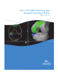
1
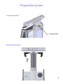
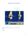
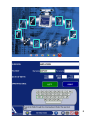
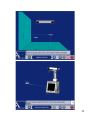
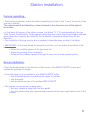
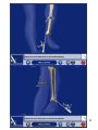
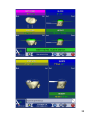
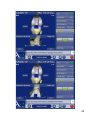
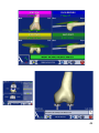
Navigated Surgical Technique SCORE® Revision Total Knee Prosthesis TO.G.GB.007/1.0 Preparation phase Locked position Locking handle Unlocked position 2 Preparation phase • Position the station in relation to the patient (Reminder: minimum distance 1,5 m). • Regulate the optical head in neutral position (at maximum height and without rotation). • Unlock the mobile column: lift the locking handle and let the column rise freely to high position. • Press the green stop/go button at the back of the station. Button in position « I » 3 Screen description 4 Description of permanent buttons 5 6 Preparation phase • Select the image of PTG SCORE® Revision surrounded by blue. • You arrive at the opening page. • To access the first screen, press the blue arrow. • Information Page: Patient information stage. • Use the keyboard to type the information on the tactile screen: • Surgeon’s name • Patient’s name • Patient’s date of birth (not obligatory) • Side to be operated (press the button corresponding to the operated side) • To go to the following stage validate by using the blue pedal or by pressing the blue arrow on the screen. • To return to the preceding stage, validate by using the yellow pedal or by pressing the yellow arrow on the screen. 7 Clip button Jig Limit between rigid part and support Patella Fixing pins Fixing Support Femur Jig Femur Fixing pins Jig Tibia Markers 8 Installation of jigs • Clip the spherical markers on the jigs: • 3 for the T (tibia) • 3 for the F (femur) • 4 for the P (probe/pointer) • 3 for the G (guide) • The fixing pins should be placed in internal antero on the femur and the tibia and should not get in the way of the screw-tap installation. They can either be installed firstly through the cut, or under the skin. • Install the first pin (go across the 1st cortical and fix it in the 2nd cortical without going across it). • Put the system of fixation of jigs on this pin, so as to obtain the right spacing to fix the second pin. • Clip the rigid part of the femur (be careful to respect the direction of the arrows) on the movable part of the fixation system. If it is necessary during the operation to remove the rigid structure, this will be placed in the same way. • Direct the jig towards the optical head and lock the fixation system. • Direct and fix the jig so that with the leg flexed or not, the jigs can always be seen by the optical head. •After opening and exposing the knee using the separators provided, it is important to do the exeresis of the osteophytes in order to find the right articular surfaces to palpate for the digitalization of articular surfaces (otherwise risk of over or under-estimating the size of the implant). 9 10 Station installation Camera regulating : • Position the localisator so that the letters indentifying the jigs F and T are in the center of the volume of visibility. This adjustment is facilitated by a laser situated in the direction arm of the optical localisator. • In the lower left corner of the station screen, the letters T F P G corresponding to the jigs Tibia, Femur, Probe/Pointer, Guide appear (when they are used in the current stage) coloured green when the receptors are visible by the localisator, coloured red when they are not detected. • The invisibility of the jigs may be due to parasite infrared sources (sunlight, hot lights). • IMPORTANT: At all times during the surgical procedure, you can adjust the position of the cameras: • Select the visibility square of the jigs lower left • Adjust the position of the localisator • Re-select the visibility square of the jigs to return to the initial operating time Screen calibration : • Point the probe/pointer in the direction of the center of the AMPLIVISION® screen and validate by pressing the trigger. • From this stage on it is possible to pilot AMPLIVISION® either : • with the probe/pointer by pressing the trigger to validate • with the pedal • with the tactile screen of the station AMPLIVISION® • The system records screen images when: • the user validate a stage with the blue pedal • the user presses the icon representing a camera at the lower right hand corner of the screen 11 12 Calibration probe/pointer and jigs Calibration of probe/pointer : This stage is divided into two parts: • To calibrate the point of the probe/pointer place the end in the calibration cone situated on jig T and validate by pressing the trigger. • Without lifting the point of the probe/pointer, repeat the same operation while slightly changing the direction of the probe/pointer and validate. Tibia confidence point : • Place the point of the probe/pointer in the calibration cone which can be found on the support of jig T and validate. • The definitive position of jig T on its fixation support can be validated by this manipulation. Throughout the procedure it is possible to check if this position has been modified. Femur confidence point : • Carry out the same manipulation with the support of jig F. At any time during the surgical procedure, you can put the point of the probe/pointer in the tibia and/or femur confidence point. In the lower left-hand corner of the screen, the message « Tibia OK » and/or « Femur OK » appears if the jig has not moved. If it is not the case, depending on the operative stage reached, either you continue the procedure in the normal way, or you return to this calibration stage. 13 14 Acquisition of the center of the ankle Medial malleolus: • Place the point of the probe/pointer on the most distal point of the medial malleolus. • Validate the position by pressing the trigger of the probe/pointer. Lateral malleolus: • Place the point of the probe/pointer on the most distal point of the lateral malleolus. • Validate the position by pressing the trigger of the probe/pointer. 15 16 Acquisition of the center of the hip Acquisition of the center of the hip : • With the leg extended, take hold of the patient’s heel. • Press the blue arrow (or the blue pedal) to begin the acquisition of points. • Carry out a circular movement with the leg, of a radius of 15 cm around the knee. • Once the acquisition is completed, the system calculates the center of the hip. If the result is satisfactory, the system proceeds automatically to the following stage. Otherwise the system requests that the acquisition be recommenced. During this stage, a beeping sound indicates the beginning of the acquisition, cursor simulating the acquisition appears at the bottom of the screen and a beeping sound indicates the end of the acquisition. 17 18 Tibial acquisitions Centre of the tibia: • Palpate the centre of the tibial plateau. • Validate the position by pressing the trigger. Medial articular surface: • The frontal plane of the tibia will be chosen by the surgeon and drawn by electric scalpel on the tibial plateau (in the middle of the articular surfaces). • Palpate a point in the middle of the medial articular surface (on the axis already traced). • Validate the position by pressing the trigger. Lateral articular surface: • Palpate a point in the middle of the lateral articular surface (on the axis already traced). • Validate the position by pressing the trigger. 19 20 Tibial acquisitions Acquisition of the tibial anatomic relief : • • • The objective of this stage is to acquire the bone surface of the tibia and to test the precision of this acquisition. Place the point of the probe/pointer on the bone surface, press and hold down the trigger and move the point over the articular surface to be acquired. It is preferable to carefully draw the contour of the tibial plateau (size of future implant) and to take points in the zone where the tibial cut will be carried out. • Attention: always leave the point of the probe/pointer in contact with the tibial surface. • When you press the trigger of the probe/pointer, the acquisitions begin, and removing pressure from the trigger puts an end to the current acquisition. • • A bip sound starts and ends the acquisition surface procedure. When the 3 « interest zones » indicated by red cubes (anterior, medial and lateral) turn green, this means that the minimum quantity of points for these zones has been obtained. Control green lines to the right of the screen are in the contact of the bone. During the acquisition of points, the articular surface is distorted in real time. • • Interest zones: • They are represented by fixed red lines and cubes at the beginning of the acquisition, then green and moving during the acquisition. • They are 3 of them: medial, anterior, lateral. • They represent the minimal zones of reference to determine the size and to position the embase. 21 22 Tibial acquisitions Verification of global acquisition: • Take the pressure off the trigger, and move the point over the articular surface. The system calculates the distance between the point of the probe/pointer and the 3D model. • Move the probe/pointer over the bone. The probe/pointer appears in green when the distance between the model and the reality is less than a millimetre, and in red when the distance is more than a millimetre. In the event of incorrect acquisition: • It is possible to cancel the latest 20 points acquired by pressing the yellow pedal. • A prolonged press (more than 2 seconds) cancels the totality of acquired points. • If the precision of the distorsion is satisfactory, validate so as to pass on to the next stage. 23 24 Femoral acquisitions Summit of the notch: • Palpate the summit of the notch. • Validate the position by using the trigger. Medial posterior condyle: • The axis of the posterior femoral condyles is defined by the acquisition of a point on the medial and lateral posterior condyle. • Palpate the most posterior point of the medial condyle. • Validate the position by using the trigger. 25 26 Femoral acquisitions Lateral posterior condyle : • Palpate the most posterior of the lateral condyle. • Validate the position by using the trigger. Anterior cortical: • Palpate a point on the anterior cortical. • Validate the position by using the trigger. 27 28 Femoral acquisitions Acquisition of the femoral anatomic relief : • The objective of this stage is to acquire the bone surface of the femur and to verify this acquisition • Place the point of the probe/pointer on the bone surface, press the trigger and hold it down while moving the point over the femoral surface • During the acquisition of points, the articular surface is distorted in real time. • It is preferable to carefully draw the contour of the femur. • At any time it is possible to release the trigger, position the point of the probe/pointer elsewhere, and continue the acquisition by pressing the trigger again. • Attention: Always leave the point of the probe/pointer in contact with the femoral surface. • The acquisitions are begun by pressing the trigger (or the blue pedal), releasing the trigger ends the acquisitions. • A bip sound starts and ends the acquisition surface procedure. • When the 7 « interest zones » indicated by red cubes (anterior, medial distal, lateral distal, medial posterior, lateral posterior, medial and lateral) turn green, this means that the minimum quantity of points for these zones has been obtained. Control green lines to the right of the screen are in the contact of the bone. • During the acquisition of points, the articular surface is distorted in real time. 29 30 Femoral acquisitions Precision verification: • Release the trigger, and move the point over the articular surface. The system calculates the distance between the point of the probe and the 3D model. • Move the probe/pointer over the bone. The probe/pointer appears in green when the distance between the model and the reality is less than a millimetre and in red when the distance is more than a millimetre. • It is possible to obliterate the last 20 points acquired by pressing the Yellow pedal. • Holding the trigger down (more than 2 seconds) obliterates all the acquired points. • If the precison of the distorsion is satisfactory, validate and go on to the next stage. If the acquisition has been incorrect: • It is possible to obliterate the last 20 points acquired by pressing the Yellow pedal. • Keeping the pedal down (more than 2 seconds) obliterates all the points acquired. • If the precision of the distorsion is satisfactory, validate and go on to the next stage. Acquisition of the pre-operative HKA angle: • Freely extend the leg. • Visualise the pre-operative HKA angle. • Validate and go on to the next stage. 31 32 Tibial planning Reference point : • Adjust the height of cut indicated in the corner down to the right of the screen, by using the + or – keys of the tactile screen. • Palpate the point which will serve as reference for the height of the cut. Between this point and the red line (the cut level) there will the thickness planned. For example in this case, the distance between the palpated point in the lateral side and the height of cut si 10 mm. • For chose the reference point you can help you with the topography on the tibia. The red 0 point is the higher point and the blue zone is the lowest. • The distance between the tibial cut (red line) and the lowest point of the tibial plate is indicated on the opposite side. For this example, the distance betwwen the tibial cut and the lowest point of the damaged side (medial side) is 8 mm. • Like that, the height of programmed cut will always be in comparison with the palpated point and the thickness of cut on the opposite side will be indicated for information. 33 34 Tibial planning Tibial planning : • A position and a size of the tibial embase in relation to the cut are proposed. • The calculated size of the femur is given by way of information. • The size and position of the implant can be adjusted by using the tactile screen keys. To modify a parameter select the position (it appears in green), then use the keys + or – to modify the values. • Press the « O key » to return to the schedule proposed by default. • Validate the schedule. 35 36 Tibial cut Calibration of tibial viewfinder : • Install the screw-tap. • Fix the jig G on the tibial viewfinder. • Install the viewfinder on the screw-tap. • Place the point of the probe/pointer in each of the 3 cones situated on the tibial viewfinder and validate each position with the trigger. A green cone guaranties the accurate acquisition. • The order in which this operation is carried out is not important. 37 38 Tibial guiding Navigation of the tibial cut : • The screen represents the different planes to be navigated, the viewfinder part to be used is identified by a colour code. • The scheduled value appears in green on the screen. • The navigated value appears in white if the viewfinder is not aligned correctly. It appears in green when the scheduled target is reached (with a precision of 1° or 1 mm). • When the viewfinder is in the right position, the value and the pal of cut appear in green. • Place the pins when all the navigated values correspond to the scheduled values. • Validate the position (blue pedal, probe/pointer, or directly on the screen). • Remove the screw-tap and the viewfinder, place the tibial cut guide on the pins. • Make the tibial cut. Acquisition of the plan of the cut: • • On a monoblock tibial palette, install the jig « G ». Position the monoblock tibial palette on the tibial cut already made and validate. 39 half wedge of 2, 4 or 6 mm mobile disc Adjustable spacer Adjustable spacer Complete wedge of 2 or 4 mm 40 HKA angle simulator and Ligamentary balancing Extended: • In extension, the adjustable spacer fills the space between the tibial cut and the non prepared femur. The adjustable spacer is provided with 2 mobile discs, adjustable by micrometric screw, which can fill the space on the side desired (after addition if necessary of a mobile half wedge of 2, 4 or 6 mm), until the desired HKA angle appears on the screen. If necessary, complete wedges of 2 or 4 mm can be added under the spacer (tibial cut side). Once the HKA angle has been adjusted, the surgeon can test, visualise and adjust the ligamentary balance by a ligamentary release and/or by modifying the position of the virtual femoral implant by using the navigator’s tactile screen. NB: The areas shown on the screen are those between the tibial cut already made and the virtual femoral prosthesis whose position is known to the computer. • • Flexed: • When the balance in extension is completed, flex the knee at 90°. Using the spacer adjusted for saturation equivalent to the height of the insert installed in the preceding step (= value read on the screen between the tibial cut and the virtual femoral implant, in extension), check the flexed areas as well as the ligamentary balance. The surgeon can simulate the external rotation of the virtual femoral implant to improve the balance of the areas by using the navigator’s tactile screen. Again, the areas appearing on the screen are those between the tibial cut already made and the virtual femoral prosthesis whose position is known to the computer. • Choice of a femoral distal cut of more than 8 mm : • • • A black line represents the contact zone between the internal distal surface of the femoral component and the distal cut. The thickness of the cut on the two condyles is visible. Increase the thickness of the femoral distal cut, using the tactile screen (from 2mm to 2mm) in case of: – distal cut inexistant or insufficient, of one of the two condyles (genu valgum) – large pre-operative flexum – need to go back to the interline 41 42 Medio-lateral positioning: • • • • • To place the virtual femoral component under the patella part, the navigation system can help you. Select the medio lateral key. The virtual femoral implant appeared at the bottom of the screen. To place the virtual femoral implant in medio lateral side according to the anatomic trochlea in white. If on the distal part there is a prothetic « surépaisseur » the value is indicated. These parameteres need to be regulate at 30°, 60° and 90° of flexion. Touch on the picture to change and seemed all views. 43 44 Femoral guiding Calibration of femoral viewfinder : • Install the screw-tap. • Attach the jig G to the femoral viewfinder • Install the viewfinder on the screw-tap. • Place the point of the probe/pointer in each of the 3 cones situated on the femoral viewfinder and validate each position with the blue pedal. A green cone guaranties the accurate position. • The order in which this operation is carried out is not important. 45 46 Femoral guiding Navigation of the femoral cut: • The screen represents the different planes to be navigated, and the part of the viewfinder to be used can be identified by a colour code. • The scheduled value appears in green on the screen. • The navigated value appears in white when the viewfinder is not correctly aligned. It appears in green when the scheduled objective is achieved (with a precision of 2° or 2 mm). • When the viewfinder is correctly aligned, the value and the cutting plane appear in green. • Install the pins when all the navigated correspond to the scheduled values. • Validate the position by pressing on the blue pedal. • Remove the viewfinder and the screw-tap. • Place the femoral cut guide of the appropriate size on the 2 pins. • Attach it using nails and anterior stabiliser. • Make the cuts. Navigation of the pre-cut, when the femoral distal cut is greater than 10 mm: After installing the pins, use the distal femoral reamer as indicated on the screen to make the scheduled pre-cut. • Place the reamer on the pin in contact with the condyle. • Adjust the stop to the value of the cut (at 4 mm if the pre-cut is 4 mm) using graduations (2mm by 2mm). • Perform the distal pre-cut. • Remove the viewfinder and the screw-tap. • Attach it using head nails stabiliser. • Perform the cuts. 47 48 Trochlear groove preparation Centring du guide de préparation d’échancrure: • Install the trochlear groove preparation guide. • Place the point of the probe/pointer on the anterior cone of the guide. The medio-lateral distance could be appreciated between the planned position and the real position of the trial condyle. • When the desired position is obtained, fixe the guide with 2 headed pins and prepare the trochlear groove. 49 50 Trial implants Acquisition of the final position: • Place the point of the probe/pointer in each of the 3 cones and validate each position by pressing with the trigger. • Validate each position. 51 52 Trial implants Finale position of the trial femoral condyle : • The trial implant in grey is superposed in the position of the scheduled implant in green. • The size and final position of the implant appear in white and the scheduling in green. Final position of the trial tibial embase : • Install the handle with the jig G on the trial tibial embassy (of the estimated size). • Place the trial embassy on the cut and visualise its position in medio lateral and antero posterior position in relation to that scheduled. (In white the navigated values, in green the scheduled values). • Fix the position of the embassy with 2 headed pins. • Validate the position of the embassy EITHER by validating with the jig G mounted on the handle, OR by acquiring the 3 calibration cones with the probe/pointer. 53 54 Trial implants and data recording Extension test : • Place a trial insert. • Place the leg in extension. • Visualise the HKA angle and the spaces (medial and lateral) with the trial components in place. • Valide the position. 55 56 Trial implants Flexion test : • Place the leg in flexion. • Visualise the spaces in flexion with the trial components in place. • Validate in the desired position by pressing the blue pedal to record the desired position in the operating report. • Other positions with different degrees of flexions can be recorded using the blue arrow. 57 Recording the surgical report Record the surgical report: • Press the red button to leave the application (lower right of screen). • Validate your intention to leave the application. • Validate your intention to save the surgical report. • Save the surgical report by inserting the USB key in the connection situated under the screen (see station description) and confirm save. • The surgical report is a file called « report.html » which follows the chronology of the procedure and includes these pages: • patient information and name of the surgeon • the result of bone deformities • programming pages of bone cuts • programming pages of position and size of implants • page of post operative validation • Remark: if you do not wish to save the surgical report, press « cancel » when the AMPLIVISION® system offers to save the surgical report. 58 Storing the station • • • • • • • • • • • • • When you leave the program, the first page appears. Press the « leave program » button. Validate closing the system. Wait for the message giving permission to close the station. Press the green sop/go button situated at the back of the station. Button in position « 0 ». Unplug the power cord and wind it around its rack situated behind the station. Disconnect the pedal. Adjust the optical head in neutral position (maximum height without rotation). Clean the station and the pedal (see user’s manual situated in the carrying case). Lock the movable column: lower the locking handle and pull it vigorously downwards to bring the column down completely. Replace the station in the carrying case. Place the pedal and the protective covers in the carrying case. Lock the 4 locking points of the carrying case. 59 SCORE® Revision Total knee prosthesis Navigated Instrumentation 60 Complementary information • Complementary to navigated/mecanical PTG SCORE® Revision , it is indispensable to have : - AMPLIVISION® navigation station - Amplitude SCORE® Revision integrated software - Sterile single use markers (box of 14) - AMPLIVISION® navigated version instrumentation Sterile Markers Single use sterile markers Non-resterilisable Box of 14 markers Setting the markers on the jigs 61 Complementary Fixation system F and T Tibial Reference Femur Reference Fixation pin Marker Probe/pointer Tibial Reference 62 Complementary 63 Complementary 64 Complementary 65 Complementary 66 Navigated instruments Prober/pointer: • This intrument is used to define precise points or surfaces on the patient’s anatomy. It is also used to give commands to certain active elements on the screen. The probe/pointer should be equipped with four markers, one of which is set up on the movable trigger. Fixed jig Movable marker on the trigger The universal handle and the monoblock tibial palette for tibial cutting acquisition: • The navigated universal handle and the monoblock tibial palette have two fixation points for the guiding jig (one on each side). Monoblock tibial palette Navigated universal handle 67 SCORE® Revision Saw blades SYNTHES AO SODEM étroite STRYKER 2000 étroite 3M Maxi Driver étroite STRYKER B étroite AESCULAP étroite ZIMMER HALL étroite 68