1
General power supply description
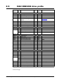
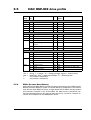
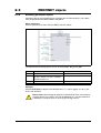
The Ethernet modules can be used in the allmost all the MAC motors but please be
aware that to use the MAC50 to 141 they will need the special option : “A009” for example “MAC140-A1-AAAA-A009”
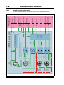
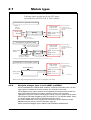
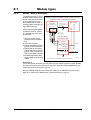
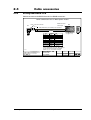
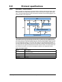
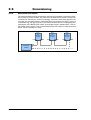
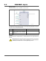
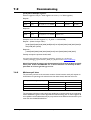
. The diagram below shows how to connect power to a MAC400 motor mounted with
a MAC00-Ex4/-Ex41 module. Please notice that the voltage connected to P+ and/or CVI
must stay in the range +12-26VDC. When using a MAC50 to 141 up to 48VDC is allowed.
See also the general power supply description in the MAC motor main manual LB0047.
For further information concerning physical connections, see the Expansion module
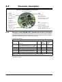
MAC00-Ex4 (basis version) connector description, page 20.
Power supply connections to a MAC400
mounted with a MAC00-Ex4 module.
Power supply
+12-26VDC
Make sure that all
involved units are
connected to the same
potential
(control voltage)
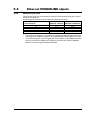
2.2.3
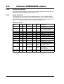
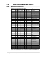
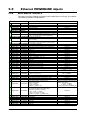
Module types
GND
2.1
MAC400 Motor
with MAC00-Ex4
Power
Supply
Control Volt.
P+
PCVI
Main supply
It is recommended
that a separate supply
line is used for each motor.
Max. 26VDC !
Mains 115 or 230VAC
MAC400 Motor
with MAC00-Ex4
Power
Supply
Control Volt.
P+
PCVI
Main supply
Max. 26VDC !
Mains 115 or 230VAC
TT3011GB
JVL Industri Elektronik A/S - User Manual - Ethernet expansion modules for MAC motors
17