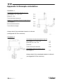
1
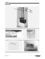
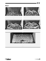
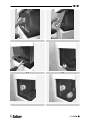
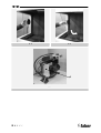
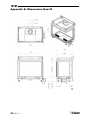
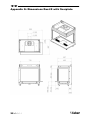
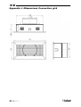
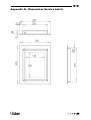
DUET 40010731-0842 UK Installation Guide IRL UK IRL General A 30cm 1.1 1<<<< 1.2 1.3 1.4 1.5 UK IRL Duet 2.1 2.2 2.3 2.4 2.5 >>>>2 UK IRL 3.1 3<<<< 3.2 3.3 3.4 3.5 UK 3.6 3.7 3.8 3.9 4.0 4.1 IRL >>>>4 UK IRL 4.2 4.3 A 5.1 5<<<< UK IRL Content 1 Introduction ......................................................................................... 7 2 Safety and general information .................................................................. 8 3 Installation requirements ......................................................................... 9 4 3.1 Chimney breast ............................................................................... 9 3.2 Surround with cover plate .................................................................. 9 3.3 Placing the service hatch ................................................................... 9 3.4 Flue requirements............................................................................ 9 3.5 Flue restrictor ............................................................................... 10 3.6 Terminal position ........................................................................... 10 3.7 Using an existing chimney. ................................................................ 11 Instruction for Installation ....................................................................... 12 4.1 Gas Connection .............................................................................. 12 4.2 Electrical connection ....................................................................... 12 4.3 Preparation of the appliance.............................................................. 12 4.4 Removing the glass.......................................................................... 12 4.5 Placing the appliance....................................................................... 13 4.6 Constructing the chimney breast ......................................................... 13 4.7 Placing the side glas. ....................................................................... 14 4.8 Placing the bottom plate .................................................................. 14 4.9 Placing the pebbles ........................................................................ 14 4.10 Placing the front glass...................................................................... 14 5 Commissioning (functional checks) ............................................................. 15 6 Handing over (final check and customer briefing) ........................................... 17 7 Servicing ............................................................................................ 17 Appendix A: Example calculation..................................................................... 19 Appendix B: Flue restrictor............................................................................ 20 Appendix C: Installation of the flue.................................................................. 21 Appendix D: Technical specifications Flatburner .................................................. 22 Appendix E: Dimensions Duet R....................................................................... 23 Appendix F: Dimension Duet L ........................................................................ 24 Appendix G: Dimensions Duet R with floorplate ................................................... 25 Appendix H: Dimensions Duet L with floorplate ................................................... 26 Appendix J :Dimensions Convection grid ............................................................ 27 Appendix K : Dimensions Service hatch ............................................................. 28 >>>>6 UK IRL 1 Introduction Note: these instructions should be read carefully and retained for future reference. Please leave these instructions with the user. The Duet is available in a left and a right version. According to commonly accepted definitions in the Fire place business (in front view) the left version has a blinded side at the right and a right version has a blinded side at the left. See also appendix E, F, G and H. Before opening the crate always check if the desired version has been delivered! Special features: • Room sealed appliance, inlet and outlet are led to the outside using a natural draught concentric pipe system (100 mm/150 mm) (no power fan required) • Air supply and flue-gases go to outside atmosphere through wall or roof. A horizontal extension is possible (see appendix A and B). • Remote Control is standard. • This appliance comes standard with two convection grills and one service hatch • The appliance can be placed in two ways: standing on the floor and hanging on the wall • Meets the requirements of the European Gas Appliance Directive (GAD) and carries the CE mark. 7<<<< UK IRL 2 Safety and general information Before installation, ensure that the local distribution conditions (identification of the type of gas and pressure) and the adjustment of the appliance are compatible. This gas appliance is factory set and can not be adjusted. This appliance does not contain any component manufactured from asbestos or any asbestos related products. Ventilation This appliance is room-sealed and doesn't require purpose provided ventilation. Never use the appliance if it has a broken glass. General safety It is the law in the UK that all gas appliances, are installed by a competent person in accordance with the Gas Safety (Installation and Use) Regulations (as amended), the relevant British Standards for Installation work, Building Regulations, Codes of Practice and the manufacturers instructions. Always use an additional guard if there are elderly, infirm or children in the same room of the appliance. The installation should also be carried out in accordance with the following where relevant: • BS5871 Part1 • BS5440 Parts 1 & 2 • BS1251 • Building Regulations Document J (as applicable) • Building Regulations and Standards issued as relevant by the Department of the Environment or the Scottish Development Department • In the Republic of Ireland installation should be carried out in accordance with IS813, ICP3, IS327, Building Regulations, Codes of Practice, the manufacturers instructions and all other regulations in force Failure to comply with the above could leave the installer liable to prosecution and invalidate the appliance warranty. >>>>8 UK IRL 3 Installation requirements Note: Since the appliance is a source of heat, circulation of air occurs. Therefore it is of importance that you do not use the appliance shortly after a renovation of the home. Due to the natural circulation of air, moist and volatile components from paint, building materials, carpet etc. will be attracted to the lit appliance. These components can settle onto cold surfaces in the form of soot. As on all heat producing appliances, soft furnishings such as blown vinyl wallpaper placed too near the appliance may become scorched or discoloured. This should be born in mind when installing the appliance. 3.1 Chimney breast The appliance must be built into a chimney breast. This can be an existing or a new chimney breast. In either case, take the following points into account: • The chimney breast must be constructed of an inflammable material. • Always install the hearth first before constructing the chimney breast. • Always ventilate the space above the hearth by means of the grates supplied or a comparable alternative with a minimum air supply of 20000 mm². • Use special stucco (min. 100°C resistant) or glass fibre wallpaper to prevent discoloration or tears etc. Recommended drying time: 1 day per mm finishing coat applied. 3.2 Surround with cover plate • If the cover plate (which can be optionally ordered) is used, the chimney breast must be placed at the same height as the bottom of the recess. (see figure 1.2). 3.3 Placing the service hatch • The gas control valve is generally mounted onto the hearth with a brace. Unscrew it and mount the brace with the gas control valve onto an easily accessible spot behind the service hatch (max. 1m. from the centre of the hearth in connection with the length of the flexible gas pipe). 3.4 Flue requirements • The appliance is of the type C11/C31. The appliance will need to be supplied with the approved Faber flue pipes and terminal, it is not possible to supply your own. The minimum effective height of the flue system must be 1 meter. • Flue routing: • a horizontal extension with elbows is allowed for a maximum of 4 meters. • vertical max. 12 meters (without horizontal extensions only) 9<<<< UK IRL Determine with the help of appendix A, B and C if the desired routing is possible. To establish this you will need to calculate: The effective height (this is the real difference in height between the upper side of the appliance and the terminal) The total horizontal extension. This is the total horizontal flue length where: 1. each 90-degree bend, which is in the horizontal area, counts for 2 meter 2. each 45-degree bend, which is in the horizontal area, counts for 1 meter 3. elbows and bends at the transition from horizontal to vertically are not to be counted 4. the wall mounted terminal counts for 1 meter 3.5 Flue restrictor If applicable, in the table of appendix B is also stated the size of a flue restrictor. This restrictor needs to be fitted in the combustion chamber when placing the appliance. Normally the smallest flue restrictor is fitted at production. 3.6 Terminal position Verify if the required terminal position meets the local installation regulations regarding disturbance, good functioning and ventilation: • The terminal must be located so that the outlet is not obstructed. If the flue terminal is located within 2 meters of a footway path or where people could come into contact with it, then a suitable terminal guard must be fitted • Terminals located close to shared walkways, footpaths etc. could be subject to legal constraints and this should be pointed out to the customer before installation. If in any doubt about flue location advice should be sought from local building control, or if appliance-related, from the manufacturer including wherever possible a dimensioned sketch • Avoid locating the terminal in close proximity to plastic materials such as gutters or other combustibles. If this is unavoidable then a suitable deflector should be made. • Some important requirements for a good functioning are • The wall-mounted terminal has to be at least 0,5 m off: o Corners of the building o Below eaves o Balcony's etc. unless the duct is dragged to the front side of the overhanging part o The roof mounted terminal has to be at a distance of at least 0.5 meters of the sides of the roof, excluded the ridge > > > > 10 UK IRL 3.7 Using an existing chimney. You can connect the appliance onto an existing chimney. The existing chimney then functions as air supply, where a flexible stainless steel liner (to BS715) of 100 mm performs the flue function. Requirements: • Any existing chimney used as an air supply must only service this appliance. • A chimney that has previously been used for solid fuel must be swept before use. • The existing chimney needs to be airtight. • The existing chimney needs to have an opening of min. 150 x 150 mm. • The chimney needs to be intact and well looked after. • Use the adjustable roof-mounted-terminal especially made for this, and the chimney connection set. For more information see the manual `Chimney Connection Set` delivered with the set. 11 < < < < UK IRL 4 Instruction for Installation 4.1 Gas Connection • Installation pipes should be in accordance with BS 6891. Pipe work from the meter to the appliance must be of adequate size. • The complete installation including the meter must be tested for soundness and purged as described in the above code. • A means of isolation must be provide in the supply to facilitate servicing. The connection should be made in 8 mm copper or similar semi flexible tube. (max 1 meter). Ensure that the gas pipe does not interfere with the removal or replacement of the burner tray or of the controls. The gas connection is nut and olive suitable for 8 mm pipe. 4.2 Electrical connection If the adapter is used a wall socket 230VAC – 50Hz must be mounted in the close neighbourhood of the hearth. 4.3 Preparation of the appliance • Remove the appliance from the crate and the pallet. Make sure you don’t damage the flexible gas pipes. • Remove the glass and take out the separately wrapped parts of the appliance! (see par.4.3.1.) 4.4 Removing the glass • Clear out a safe place to put down the glass. • Remove the bottom sealing ledge. (see fig. 3.2 and 3.3) • Place the suction cups on the front glass. (see fig. 3.4) • Remove the top and bottom sealing cord on the front. (see fig. 3.5) • Gently push the glass upwards so that the bottom is free of the groove and now gradually tilt the glass forwards and downwards. (see fig. 3.6 and 3.7) • Remove the bottom grate. (see fig. 3.8) • Remove the sealing strip (depending on the version the strip is situated at the left or at the right; see fig. 3.9) • Place a suction cup on the side glass. (see fig. 4.0 ) • Remove the sealing cord. strip (depending on the version the strip is situated at the left or at the right; see fig. 4.1) > > > > 12 UK IRL • Push the glass upwards so that the bottom is free of the groove and now gradually tilt the glass inwards and downwards. (see fig. 4.2 and 4.3) 4.5 Placing the appliance • Follow the instructions as indicated in the installation instructions before you continue installing. • First make sure the appliance is installed and connected, before placing the chimney breast. • Prepare for the connection of the gas supply. 4.5.1 Standing on the floor • If the hearth is placed standing upright, this should be adjusted to the correct height and level: (see fig. 1.3) o Rough height adjustment: using the retractable leg, or when the hearth needs to be placed at a higher level: using the long leg additionally supplied. o Accurate: using the unscrew able legs on which the hearth rests. • Place the flue tube system (see appendix C). 4.5.2 Mounted on the wall • Mount the wall brace supplied level and in the desired position on to the wall by means of the wedge bolts supplied. (see fig. 1.4) • Suspend the hearth from the wall brace and adjust it to a level height by means of the adjustable strut situated underneath the hearth. • 4.6 Place the flue tube system (see appendix C). Constructing the chimney breast Always place the ventilation grates supplied or a comparable alternative in the chimney breast so that the heat is transported to the (living)space by natural draught. Place the ventilation grates approx. 30 cm below the ceiling. Directly above the grates, place an additional protection panel of inflammable material. (see fig. 1.1). The chimney breast must be constructed against the built-in rack. Make sure the chimney breast is not supported by the rack. If the chimney breast is made of stone, a lintel must be used to support the masonry. This can be ordered from your supplier. 4.6.1 Construction with use of floor plate • With the use of a floor plate which can be optionally supplied the height of the lower part of the chimney breast must be level with the height of the 13 < < < < UK IRL bottom of the recess. (see fig. 1.2). This because of the extra height of the cover plate. • The chimney breast can be constructed in the same way as described in par. 4.5. • The cover plate can be placed onto the built-in rack now. 4.7 Placing the side glas. The placement of the side glas takes place in reverse order as is indicated in par. 4.3.1. 4.8 Placing the bottom plate • Replace the bottom plate grate in the inner frame. • Fill the bottom plate with part of the chips supplied. Divide the chips evenly and avoid thick layers on the burner bed. (see fig. 2.1). • Place the logs in gradual steps as indicated in fig. 2.2, 2.3 en 2.4 and make sure that the chips are not covered completely by the logs. • Spread the last chips around and between the logs. • Check if the pilot light is not covered by chips or a log. • Place the front glass now. 4.9 Placing the pebbles • Replace the bottom grate in the inner frame. • Fill the grate with the pebbles supplied (see fig. 2.5). Divide the pebbles evenly and avoid thick layers on the burner bed. • Check if the pilot light is not covered by pebbles. • Place the front glass now. 4.10 Placing the front glass. Remove any finger marks that might have been put on the glass during the placement. These finger marks will burn into the glass once the hearth has been lit and are then impossible to remove! The placement of the front glass takes place in reverse order as is indicated in par. 4.3.1. > > > > 14 UK IRL 5 Commissioning (functional checks) For a pre-delivery check, carry out the following tests: 5.1.1 Check function and ignition pilot light and main burner. • Check whether the pilot light is not covered by chips, a log or pebbles. • Ignite the hearth as is described in the user’s manual. • Check whether the pilot light is situated properly above the main burner. • Check the gas pipes at all connections and gas nipples for gas leakage with a gas leak detector spray or a gas leak detector. • Check the ignition of the main burner on full output and low output. (ignition should be flawless and easy). 5.1.2 Check the flue pipe system • Let the hearth burn on full output. • Check the flame image. There should be no flames against the glass and an even distribution of the flames. If this is not correct, check the positioning of the wood in the grate and the quantity of chips on the burner. • After 20 minutes, check if the flames burn a clear yellow. In case of blue flames, turn the fire off. Check: • The connections of the pipes (no leakage). • The mounting of the outlet. In case of wall transit, the proper side up. In case of roof transit, the proper place (see also chapter 3). • Whether the maximum length of the flue pipe has not been exceeded. • Whether the correct baffle has been mounted. 15 < < < < UK IRL 5.1.3 Checking the initial pressure and the burner pressure The appliance has been adjusted to the correct burner pressure. Adjustment of the burner pressure is not necessary. Because the initial pressure after DIY installation is not always correct, we recommend that the initial pressure is checked after installation and repairs. Measuring initial pressure: • Turn off the appliance spigot. • Turn open measuring point B (see fig. 1.5) by some rotations and connect a measuring tube to the gas control valve. • Check whether the pressure measured agrees with the pressure mentioned on the type plate. • Measure this when the hearth is on full output and when it is only on the pilot light. • If the pressure is too low, check if the diameter of the pipes is sufficiently large. • If the pressure is too high (more than 5 mbar or higher) you are not allowed to connect the appliance and you must get in touch with your energy supplier. Measuring burner pressure: Only perform this check if the initial pressure is correct. Measuring the burner pressure can be done on the gas control valve. • Turn open measuring point A (see fig. 1.5) by some rotations and connect a measuring tube to the gas control valve. • The pressure should agree to the value mentioned on the type plate. In case of any deviations, get in touch with your supplier. Note: after checking the initial or burner pressure always close the pressure measuring points and check whether they are fully closed! > > > > 16 UK IRL 6 Handing over (final check and customer briefing) Instruct the customer on the full operation of the appliance and the remote control, including replacement of batteries Advise the customer how to clean the appliance including the glass Hand over these instructions including the user guide to the consumer Recommend that the appliance should be serviced by a competent person at least once a year 7 Servicing To ensure safe, efficient operation of the appliance, it is necessary to carry out routine servicing at regular intervals. It is recommended, that the fire is inspected/serviced by a competent person at least once a year. Important: Turn off the gas supply before commencing any servicing. Always test for gas soundness after refitting the appliance! Routine anual servicing Clean (if necessary): a. the pilot system b. the burner c. the combustion chamber d. the glass Check the log layout and replace the embers (if applicable) Do the operating test as described in chapter 6 Check the flue system and terminal for damage and soundness (visual inspection) Cleaning the glass Depending on the intensity of use, you can get material deposits on the glass. Remove the glass (see chapter 4.6). Remove the deposit with a special ceramic glass cleaner (ceramic hob cleaner) as follows: Remove the front and the back. Clean the glass. Handle the glass with clean hands, wear gloves if possible. To fit the glass, proceed in reverse order. Make sure that the log set has been installed correctly before fixing the glass. 17 < < < < UK IRL Attention: Before placing the glass: check the glass sealing rope is in good condition and makes an effective seal. Be sure that there are no fingerprints on the glass. It is not possible to remove those prints after you burn the appliance for a while (they are burnt in). Place the glass in front of the appliance and fix the glass frame or use the glass clamps. Cleaning the combustion chamber and burner If the burner is visibly damaged, this can affect the distribution of the flame, if so then replace the burner: • Remove the front, glass, and log holder (if applicable) • Break the gas supply at the control valve. • Unscrew the burner assembly and take them out of the combustion • chamber. • Replace the burner assembly after cleaning > > > > 18 UK IRL Appendix A: Example calculation Calculation 1: Calculating horizontal extension fig. 2a: Flue length C + E = 1m + 1m 2m Elbows D = 2m 2m Total horizontal extension 4m Measure or calculate effective height (Hvert) Flue length A 1m Roof mounted terminal 1m Total effective height 2m Always check if the calculated situation is allowed (see appendix B: Flue restrictor) Calculation 2: Calculation horizontal extension fig. 2b: Flue length J + L = 0,5 + 0,5 1m Elbows K + M = 2m + 2m 4m Terminal 1m Total horizontal extension 6m Calculation effective height (Hvert) Flue length H 1m Always check if the calculated situation is allowed (see appendix B: Flue restrictor) 19 < < < < UK IRL Appendix B: Flue restrictor Determine the right flue restrictor: • Calculate the total horizontal- and vertical length of the flue, according to the calculations in Appendix A • Determine according to the table the right flue restrictor size • When meeting an X, and when the values are outside the table, the combination is not allowed Normally the 30 mm flue restrictor is pre-installed Horizontal length (m) Duet Real vertical Height (m) • 0 1 2 3 4 5 6 0 x x x x x x x 0.5 x x x x x x x 1 0 0 0 x x x x 1.5 0 0 0 0 0 x x 2 30 0 0 0 0 0 0 3 30 30 0 0 0 0 0 4 40 30 30 0 0 0 0 5 40 40 30 30 0 0 0 6 50 40 40 30 30 0 0 7 50 50 40 40 30 30 x 8 50 50 50 40 40 x x 9 65 50 50 50 x x x 10 65 65 50 x x x x 11 65 65 x x x x x 12 65 x x x x x x > > > > 20 UK IRL Appendix C: Installation of the flue Connection with use of concentric duct material Make a hole of ø 153 mm for the wall or roof mounted terminal. The horizontal pipes need to rise away from the appliance at a rate of 3 degrees per metre Build the system starting from the appliance on. Make sure you place the pipes in the right direction, the narrow end towards the appliance Make sure the pipes are fixed sufficiently, a wall clamp every 2m, so the weight of the pipes is not resting onto the appliance. The outside of the pipe can become hot (140 degrees). Stay 50 mm away from wall surface or sealing. Make sure to provide sufficiently heat resistant isolation when going through the wall or roof. Because of expansion or cooling down the concentric pipes can turn loose. It is recommended to fix the spring clip with a self tapping screw at inaccessible places. To get the exact measure flue length you can use cut down concentric pipe, wall mounted terminal or roof mounted terminal. To obtain a smoke sealed connection, the inner pipe must be 20 mm longer then the outside pipe. 21 < < < < UK IRL Appendix D: Technical specifications Flatburner Country Flatburner Flatburner UK / IRL UK / IRL Cat II 2E+3+ II 2H3+ Appliancetype C11 of C31 C11 of C31 Reference gas G20 G31 9.7 8.8 2 2 Input (nett) kW Efficiency class Inlet pressure mbar 20 37 Gas rate* l/h 1016 347 Gas rate* gram/h - 650 Working pressure (high) mbar 12.0 31.5 Injector size mm ST.800 ST.280 Reduced input restraint mm 2.10 1.30 Pilot assembly SIT 160 SIT 160 Code Nr.36 Nr.23 100-150 Flue system Flue size mm 100-150 Std. Flue restrictor mm 30 30 Gas control GV 60 C4E3M6M C5D3M6M Nut/olive 8 mm 8 mm Gas connection * at 15ºC and 1013 mbar > > > > 22 UK IRL Appendix E: Dimensions Duet R 23 < < < < UK IRL Appendix F: Dimension Duet L > > > > 24 UK IRL Appendix G: Dimensions Duet R with floorplate 25 < < < < UK IRL Appendix H: Dimensions Duet L with floorplate > > > > 26 UK IRL Appendix J :Dimensions Convection grid 27 < < < < UK IRL Appendix K : Dimensions Service hatch > > > > 28 UK IRL 29 < < < < UK IRL > > > > 30 www.faber.nl – [email protected] Saturnus 8 NL - 8448 CC Heerenveen Postbus 219 NL - 8440 AE Heerenveen T. +31(0)513 656500 F. +31(0)513 656501