1
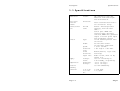
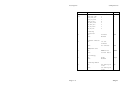
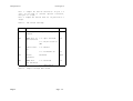
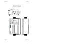
Remote Alarm TT-3042D Manual Thrane & Thrane Remote Alarm TT-3042D Manual Copyright Thrane & Thrane A/S ALL RIGHTS RESERVED Information in this document is subject to change without notice and does not represent a commitment on the part of Thrane & Thrane A/S. © 1998 Thrane & Thrane A/S. All right reserved. Printed in Denmark. Document Number TT98-110040-B. Release Date: 23 June 1998 Safety Summary The following general safety precautions must be observed during all phases of operation, service and repair of this equipment. Failure to comply with these precautions or with specific warnings elsewhere in this manual violates safety standards of design, manufacture and intended use of the equipment. Thrane & Thrane A/S assumes no liability for the customers failure to comply with these requirements. GROUND THE EQUIPMENT To minimise shock hazard, the equipment chassis and cabinet must be connected to an electrical ground with a low impedance wire by using the appropriate pin in the power supply connector. DO NOT OPERATE IN AN EXPLOSIVE ATMOSPHERE Do not operate the equipment in the presence of flammable gases or fumes. Operation of any electrical equipment in such an environment constitutes a definite safety hazard. KEEP AWAY FROM LIVE CIRCUITS Operating personnel must not remove equipment covers. Component replacement and internal adjustment must be made by qualified maintenance personnel. Do not replace components with the power cable connected. Under certain conditions, dangerous voltages may exist even with the power cable removed. To avoid injuries, always disconnect power and discharge circuits before touching them. DO NOT SERVICE OR ADJUST ALONE Do not attempt internal service or adjustments unless another person, capable of rendering first aid resuscitation, is present. DO NOT SUBSTITUTE PARTS OR MODIFY EQUIPMENT Because of the danger of introducing additional hazards, do not substitute parts or perform any unauthorized modification to the equipment. This page is intentionally left blank Table of Contents Table of Contents 1 Description..................................... 1-1 1.1 Specifications ........................... 1-2 1.2 Detailed description ..................... 1-4 1.3 Configuration ............................ 1-7 1.4 Installation ............................ 1-10 1.5 Connectors .............................. 1-12 1.5.1 X1 Power In ......................... 1-12 1.5.2 X2 I/O .............................. 1-12 2 Operation....................................... 2.1.1 Distress Transmission ................ 2.1.2 Status Indicators .................... 2.1.3 EGC Indicators ....................... 2.1.4 Mail Indicator ....................... 2.1.5 Call Group Reset ..................... 2.1.6 Audio Indicator ...................... 2.1.7 Dimmer Control ....................... 2.1.8 Paper Feed ........................... 2.1.9 Paper Load ........................... 2.1.10 Paper Saving ........................ 2.1.11 Dot Energy .......................... 2.1.12 Selftest Printout ................... 2.1.13 NMEA 0183 Sentence Input ............ 2.1.14 NMEA 0183 Sentence Output ........... 2.1.15 Serial Print input .................. 2.1.16 Remote Turn-On ...................... 2-1 2-1 2-2 2-2 2-3 2-3 2-3 2-4 2-4 2-4 2-5 2-5 2-5 2-6 2-6 2-7 2-8 3 Fault Diagnostics............................... 3-1 4 Outline......................................... 4-1 6Aug98 Page i Table of Contents This page is intentionally left blank Page ii 6Aug98 Specifications Description 1 Description This manual provides information for configuring, installing and operating the TT-3042D Remote Alarm. For general information regarding the Arcnet standard please refer to ATA Standards Committee’s ‘ANSI/ATA 878.1 Local Area Network: Token Bus (2.5 MBPS)’. For general information regarding NMEA 0183 standard, please refer to National Marine Electronics Association's 'NMEA 0183 Standard For Interfacing Marine Electronic Navigational Devices' Version 1.5 December 1987 or later. 6Aug98 Page 1-1 Description Specifications 1.1 Specifications Indication Visual: Call reset Distress transm. Arcnet/serial port OK button Printer Type: DB 15M conn: Width: Speed: Character size: Print direction: Paper roll: Supply Temperature Relative humidity Vibration Page 1-2 Voltage: Power: Operating: Storage: 2-15.8 Hz: 15.8-100 Hz: LED indicators with dim function. Text back-light with dim function. Patch covered button with 5 sec activation delay. Arcnet: Twisted pair/bus topology, max 100 meter cable. Serial port: NMEA 0183 receiver input optically isolated, NMEA 0183 generator output or Serial print input with Ready/Busy control 112 mm thermal printer with two motors. 40 char/line normal. 80 char/line compressed. 1 l/sec (normal). 9 dot high x 7 dot wide. Normal/Reverse, logic seek, word wrap. Width 112 mm, diam. 48 mm, length 25 m. 10.5-32 V floating DC. 2.5W standby, 7W printing. -10 to +50 Deg.C -20 to +70 Deg.C 95% non-condensing. 1.0 mm peak. 1.0 g peak. 6Aug98 Specifications Dimensions Description HxWxD: Weight: 117.5 mm x 213.9 mm x 57.5 mm. 1.3 kg. Table 1 TT-3042D specifications 6Aug98 Page 1-3 Description Detailed description 1.2 Detailed description The TT-3042D Remote Alarm for the Capsat TT-3020C and TT-3022D series of Inmarsat-C transceivers fulfil all GMDSS requirements for remote indication and printout of EGC SafetyNet messages, initiation of distress transmissions, and general system status display. The TT-3042D is connected to the transceiver through a single shielded twisted pair cable that may be extended up to 100 meters. The TT-3042D displays four types of EGC message priorities, a receive mail indication and a login status. A build-in printer enables hard copy printing of received EGC messages at the Remote Alarm location. The TT-3042D includes a distress button, allowing direct transmission of distress calls from the unit. A navigator with NMEA 0183 output can be connected directly to the TT-3042D for routing of position data back to the Capsat transceiver for automatic update of e.g. safety and distress information. The NMEA 0183 input port can be configured for serial input port for text to be printed, the protocol will then be two wire Ready/Busy. The NMEA 0183 input connector includes 3 additional EGC group outputs. These outputs allows additional alarm indicators to be connected in accordance with Your specific requirements. Page 1-4 6Aug98 Detailed description Description The TT-3042D is powered through its own 10.5-32 Vdc floating supply, conforming with the GMDSS requirements. Up to 7 Remote Alarm units with different Arcnet address setting can be placed on various locations onboard ship, all connected to one Capsat transceiver with the Arcnet. EGC SafetyNet messages are routed to all Remote Alarm printers connected. If no Remote Alarm is equipped with a printer or Remote Alarm printer fail, the EGC Safetynet message is routed to transceiver printer, computer printer or stored in disk. The build-in printer can be configured for 40 or 80 chars/line, automatic word wrapping is performed on long lines. When printing at 40 chars/line the TT-3042D perform papersaving compression on incoming data by stripping leading spaces and by allowing a maximum of two succeeding blank lines. The build-in printer can be configured for bottomto-top printing and automatic page breaking to allow printouts to be read directly from paperstrip at printout. The build-in printer is maintenance free, printing on 112 mm (4.4") width thermal paper rolls of length 24 meters. A build-in paper detector indicates when paper is low. The printer is temperature compensated to give equal printing quality over a wide temperature range. Paper loading is eased by extended feed length on paper empty condition. 6Aug98 Page 1-5 Description Detailed description Indicator and text background light selected by front panel operation. level is The TT-3042D is equipped with remote turn-on for power saving configurations. Remote turn-on is enabled by jumper setting. Page 1-6 6Aug98 Configuration Description 1.3 Configuration Before installation of the TT-3042D, configuration of Arcnet address should take place. It is important to observe that all devices connected to the same transceiver must have different address settings. If this is ignored, the Arcnet will not operate properly. The TT-3042D Remote Alarm is configured by setting an 8 position DIP switch located under the paper inlet. To set operating parameters remove paper and turn off power. Note: Operating parameters are only read at powerup or softreset so changes in operating parameters will not change operation until a power-cycling or softreset is performed. 6Aug98 Page 1-7 Description Configuration Position 1-3 4 5 Setting Fact. Address off,off,off: off,off,on: off,on,off: off,on,on: on,off,off: on,off,on: on,on,off: on,on,on: 1 2 3 4 5 6 7 8 1 Printing Direction on: off: Reverse Normal off Sounder Timeout on: off: 10 sec. Timeout no timeout 6 NMEA/Aux.Port on: off: NMEA 0183¹ Serial data² NMEA 7 Dot Energy on: off: High Normal High 40 Chars per line 80 Chars per line 80 8 Printing Width on: off: Page 1-8 off 6Aug98 Configuration Description note 1: Jumper W2 and W9 should be in pos 1-2 (low) in Rx mode to achieve optical isolation, else pos 2-3 (high). note 2: Jumper W2 and W9 must be in position 2-3 (high). Table 1: DIP switch settings. Jumpe r Function Fact . W1 Watchdog connect Only for debugging Shor t W2 NMEA 0183 in Optoisolated 1-2: Opto isolated 1-2 2-3: Rx/Tx return to GND W3 Remote TurnOn 1-2: Enable 2-3: Permanent On 2-3 W8 Arcnet balanced Balanced Open W9 NMEA 0183 out balanced 1-2: Balanced 1-2 2-3: Unbalanced Table 2: Jumper settings Main board. 6Aug98 Page 1-9 Description 1.4 Installation Installation To following brief outline may be used to get the TT-3042D up and running as a printer together with a Thrane & Thrane transceiver which supports Arcnet - hardware as well as software wise. 1. Set an unique Arcnet address as described in section 1.5.2. 2. Connect the 3042D to the transceiver by means of the accompanying interconnection cable (15 pole SubD connectors). 3. Connect the 3042D to a DC power source by means of the accompanying power cable. For security reasons take care to connect the ground/chassis wire properly to ground. When power is applied it should now be possible for the transceiver to print on the TT-3042D when needed or initiated by the user. In case the accompanying Arcnet interconnection cable is not suitable and another cabling has to be made please observe the guidelines given below regarding establishment of an Arcnet. Please note that the Arcnet system supported is a twisted pair in bus topology. Page 1-10 • The Arcnet bus should be wired as a bus meaning that there must be no branches or stubs. The Arcnet devices attached should be placed like pearls on a string. • The Arcnet bus will have two ends and both of these should be terminated with a 100 Ohm resistor (± 1%). The TT-3042D does NOT contain any termination-resistor. If needed the termination resistor could be placed in the 15 6Aug98 Installation Description pole SubD connector pair cable. This accompanying cable. connected to the twisted is the case for the • Always use shielded twisted pair cables shielded connectors (otherwise the specifications are not guarantied to fulfilled). • The length of the cable making up the Arcnet bus should be no longer than 100 meters. • Minimum spacing between devices connected to the Arcnet bus is 2 meter of cable. • No more than 8 Arcnet devices transceiver) must be connected to bus. and EMC be (including the Arcnet In case the NMEA input/output or serial input and/or the 3 status outputs have to be utilised please refer to section 1.5.2, 2.1.0 and 2.1.11 with respect to pin assignment, jumper setting and functionality. 6Aug98 Page 1-11 Description Connectors 1.5 Connectors 1.5.1 X1 Power In The pinout of the power supply input is as listed below. Pin 1 2 3 4 Function Battery Positive Battery Negative Ground Remote turn-on Sec. 2.1.1 3 1.5.2 X2 I/O The pinout of the I/O connector (15 pole SubD) is listed below. Pin 1 2 3 4 5 6 7 8 9 10 11 12 13 Page 1-12 Function Distress/Urgent, 100 Ohm, Open Collector Safety, 100 Ohm, Open Collector Routine, 100 Ohm, Open Collector Not Connected +5V DC, 39 ohm GND Arcnet A Arcnet B GND NMEA OUT A or Ready/busy (Controlled by W9) NMEA OUT B NMEA IN A or Serial input NMEA IN B or GND (Controlled by W2) 6Aug98 Connectors Description 14 15 6Aug98 Not Connected Not Connected Page 1-13 Connectors Operation 2 Operation The TT-3042D Remote Alarm for the Capsat series of Inmarsat-C transceivers operates as a message and status printer, it also displays the general system status. 2.1.1 Distress Transmission Distress transmission is activated by lifting the protective cover and pressing the Distress button for 5 seconds. When the Distress button is pressed the light in button turns on. When the Distress button has been pressed for 5 seconds, the sounder starts to beep to indicate that the distress request has been send to the Capsat transceiver. The Distress button can now be released and the sounder stops. The Distress button light starts flashing and continues to do so until a successful distress call has occurred. After that, the Distress button light turns on. If the Distress button light does not turn on and the sounder starts to beep when Distress button is pressed, the Remote Alarm is unable to issue the distress request. If the Power diode is flashing there are no Arcnet connection to Capsat transceiver. Please notice that it is not possible to cancel a distress transmission from the TT-3042D once a request has been send to transceiver. 6Aug98 Page 2-1 Operation Connectors The distress switch is patch covered to prevent unintentional use. 2.1.2 Status Indicators Power: The power diode is used as a power-on indicator, furthermore this diode indicates communication status with the transceiver. When the transceiver is turned off or the Arcnet connection is disconnected, the power diode is flashing to indicate the fault situation. Login: The Login diode is used to show the login status for the transceiver. When turned on the transceiver is logged in. Paper: The Paper diode is used to show the paper status for the printer. When turned on paper low is detected and printing is disabled. When paper is loaded and paper is detected the paper diode is flashing in 20 seconds or until OK is pressed before printing is resumed. Feeding distance is increased when paper empty is detected. 2.1.3 EGC Indicators When receiving an EGC message, the corresponding diode turns on and the sounder gives notice. When message is acknowledged and the OK button is pressed, the diode turns off at all Remote Alarms. Distress/Urgent: The Distress/Urgent diode is used as an indicator for the two highest levels of EGC, these are distress and urgent calls. The sounder turns on until the OK button is pressed. Page 2-2 6Aug98 Connectors Operation Safety: The Safety diode is used as an indicator for EGC safety information. Safety EGCs are usually SafetyNet navigational and weather information. Routine: The Routine diode is used as an indicator for EGC routine information. Routine EGCs are usually status and service messages for the Inmarsat-C earth stations. 2.1.4 Mail Indicator The Mail diode indicates that mail has been received by the transceiver. The Mail diode turns off when the OK button is pressed. 2.1.5 Call Group Reset The OK button is used as a single reset button for all call groups. If an EGC/Mail indicator is turned on, pressing OK button causes an receipt to be send back to the transceiver. 2.1.6 Audio Indicator The audio indicator gives a notice to attract attention when Remote Alarm status is changed. The sounder also gives a notice when communication status to Capsat transceiver is changed, printer error or printer paper empty is detected. It also turns on when an alarm request has been send to the transceiver. 6Aug98 Page 2-3 Operation Connectors The sounder timeout option, set by the DIP switch, must not be enabled when the TT-3042D is used as a remote alarm. The sounder timeout option must only be enabled when the remote alarm is used for printing only. When the timeout option is set the sounder will not be turned on for more than 10 seconds. 2.1.7 Dimmer Control Diode light level and text background light level is controlled by pressing the OK button and then pressing the FEED button a number of times. 2.1.8 Paper Feed Paper feed is activated by the FEED button. When paper Paper diode is turned on or flashing the feeding distance is increased. 2.1.9 Paper Load Use thermal paper rolls with width 112 mm (4.4") and max outer diameter 48 mm (approximate length 24 m). Use preferable high speed thermal paper for printer. To load paper do as follows. 1. Open roll kernel. holder and remove remaining roll 2. Press the Paper Feed switch to remove remaining paper. Page 2-4 6Aug98 Connectors Operation 3. Take off the sealing paper on new paper roll and pull out 50 to 60 mm. 4. Cut the edge of end of new roll to form an arrow. 5. Insert the edge of the paper in the paper feeding slot on printer and press Paper Feed switch. After a while the paper edge comes out. 6. Insert the paper roll in holder and close the roll holder. 2.1.10 Paper Saving For paper saving the TT-3042D cuts away succeeding blank lines. A maximum of two blank lines are allowed after each other. In 40 chars per line mode succeeding spaces are also cut away. 2.1.11 Dot Energy The printing energy used to write determines how black the printout is. each dot The dot energy is selected by DIP switch setting. When the dot energy is set to normal, printing head energy is lower and printer lifetime is prolonged. 2.1.12 Selftest Printout Selftest printout is initiated when OK and FEED is pressed at powerup. The selftest printout prints character set and DIP switch setting. Normal Remote Alarm operation is resumed after printout. 6Aug98 Page 2-5 Operation Connectors If OK is pressed for 15 seconds the Remote Alarm is softreset and selftest printout is initiated. 2.1.13 NMEA 0183 Sentence Input When configured for NMEA 0183 input/output the NMEA 0183 input can be connected to a navigator with a NMEA 0183 output. The input is optical isolated and only two wires are to be connected. Both inverted TTL (+5V/0V) and bipolar (-15-0V/1V15V) signal levels are accepted. The NMEA 0183 input is optical isolated when jumper W2 is in position 1-2 (low). The TT-3042D automatic detects if a NMEA 0183 navigator output has been connected. Standard NMEA 0183 messages are read, position and velocity data extracted and transferred to the transceiver. NMEA 0183 sentences read are: GGA, GLL, VTG, GXP, GDP, GOP, GLP, TGA, HDT and HSC. Please refer to navigator manual for further information. The NMEA 0183 communication parameters are: 4800 baud, 1 stopbit and no parity. Hint: To test the NMEA 0183 link the TT-3042D can be configured to serial data input on NMEA 0183 port, see section 1.5.2, NMEA 0183 sentences should then be printed out. 2.1.14 NMEA 0183 Sentence Output If the NMEA port is configured for NMEA 0183 input/output and NMEA 0183 data is received the Page 2-6 6Aug98 Connectors Operation position and velocity parameters are extracted and transmitted to the transceiver. If on the other hand no data is received on the NMEA 0183 line for a certain time the TT-3042D requests position and velocity data from the transceiver. If the transceiver is equipped with an internal GPS board and has updated position and velocity data these data is transferred to the TT3042D. The TT-3042D then transmits position and velocity formatted as standard NMEA 0183 sentences on the NMEA 0183 port Tx line. NMEA 0183 sentences output are: GLL, VTG and ZDA. When using the NMEA 0183 output jumper W9 should be placed in position 1-2 (low) to obtained a balanced signal. 2.1.15 Serial Print input When configured for serial characters input on NMEA 0183 port, jumper W2 and W9 must be in position 2-3 to obtain single-ended RS-232 voltage signals. The protocol is two wire Ready/Busy control. X2 pin 10 will go to a positive voltage level when buffer is full to indicate Busy. When printer is ready to accept data a negative voltage is output on X2 pin 10. Serial port is set-up to one start bit, eight databits, one stopbit, no parity and 4800 baud, the same as for NMEA data input. The port parameters are fixed. 6Aug98 Page 2-7 Operation Connectors 2.1.16 Remote Turn-On In power saving applications the TT-3042D can be turned on remotely. Jumper W3 must then be set in position 1-2 or the Remote Alarm will be turned on permanent. To turn on pin 4 on X1, the power connector, is connected to battery negative. To turn off pin 4 is disconnected form battery negative and left unconnected. Page 2-8 6Aug98 Connectors Operation This page is intentionally left blank 6Aug98 Page 2-9 Fault Diagnostics Fault Diagnostics 3 Fault Diagnostics If power diode does not turn on check voltage source and remote turn-on setting. fuse, If power diode is blinking then Arcnet connection to transceiver is failing. First check if transceiver is turned on, then check the Arcnet cabling, if no result then check Arcnet address settings for all units coupled to transceiver. 6Aug98 Page 3-1 Fault Diagnostics Fault Diagnostics This page is intentionally left blank Page 3-2 6Aug98 Outline Outline 4 Outline 6Aug98 Page 4-1