1
Руководство пользователя
GeoScan32
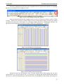
in the quantity equal to a quantity of profile readouts. The value of gain factors increases from left
to right up to the value "Factor” which is set in a window.
The trace of a georadar profile consists of a column of readouts. For signal alignment the
readout of each trace is multiplied by the relevant gain factor according to a serial trace number.
Usually the signal level on a trace drops with depth growth, so an increasing sequence of gain
factors is used for indemnification of this attenuation of the signal. The sequence of their products
will possess a smaller dynamic range than an original georadar signal and, consequently, it can be
preferable to visualization performed by program GeoScan32
The optimum form of an alignment line depends on characteristics of the scanned medium,
the aerial type and many other factors, therefore several methods of altering the form of a gain
curve are accessible in a window “Gain profile”:
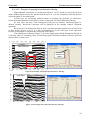
• Choice of the standard form of a curve: "Linear" or "Exponential". It is made by pressing of
the buttons with the same name. Pressing the button “Linear” draws a line from the left top
corner corresponding to the multiplier of alignment, which is equal to one, to the right lower
corner where the multiplier of alignment factor value will reach the maximum alignment value
specified in parameter “Gain factor”. Button "Exponential" similarly draws an exponential
curve, the deflection of which is regulated by parameter “alfa”.
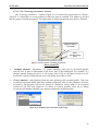
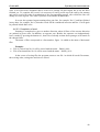
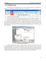
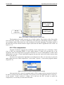
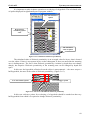
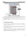
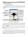
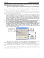
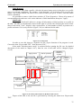
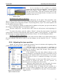
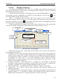
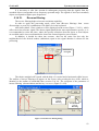
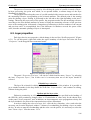
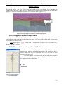
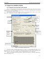
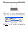
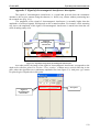
• Free form of a curve. If “Paint Mode” is activated (Figure 5.8.5), the user has a possibility to
draw a line in an arbitrary way, moving the mouse cursor with the left button kept hold.
• The gain profile can be changed in an arbitrary way, moving manually the elements of an
alignment curve with a mouse. Thus, together with a curve point corresponding to the position
of a mouse cursor the vicinity is pulled, its extent being set by the “Form Switch” in
percentage of the drawing window size (Figure 5.8.5). The form of a pulled vicinity is defined
by the “Form Switch” (Figure 5.8.5).
Modificated
vicinity of the
curve
Width
Control
Form Switch
Curve
Smoothing
Paint mode
Figure 5.8.5. Gain adjustment
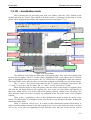
The button “Curve Smoothing” is used for mitigation of sharp changes (drops) of an
alignment curve (Figure 5.8.5). By consecutive pressing it the effect of smoothing enhances.
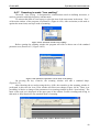
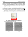
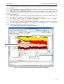
When there is a tick mark against “Inversion” (Figure 5.8.4), signal inversion occurs, i.e. all
amplitudes change their sign. Everything that was black in a radarogram becomes white and vice
versa.
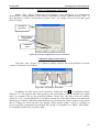
Besides simple change of a gain factor and the form of a gain curve, the window «Gain
profile» is accessible for application of such modes as Automatic Gain Control (AGC) and the
Mode of Indemnification of Wave Attenuation.
68