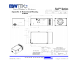
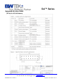
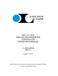
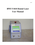
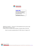
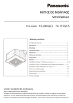
1
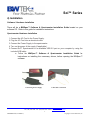
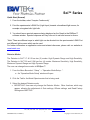
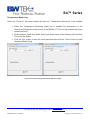
Sol™ Series TE Cooled Linear InGaAs Array Spectrometer User Manual 19 Shea Way, Newark, DE 19713, USA ·Web: www.bwtek.com Tel: (302) 368-7824 · Fax: (302) 368-7830 · Email: www.bwtek.com/contact 290020041-H (11/30/2011) Copyright © 2011 B&W Tek, Inc. Sol™ Series 1) Introduction The Sol™ Spectrometer Series delivers high performance and is equipped with a standard USB 2.0 interface for easy plug-and-play setup. The Sol™ spectrometer is ideal for NIR applications since it features two detectors modes; High Dynamic Range and High Sensitivity mode which can be changed by the end user. The Sol™2.6 and Sol™2.2A spectrometer features two additional detector modes, Maximum Dynamic Range and Maximum Sensitivity mode for a total of four selectable detector modes. The Sol™ spectrometer series exhibits low dark counts and precise detector cooling and temperature regulations which ensures precision data over long term operation. Custom configurations and custom application support is available. 2) Specifications See Product Datasheet for specifications. 3) Check Contents Before installation please check your system contents. They may include: Sol™ InGaAs Array Spectrometer unit AC Power Adapter USB cable AC Cord if applicable BWSpec™ Software CD Sol™ Spectrometer unit USB Cable AC Power Adapter AC Cord BWSpec™ Software CD 19 Shea Way, Newark, DE 19713, USA ·Web: www.bwtek.com Tel: (302) 368-7824 · Fax: (302) 368-7830 · Email: www.bwtek.com/contact 2 290020041-H (11/30/2011) Copyright © 2011 B&W Tek, Inc. Sol™ Series 4) Installation Software / Hardware Installation There will be a BWSpec™ Software & Spectrometer Installation Guide located on your software CD. Refer to this guide for installation instructions. Spectrometer Hardware Installation 1. Connect the AC Cord to the Power Supply. 2. Plug the AC Cord into an electrical outlet. 3. Connect the Power Supply to the spectrometer. 4. Turn on the power of the supply (if applicable). 5. Connect Sol™ Spectrometer to an available USB 2.0 port on your computer by using the included USB cable. a. Follow the BWSpec™ Software & Spectrometer Installation Guide for instructions on installing the necessary drivers, before opening the BWSpec™ software. Connecting Power Supply USB Cable Connection 19 Shea Way, Newark, DE 19713, USA ·Web: www.bwtek.com Tel: (302) 368-7824 · Fax: (302) 368-7830 · Email: www.bwtek.com/contact 3 290020041-H (11/30/2011) Copyright © 2011 B&W Tek, Inc. Sol™ Series 5) External Trigger / Aux Port The Sol™ Spectrometer Series has an available External Trigger / Aux Port option. The port uses a 16 pin connector and is located at the rear panel of the spectrometer. Refer to the drawing insert at the end of this document for the pin definitions and triggering examples. External triggering of the spectrometer may be achieved by using the associated pins. Make sure Enable Trigger is active: Menu Bar Acquire External Trigger… in BWSpec™ to enable the spectrometer to respond to External Triggers. The trigger is a falling edge effective. The maximum time delay between an arrival negative going trigger and the start of a new integration time is less than 0.015ms. Within the specified short delay the spectrometer will begin a new integration period and it will last for a complete integration cycle as the current integration time setting in the BWSpec™. For a synchronized spectrum to capture an intended external event it needs to be arranged to fall within the same integration period. The supplied trigger signal is required to be a TTL compatible pulse with a minimum width of 0.1ms. The trigger becomes effective at the falling edge of the TTL compatible signal. The maximum trigger signal voltage should not exceed +5.5 V DC. While in External Trigger Mode a time average of one (1) will be used which means that each qualified trigger received will acquire a single spectrum only. To Disable External Trigger Mode you must first drop out of Acquisition Mode. To do this Press the STOP button from the toolbar and send a Final External Trigger Pulse. Then proceed to the Enable Trigger box located: Menu Bar Acquire External Trigger… Uncheck Enable External Trigger. The wired trigger connector may be used to test the above trigger function, if the connector is included in the package. After enabling the External Trigger feature in BWSpec™, triggering acquisition via the AUX Port be achieved by momentarily shorting the two leads from the wired trigger connector. 19 Shea Way, Newark, DE 19713, USA ·Web: www.bwtek.com Tel: (302) 368-7824 · Fax: (302) 368-7830 · Email: www.bwtek.com/contact 4 290020041-H (11/30/2011) Copyright © 2011 B&W Tek, Inc. Sol™ Series The AUX Port connector information is provided below for interested users: Sockets: Manufacturer #:DF11-16DS-2C; Manufacturer: Hirose ELC.CO.LTD; Vender: Digikey (WWW.DIGIKEY,COM); Vender #: H2025-ND. Crimps: Manufacturer #:DF11-2428SCA; Manufacturer: Hirose ELC.CO.LTD; Vender: Digikey (WWW.DIGIKEY,COM); Vender #: H2300-ND. 6) Operating Software BWSpec™ Quick Start Guide Getting to know BWSpec™ graphic user interface The BWSpec™ operating software has a graphic user interface which consists of a menu bar, quick access bar, graphic area, message bar and control panel. Reference the BWSpec™ User Manual, located on your Software CD, for additional information about BWSpec™. Sample Spectrum 19 Shea Way, Newark, DE 19713, USA ·Web: www.bwtek.com Tel: (302) 368-7824 · Fax: (302) 368-7830 · Email: www.bwtek.com/contact 5 290020041-H (11/30/2011) Copyright © 2011 B&W Tek, Inc. Sol™ Series Reading Flash From the Menu Bar select, “Setup” → “Flash Access (USB)...” A Flash Access window appears as shown below. Click the “Read Flash” button in this window. Once the “Flash” has been read into BWSpec™ it will say “Update is Completed”. You are now ready to use the spectrometer with BWSpec™. 19 Shea Way, Newark, DE 19713, USA ·Web: www.bwtek.com Tel: (302) 368-7824 · Fax: (302) 368-7830 · Email: www.bwtek.com/contact 6 290020041-H (11/30/2011) Copyright © 2011 B&W Tek, Inc. Sol™ Series Quick Start (General) 1. From the toolbar, select “Acquire Continuously” 2. Point the spectrometer’s SMA Port (Light Input) towards a broadband light source; for example a tungsten bulb, light bulb. 3. You should see a spectral response being displayed on the Graph in the BWSpec™ software window. Spectral response will vary from unit to unit and source to source. *Note* There are different ways in which light can be directed into the spectrometer’s SMA Port and different light sources which can be used. For further information on application notes and related references, please visit our website at: www.bwtek.com Detector Modes The Detector in Sol™1.7 & 2.2 has two (2) modes: High Dynamic Range and High Sensitivity. The Detector in Sol™2.6 and 2.2A has four (4) modes: Maximum Sensitivity, High Sensitivity, Maximum Dynamic Range and High Dynamic Range. The user can change these modes in BWSpec™. 1. From the Menu Bar select: “Setup” → “Operation Mode Setup...”. a. An “Operation Mode Setup” window will open. 2. Click the Tab for the Model Spectrometer that is being used. 3. Select the desired Detector mode. IMPORTANT: User can only change the Detector Modes. Other functions, which may appear, allowing the adjustment of Gain settings, Offsets settings, and Read Factory Settings are INACTIVE. 19 Shea Way, Newark, DE 19713, USA ·Web: www.bwtek.com Tel: (302) 368-7824 · Fax: (302) 368-7830 · Email: www.bwtek.com/contact 7 290020041-H (11/30/2011) Copyright © 2011 B&W Tek, Inc. Sol™ Series Detector Mode Selection Window Sample 4. Click the “Set” button to save the mode selection (if applicable) 5. Click the “Set” button to save the mode selection then click the “Close” button to finish Operation Mode Setup. 6. When you run your spectrometer you should see a significant difference in sensitivity by acquiring data in each of the modes. 19 Shea Way, Newark, DE 19713, USA ·Web: www.bwtek.com Tel: (302) 368-7824 · Fax: (302) 368-7830 · Email: www.bwtek.com/contact 8 290020041-H (11/30/2011) Copyright © 2011 B&W Tek, Inc. Sol™ Series Temperature Monitoring Under the “Common” tab some models will allow for “Temperature Monitoring” to be enabled. When the Temperature Monitoring check box is enabled the temperature of the detector will displayed on the bottom of the BWSpec™ GUI and will updated with every spectra acquired. Select detector mode from Mode Select pull down menu in the following (left) window. Then click Set button. Click the “Set” button to save the mode selection then click the “Close” button to finish Operation Mode Setup. Temperature Monitoring Disable/Enable Window Sample 19 Shea Way, Newark, DE 19713, USA ·Web: www.bwtek.com Tel: (302) 368-7824 · Fax: (302) 368-7830 · Email: www.bwtek.com/contact 9 290020041-H (11/30/2011) Copyright © 2011 B&W Tek, Inc. Sol™ Series Appendix A: Dimensional Drawing (All Models) 19 Shea Way, Newark, DE 19713, USA ·Web: www.bwtek.com Tel: (302) 368-7824 · Fax: (302) 368-7830 · Email: www.bwtek.com/contact 290020041-H (11/30/2011) Copyright © 2011 B&W Tek, Inc. Sol™ Series Appendix B: Aux Cable (BTC261P & BTC262P Models) 19 Shea Way, Newark, DE 19713, USA ·Web: www.bwtek.com Tel: (302) 368-7824 · Fax: (302) 368-7830 · Email: www.bwtek.com/contact 11 290020041-H (11/30/2011) Copyright © 2011 B&W Tek, Inc. Appendix C: Aux Cable Sol™ Series (BTC262A & BTC263E Models) 19 Shea Way, Newark, DE 19713, USA ·Web: www.bwtek.com Tel: (302) 368-7824 · Fax: (302) 368-7830 · Email: www.bwtek.com/contact 12 290020041-H (11/30/2011) Copyright © 2011 B&W Tek, Inc.