1
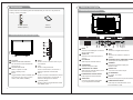
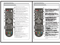
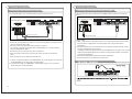
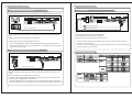
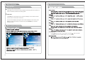
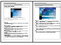
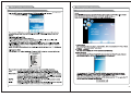
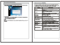
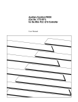
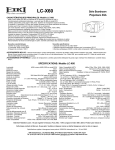
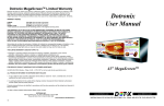
1080p42 LCD TV
Full High Definition LCD TV
1080p42
USER MANUAL
Important Safety Precautions
Important Safety Precautions
CAUTION
RISK OF ELECTRIC SHOCK
DO NOT OPEN
This symbol indicates that this product incorporates
double insulation between hazardous mains voltage
and user accessible parts.
When servicing use only identical replacement parts.
Caution: To reduce the risk of electric shock, do not remove cover (or back). No
user serviceable parts inside. Refer servicing to qualified service personnel.
This symbol indicates important
instructions accompanying the
product.
This symbol indicates "dangerous
voltage" inside the product that
presents a risk of electric shock
or personal injury.
WARNING
To reduce the risk of fire or electric shock, do not expose this product to rain or
moisture.
The apparatus must not be exposed to dripping or splashing. Objects filled with
liquids, such as vases or drinking glasses, must never be placed on the
apparatus.
IMPORTANT SAFETY INSTRUCTIONS
1.
2.
3.
4.
5.
6.
7.
Read these instructions.
Keep these instructions.
Heed all warnings.
Follow all instructions.
Do not use this apparatus near water.
Clean only with dry cloth.
Do not block any ventilation openings. Install in accordance with the
manufacturer's instructions.
8. Do not install near any heat sources such as radiators, heat registers, stoves,
or other apparatus (including amplifiers) that produce heat.
9. Do not defeat the safety purpose of the polarized or grounding-type plug. A
polarized plug has two blades with one wider than the other. A grounding type
plug has two blades and a third grounding prong. The wide blade or the third
prong is provided for your safety. If the provided plug does not fit into your
outlet, consult an electrician for replacement of the obsolete outlet.
10. Protect the power cord from being walked on or pinched particularly at plugs,
convenience receptacles, and the point where they exit from the apparatus.
11. Only use attachments/accessories specified by the manufacturer.
1
12. Use only with the cart, stand, tripod, bracket, or table
specified by the manufacturer, or sold with the apparatus.
When a cart is used, use caution when moving the cart/
apparatus combination to avoid injury from tip-over.
13. Unplug this apparatus during lightning storms or when
unused for long periods of time.
14. Refer all servicing to qualified service personnel.
Servicing is required when the apparatus has been damaged in any way, such
as power-supply cord or plug is damaged, liquid has been spilled or objects
have fallen into the apparatus, the apparatus has been exposed to rain or
moisture, does not operate normally, or has been dropped.
15. If an outside antenna or cable system is connected to the product, be sure the
antenna or cable system is grounded so as to provide some protection
against voltage surges and built-up static charges. Section 810 of the National
Electrical Code, ANSI/NFPA No. 70-1984 (Section 54 of Canadian Electrical
Code, Part 1) provides information with respect to proper grounding of the
mast and supporting structure, grounding of the lead-in wire to an antennadischarge unit, size of grounding conductors, location of antenna-discharge
unit, connection to grounding electrode. See following example.
ANTENNA
LEAD IN
WIRE
ANTENNA
DISCHARGE UNINT
(NEC SECTION 810-21)
ELECTRIC
SERVICE
EQUIPMENT
NEC-NATIONAL ELECTRICALCODE
GROUNDING CONDUCTORS
(NEC SECTION 810-21)
GROUND CLAMPS
POWER SERVICE GROUNDING
ELECTRODE SYSTEM
(NEC ART 250 PART H)
16. Mains plug is used as the disconnect device. It shall remain readily operable
and should not be obstructed during intended use.
This apparatus shall be connected to a mains socket outlet with a protective
earthing connection.
2
User Manual Introduction
Table of Contents
Congratulations on your Kogan LCD TV purchase!
This user manual will help you to setup and operate your Kogan TV set.
Please read this user manual before operating the LCD TV and become familiar
with its features. And keep it for future reference.
Overview of back panel
Overview of remote control
Installing Batteries in the Remote Control
Antenna connection
External Connection
25
28
30
7
8
8
9
10
11
12
12
Connecting DVD Player/Blu-ray Player
13
Connecting DVD Player/Blu-ray Player via HDMI
14
Connecting a Headphone
14
Connecting Digital Audio System
Connecting Amplifier/DVD Home Theater
Connecting PC
Supporting signals
15
Basic operation
Turning the TV On and Off
Input Setup
17
17
18
18
18
19
15
16
16
EPG Menu
Menu system introduction
19
Picture menu options
Sound menu options
Time menu options
19
21
22
3
TV SETTNG operations
LOCK menu operations
5
6
7
Connecting VCR
Channels Selection
Volume Adjustment and Mute Setup
Current Channel Information
23
24
Troubleshooting
Table of Contents
Introduction
Features
Specifications
Accessories
Overview of front and side panel
General Description
Setup menu options
PICTURE menu options
19
4
Introduction
Features
Warnings
Introduction
Specifications
Warnings
l TV adopts 120Hz HD TFT LCD
l
l
l
l
l
Color active matrix LCD display
HDTV compatible(480ip,720p,1080i,1080p)
Connect to computer directly to realize TV/monitor combo.
Zero X radiation complies to green environment protection requirement
16:9 wide screen(480i,480p,720p,1080i, 1080p)
Advanced Chroma Processing
42" / 108cm
1920 x 1080
Fine digital control
l HDMI inputs
l Support SPDIF ouput
AC ~110-240v ,50/60Hz
TV receive system
PAL: D/K, I, B/G; SECAM: D/K, B/G
RF reception range
PAL, NTS 3.58 /4.43, SECAM
75W (Unbalance)
2 x 10W
DC 3V (Two AAA size batteries)
210W
1024 x 328 x 742
22.5Kg
o
o
0C-40C
Note:
1. Keep all original packaging in case you need to return the TV to
Kogan Technologies.
2. In case of any design change, a notice will not be released.
5
6
Accessories
General Description
Please make sure the following items are included with your LCD TV. If any items are
Overview of back panel
missing, contact your dealer.
Remote Control &
Owner’
s
Batteries (AAAx 2)
Instructions
Overview of front and side panel
12
13
③
②
①
7
5
6
11 15
HDMI
Connect to the HDMI jack of a device
with an HDMI output.
VGA/PC IN
Connect to the video output jack on
your PC.
①
SPEAKER
REMOTE CONTROL SENSOR
Aim the remote control towards this
spot on the TV.
POWER INDICATOR
Green: In power on mode.
Red: In standby mode.
INPUT
Toggles between all the available input
sources (DTV, AV1,AV2, S-Video,
YPbPr, VGA, HDMI1, HDMI2)
9
4
7
MENU
Press to see an on-screen menu of your
TV's features.
CH+/Press to change channels.
In the on-screen menu, use the CH +/buttons as up/down arrow buttons.
VOL+/Press to increase or decrease the volume.
In the on-screen menu, use the VOL +/buttons as left/right arrow buttons.
Standby button
Press button to toggle between normal
and standby mode.
PC AUDIO IN
Audio input for external devices.
AUDIO OUT
Connect to the audio output jacks
on your amplifier/home theater.
2
3 8
14
ANT
Connect to an antenna or cable TV
system.
10
11
COMPOSITE & S-VIDEO AUDIO
Audio inputs for external devices.
1
SPDIF
Connect to a Digital Audio devices.
COMPONENT
Connect Component video.
COMPOSITE AV1 VIDEO
Video input for external devices, such
as a camcorder or VCR.
10
COMPOSITE AV2 & COMPONENT AUDIO
Audio inputs for external devices.
S-VIDEO
Connect the S-VIDEO output jack
of DVD or VCR
12
VIDEO-OUT
Connect to the video output
13
AC POWER IN
Ac power in socket
14
PHONE
connect a set of phone for private listening
15
COMPOSITE AV2 VIDEO
Video input for external devices, such
as a camcorder or VCR.
8
General Description
General Description
Overview of remote control
Overview of remote control
6
13
1
3
2
SLEEP
P . MODE
S . MODE
FREEZE
DTV
22
12
1
2
3
SOURCE
4
4
5
6
ZOOM
5
9
10
7
8
9
LIST
0
MENU
RECALL
INFO
11
7
17
23
16
14
15
20
NICAM
FAV
EXIT
EPG
19
8
TTX
MIX
SUBTITLE
TV
RADIO
INDEX
REVEAL
HOLD
SIZE
R
G
Y
C
21
18
POWER: Turns your TV on and off.
S.MODE: Selects audio mode. Press the key
repeatedly to choose one of the modes among
Standard, Music, Moive and Personal.
P.MODE: Selects picture mode. Press the key
repeatedly to choose one of the modes among
Standard, Dynamic, Soft and Personal.
SOURCE: Selects input source.
ZOOM: Change the display mode of the image.
Press the key repeatedly to choose one of the
modes among Normal, Wide, Cinema and Zoom.
Note:
In the VGA mode, you can only choose
“Normal” and “Wide”. In the mode of
“Component”and “HDMI”, you can only
choose the “Wide”, “Cinema”and “Zoom”.
SLEEP: Sets the sleep timer. Press the key
repeatedly to select sleep time among 10, 20, 30,
60, 90, 180, 240, 120, min and off.
INFO: Displays the channel information.
TTX: Press TTX button to enter or exit teletext mode
0~9: Digital keys.
LIST : Press this button to display the channel
list in TV mode
RECALL:To swap to the previous program you
want from current program
DTV: Switches the remote control to TV mode.
MUTE: Mutes the sound.
VOL+/-: Changes your DTV's volume.
CH+/-: Changes channels.
ENTER: Validation key.
MENU: Displays the main menu.
EXIT: Exit the menu.
FAV: Selects favorite channels.
NICAM: The button is used to set NICAM sound syetem.
6
13
1
3
2
SLEEP
P . MODE
S . MODE
FREEZE
DTV
22
12
1
2
3
SOURCE
4
4
5
6
ZOOM
5
7
8
9
RECALL
11
LIST
0
MENU
SUBTITLE
9
10
INFO
INDEX
7
17
23
HOLD:
16
14
15
20
NICAM
FAV
EXIT
EPG
TTX
MIX
SUBTITLE
TV
RADIO
19
8
21
18
31
21
24
25
28
26
INDEX
REVEAL
HOLD
SIZE
R
G
Y
C
29
27
30
EPG:Selects electronic program guide.
FREEZE: This button is used to freeze the
current picture.
ARROW BUTTONS(t/u /▲/▼):Use to move
cursor up/down/left/right.
9
31
TV/RADIO
In the DTV source, press it to enter “Radio”
Channel and press it again. to enter DTV
Channel.
10
General Description
External Connection
Installing Batteries in the Remote Control
Connecting VCR
Installing Batteries
1
These instructions assume that you have already connected your TV to an antenna or a
cable TV system. Skip step 1 if you have not yet connected to an antenna or a cable
system.
Open the battery compartment
cover on the back side.
TV Rear Panel
Battery
Cover
2
Insert two 1.5V AAA size batteries in
correct polarity. Don´t mix old or used
batteries with new ones.
Point the remote towards the remote
control sensor of the wireless TV and
use it within 7 meters.
VCR Rear Panel
Put the used batteries into the recycling bin since it can negatively affect
the environment.
2xsize AAA 1.5V
5 Audio Cable (Not supplied)
3
Closed the cover.
4 Video Cable (Not supplied)
3 RF Cable (Not supplied)
Battery
Cover
Follow the instructions in Viewing a VCR or Camcorder Tape to view your VCR tape.
Each VCR has a different back panel configuration.
When connecting a VCR, match the color of the connection terminal to the cable.
We recommend the use of cables with a Ferrite Core.
Universal Remote Control operation please refer to Appendix 2.
External Connection
Antenna connection
Antenna input impedance of this unit is 75ohm. VHF/UHF 75ohm coaxial cable can be
connected to the antenna jack directly, if the antenna cable is 300ohm parallel flat feeder
cable, you need to use the 300ohm/75ohm converter to connect the antenna cable to the
antenna jack. For details Please refer to the following drawing.
Antennas with 75 W Round Leads
Antennas with 300 W flat twins Leads
1. Unplug the cable or antenna from the back of the TV.
2. Connect the cable or antenna to the ANT IN terminal on the back of the VCR.
3. Connect an RF Cable between the ANT OUT terminal on the VCR and the ANT IN
terminal on the TV.
4. Connect a Video Cable between the VIDEO OUT jack on the VCR and the VIDEO IN
jack on the TV.
5. Connect Audio Cables between the AUDIO OUT jacks on the VCR and the AUDIO L and
AUDIO R jacks on the TV.
If you have a mono (non-stereo) VCR, use a Y-connector (not supplied) to hook up to
the right and left audio input jacks of the TV. If your VCR is stereo, you must connect
two cables.
Use a 75ohm - 300ohm converter
ANT IN
75ohm coaxial cable
300ohm coaxial cable
Antenna cable
Antenna feeder
11
12
External Connection
External Connection
Connecting DVD Player/Blu-ray Player
Connecting DVD Player/Blu-ray Player via HDMI
The rear panel jacks on your TV make it easy to connect a DVD to your TV.
This connection can only be made if there is a HDMI Output connector on the external
device.
TV Rear Panel
TV Rear Panel
DVD Player/Blu-ray Player
DVD Player/Blu-ray Player
2 Audio Cable (Not supplied)
HDMI Cable (Not supplied)
1 Component Cable (Not supplied)
Component video separates the video into Y (Luminance (brightness)), Pb (Blue) and Pr
(Red) for enhanced video quality.
Be sure to match the component video and audio connections.
For example, if connecting the video cable to COMPONENT IN, connect the audio
cable to COMPONENT IN also.
Each DVD player has a different back panel configuration.
When connecting a DVD player, match the color of the connection terminal to the
cable.
We recommend the use of cables with a Ferrite Core.
What is HDMI?
HDMI, or high-definition multimedia interface, is a next-generation interface that enables
the transmission of digital audio and video signals using a single cable without
compression.
Multimedia interface is a more accurate name for it especially because it allows multiple
channels of digital audio (5.1 channels).
The difference between HDMI and DVI is that the HDMI device is smaller in size, has the
HDCP (High Bandwidth Digital Copy Protection) coding feature installed, and supports
multi-channel digital audio.
Each DVD player/STB has a different back panel configuration.
We recommend the use of cables with a Ferrite Core.
1. Connect a Component Cable to the COMPONENT IN [Y, PB, PR] jacks on the TV and
the COMPONENT [Y, PB, PR] jacks on the DVD player.
2. Connect Audio Cables to COMPONENT IN [R-AUDIO-L] jacks on the TV and the
AUDIO OUT jacks on the DVD player.
13
14
External Connection
External Connection
Connecting Digital Audio System
Connecting PC
The rear panel jacks on your TV make it easy to connect a Digital Audio System to your TV.
PC
TV Rear Panel
TV Rear Panel
Digital Audio System
SPDIF
2 PC Audio Cable (Not supplied)
1 D-Sub Cable (Not supplied)
SPDIF Cable (Not supplied)
5.1 CH audio is possible when the TV is connected to an external device supporting 5.1
CH.
We recommend the use of cables with a Ferrite Core.
1. SPDIF jacks on the TV and the Digital Audio Input
jacks on the Digital Audio System. When a Digital Audio System is connected to the
SPDIF terminal: Decrease the gain (volume) of the TV, and adjust the volume level with
the system's volume control.
Each PC has a different back panel configuration.
The HDMI jacks do not support PC connection.
We recommend the use of cables with a Ferrite Core.
1. Connect a D-Sub Cable between RGB/PC IN connector on the TV and the PC output
connector on your computer.
2. Connect a PC Audio Cable between PC AUDIO IN jack on the TV and the Audio Out jack
of the soundcard on your computer.
Connecting Amplifier/DVD Home Theater
Supporting signals
Amplifier/DVD Home Theater
TV Rear Panel
Audio Cable (Not supplied)
Each external input source device has a different back panel configuration.
When connecting an external device, match the color of the connection terminal to the
cable.
We recommend the use of cables with a Ferrite Core.
1. Connect Audio Cables between the AUDIO L and R OUT on the TV and AUDIO IN [RAUDIO-L]on the Amplifier/DVD Home Theater.
When an audio amplifier is connected to the AV OUT [R-AUDIO-L] terminals: Decrease
the gain (volume) of the TV, and adjust the volume level with the Amplifier's volume control.
15
1360X768
1920X1080
16
1
Basic Operation
Basic Operation
Turning the TV On and Off
Menu operation
How to turn the TV on or off
1. Insert the power cord plug into a polarized AC
outlet.
2. Press POWER button on the remote control or
button on the right panel of LCD TV.
3. Normal picture will be displayed on the screen after
6 seconds. If no signal input, "No Signal" will be
displayed on the screen.
4. If temporary POWER off is required, press POWER button on the remote control or
button on the right panel.
5. If you want to completely switch off the power for this unit, unplug the power cord plug
for this unit.
6. After switching off the unit, you should turn on the TV again at least 5 seconds later.
Status indication lamp
Green: In power on mode.
Red: In standby mode.
Auto power-off
If there is no signal input in any Mode, the TV will automatically accesses the standby
state in about 15 minutes.
Memory before turning TV off
The settings of picture and the preset channels will be memorized at turning off the unit.
When being started up again, the unit will work according to the mode set before being
turned off.
1
Input Setup
Press the “SOURCE” button on either the remote control
or the front panel of the LCD TV.
Repeat pressing the “Source” button to select the
desired “source”.
DTV-ATV-AV1-AV2-S-Video-YPbPr-VGA-HDMI1-HDMI2
2 Channels Selection
There are four ways to select channel:
1) Using 0~9, DASH and ENTER keys on the remote control to select channel directly.
2). Using CH+/- key on the remote control or on your TV to select channel.
3) Press LTST key to turn to previous channel, press it again to return to current
channel.
Note: LTST is not activated if no channel has been changed after TV turning on.
4) Select channels from "All Channels List" or "Favorite Channels List".
3 Volume Adjustment and Mute Setup
Volume adjustment
Press VOL+/- key on the remote control or on the TV to display "Volume" menu,
adjust the volume of TV between 0 to 100 by using VOL+/- key:
( To increase the volume, press VOL + key;
( To decrease the volume, press VOL- key;
Mute
Press MUTE key on the remote control to display mute icon on the
left bottom of the screen, and the volume of TV will be turned off, press
MUTE key again to turn on the volume. Mute can be canceled by using
one of the methods below:
( Mute will be canceled if you press MUTE button again.
( Mute will be canceled if you press VOL + key.
17
18
Menu system instruction
Basic Operation
Menu operation
4
Current Channel Information
Press INFO key on the remote control to display the following OSD, the indications of
items in this OSD are listed in the following table.
5
EPG Menu
Press EPG key to enter "EPG" menu, the first line displays current channel number
channel name, event title and current time.
The second line displays all programs which will be displayed in this channel, press
t/u key to select the program you desired, then press ENTER key to enter this
program to watch.
Menu system instruction
Temp
ENTER
Aspect Ratio
Press
button to select Aspect Ratio the press
button to select
(Available video size: ZOOM2-ZOOM1-16:9-4:3-AUTO)
19
20
Menu system instruction
Menu system instruction
SOUND
▲/▼
SOUND
ENTER
SOUND
Time menu options
▲/▼
t/u
▲/▼
t/u
▲/▼
t/u
Auto Volume
▲/▼
Sound
▲/▼
21
t/u
Auto Volume
t/u
22
Menu system instruction
Menu system instruction
Picture menu options
Picture menu options
u
Press the MENU button on the front panel of the LCD TV or on the remote control,
and t / u then use buttons and ENTER to select the setup menu.
1.Press the ▲/q button to move the cursor to the item to be selected.
2.Press the t / u button to make adjustments.
3.When you are satisfied with your adjustments, press the MENU or EXIT
button to exit the main menu.
Adjust
▲/q
ENTER
offset
▲/q
t /u
offset
▲/q
t /u
Size
▲/q
▲/q
23
t /u
Size
t /u
24
Menu system instruction
Menu system instruction
TV SETTNG operations
TV SETTNG operations
2) ATV Manual Tunint
ATV Manual Tunint
1)Auto Tving
Auto Tving
25
26
Menu system instruction
Menu system instruction
DTV Manual Tuning
LOCK menu operations
DTV Manual
Tuning
8888.
DELETE
27
SKIP
FAV
28
Menu system instruction
Troubleshooting
LOCK menu operations
MUTE
8
29
30