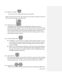
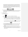
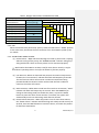
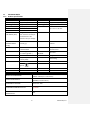
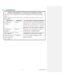
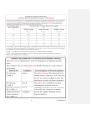
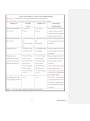
1
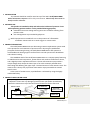
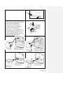
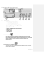
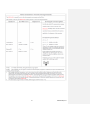
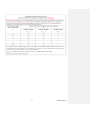
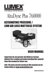
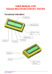
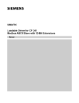
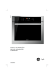
ELITE/SAVVY 8000 Series ® Air Mattress System User Manual Air Kinetic Technologies Corp. TEL: +886-3-4194567 FAX:886-3-4693789 Address:No. 3, Gongye 5thRd., Pingzhen 324, Taoyuan, Taiwan http://www.aktc.com.tw 1 GDxxx-xxx/Rev.A IMPORTANT SAFEGUARDS READ ALL INSTRUCTIONS BEFORE OPERATING THIS DEVICE NOTE, CAUTION AND WARNING STATEMENTS: NOTE –Indicate some tips CAUTION – Indicate correct operating or maintenance procedures in order to prevent damage to or destruction of the equipment or other property WARNING – Call attention to a potential danger that requires correct procedures orpractices in order to prevent personal injury. WARNING– To reduce the risk of electrocution 1. Always unplug this product immediately while it’s not in use. 2. 3. 4. 5. Do not disassemble the pump to avoid electrocution Do not place or store product where it can fall or be pulled into a tub or sink. Do not place in or drop into water or other liquid. Do not use while bathing. Do not reach for a product that has fallen into water. Unplug immediately. WARNING – To reduce the risk of burns, electrocution, fire or injury to persons 1. The operation of the system has to have the mattress connected to the PUMP, please do not power-off or unplug the PUMP in operation. 2. This product should never be left unattended when plugged in. 3. Close supervision in necessary when this product is used by, on, or near children or invalids. 4. Use this product only for its intended use as described in this manual. Do not use attachments not recommended by the manufacturer. 5. Never operate this product if it has a damaged cord or plug, if it is not working properly, if it has been dropped or damaged, or dropped into water. Return the product to a service center or to the distributor for examination and repair. 6. Keep the cord away from heated surfaces. 7. Never block the air openings of this product or place it on a soft surface, such as a bed or couch, where the openings may be blocked. Keep the air opening free of lint, hair, and other similar particles. 8. Never drop or insert and object into any opening or hose. 9. Connect this product to a properly grounded outlet only. See Grounding Instruction. 10.Put the power cord or hose tube at the patient foot area to avoid wound on the patient’s head. 11.To avoid electromagnetic interference, the patient environment should not have 2 GDxxx-xxx/Rev.A strong electro-magnetic or RF generated equipment near by 12.The PUMP will have minor heat generated in operation, please do not direct contact the surface continuously for more than 1 minute. 13.The product with ground pin (3 pin type) cannot be used in the home. 14.The EMC specification is compliant with the regulation requirement (please reference to the EMC information at the last page). For power cord with ground pin (3 pin type), the connection with properly grounded power outlet would get a better EMC suppressing effect. The system will work correctly also for the power cord connection with the power outlet without grounding. 15.When loss or failure of the supply mainstemporarily(In 20 minutes). It causespump stop, fail of power indication and alarm. But these are normal. The product can return to work state after supply mains is stable. SYMBOLS DESCRIPTION I POWER ON O POWER OFF ATTENTION DOUBLE ISOLATION “BF” SYMBOL, INDICATE THIS PRODUCT IS ACCORDING TO THE DEGREE OF PROTECTION AGAINST ELECTRIC SHOCK FOR TYPE BF EQUIPMENT CAUTION, READ THE INSTRUTION BEFORE USE AWAY FROM THE FLAME IP21 WATER AND DUST PROTECTION CLASSIFICAITON FUSE SPECIFICATION DISPOSAL OF ELECTRICAL & ELECTRONIC EQUIPMENT(WEEE): THIS PRODUCT SHOULD BE HANDED OVER TO AN APPLICABLE COLLECTION POINT FOR THE RECYCLING OF ELECTRICAL AND ELECTRONIC EQUIPMENT. UL CERTIFICATION LOGO (COMPLIACE WITH IEC60601-1) With respect to electrical shock, fire and mechanical hazards only in accordance with STANDARD. CB CERTIFICATION LOGO 3 GDxxx-xxx/Rev.A CE CERTIFICATION LOGO Contents 1 2 3 4 5 6 7 8 9 10 11 INTRODUCTION ............................................................................................................................ 5 INTENDED USE .............................................................................................................................. 5 PRODUCT DESCRIPTION ............................................................................................................... 5 PRODUCT INSTALLATION GUIDE ................................................................................................... 5 PANEL DISPLAY AND THE OPERATION GUIDE ............................................................................... 8 CLEANING ................................................................................................................................... 13 STORAGE ..................................................................................................................................... 14 MAINTENANCE ........................................................................................................................... 14 The Disposal of Air Mattress ...................................................................................................... 14 TROUBLESHOOTING ................................................................................................................... 15 TECHNICAL DATA ........................................................................................................................ 16 4 GDxxx-xxx/Rev.A 1 INTRODUCTION This manual should be used for initial set up of the AKTC ELITE/SAVVY 8000 Series®Air Mattress System and for daily maintenance. Please keep the manual in handy area for reference. 2 INTENDED USE This product is intended to help and reduce the incidence of pressure ulcers while optimizing patient comfort. It also provide following purposes: Individual home care setting and long-term care of whom suffering from pressure ulcer. Pain management as prescribed by physician. NOTE: Equipment not suitable for use in the presence of a flammable anesthetic mixture with air or with oxygen or nitrous oxide. 3 PRODUCT DESCRIPTION The ELITE/SAVVY 8000 Series are alternating mattress replacement system used in the prevention and treatment of pressure ulcers. By using the established principles of alternating therapy, the ELITE/SAVVY 8000 Series offer patients a comfortable and relaxing support surface which can both prevent skin breakdown and enhance healing. The CONTROL UNIT of the ELITE/SAVVY 8000 Series is a compact pump featuring an audible and visual low pressure, power failure and machine malfunction alarms, and a digital pressure adjustment function. The 19 cells mattress unit provides a unique design which keeps the lower layer of air cells constantly inflated while alternating and deflating the upper layer. The head section of cells remains static. The mattress has a heavy-duty nylon base sheet with a vapor permeable PU coated stretch cover. In the event of cardiac arrest, rapid deflation is achieved by using the highly visible CPR facility. 4 PRODUCT INSTALLATION GUIDE 1. Unpacking the box to inspect for any damage, which may have occurred during shipment. If there are any damages, please contact your dealer immediately. 2. Place the mattress on top of the bed frame. Please note for the foot end. Formatted: Font: 14 pt, Complex Script Font: +Body (Calibri), 14 pt Air Mattress Patient Head Serial No. (inside the cover) CPR PUMP Unit Hose Connector 5 GDxxx-xxx/Rev.A 3. Fix the mattress onto the bed frame Elastic belt, or Ribbon 4. Hang the pump onto bed rail (food-end), the hangers will hold the bed rail tight automatically 5. Unplug the cover of the hose connector and connect the hose connector to the pump unit. Note: There’s 4 combinations of hose connectors vs. the pumps’ side panel as following (GD210, GD211, GD310, GD311), make sure you hear the click sound at connection. GD210 4 5 GD310 Follow the alignment mark for connection. GD211 Follow the alignment mark for connection. GD311 Follow the direction for connection. 6 Follow the direction for connection. GDxxx-xxx/Rev.A 6. Plug the power cord into electrical outlet NOTE: Make sure the pump unit is suitable for the local power voltage CAUTION: The pump can only be applied to the mattress recommended by the manufacturer. Do not use it for any other purpose (applied part: air mattress) 7. Make sure the CPR is at CLOSE position before turning on the power. Switch the CPR to OPEN position to release the air at emergency or for packaging CPR Position Indicator 8. Put on the hose connector cover at transportation, the mattress will retain pressure for up to 24hrs GD210 After GD310 After Before putting on the cover Before putting on the cover GD211 GD311 No direction for the cover 7 No direction for the cover GDxxx-xxx/Rev.A 5 PANEL DISPLAY AND THE OPERATION GUIDE 1 2 7 8 5.1 6 5 4 3 PANEL DISPLAY ① Alarm Mute and Alarm Indicator Low Pressure Alarm Indicator Power Failure Alarm Indicator Service (Malfunction) Alarm Indicator ② Alternate Cycle Time or Warning codeDisplay ③ Operating or Standby ④ Auto-Firm ⑤ Function Mode Selection (Alternate & Static) ⑥ Panel Lock-out ⑦ Comfort Control ⑧ Auto Detection 5.1.1 ALARM MUTE Press alarm mute button to temporary suspend theLow-Pressure/Power Failure/Static Overtime /Service alarms. Should the situation not resolvedand the fault conditions continue, the alarm shall resume notifying the patient/caregiver. 5.1.2 Alternate CycleTime Display Alternating Cycle Time can be selected from 10~30mins at 5mins interval by pressing the CYCLE button 8 GDxxx-xxx/Rev.A 5.1.3 Operate or Standby Press this button to start operating or go into standby. NOTE: The power switch on the side of pump must be turned on.At Power on the unit will resume the state before last power-off. 5.1.4 Inflate/Auto-Firm The PUMP will go into the Inflate mode (LED lights flashing) every time theOPERATEmode is triggered. This insures the mattress to be able to reach its maximum operating pressure. Once the max pressure level is reached, the pump will automatically switch into the previous selected mode and comfort level. User can also use this function as full mattress inflation during patient sit-up or ingress/egress for better support. 5.1.5 Function Mode Switch ALTERNATE - for the mattress to operate at alternating mode the air cell of the mattress will be proportionally deflated to reduce the surface pressure. The alternating cycle will continue at the selected cycle time until another mode is selected. STATIC - This mode allows the mattress to maintain at the selected pressure. After 20 minutes, the STATIC OVER TIME alarm will be triggered for 10mins at every 15 seconds interval. Without further action, the PUMP will go into ALTERNATE mode automatically. 5.1.6 Panel Lock-Out Should the panel remain untouched for 30 seconds or press the Lock-out button, the lock-out feature will lock the screen to prevent accident from changing the setting without notice. To unlock, press the Lock-out button for 3 seconds. 5.1.7 Comfort Level Comfort level controls the air pressure output. When pressing the FIRM button, 9 GDxxx-xxx/Rev.A the output pressure will increase and higher pressure output will support the heavier weight user, for decreasing air pressure, vice versa.Check to see if the suitable pressure is selected by sliding one hand between the air cells and the patient to feel patient’s buttocks. Users should be able to feel the minimum contact. Always leave at least 1 inch space between user’s buttock areas and air cells under to prevent bottoming out. 5.1.8 Auto Detection When pressing the SOFT and FIRM button together, the pump will automatically detect the weight of the patient and set the appropriate pressureoutput for patient comfort. 5.2 OPERATION GUIDE 5.2.1 GENERAL OPERATION: NOTE: Press The power switch is locatedon the side of pump to turn on the unit,all indicatorson the control panel will light up accompanied with a beep for 2 seconds (You can also check the indicator for failure if any), and the indicator of STANDBY on the control panel will light up (In case the pump was turning off at OPERATE, it will go to OPERATE directly). Ps: To test if the battery is working properly, press to turn off the power. Power failure alarm should be triggered. If not, please call customer service. Push on the OPERATE button , the system will start inflation andthe "AUTO-FIRM" indicatorwill be flashing. Themattress shoud be fully inflated within 60 minutes, and automatically enter the last operating mode, otherwise the low pressure alarm will be triggered. According to the weight of the patient, adjust the pressure setting to the most suitable level without bottoming out.User can determine an appropriate pressure by adjusting the Comfort Level. Please consult with your physicianfor a proper setting. 10 GDxxx-xxx/Rev.A Table 1 Weight and Comfort Level Reference Table GDseries pump+8”mattress (iLAL/2-1Alternate) Patient Weight (KG) Comfort Control Pump output 20 40 60 80 100 120 140 160 180 (Auto-Detection) Pressure(mmHg) ●●●●●●●● 25 < 40 ●●●●●●●● 30 20~60 ●●●●●●●● 35 40~80 ●●●●●●●● 40 60~100 ●●●●●●●● 45 80~120 ●●●●●●●● 50 100~140 ●●●●●●●● 55 120~160 ●●●●●●●● 60 140~180 5.2.2 CPR When CPR needs to be performed, quickly rotate the CPR valve to “OPEN” position, at the same time, disconnect the hose connector from the PUMP to speed up the air release. 5.2.3 AUDIBLE AND VISIBLE ALARM (1) Power Failure – When electrical shortage occurred or power cord is unplug without turning off the pump, the “POWER FAILURE” indicator will light up along with buzzer. Check to ensure power cord is connected properly NOTE: When the PUMP is not been used for more than 3 months, it might need 6hours operating time or more for the Alarm to function properly. (2) Low Pressure –When an abnormal low pressure occurred in body section for4mins,the "Low Pressure" indicator will flash and beepevery 4 seconds. The Low Pressure alarm will continue until alarm mute button being pressed.Should the situation not be resolved and the fault conditions continue, the alarm will resume. (3) Static Overtime –When Static mode lasts for more than 20 minutes, "Static" indicator will flash and beep every 15 seconds. Press the MODE key to change to alternating mode can disable the alarm, or press the MUTE button to pause the alarm for 20 minutes. If not dealt, the system will automatically enter into alternating mode after 10 minutes. (4) Power Failure Overtime – When the power is lost for more than 20mins, the “Power Failure” indicator will flash along with a beep sound at every 15 seconds, Press the MUTE button to cease the alarm, and check the patient for bed sore examination. 11 GDxxx-xxx/Rev.A (5) Service(Malfunction)–When fault conditions occur, the "SERVICE" indicator will light up along with buzzer. Reference to Table 2 for Warning code and call the agent or distributor for service. Table 2 WarningCode Reference Table PRIORITY HIHG WARNINGCODE ↓ LOW 0 N/A 1 2 INDICATOR LED AUDIBLE CONDITION OF OUTPUT MODE OUTPUT N/A ONCE Power Failure ONCE WARNING DESCRIPTION Not in System Shutdown Key Tone POWER-OFF System Shutdown OPERATE OR STANDBY OPERATE OR STANDBY Key Tone from Functional Button ALL LED ONCE N/A ONCE 4 AutoFirm ONCE OPERATE Mattress Inflation Completion Inflation Ended 5 AutoFirm ONCE OPERATE Auto-Firm Completion Auto-Firm Ended 6 Static ONCE OPERATE Static Completion Static Ended POWER-OFF Power Failure Alarm No Display OPERATE OR STANDBY OPERATE OR STANDBY OPERATE OR STANDBY OPERATE OR STANDBY OPERATE OR STANDBY OPERATE OR STANDBY OPERATE OR STANDBY OPERATE OR STANDBY OPERATE OR STANDBY OPERATE OR STANDBY OPERATE OR STANDBY OPERATE OR STANDBY FACTORY CALIBRATION MODE FACTORY CALIBRATION MODE Power-On Inflation FailureAlarm 3 7 N/A N/A Power Failure REPEAT (cycle4sec.) REPEAT (cycle4sec.) REPEAT (cycle4sec.) REPEAT (cycle4sec.) REPEAT (cycle4.5sec.) REPEAT (cycle4.5sec.) REPEAT (cycle4.5sec.) REPEAT (cycle4.5sec.) REPEAT (cycle4.5sec.) REPEAT (cycle4.5sec.) REPEAT (cycle15sec.) REPEAT (cycle15sec.) REPEAT (cycle15sec.) 8 Low Pressure 9 Low Pressure 10 Low Pressure 11 Service 12 Service 13 Service 14 Service 15 Service 16 Service 17 Power Failure 18 Service 19 Static 20 NONE NONE 21 NONE NONE Power-On REMARKS All Indicators Light On State/Mode Switching Auto-Firm Failure Alarm Low Pressure Overtime Alarm Constant Pressure Control Failure Alarm High Pressure Overtime Alarm Low Ambient Temperature Alarm High Ambient Temperature Alarm Air Valve 1 Positioning Failure Alarm Air Valve 2 Positioning Failure Alarm Environment Temperature Over Specification Limit Environment Temperature Over Specification Limit Air Valve 1 failure Air Valve 2 failure Power Failure Overtime Alarm Battery Low Alarm Battery would need to be replaced Static Overtime Alarm Calibration Not Completed Calibration Completed 5.2.4 ALARM MUTE When alarms were triggered, both the LED light and buzzer will sound off to warn the patient/caregiver. By pressing the button, it will temporary mute the buzzer so the caregiver may check for possible causes. Should the situation not resolved 12 GDxxx-xxx/Rev.A andfault conditions continue, the alarm will resume. When in Power Failure situation, pressing alarm mute will cease the buzzer and turn off the “Power Failure” indicator. 6 CLEANING By wiping the PUMP UNIT with a damp cloth pre-soaked with a mild detergent, and keep it away from dust. If other detergent is used, choose one that will have no chemical effects on the surface of the plastics case of the pump unit. CAUTION: Do not immerse or soak pump unit. By using a single use wipe, clean the MATTRESS COVER with a solution of neutral detergent and hand hot water. Rinse thoroughly with clean water and a damp single use wipe. Disinfecting the cover If the cover is heavily soiled or has been exposed to bodily fluids such as blood, it will require a more thorough cleaning procedure. Wipe the cover using a single use wipe and a 0.1% Chlorine Solution (1,000ppm) and cold water. If required a 1% Chlorine Solution (10,000ppm) and cold water can be used. Rinse thoroughly with clean water and a damp single use wipe. Make sure the cover is completely dried before refitting to the mattress. Frequent or prolonged exposure to higher concentration disinfectant solutions may prematurely age the fabric cover of mattresses. Surfaces must be protected during use and rinsed and thoroughly dried after application of a disinfectant. Laundering Before laundering mattress covers should be completely removed. Where required mattress covers can be laundered as follows: Pre wash 60℃+ 15 minutes Main wash 60℃+ 15 minutes This should be followed by a cold rinse and extraction. Drying Mattress covers should be hung from a line or bar and drip dried in a clean indoor environment. Covers must be completely dried before refitting to the mattress. Mattress covers can be tumble dried on a low heat setting for 90 minutes. Drying 13 GDxxx-xxx/Rev.A temperature must not exceed 40℃. Exceeding the temperature can cause significant damage to the mattress cover. CAUTION: Do not use phenolic-based product for cleaning. CAUTION: After cleaning, dry the mattress without direct exposure of sunlight. 7 STORAGE To quickly vacuum air out from mattress for storage, rotate the CPR valve to OPEN position and disconnect the hose connector to release the air. Lay the mattress out flat and upsides down. Roll from the head end towards the foot end Foot-end strap can then be stretched around the rolled mattress to prevent unrolling The power cord could be wrapped around the pump bumper or disconnected for storage. 8 MAINTENANCE 8.1 8.1 General Check main power cord and plug if there are abrasions or excessive wears. Check mattress cover for signs of wear or damage. Ensure mattress cover and tubes are stubbed together correctly. Check the air hoses for any kink or break. For replacement, please contact your local dealers. 8.2 8.2 FUSE REPLACEMENT Disconnect the plug from mains power when a blown fuse is suspected. Remove the cover of the fuse holder by means of a small screwdriver. Insert a new fuse of the correct rating in, and replace the cover of the fuse holder back. The fuse rating should comply with the requested specification. 8.3 8.3 AIR FILTER REPLACEMENT Replace the air filter located at the back of the pump. The filter is reusable and can be washed gently with a mild detergent and water. Dry the filter before use. Check and replace air filter regularly if environment is dirty. 9 The Disposal of Air Mattress When the air mattress is broken or no longer be useable, the mattress and the pump may be discard for recycle. 14 GDxxx-xxx/Rev.A 10 TROUBLESHOOTING PROBLEM SOLUTION The mattress is not able Check if the mattress model (model no. located inside the to connect with the cover at the foot end)xxAAAxxx matched with the PUMP PUMP model xxBBB-xxx. The AAA should be the same as BBB. If not, please contact with the agent or distributor Check if the connector cover is removed and make sure the connector is not broken The pump is showing Check if the plug is connected to mains no indications it is Check if the main power switch is at ON position working Check if there is any blown fuse Power Failure Alarm The pump is in operation but the power failure alarm is Failure not working at power down, please call customer service The low pressure light Check if the CPR is at CLOSE position is constantly flashing Check if the power was suddenly shut down and the alarm is Check if the connection between air tube to pump unit is sounded tightly secured Check if all coupling connections along mattress are secured Power Failure Alarm If the PUMP is in operation but failed to trigger the Power Failed Failure Alarm at Power Off, please contact the dealer or agent for further investigation The pump is on but Make sure the mattress inflationis completed the mattress is not Check the pump control panel the indicator of alternated “ALTERNATE” is lighted on, if not, switch it to “ALTERNATE” Check if “Service” alarm indicator is on with buzzer, if yes, contact the dealer or agent for further investigation The pump is operating Make sure the pump is resting against a solid surface noisily If the noise getting louder, contact the dealer or agent for further investigation Patient is bottoming Pressure setting might be inadequate for the patient, adjust out (without alarm comfort level to FIRM and wait for a few minutes for better triggered) comfort If the above information does not solve the problem, please contact your localdealer or agent for further support. 15 GDxxx-xxx/Rev.A 11 TECHNICAL DATA 11.1 Product Specification PUMP UNIT AIR MATTRESS 8”Mattress Series MODEL GD Series Pump MODEL DIMENSION(cm) 33 (W) x 22 (D) x12 (H) DIMENSION(cm) 89 (W) x 200 (L) x 21 (H) WEIGHT(kg) 3.5kg WEIGHT(kg) 10Kg CYCLE TIME 10/15/20/25/30minutes CELL MATERIAL STATIC TIME 30 minutes AUTO FIRM TIME 20 minutes PUMP OUTPUT FLOW RANGE (Liter) > 8L (@120V or 230V) Note: The flow rate may be varied because of the fluctuation of input voltage PUMP OUTPUT PRESSURE RANGE (mmHg) Nylon TPU or TPU film NO. OF AIR CELL 25 to 60 (±2) 19 CELLS POWER AC120V 60Hz or AC230 V 50Hz COVER MATERIAL 2Way Stretched Polyester with PU coated CURRENT 0.25 AMAX (@132V~) or 0.12AMAX (@253V~) BOTTOM MATERIAL Nylon-TPU FUSE RATING T1AL 250VAC MAX WEIGHT 180kg FREQUENCY 60Hz (120V) or 50 Hz (230V) MAX PRESSURE CLASSIFICATION Class II 103.5 mmHg Type BF WARRANTY 2 years WARRANTY 1 year SHELFLIFE 2 years SHELFLIFE 1 year ENVIRONMENTAL CONDITIONS OPERATION ENVIRONMENT 5℃~40℃ 15%RH ~ 93%RH(no condensation) STORAGE ENVIRONMENT -25℃~70℃ ≦93%RH(no condensation) ENVIRONMENT PRESSURE 70 kPa-101.3kPa ENVIRONMENTHORIZONTAL LEVEL ≦3000m WATER AND DUST PROTECTION CLASSIFICAITON IP21 16 GDxxx-xxx/Rev.A 11.2 EMC INFORMATION 17 GDxxx-xxx/Rev.A 18 GDxxx-xxx/Rev.A 19 GDxxx-xxx/Rev.A 20 GDxxx-xxx/Rev.A 21 GDxxx-xxx/Rev.A 22 GDxxx-xxx/Rev.A 23 GDxxx-xxx/Rev.A