1
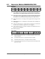
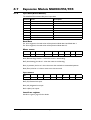
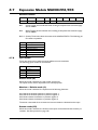
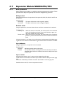
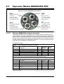
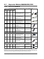
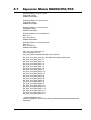
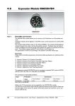
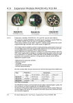
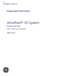
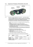
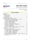
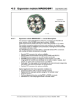
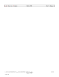
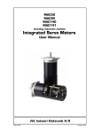
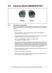
4.7
4.7.1
Expansion Module MAC00-FP2/FP4
MAC00-FP2
MAC00-FP4
With cable glands
With M12 connectors
TT1010GB
Profibus module MAC00-FP2 and FP4 Introduction
The MAC00-FP2 and FP4 are Profibus-DP slaves. They are capable of running at Baudrates up to 12Mbit.
All the registers1 of the MAC motor can be read and written.
The modules include 6 inputs, 2 of which are end-limit inputs. These can be read from
the Profibus-DP. The end-limit inputs can automatically halt the motor. The other inputs
can be used to activate different movements.
The MAC motor is controlled by writing to the input data (9 bytes).
The expansion modules MAC00-FP2 and FP4 can be mounted on standard MAC motors
MAC50, MAC95, MAC140, MAC141, MAC400 and MAC800.
Both modules offer the same functions but with the following hardware differences:
Type
Protection
class
Connectors
I/O and interface
Power supply
Bus interface
MAC00-FP2
IP67/IP65*
Cable glands
(Mini crimp connectors internally
Cable glands
(Screw terminals
internally)
Cable glands x 2
(Screw terminals
internally)
MAC00-FP4
IP67/IP65*
M12
M12
M12 B-coded (x2)
Note*: IP65 on MAC400-800
Both modules are delivered without any cables as standard.
Optionally the MAC00-FP2 module can be delivered with cable in selected lengths. Also
cables for the MAC00-FP4 with M12 connectors are available.
The first part of this section deals with the common features of both modules. Please see
the latter pages for specific information about each module, such as example connection
diagrams.
1
2
232
A list of the typically used registers can be found in Serial Quick Guide (MacTalk protocol), page 357.
The FlexMac commands are described in FastMac commands, page 240.
JVL Industri Elektronik A/S - User Manual - Integrated Servo Motors MAC050 - 3000
4.7
Expansion Module MAC00-FP2/FP4
4.7.2
MAC00-FP2 and FP4 Address and Termination setup
Each unit connected to the Profibus must be set up with a unique address.
The illustration below shows how the address and termination can be set on the internal
dip switch. The dip switch is located on the internal circuit board.
MAC00-FP2 and FP4 Dip switch settings
Please notice that in newer modules
with firmware 3.01 or newer the address
Mini dip-switch
can only be set by software
OFF
Dip 1-7 - Address setting
(address range 0-127)
Dip 8 - Address set by software
Dip 9-10 - Line termination
Both set to ON =
Term. enabled
Both set to OFF =
Term. disabled
Rear side of the MAC00-FP2 or FP4
expansion module
ON
1
2
3
4
5
6
7
8
9
0
SW1
Notes.
SW1 default setting: All switches set to “ON”
except 9+10 which are “OFF” which corresponds to
- Address is set by software / - Termination disabled
“Address set by software” (DIP8) means that
the profibus address will automatically be set
to the same value as the motor address
Dip switch location on the
MAC00-FP2 Expansion module
Cable glands
Basic MAC motor
housing
Internal circuit boards
Profibus and I/O
connectors.
Dip Switch placed
on the rear side of the
module
TT0946GB
Important: On newer modules with firmware 3.01 or 3.02 the dip switch 1 to 8 has
been disabled and the address can only be set in software by using for example MacTalk.
Please contact your JVL distributor if it is crucial to use the dip switch for address setup.
JVL Industri Elektronik A/S - User Manual - Integrated Servo Motors MAC050 - 3000
233
4.7
Expansion Module MAC00-FP2/FP4
4.7.3
Output data (Master->Slave)
The MAC00-FP2/FP4 module contains 9 bytes of output data.
Address
Name
Description
0
Write data 3 (MSB)
Data to write to register
1
Write data 2
--- “ ---
2
Write data 1
--- “ ---
3
Write data 0 (LSB)
--- “ ---
4
Write register selector
The register to write
5
Read register selector
The register to read
6
Direct register
Direct FlexMac command
7
Command
Bits for commanding reads/write
8
Input setup
Bits for input setup
Write data
For 16 bit registers, the data must be placed in Write data 0 and Write data 1.
For 32 bit registers, the data must be placed in Write data 0-3.
Write register selector
The number of the register to write to should be placed here. The register must be in
the range 1-255.
Read register selector
The number of the register to read from should be placed here. The register must be in
the range 1-255.
Direct register
This register can be used to execute a FlexMac2 command. When writing to this
Register, the command will be executed immediately. The bit 0-6 is the command, and
bit 7 is not used. If the same command is to be executed twice, bit 7 can be toggled.
The command is accepted when the “Last direct register”, in the input data, has the same
value as this register.
234
JVL Industri Elektronik A/S - User Manual - Integrated Servo Motors MAC050 - 3000
4.7
Expansion Module MAC00-FP2/FP4
Command
Bit
7
6
5
4
3
2
1
0
Function
Write
Toggle
Read
Toggle
Write
32 bit
Read
32 bit
Auto
write
Auto
read
Reserved
Reserved
Bit 7 (Write toggle) is used for writing data to the selected register (Write register selector). When this bit is toggled, writing is executed. The write command is accepted when Bit 7 in the command status (output data byte 7) is equal to this bit.
Bit 6 (Read toggle) is used for reading data from the selected register (Read register selector). When this bit is toggled, reading is executed. The read command is accepted when Bit 6 in the command status (output data byte 7) is equal to this bit.
Bit 5 (Write 32 bit) Set this to 1 if writing to a 32 bit register and 0 if writing to a 16 bit
register.
Bit 4 (Read 32 bit) Set this to 1 if reading from a 32 bit register and 0 if reading from a
16 bit register.
Bit 3 (Auto write) When this bit is 1, the data written in write data 0-3, is transferred to
the MAC motor immediately, regardless of the write toggle bit.
Bit 2 (Auto read) When this bit is 1, the data in read data 0-3 is updated all the time, regardless of the read toggle bit.
Bit 1and Bit 0 should be 0.
Input setup
Bit
7
6
5
4
Function
-
Reset end limit
PL Enable
NL Enable
3
2
1
0
Input mode
Bit 6
(Reset end-limit) When this bit is 1, the end limit condition is reset, if no end
limits are activated.
Bit 5
(PL Enable) When this bit is 1, the positive end-limit is enabled.
Bit 4
(NL Enable) When this bit is 1, the negative end-limit is enabled.
Bit 3-0
(Input mode) these bits select the current input mode. See section Input modes,
page 238 for details.
JVL Industri Elektronik A/S - User Manual - Integrated Servo Motors MAC050 - 3000
235
4.7
4.7.4
Expansion Module MAC00-FP2/FP4
Write to a register example
If a new velocity need to be written to the motor it is done after this step by step procedure.
1. Write the new speed value to the 4 databytes (32 bits) on address 0 to 3.
2. Setup the register number where the data must be written to.
In this case its the velocity register which is register 5 so this number must be written
into the “write register selector” address 4.
3. In the “Command” register at address 7 the “Write 32bit” and the “Write toggle”
must be toggled.
4. Wait until the “Write toggle” bit in the “Command status” register is the same as the
“write toggle” in the “Command” register. Only when they are equal the write cycle
is completely finished.
Definitions:
Toggle: Change to opposite state. (from 0 to 1 or from 1 to 0). On bit level it correspond
to making an inverse of the bit.
236
JVL Industri Elektronik A/S - User Manual - Integrated Servo Motors MAC050 - 3000
4.7
Expansion Module MAC00-FP2/FP4
4.7.5
Input data (Slave->Master)
The MAC00-FP2/4 contains 8 bytes of input data.
Address Name
Description
0
Read data 3 (MSB)
Data read from register
1
Read data 2
--- “ ---
2
Read data 1
--- “ ---
3
Read data 0
--- “ ---
4
Motor status
Status bits for the motor
5
Input status
Status of inputs
6
Last direct register
Last accepted direct FlexMac command
7
Command Status
Status bits for commands
Read Data
For 16 bit registers, the read value will be placed in Read data 0 and Read data 1.
For 32 bit registers, the read value will be placed in Read data 0-3.
Motor status
Bit
7
6
5
4
3
Function
-
Decelerating
Accelerating
In position -
2
1
0
-
-
Error
Bit 6 (Decelerating) this bit is 1 when the motor is decelerating.
Bit 5 (Accelerating) this bit is 1 when the motor is accelerating.
Bit 4 (In position) this bit is 1 when the motor has reached its commanded position.
Bit 0 (Error) this bit is 1 when a motor error has occurred.
Input status
Bit
7
6
5
4
3
2
1
0
Function
-
-
PL
NL
IN4
IN3
IN2
IN1
Bit 5 (PL) Positive limit input.
Bit 4 (NL) Negative limit input.
Bit 3-0 (INx) user inputs.
Last direct register
See Direct register, page 234 for details.
JVL Industri Elektronik A/S - User Manual - Integrated Servo Motors MAC050 - 3000
237
4.7
Expansion Module MAC00-FP2/FP4
Command status
Bit
7
6
Function
Write Toggle Read Toggle
5
4
-
-
3
2
1
0
Status
Bit 7
(Write Toggle) this bit indicates when writing is completed. See Command, page
235 for details.
Bit 6
(Read Toggle) this bit indicates when reading is completed. See Command, page
235 for details.
Bit 3-0 (Status) These bits indicate the status of the MAC00-FP2/FP4. The following sta
tus codes are possible:
4.7.6
Code
Description
0
OK – Idle
1
Executing Input
2
Executing Output
3
Limit switch active
4
Profi error
5
Connecting to MAC motor
Input modes
The 4 user inputs can be used to execute different move commands.
The following input modes can be selected:
Mode
Description
0
Passive
1
Absolute+Relative
2-14
Reserved
15
Custom
Passive mode (0)
When this mode is selected, the user inputs are ignored.
The inputs can be read in output data 5 for other purposes.
Absolute + Relative mode (1)
When this mode is selected. the inputs have the following functions:
IN1: Selects the absolute position in position register 1.
IN2: Selects the absolute position in position register 2.
IN3: Moves relative the distance in position register 3.
IN4: Moves relative the distance in position register 4.
The action is executed when an inactive-to-active transition is detected on the input.
Custom mode (15)
When this mode is selected, the action of each input can be selected with the slave parameters. See Slave parameters, page 239.
238
JVL Industri Elektronik A/S - User Manual - Integrated Servo Motors MAC050 - 3000
4.7
Expansion Module MAC00-FP2/FP4
4.7.7
Slave parameters
When configuring the profibus, it is possible to set some parameters for the slave. These
parameters are setup during startup and cannot be changed during operation.
XX Input level
Using these parameters, the input level of the inputs IN1, IN2, IN3, IN4, NL and PL can
be selected.
Possible values:
Active high
Active low
: The input will be active, when a signal is applied.
: The input will be active, when no signal is applied.
End-limit action
Using this parameter, the action taken when an end limit is activated can be selected.
Possible values:
Velocity = 0 :
When the end-limit is activated, the velocity will be set to 0 and the
motor will decelerate and stop. If the motor should run again, the
user must manually set a new velocity.
Passive mode : When the end-limit is activated, the actual mode will be changed to
passive. In passive mode the motor is short-circuited and can be rotated.
In firmware version 1.4 or higher, the “end-limit action’ is also active if the Profibus is going off-line but it needs to be online before it goes off line before the feature is enabled.
Input debounce
Using this parameter, an input filter can be activated.
Possible values:
Disabled
Enabled
No filtering will be done on the inputs.
The inputs are filtered, resulting in better noise immunity but slower
response. When the filter is enabled, there will be a delay at the input
of about 5ms.
Input x action
Using these parameters, up to 3 actions can be assigned to each input.
These actions are used when the custom input mode is selected. See Input modes, page
238.
The action is defined by a FlexMac command. See FastMac commands, page 240.
Possible values are 0-127, where 0 represents no action.
JVL Industri Elektronik A/S - User Manual - Integrated Servo Motors MAC050 - 3000
239
4.7
Expansion Module MAC00-FP2/FP4
4.7.8
FastMac commands
Using the FastMac commands, it is possible to activate a set of registers and set the mode
of the motor using a single command. The command is composed of two parts. The first
part is the mode that the motor will use.
The following 4 modes can be selected:
Value
Motor mode after command
Format
0
Passive
Command = 0 + Register N
32
Velocity
Command = 32 + Register N
64
Position
Command = 64 + Register N
96
<No change>
Command = 96 + Sub-command N
The second part of the command is a register number or sub-command number.
The following table shows the register numbers:
N
Register
N
Register
N
Register
N
Register
0
P1
8
V1
16
A1
24
L1
1
P2
9
V2
17
A2
25
L2
2
P3
10
V3
18
A3
26
L3
3
P4
11
V4
19
A4
27
L4
4
P5
12
V5
20
T1
28
Z1
5
P6
13
V6
21
T2
29
Z2
6
P7
14
V7
22
T3
30
Z3
7
P8
15
V8
23
T4
31
Z4
The following table shows the sub-commands:
240
N
Command
N
Command
0
No operation
16
Start search zero
1
Reset error
17
No operation
2
P_SOLL = 0
18
No operation
3
P_IST = 0
19
Reserved
4
P_FNC = 0
20
Select absolute position mode
5
V_SOLL = 0
21
Select relative position mode using P_SOLL
6
T_SOLL = 0
22
Select relative position mode using P_FNC
7
Reset IN_POS, ACC,DEC
23
No operation
8
P_FNC = ( FLWERR - P7 ) * 16
24
No operation
9
P_FNC = ( FLWERR - P8 ) * 16
25
No operation
10
Reserved
26
No operation
11
Reserved
27
No operation
12
Activate P1,V1,A1,T1,L1,Z1
28
No operation
13
Activate P2,V2,A2,T2,L2,Z2
29
No operation
14
Activate P3,V3,A3,T3,L3,Z3
30
Reserved
15
Activate P4,V4,A4,T4,L4,Z4
31
Reserved
JVL Industri Elektronik A/S - User Manual - Integrated Servo Motors MAC050 - 3000
4.7
Expansion Module MAC00-FP2/FP4
Examples of FastMac commands
Change velocity mode and activate register V1 :
32 + 8= FastMac command 40
Activate register P5 and change to position mode
64 + 4 = FastMac command 68
Activate register T3 and change to position mode
64 + 22 = FastMac command 86
Activate P0,V0,A0,T0,L0 and Z0 without changing the mode:
96 + 12 = FastMac command 108
JVL Industri Elektronik A/S - User Manual - Integrated Servo Motors MAC050 - 3000
241
4.7
Expansion Module MAC00-FP2/FP4
4.7.9
MAC00-FP2 and FP4 description of connections
The following pages describe the different aspects of connecting the modules MAC00FP2 and FP4.
4.7.10
MAC00-FP2 Connectors
MAC00-FP2 rear plate layout:
The illustration below shows all the internal connectors in the module. The profibus and
power connectors are easy-to-use screw terminals. If the I/Os are used, they require a
JVL cable type WG0402 (2m), WG0410 (10m) or WG0420 (20m). See also the appendix
for cable and connector accessories.
Overview MAC00-FP2 connectors
Interface connector
See table for connection details
Output connector
See table for connection details
Mounting hole used
to fit the connector
board to the rear plate
Input connector
See table for connection
details
TT0965GB
Power connection
to the basic motor
Mounting hole used
to fit the connector
board to the rear plate
Fuse T10A
Profibus output connector
(signal to next node in the chain)
Profibus input connector
(signal from last node in the chain)
“Profibus-In” and “Profibus-Out”
Please note that these two connectors are
internally hardwired (no electronics added in between).
Terminal description:
GND
Signal ground can optionally be used for the cable screen
Negative profibus signal line (Green)
APositive profibus signal line (Red)
B+
+5VDC output to be used for external termination (optional)
5VDC
242
Connect power supply to these
2 terminals (+12-48VDC)
Profibus signal definitions
MAC00-FP2
name
Standard
wire colour
Name at modules
with SN<30000
B+
Red
xA/xP
A-
Green
xB/xN
JVL Industri Elektronik A/S - User Manual - Integrated Servo Motors MAC050 - 3000
4.7
Expansion Module MAC00-FP2/FP4
4.7.11
MAC00-FP2 option with cables (optional)
The MAC00-FP2 type number only covers the basic module, i.e. without any cables.
If a number is added after the basic type number, for example MAC00-B2-10, this suffix
indicates that the module is fitted with 10 m of cable in the I/O. The I/O cable covers all
the signal lines, i.e. RS232, Digital input 1-4, Limit inputs NL and PL and the Digital outputs 1-4.
Please note the WG0420 table below is not valid for cables delivered before 1.10.2002.
Digital Inputs - Internal connector J2
Signal name
Pin no.
Description
Wire colour
IN1
1
Digital input 1
Red/black
IN2
2
Digital input 2
Green/black
IN3
3
Digital input 3
Violet
IN4
4
Digital input 4
Violet/white
NL
5
Negative limit input - If not used, do not connect.
Grey
PL
6
Positive limit input - If not used, do not connect.
Grey/black
IO-
7
I/O ground. Shared with the output ground (O-)
Pink/black
NC
8
(Reserved)
Black/white
CV
9
Secondary supply. Used during emergency stop *
Light green **
CV
10
Secondary supply. Used during emergency stop *
White
Digital Outputs - Internal connector J4
Signal name
Pin no.
Description
Wire colour
O+
1
Supply for outputs - Must be connected to an ext.
supply.
Red/white
O1
2
Digital output 1 - PNP output - Max. 25mA
Green/white
O2
3
Digital output 2 - PNP output - Max. 25mA
Yellow/black
NC
4
(Reserved)
Blue/white
NC
5
(Reserved)
Orange/white
NC
6
(Reserved)
Brown/white
NC
7
(Reserved)
Pink
8
I/O ground. This ground is shared with the input
ground
Black
IO-
Interface - including analogue input - Internal connector J1
Signal name
Pin no.
Description
Wire colour
TXPD
1
Transmit pull-down (Connect to TX if addr. not used)
Red
TX
2
RS232 Transmit (Connect to TXPD if addr. not used).
Green **
RX
3
RS232 Receive (connect to GND if not used).
Yellow
GND
4
Ground for RS232
Blue
AIN
5
Analogue input +/-10V or Zero sensor input
Orange
GND
6
Ground for AIN
Brown
Cable Screen
The cable-screen is internally connected to motor housing. Externally it must be connected to earth.
Unused wire
Orange/Black - is not used internally. It must be left unconnected.
* : The VC terminals are only available on modules with serial number >25000
** : The light green wire (CV) can be difficult to distinguish from the green wire (TX) on some cables.
Important: Please note that the cables are a standard type. They are not recommended
for use in cable chains or where the cable is repeatedly bent. If this is required, use a special robot cable (2D or 3D cable).
JVL Industri Elektronik A/S - User Manual - Integrated Servo Motors MAC050 - 3000
243
4.7
Expansion Module MAC00-FP2/FP4
4.7.12
Assembly instructions for profi cables
Remove the insulation from the cable, as shown in the accompanying picture.
16
36
4
All values in millimetres
Fit the plastic part of the gland on the cable, and fold the
screen around it. Remember to first feed the cable
through the nut.
Feed the cables through the cable glands in the rear plate
of the module and tighten the nuts.
Screw the wires into the module. The red wire must go
into the B+terminal, and the green must go into the Aterminal.
The input and output terminals can be swapped if required. The is no difference between input and output on
the board which means that it is purely hard-wired.
Attach the circuit board to the rear plate with the two
screws. REMEMBER to use the spring washers included.
The table below shows the difference between Siemens
naming conventions and the naming on the MAC00-FPx.
244
MAC00-FPx
name
Siemens
name
Standard
wire colour
B+
B
Red
A-
A
Green
IMPORTANT:
use spring washer
JVL Industri Elektronik A/S - User Manual - Integrated Servo Motors MAC050 - 3000
4.7
Expansion Module MAC00-FP2/FP4
4.7.13
MAC00-FP2 - How to connect the RS232 interface
The illustration below shows how to connect the MAC00-FP2 directly to a PC COM
port. The drawing is based on standard cables from JVL, type WG0402, WG0410 or
WG0420. See also Accessories, page 394 for a complete list of cables and connectors.
If the MAC motor is connected to the same RS232 line as other motors, the terminal TXPD should only be connected at one of the motors. If one of JVL’s standard RS232 cables
(RS232-9-1 or -n) is used between the DSUB connector shown and the PC com port,
the RX and TX pins must be swapped since they cross in these standard cables.
How to connect the MAC00-FP2 RS232 interface
PC RS232
COM port
5
GND
3
Tx
2
1
Remember to connect TX-PD (Red)
to TX (Green) in order to achieve
stable communication
S
creenterm
inated
totheG
N
Dterm
inal
JVL cable WG04xx
standard I/O
cable (24 wire)
Red
Green
Yellow
Blue
Screen
Rx
If the RS232 lines are extended
through another cable this cable
must also be screened
Connector:
Cable = Female 9pin DSUB
At PC = Male 9pin DSUB
Interface connector
(incl. analogue input)
Screen
Screen must be
connected to
main ground
at rear cover.
MAC00-FP2 internal
connector bard
TT0966GB
If JVL’s standard programming cable type RS232-9-1 or -n is
used between the shown connector and the PC the RX
and TX signal must be swapped. Tx to pin 2 and Rx to pin 3.
4.7.14
Operation with dual supply for emergency situations
In many applications it is intended that positional data and other setup information is retained during an emergency situation. It is however also required by law in many countries that the main power for energizing the motor is removed in such a situation.
To meet both of these requirements, the MAC motor equipped with a MAC00-FPx
module offers a secondary supply input called “CV”. If the main supply at the P+ terminal
is removed, the internal control circuitry can be kept “alive” by maintaining a supply at
the “CV” terminal.
MAC motor with module
Expansion module
From main supply
(12-48VDC)
P+
Optional *
Secondary supply
(12-48VDC)
CV
GND
Main supply
Power supply
and control
circuitry
Basic MAC motor
To motordriver
Internal supply voltages
and communication
P-
TT0976GB
* The “CV” terminal can be left open if not used.
JVL Industri Elektronik A/S - User Manual - Integrated Servo Motors MAC050 - 3000
245
4.7
Expansion Module MAC00-FP2/FP4
Expansion module MAC00-FP4 front plate
PWR
BUS1
Power
M12 - 5pin male
connector including:
P+, P- and secondary
supply (optional).
Primary Profibus-DP
connector.
M12 - 5pin male
connector including:
Profibus-DP interface
I/O
M12 - 8pin female
connector including:
RS232 Interface
Selectable I/O’s such
as analogue input, O1,
O2, IN1, NL, PL.
BUS2
Secondary Profibus-DP
connector:
M12 - 5pin female
connector including:
Profibus-DP interface
TT1008GB
4.7.15
Expansion MAC00-FP4 hardware description
The MAC00-FP4 offers IP67 on MAC050-141 protection and M12 connectors which
make it ideal for automation applications where no additional protection is desired. The
M12 connectors offer solid mechanical protection and are easy to unplug compared to
the FP2 module which has cable glands. The signals available are restricted compared to
the FP2 module since only 4 I/O terminals are available. The I/Os connected to these 4
terminals must be selected by a small dip-switch.
The connector layout:
“PWR” - Power input. M12 - 5-pin male connector
Signal name
Description
Pin no.
JVL Cable
WI1000M12
F5T05N
P+
Main supply +12-48VDC. Connect with pin 2 *
1
Brown
1
P+
Main supply +12-48VDC. Connect with pin 1 *
2
White
1
P-
Main supply ground. Connect with pin 5 *
3
Blue
1
CV
Control voltage +12-48VDC.
4
Black
1
P-
Main supply ground. Connect with pin 3 *
5
Grey
1
Isolation
group
* Note: P+ and P- are each available at 2 terminals. Make sure that both terminals are connected in order
to split the supply current in 2 terminals and thereby avoid an overload of the connector.
“BUS1” - Profibus-DP interface. M12 - 5-pin male connector
Signal name
Description
Pin no.
Cable: user
supplied
Isolation
group
-
Reserved for future purpose - do not connect
1
-
2
A-
Terminal A (Siemens syntax) for the Profibus-DP
interface
2
-
2
DGND
Profibus-DP interface ground
3
-
2
B+
Terminal A (Siemens syntax) for the Profibus-DP
interface
4
-
2
SHIELD
Cable shield. Internally conn. to the motor housing.
5
-
2
(Continued next page)
246
JVL Industri Elektronik A/S - User Manual - Integrated Servo Motors MAC050 - 3000
4.7
Expansion Module MAC00-FP2/FP4
MAC00-FP4 connection description - continued.
“BUS2” - Profibus-DP Interface. M12 - 5-pin female connector
Signal name
Description
Pin
no.
Cable: user
supplied
Isolation
group
5VDC
5V output. Can be used for ext. termination (Max 40mA)
1
-
2
A-
Terminal A (Siemens syntax) for the Profibus interface
2
-
2
DGND
Profibus-DP interface ground
3
-
2
B+
Terminal B (Siemens syntex) for the Profibus interface.
4
-
2
SHIELD
Cable shield. Internally connected to the motor housing.
5
-
2
“IO” - I/Os and RS232 interface. M12 - 8-pin female connector.
Function
Pin
no.
JVL Cable
WI1000-M12
M8T05N
Isolation
group
1
White
3
Signal name
Description
IOC
I/O terminal C.
Tx
RS232 interface - transmit output
Important !: DIP1 must be turned ON. If addressing is
used it must be turned ON at minimum one
of the connected motors.
2
Brown
1
Rx
RS232 interface - receive input
3
Green
1
GND
RS232 Ground - also used with analogue input
4
Yellow
1
5
Grey
3 (1 when
used as
AIN)
6
Pink
3
7
Blue
3
8
Red
3
DIP 5 = OFF : PL input
IOA
I/O terminal A.
DIP 5 = ON (default)
O1 (output PNP 25mA)
DIP 2 = ON(default) and
DIP 3 = OFF (default): AIN
(Analogue in or Zero search input)
DIP2 = OFF and DIP 3 = ON : O2
(output 2 / PNP 25mA)
DIP 4 = OFF (default): IN1 (input 1)
IOB
I/O terminal B.
IO-
I/O ground to be used with IN1, NL, PL, O1, O2
IOD
I/O terminal D.
DIP 4 = ON : O1 (PNP 25mA)
(output 1)
DIP 6 = OFF: NL
(negative limit input)
DIP 6 = ON(default): O+ (outp.sup.)
Cable Screen
Some standard cables with M12 connector offer a screen around the cable. This screen on some cables is
fitted to the outer metal at the M12 connector. When fitted to the MAC00-FP4 module, this means that the
screen will have contact with the complete motor housing and thereby also the power ground (main ground).
DIP-switch default setting
The Dip-switches are default set to the following positions:
DIP1 (TX-PD)=ON
DIP2 (AIN to IOA terminal) = ON
DIP3 (O2 to IOA terminal) = OFF
DIP4 (O1 to IOB) = OFF
DIP5 (O1 to IOC) = ON
DIP6 (O+ to IOD) = ON
Isolation groups
The MAC00-FP4 offers optical isolation at the digital inputs and outputs (IN1, NL, PL and O1-2). The table
shows a number for each pin. This number refers to the isolation group to which the pin is connected.
Isolation group 1 means that the terminal refers to the main ground (P-, GND and the motor housing).
Isolation group 2 means that the terminal refers to the Profibus-DP interface ground (DGND).
Isolation group 3 means that the terminal refers to the I/O ground (IO-)
JVL Industri Elektronik A/S - User Manual - Integrated Servo Motors MAC050 - 3000
247
4.7
Expansion Module MAC00-FP2/FP4
4.7.16
Cables for the MAC00-FP4
The following cables equipped with M12 connector can be supplied by JVL.
MAC00-FP4 Connectors
Description
JVL Order no.
RS232 Interface cable. Connects
directly from MAC00-FP4 to PC
Length: 5m (197 inch)
RS232-M12-1-5-8
X
Cable (Ø5.5mm) with M12 female
5-pin connector loose wire ends
0.35mm² (22AWG) and foil
screen.
Length: 5m (197 inch)
WI1000-M12F5T05N
X
Same as above but 20m (787 inch)
WI1000-M12F5T20N
X
Cable with M12 male 8-pin
connector loose wire ends
0.22mm² (24AWG) and screen.
Length: 5m (197 inch)
WI1000-M12M8T05N
X
Same as above but 20m (787 inch)
WI1000-M12M8T20N
X
Profibus DP cable with M12 male
5pin connector B-coded, loose ends
and screen.
Length: 5m (197 inch).
WI1026-M12M5S05R
X
Same as above but 15m (591 inch)
WI1026-M12M5S15R
X
Profibus DP cable with M12 female
5-pin connector B-coded, loose
ends and screen.
Length: 5m (197 inch)
WI1026-M12F5S05R
X
Same as above but 15m (591 inch)
WI1026-M12F5S15R
“BUS1”
5-pin
Male
B-coded
“BUS2”
5-pin
Female
B-coded
“I/O”
8-pin
Female
Photo
“PWR”
5-pin
Male
X
Loose connectors and termination resistor
X
X
X
Loose Profibus DP male M12
connector. B-coded.
Internal screw terminals.
WI1028-M12M5VC1
Loose Profibus DP female M12
connector. B-coded.
Internal screw terminals.
WI1028-M12F5VC1
Profibus DP male M12 termination
resistor. B-coded.
WI1028-M12M4STR3
Protection caps. Optional if connector is not used, to protect from dust / liquids.
X
X
X
X
IP67 protection cap for M12
female connector.
WI1000-M12FCAP1
IP67 protection cap for M12
male connector.
WI1000-M12MCAP1
Important: Please note that the cables are a standard type. They are not recommended for use in cable chains or where the cable is repeatedly bent. If this is required, use a special robot cable (2D or 3D
cable). See also Accessories, page 394 where additional M12 connectors are shown.
248
JVL Industri Elektronik A/S - User Manual - Integrated Servo Motors MAC050 - 3000
4.7
Expansion Module MAC00-FP2/FP4
4.7.17
GSD file for the MAC00-FP2 and FP4
The GSD file must be used to configure the PLC or master controller used for the Profibus communication. The file is shown here but is also available on disc. Please contact
your nearest JVL representative.
GSD file:
; COM PROFIBUS V 3.3, GSD'-Xport
; Time Stamp: 01/31/00, 12:36:39
#Profibus_DP
; <Unit-Definition-List>
GSD_Revision=1
Vendor_Name=’JVL IND EL’
Model_Name=’MAC00-FP’
Revision=’0.0’
Ident_Number=0x06BC
Protocol_Ident=0
Station_Type=0
Hardware_Release=’1.1’
Software_Release=’1.2’
9.6_supp=1
19.2_supp=1
93.75_supp=1
187.5_supp=1
500_supp=1
1.5M_supp=1
3M_supp=1
6M_supp=1
12M_supp=1
MaxTsdr_9.6=60
MaxTsdr_19.2=60
MaxTsdr_93.75=60
MaxTsdr_187.5=60
MaxTsdr_500=100
MaxTsdr_1.5M=150
MaxTsdr_3M=250
MaxTsdr_6M=450
MaxTsdr_12M=800
Implementation_Type=’VPC3’
Bitmap_Device=’DPLINK_’
; Slave-Specification:
Freeze_Mode_supp=0
Sync_Mode_supp=0
Auto_Baud_supp=1
Min_Slave_Intervall=1
Max_Diag_Data_Len=8
Modul_Offset=0
Slave_Family=0
OrderNumber=’MAC00-FPx’
JVL Industri Elektronik A/S - User Manual - Integrated Servo Motors MAC050 - 3000
249
4.7
Expansion Module MAC00-FP2/FP4
; UserPrmData: Length and Preset:
PrmText=1
Text(0)=’Active low’
Text(1)=’Active high’
EndPrmText
PrmText=2
Text(0)=’Velocity = 0’
Text(1)=’Passive mode’
EndPrmText
PrmText=3
Text(0)=’Disabled’
Text(1)=’Enabled’
EndPrmText
ExtUserPrmData=1 ’IN1 Input level’
Bit(0) 1 0-1
Prm_Text_Ref=1
EndExtUserPrmData
ExtUserPrmData=2 ’IN2 Input level’
Bit(1) 1 0-1
Prm_Text_Ref=1
EndExtUserPrmData
ExtUserPrmData=3 ’IN3 Input level’
Bit(2) 1 0-1
Prm_Text_Ref=1
EndExtUserPrmData
ExtUserPrmData=4 ’IN4 Input level’
Bit(3) 1 0-1
Prm_Text_Ref=1
EndExtUserPrmData
ExtUserPrmData=5 ’NL Input level’
Bit(4) 1 0-1
Prm_Text_Ref=1
EndExtUserPrmData
ExtUserPrmData=6 ’PL Input level’
Bit(5) 1 0-1
Prm_Text_Ref=1
EndExtUserPrmData
ExtUserPrmData=7 ’Endlimit action’
Bit(0) 0 0-1
Prm_Text_Ref=2
EndExtUserPrmData
ExtUserPrmData=8 ’Input 1 Action’
UnSigned8 0 0-255
EndExtUserPrmData
250
JVL Industri Elektronik A/S - User Manual - Integrated Servo Motors MAC050 - 3000
4.7
Expansion Module MAC00-FP2/FP4
ExtUserPrmData=9 ’Input 2 Action’
UnSigned8 0 0-255
EndExtUserPrmData
ExtUserPrmData=10 ’Input 3 Action’
UnSigned8 0 0-255
EndExtUserPrmData
ExtUserPrmData=11 ’Input 4 Action’
UnSigned8 0 0-255
EndExtUserPrmData
ExtUserPrmData=12 ’Input debounce’
Bit(1) 0 0-1
Prm_Text_Ref=3
EndExtUserPrmData
ExtUserPrmData=13 ’Input noise filter’
Bit(2) 0 0-1
Prm_Text_Ref=3
EndExtUserPrmData
Max_User_Prm_Data_Len=15
User_Prm_Data_Len=15
User_Prm_Data=0x0,0x3F,0x0,0,0,0,0,0,0,0,0,0,0,0,0
Ext_User_Prm_Data_Const(0) = 0x0,0x3F,0x0,0,0,0,0,0,0,0,0,0,0,0,0
Ext_User_Prm_Data_Ref(1)=1
Ext_User_Prm_Data_Ref(1)=2
Ext_User_Prm_Data_Ref(1)=3
Ext_User_Prm_Data_Ref(1)=4
Ext_User_Prm_Data_Ref(1)=5
Ext_User_Prm_Data_Ref(1)=6
Ext_User_Prm_Data_Ref(2)=7
Ext_User_Prm_Data_Ref(2)=12
Ext_User_Prm_Data_Ref(2)=13
Ext_User_Prm_Data_Ref(3)=8
Ext_User_Prm_Data_Ref(4)=8
Ext_User_Prm_Data_Ref(5)=8
Ext_User_Prm_Data_Ref(6)=9
Ext_User_Prm_Data_Ref(7)=9
Ext_User_Prm_Data_Ref(8)=9
Ext_User_Prm_Data_Ref(9)=10
Ext_User_Prm_Data_Ref(10)=10
Ext_User_Prm_Data_Ref(11)=10
Ext_User_Prm_Data_Ref(12)=11
Ext_User_Prm_Data_Ref(13)=11
Ext_User_Prm_Data_Ref(14)=11
; <Module-Definition-List>
Module=’MAC00-FP’ 0x13,0x10,0x10,0x10,0x10,0x23,0x20,0x20,0x20,0x20,0x20
EndModule
JVL Industri Elektronik A/S - User Manual - Integrated Servo Motors MAC050 - 3000
251