1
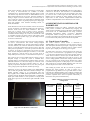
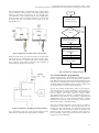
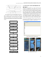
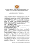
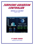
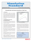
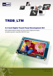
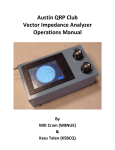
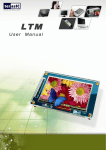
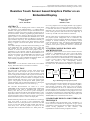
International Journal of Computer Applications (0975 – 8887)
International Conference on Information and Communication Technologies (ICICT- 2014)
Resistive Touch Sensor based Graphics Plotter on an
Embedded Display
Padma Prasada
Sukesh Rao M
E&C Dept.
MITE, Moodbidri
E&C Dept.
NMAMIT, Nitte
ABSTRACT
Today, many fields are adopting touch screens or touch panels
for applications with human/machinery or human/computer
interfaces. This paper presents the concepts and methods for the
interfacing of touch–screen sensor and TFT LCD Display unit to
host microcontroller. Software programming algorithm and their
implementation are also portrayed. Resistive touch sensor based
graphics plotter is one such hand held embedded device which
uses resistive touch panel and TFT LCD Display as an input and
output terminals respectively. The implementation methods give
special consideration to analog power–down strategies, efficient
analog to digital conversion and optimize the touch sensor
algorithm.
Active Matrix Display of Thin Film Transistor technology is used
as an output display unit, it’s being chosen since it is thin, flat
and consumes very less amount of power. The method and
workflow of resistive touch sensor based graphics plotter is
emphasized. In this approach LPC2103 microcontroller from
Philips Semiconductor Pvt Ltd, based on ARM7TDMI-S core is
used as host controller. The ARM7TDMI-S CPU features 8 A/D
channels, 32 general purpose I/O and several power saving
modes. Using Cross ware Embedded development Studio, the
entire software programming is done in C–language.
Keywords
ARM7TDMI – S Core, Resistive Touch Screen, active Matrix
display, Thin Film transistor, Touch Screen Controller.
1. INTRODUCTION
The paper aims in developing a resistive touch sensor based
graphics plotter, which accepts user input via resistive touch
panel and its being processed by host microcontroller. Touch
screens emerged from academics and corporate research labs in
the second half of the 1960s. One of the first places where they
gained some visibility was in the terminal of a computer–assisted
learning terminal that came out in 1972 as part of the PLATO
project. The popularity of smart phones, PDAs, portable game
consoles and many types of information appliances is driving the
demand for, and the acceptance of, touch screens [11].
The LPC2103 microcontrollers are based on a 32–bit
ARM7TDMI–S CPU with real time emulation that combines the
microcontroller with 32kb of embedded high speed flash
memory. Due their tiny size and low power consumption,
LPC2103 are ideal for applications where miniaturization is a key
requirement. Hence it is used as host controller in this project,
accepts input from resistive touch sensor, which is processed by
this host controller and, drives a TFT LCD display unit.
Modern industrial products in the current market are increasingly
using LCD panels to provide a more sophisticated visual
interface for the user. These panels have evolved into units that
are easy to work with, bright, have high contrast, and come in a
wide variety sizes. The most popular LCD panels are the
Amorphous Silicon Thin Film Transistor or a–SiTFT panels. We
use a TFT_320QVT TFT LCD display module to plot graphics,
which is drawn by user on resistive touch sensor using stylus. It
is controlled and driven by SSD1289 LCD controller driver.
SSD1289 is all in one TFT LCD driver that has integrated RAM,
power circuits, gate driver and source driver into single chip. It
can drive up to 262K color with resolution of 240x320.
The rest of this paper is organized as follows: section II describes
the proposed system configuration and its architecture and
functionality. Section III exposes hardware design and interface
technique. It includes interfacing of 4-wire Resistive Touch
screen and interfacing of TFT LCD display with ARM7TDMI-S
CPU. In section IV, software implementation method and
workflow of the system is portrayed. Section V concludes this
paper.
2. SYSTEM CONFIGURATION AND
ARCHITECHTURE
The proposed system consist a 4–wire resistive touch screen, host
controller i.e. ARM7TDMI–S CPU and a TFT LCD display
module. As user writes over touch screen, resistive touch screen
produces corresponding touch position dependent analog voltage.
Resistive touch screen is controlled and driven by ARM7TDMI–
S CPU; it receives analog voltage output from resistive touch
screen, and converts it into corresponding machine
understandable digital logic level to identify the touch point on
the touch screen. Its functional block diagram is represented in
Fig 1.
4 – Wire
Resistive
Touch
Screen
4 - Wire
interface
Host Controller
(Atmega 2560)
18 Bit
TFT LCD
Display
Module
Fig 1: Block diagram of proposed system
On the output side, host microcontroller drives TFT LCD display.
TFT LCD display is used to display the reproduced graphics,
which inputted via Resistive Touch screen. TFT LCD display
unit has integrated LCD driver IC SSD1289 from Solomon
Systech Limited. Once the touch point on resistive touch screen
has been identified, its coordinates are being mapped on to TFT
LCD display for displaying user interpreted graphics. Interfacing
technique for resistive touch screen and TFT LCD display with
ARM7TDMI-S CPU is discussed in next section
3. HARDWARE DESIGN AND INTERFACE
TECHNIQUE
In an embedded system development power consumption is a
critical issue to be considered. In our approach, we give special
consideration to analog power-down strategies like de-activating
unused on-chip peripherals of host controller, and
implementation of efficient analog to digital conversion.
37
International Journal of Computer Applications (0975 – 8887)
International Conference on Information and Communication Technologies (ICICT- 2014)
Touch screen controller is the key to this design. Currently there
are variety of microcontrollers are available in market.
Considering price, speed and flexibility and other factors, a high
cost-effective chip LPC2103 based on ARM7TDMI-S CPU of
Philips Semiconductors Pvt Ltd is used. LPC2103 includes an 8
analog to digital conversion channels with conversion time as
low as 2.44u Sec, which is key requirement to implement touch
screen controller, and also 32 general purpose input / output ports
along with, multiple serial interfaces including UARTs, I2C
buses, SPI and SSP.
Of all the kinds of touch screens available, resistive touch screens
are easy to interface, cost effective and they have fair sensitivity.
Resistive Touch screens are simple transducers. This touch
screen has a resistive layers in both X and Y directions.
According to the position of the touch, their X coordinate and Y
coordinate resistance changes. So, we have to measure the X and
Y coordinates resistance to get the position of the touch in terms
of X and Y coordinate position. Fig 2 gives the simple structure
of resistive Touch Screen.
To interface resistive Touch screen with a host microcontroller,
we need a microcontroller with inbuilt Analog-to-Digital
converter. ARM7TDMI-S CPU provides eight Analog-to-Digital
converter channels, out of this two channels are utilized for this
purpose. To read the position of the touch, we have to first read
touch position sequentially i.e. first read X position and then read
Y position. To do this, we connected X1 and Y2 pins of Touch
screen to ADC multiplexed GPIO pins of LP2103, i.e. P0.22 and
P0.23 respectively. And X2 and Y1 pins of Touch screen to
simple GPIO pins of LPC2103, i.e. P0.20 and P0.22 respectively.
TFT LCDs are class of Active Matrix displays, belong to type of
flat-panel display in which the screen is refreshed more
frequently than in conventional Passive Matrix display, and uses
individual transistors to control the charges on each cell in the
liquid-crystal layer. The silicon transistor matrix in a TFT is
typically composed of amorphous silicon (a-Si). They have good
color, good greyscale reproduction, and fast response [9].
Interfacing of TFT LCD display module with ARM7TDMI-S
CPU is done using Parallel 6800-series Interface technique. The
Parallel interface consists of 18 bi-directional data pins
D[17:0],𝑅/𝑊 , D/𝐶 , E and𝐶𝑆. 𝑅/𝑊 input HIGH indicates a read
operation from the Graphical Display Data Ram i.e. GDDRAM.
𝑅/𝑊 input LOW indicates a write operation to Display Data
RAM. The E input serves as data latch signal when 𝐶𝑆 is LOW
[6] [12].
The data lines DB0-DB7 and DB8-DB15 of TFT LCD module is
connected to P0.8-P0.15 and P0.24-P0.31 of ARM7TDMI-S
CPU respectively. Note that two bits are discarded, since 8-bits
per color are used. Control signal lines RS, WR, RD, CS and
RESET pins are interfaced to simple General purpose Input /
Output Ports of host controller. Implementation method and
workflow of implementation will be discussed in next section.
4. IMPLEMENTATION METHOD AND
WORKFLOW
Implementation consists two phases, controlling and reading
touch position coordinates and simultaneously mapping the
Touch position coordinates to TFT LCD display. Implementation
work carried out on ARM7TDMI-S CPU using Crossware
Embedded Development Studio. Crossware’s Embedded
Development Studio leverages the features of windows to
provide a development environment that allows the programmer
to concentrate on the primary task of software development.
4.1. Touch Screen Controller
The 4-Wire Resistive Touch Screen is interfaced to
ARM7TDMI-S CPU as explained in previous section. Used two
ADC multiplexed General Purpose Input / output pins for reading
X and Y Touch position coordinates and two simple General
Purpose input / Output pins for driving power signals.
As stated earlier, first have to read X position of the Touch, for
that, pin X1 of Touch Screen is programmed as Logic HIGH
(+3.3volts) and Configured X2 as logic LOW (ground). Resistive
Touch Screen contains a resistive layer in both directions. So,
when we apply Logic HIGH and Logic LOW to its pins, it will
create a voltage gradient in X direction. Voltage on the X channel
will vary according to the Touch position. Measure this voltage
to determine the X position. For this purpose, Y2 is connected to
ADC input and Y1 is kept at HIGH impedance state. The value
of ADC output will be relative value of the Touch.
After reading X position, now have to read the Y position to
determine the Touch position. To read Y position Y2 is
programmed as Logic HIGH, Y2 as Logic LOW, and X1 as ADC
input and X2 as HIGH impedance state. TABLE 1 illustrates the
4-wire resistive touch screen interfacing configuration. The entire
procedure explained above must be repeated continuously to
determine Touch position instantaneously.
TABLE 1 Resistive Touch Screen Interfacing
Configuration
ARM7TDMI-S
Port Pins
Resistive
Touch
Screen
Pins
Pin
Assignment
for X-Position
Pin
Assignment
for YPosition
P0.20
Y1
No
Connection
+3.3volts
P0.21
X2
Ground
No
Connection
P0.22
Y2
ADC Input
Ground
P0.23
X1
+3.3volts
ADC Input
Fig2: Four-wire Resistive Touch Screen
38
International Journal of Computer Applications (0975 – 8887)
International Conference on Information and Communication Technologies (ICICT- 2014)
The Pen Interrupt feature is implemented with a simple analog
circuit, schematic is shown in Figure 4. By simply pulling-up the
output pin of resistive Touch Screen to Vcc through series
connected diode, a basic interrupt function can be implemented.
While the Touch screen is untouched, the diode is not biased, and
no current will flow. The voltage level at point A will be
approximately Vcc.
START
Initialize all peripherals
like GPIO, ADC etc
TouchScreen_Config ();
N
Pen Interrupt
= LOW?
NO
YES
Create Voltage Gradient in X
direction and Connect Y2 as
ADC input
Tp_X=Read_X ();
Fig3: Configuration to read X and Y Touch position
Create Voltage Gradient in Y
direction and Connect X1 as
ADC input
Tp_Y=Read_Y ();
When the Touch screen is pressed, the diode is forward biased
and current flows to complete this current loop to ground. Now,
the voltage at point A is pulled LOW. The low going voltage
level at point A can be used as interrupt to host controller to
perform analog-to-digital conversion [13].
Determine the Touch Position
on the Touch Screen
Repeat
Fig5: Touch Screen reading work flow
4.2. TFT LCD Display programming
The term Liquid Crystal is used to describe a substance is a state
between liquid and solid, but which exhibits the properties of
both. Molecules in liquid crystals tend to arrange themselves until
they all point in the same specific direction. This arrangement of
molecules enables the medium to flow as a liquid. Liquid crystal
in a nematic phase, are used in LCD technology [9].
We use TFT_320QUT LCD Display module in this approach.
TFT LCD display uses a grid of transistors with the ability to
hold a charge for a limited period of time; only desired pixel
receives charge and hence improved image quality.
TFT_320QUT TFT LCD module is controlled and driven by
SSD1289 TFT controller driver. This module is interfaced with
ARM7TDMI-S CPU by using Parallel 6800-Series interface
technique as discussed in section III. Timing cycles for parallel
6800-series interface is illustrated in Fig 6.
Figure 4.Schematic for PENIRQ generating technique
Fig 5 describes the work flow of driving and reading resistive
touch Screen, to determine the Touch position coordinates.
Once host controller determines Touch position on Resistive
touch Screen, it will be taken as initial Touch position and, it’s
mapped on to TFT LCD Display. Next obtained Touch position
is compared with previous Touch position, to determine the
direction of user pen movement on Resistive Touch Screen. In
this way Resistive Touch screen touch position coordinates are
mapped on to TFT LCD display.
39
International Journal of Computer Applications (0975 – 8887)
International Conference on Information and Communication Technologies (ICICT- 2014)
5. VALIDATION AND EXPERIMENTAL
RESULTS
Fig6: Timing Waveform of Parallel 6800-Series Interface
There is sequence of operation to be performed to initialize the
TFT LCD. SSD1289 driver controller contains several command
registers. It’s necessary to write those register in sequence,
describing desired display mode, power setting, mode of interface
etc. Fig 7 gives the work flow of initialising of TFT LCD display
module.
The validation is performed in two steps; first touch screen
controller is implemented on target board using Crossware
Embedded Development Studio as explained in section IV. Its
response is being verified on windows hyper terminal connected
via two wire Rx and Tx ports of UART0 of the host controller.
Fig 8 shows the output values obtained on windows hyper
terminal for touch event as its co-ordinate values and untouch
event is represented by zeros. For the touch event the X and Y
coordinates are found as explained with the help of fig 5. First,
the voltage gradient is created for X axis and coordinate value is
converted using in-built ADC. Repeated same procedure for Y
axis coordinates estimation by creating voltage gradient to Yaxis. The obtained values are send to windows hyper terminal
through UART protocol and verified for various touch positions.
Fig 9 gives the implementation result for resistive touch sensor
based graphics plotter. The graphics is reproduced and displayed
on TFT LCD display as user writes over touch screen.
Power Supply setting
Display Control Setting
Set Oscillation Start Bit
Set Display ON Bit of
Command Register R07h
Exit from Sleep Mode by
Setting Sleep Mode Exit
Bit of R10h
Fig 8: Windows hyper terminal window
Wait for 30ms
Entry Mode Setting
LCD Driver and AC Setting
Write Data into Graphic
Display Data Ram
(GDDRAM)
Display ON
Fig 9: Implementation Result
Fig 7: LCD Power ON Sequence
40
International Journal of Computer Applications (0975 – 8887)
International Conference on Information and Communication Technologies (ICICT- 2014)
6. CONCLUSION
The 4-Wire Resistive Touch Screen interfacing with
ARM7TDMI-S CPU is designed, implemented and tested.
Windows hyper Terminal is being used for testing the
corresponding Touch coordinate values obtained as Touch
position on a Resistive Touch Screen. Measurements are made by
applying voltage gradient across one of the layer and measuring
the voltage on the other layer. This measurement is made twice,
once with the gradient across the ridged layer and the
measurement taken from the flexible layer and again with the
gradient applied to the flexible layer and the measurement taken
from the ridged layer.
The resistance of the bus bars and the connection circuitry
introduces an error (offset) in the voltage measurement. These
offsets can also drift, with changes in temperature, humidity and
time. So calibrating the screen periodically is to be done or can
utilize 8-wire Touch Screen. And non-linear response exists
when the contact between the two layers is not good. The
nonlinearity exists mainly when the level pressure is not enough.
In this paper we also present TFT LCD interfacing technique
with the ARM7TDMI-S CPU. Parallel 6800-Series Interfacing
technique is illustrated and implemented on host microcontroller.
Currently we are working on mapping of Touch position
coordinates onto the TFT LCD.
There is also an option to integrate a Micro SD card with this
system. With this enhanced feature user can display particular
image file or data file stored on Micro SD card, along with the
Touch input. A real-life equivalent of the system prototype
presented in this paper can be developed with minimal
development cost and relatively low operational cost.
7. REFERENCES
[1]
[2]
“Programming Techniques” issued June 1995 © Advanced
RISC Machines Ltd 1995
[3]
“ARM Architecture Reference Manual” issued 2005 ©
Advanced RISC Machines Ltd (ARM) 2005
[4]
“Touch Screen Control and Calibration -- Four-Wire,
Resistive”
Application
Note
By
CYPRESS
MICROSYSTEMs
[5]
“Resistive Touch screen Controller Using the S08 Family”
Application Note Freescale Semiconductor © Freescale
Semiconductor, 2010
[6]
“240 RGB x 320 TFT LCD Controller Driver integrated
Power Circuit, Gate and Source Driver with built-in RAM”
Copyright © 2007 Solomon Systech Limited
[7]
“Touch Panel Integration Guide” Newhaven Display
International, Inc.
[8]
“LPC2101/02/03 User Manual” Philips Semiconductors
[9]
“Fundamentals of Liquid Crystal Displays – How They
Work
and
What
They
Do”
FUJITSU
MICROELECTRONICS AMERICA, INC.
[10] “Practical
C Programming”. 3rd
Oualline, O'Reilly Media
Edition,
By Steve
[11] http://en.wikipedia.org/wiki/PLATO_%28computer_system
%29
[12] “SPI, Intel 8080, and Motorola 6800 communication
protocol between MCU and OLED driver”
Semiconductors, Application Note, May 2005
Opto
[13] “Touch Screen Controller Tips” Application Bulletin By
Skip Osgood, CK Ong, and Rick Downs © Burr-Brown
Corporation 2000
R.N. Aguilar, G.C.M. Meijer “Fast Interface Electronics for
a Resistive Touch-Screen” IEEE J 2000
41