1
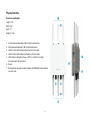
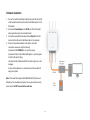
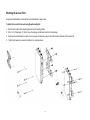
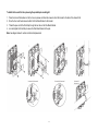
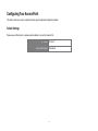
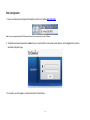
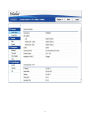
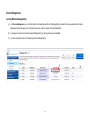
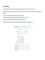
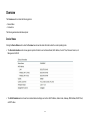
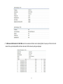
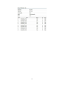
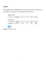
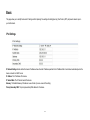
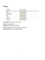
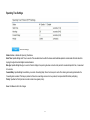
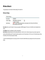
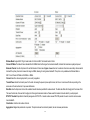
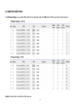
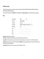
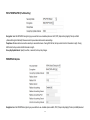
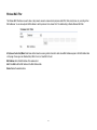
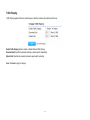
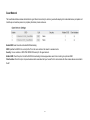
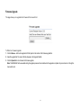
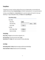
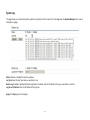
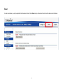
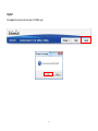
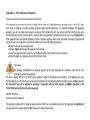
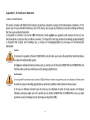
1 Table of Contents Chapter 1............................................................................................................................................................................................................................. 5 Key Features ............................................................................................................................................................................................................... 7 System Requirements ................................................................................................................................................................................................. 8 Package Contents ....................................................................................................................................................................................................... 9 Applications ............................................................................................................................................................................................................... 10 Technical Specifications .............................................................................................................................................................................................11 Physical Interface ...................................................................................................................................................................................................... 13 Chapter 2........................................................................................................................................................................................................................... 14 Considerations for Wireless Installation ..................................................................................................................................................................... 15 AP Setup ................................................................................................................................................................................................................... 25 Computer Settings ..................................................................................................................................................................................................... 25 Hardware Installation ................................................................................................................................................................................................. 29 Mounting the Access Point ........................................................................................................................................................................................ 30 Chapter 3........................................................................................................................................................................................................................... 32 Default Settings ......................................................................................................................................................................................................... 33 Web Configuration ..................................................................................................................................................................................................... 34 Device Management.................................................................................................................................................................................................. 36 Chapter 4........................................................................................................................................................................................................................... 43 Device Status ............................................................................................................................................................................................................ 44 Connections .............................................................................................................................................................................................................. 47 Chapter 5........................................................................................................................................................................................................................... 48 IPv4 Settings ............................................................................................................................................................................................................. 49 IPv6 Settings ............................................................................................................................................................................................................. 50 Spanning Tree Settings ............................................................................................................................................................................................. 51 2 Chapter 6........................................................................................................................................................................................................................... 52 Wireless Settings ....................................................................................................................................................................................................... 53 2.4 GHz/5 GHz SSID Profile ...................................................................................................................................................................................... 56 Wireless Security ....................................................................................................................................................................................................... 58 Wireless MAC Filter ................................................................................................................................................................................................... 61 Traffic Shaping........................................................................................................................................................................................................... 62 Guest Network ........................................................................................................................................................................................................... 63 Fast Handover ........................................................................................................................................................................................................... 65 Management VLAN Settings ..................................................................................................................................................................................... 66 Chapter 7........................................................................................................................................................................................................................... 67 SNMP Settings .......................................................................................................................................................................................................... 68 CLI/SSH Settings....................................................................................................................................................................................................... 70 HTTPS Settings ......................................................................................................................................................................................................... 71 Email Alerts ............................................................................................................................................................................................................... 72 Date and Time Settings ............................................................................................................................................................................................. 73 Wi-Fi Scheduler ......................................................................................................................................................................................................... 74 Tools .......................................................................................................................................................................................................................... 76 .................................................................................................................................................................................................................................. 79 Device Discovery ....................................................................................................................................................................................................... 80 Chapter 8........................................................................................................................................................................................................................... 81 Account Settings........................................................................................................................................................................................................ 82 Firmware Upgrade ..................................................................................................................................................................................................... 83 Backup/Restore ......................................................................................................................................................................................................... 84 System Log ............................................................................................................................................................................................................... 85 Reset ......................................................................................................................................................................................................................... 86 Logout ....................................................................................................................................................................................................................... 87 Glossary ............................................................................................................................................................................................................................ 88 3 Appendix ........................................................................................................................................................................................................................... 97 Appendix A - FCC Interference Statement ................................................................................................................................................................. 98 Appendix B - IC Interference Statement .................................................................................................................................................................... 99 Appendix C - CE Interference Statement ................................................................................................................................................................ 101 4 Chapter 1 Product Overview 5 Introduction The EWS860AP is a high-powered, long-range 3x3 Dual-Band Wireless 802.11ac/a/b/g/n Outdoor Access Point with speeds up to 450 Mbps on 2.4 GHz and 1300 Mbps on 5 GHz band. This Access Point is designed to operate in a variety of outdoor environments. Its high-powered, long-range characteristics make it a cost-effective alternative to ordinary Access Points that don’t have the range and reach to connect to a growing number of wireless users who wish to connect to a business network. The EWS860AP supports 2.4 GHz frequency band under 802.11 b/g/n mode while at the same time provides 5 GHz band under 802.11ac/a/n mode for communicating to and from 5 GHz capable computers, tablets or smart phones or for transferring files. Several EWS860APs can be deployed in a campus setting using the 5 GHz band as a backhaul to provide multiple 2.4 GHz wireless cells for computers or mobile devices in common outdoor areas. The EWS860AP is easy to install in virtually any location with its included PoE (Power over Ethernet) injector for quick outdoor installation. The EWS860AP enables network administrators to control its transmit power and feature settings for selecting narrow bandwidth and traffic shaping. The EWS860AP also supports wireless encryption including Wi-Fi Protected Access (WPA-PSK/WPA2-PSK) Encryption, and IEEE 802.1x with RADIUS. Maximum data rates are based on IEEE 802.11 standards. Actual throughput and range may vary depending on many factors including environmental conditions, distance between devices, radio interference in the operating environment, and mix of devices in the network. Features and specifications are subjected to change without prior notice. Trademarks and registered trademarks are the property of their respective owners. For United States of America: Copyright © 2014 EnGenius Technologies, Inc. All rights reserved. 6 Key Features Deploy and manage with ease using EWS Series WLAN Management Controller Switches IP68-rated ruggedized enclosure for harsh outdoor environments Up to 29 dBm transmit power enabling long range connectivity Supports IEEE802.11ac/a/b/g/n wireless standards with up to 450 Mbps data rate on 2.4 GHz band and 1300 Mbps on 5 GHz band Three detachable 5 dBi 2.4 GHz Omni-directional antennas Three detachable 7 dBi 5 GHz Omni-directional antennas Backwards compatible with IEEE802.11a/b/g/n wireless devices Integrated Power over Ethernet (IEEE802.3at) for lowering deployment costs. Can be powered using either the included power adapter or via PoE with PoE 802.3at capable Switches or Injectors Dual Band/Three Stream Band Steering to load balance clients between 2.4 GHz and 5 GHz for better throughput performance1 Secured Guest Network option available 7 System Requirements The following are the Minimum System Requirements in order to configure the device: Computer with an Ethernet interface or wireless network capability Windows OS (XP, Vista, 7, 8), Mac OS, or Linux-based operating systems Web-Browsing Application (i.e.: Internet Explorer, Firefox, Chrome, Safari, or another similar browser application) 8 Package Contents The package contains the following items (all items must be in package to issue a refund): EWS860AP Access Point 3 detachable 5 dBi 2.4 GHz Omni-directional Antennas 3 detachable 7 dBi 5 GHz Omni-directional Antennas Power Adapter (48V/0.8A) PoE Injector (EPE-48GR) Grounding Cable Pole Mount Bracket Wall Mount Base Mounting Screw Set Quick Installation Guide 9 Applications Wireless LAN (WLAN) products are easy to install and highly efficient. The following list describes some of the many applications made possible through the power and flexibility of WLANs: Difficult-to-Wire Environments: There are many situations where wires cannot be installed, deployed easily, or cannot be hidden from view. Older buildings, sites with multiple buildings, and/or areas that make the installation of a Ethernet-based LAN impossible, impractical or expensive are sites where WLAN can be a network solution. Temporary Workgroups: Create temporary workgroups/networks in more open areas within a building; auditoriums, amphitheaters classrooms, ballrooms, arenas, exhibition centers, or temporary offices where one wants either a permanent or temporary Wireless LAN established. The Ability to Access Real-Time Information: Doctors/Nurses, Point-of-Sale Employees, and/or Warehouse Workers can access real-time information while dealing with patients, serving customers, and/or processing information. Frequently Changing Environments: Set up networks in environments that change frequently (i.e.: Show Rooms, Exhibits, etc.). Small Office and Home Office (SOHO) Networks: SOHO users require a cost-effective, easy, and quick installation of a small network. Training/Educational Facilities: Training sites at corporations or students at universities use wireless connectivity to exchange information between peers and easily access information for learning purposes. 10 Technical Specifications Management: Auto Channel Selection Multiple SSID: 16 SSIDs (8 SSIDs per Radio) BSSID SNMP V1/V2c/V3 MIB I/II, Private MIB Standard: IEEE802.11ac/a/n on 5 GHz IEEE802.11b/g/n on 2.4 GHz IEEE802.3at VLAN Tag/VLAN Pass-through Clients Statistics Save Configuration as User Default Fast Roaming E-Mail Alert RADIUS Accounting Guest Network Antenna: 6 External N-type Antennas 3 x Detachable 5 dBi 2.4 GHz Omni-directional Antennas 3 x Detachable 7 dBi 5 GHz Omni-directional Antennas Physical Interface: 2 x 10/100/1000 Gigabit Ethernet Port with PoE support Control CLI Supported Distance Control (ACK Timeout) Multicast Supported Auto Reboot Obey Regulatory Power LAN1 Port: IEEE802.3at PoE Input LAN2 Port: IEEE802.3af PoE Output Both Ethernet Ports support Surge Protection to 6KV LED Indicators: Power LAN 1 Security: LAN 2 2.4 GHz 5 GHz WEP Encryption - 64/128/152 bit WPA/WPA2 Personal (WPA-PSK using TKIP or AES) WPA/WPA2 Enterprise (WPA-PSK using TKIP or AES) Hides SSID in beacons MAC address filtering, up to 50 MACs Wireless STA (Client) connection list Power Requirements: External Power Adapter, DC IN, 48V/0.8A IEEE802.3at support 11 Https Support SSH Support QoS (Quality of Service): Complaint with IEEE 802.11e standard Physical/Environment Conditions: Operating: Temperature: -4 °F~158 °F (-20 °C~70 °C) Humidity (non-condensing): 90% or less Storage: Temperature: -22 °F~176 °F (-30 °C~80 °C) Humidity (non-condensing): 90% or less 12 Physical Interface Dimensions and Weights Length: 11.22” Width: 8.58” Depth: 2.1” Weight: 4.17 lbs 1. 2. 3. 4. 5. 2.4 GHz Antennas: Detachable 5 dBi 2.4 GHz Omni-directional 5 GHz Antennas Detachable 7 dBi 5 GHz Omni-directional LAN Port 1 (802.3at PoE Input): Ethernet port for RJ-45 cable. LAN Port 2 (802.3af PoE Output): Ethernet port for RJ-45 cable. LED Indicators: LED lights for Power, LAN Port 1, LAN Port 2, 2.4 GHz Connection and 5 GHz Connection. 6. Ground 7. Mounting Holes: Using the provided hardware, the EWS860AP can be attached to a wall or pole. 13 Chapter 2 Connections 14 Before You Begin This section will guide you through the installation process. Placement of the EnGenius Access Point is essential to maximize the Access Point’s performance. Considerations for Wireless Installation The operating distance of all wireless devices can often not be pre -determined due to a number of unknown obstacles in the environment in which the device is deployed. The following list describes the solutions that the EWS860AP offers as a flexible, robust and powerful Outdoor Access Point or Bridge: • Difficult-to-Wire Environments - In outdoor environments sometimes extending a network by laying Ethernet or fiber cabling is either cost prohibitive or physically not possible. The EWS860AP, enables the extension of an existing company network via the propagation of a wireless signal rather than cable as a much m ore cost-effective alternative. • Temporary Workgroups – Creating a wired network infrastructure for a temporary outdoor worksite/workgroup or special event venue may not be a cost - or time-efficient solution and may present deployment issues if trenches for cabling cannot be dug in existing landscaping. The EWS860AP enables companies, in a matter of minutes, to create an outdoor wireless network that can provide Internet access (based on an existing broadband connection) or access to the company’s networked resources like printers, hard drives and databases. • Wireless Extensions of Ethernet Networks – The range of a wired network is typically limited within the confines of a single building. In situations where there are multiple buildings on a campus or another company building very remot e from the main building then a Wireless Access Point or Bridge deployment using the EWS860AP provides a very cost-effective way to cover large outdoor areas around a company office or even conne ct to other company buildings. • Expanding User Capacity and Connectivity To Additional Devices – The EWS860AP is designed specifically to extend and expand existing company networks. Its high 15 transmit power capability and enhanced receive sensitivity results in the ability for a company to connect to more employees, company guests or other wireless clients. The EWS860AP’s additional 5GHz frequency radio can be act as a separate AP or bridge to either provide 5GHz wireless access to 5GHz clien ts; Or connect to other 5GHz devices to provide backhaul service. • Redundancy – In situations where a portion of an existing wired network may fail, the EWS860AP offers a measure of stability and redundancy to other employees can continue to communicate with one another or access mission critical databases. 16 Compatibility Your EWS860AP supports the following Neutron Series EWS Switch models*: EWS5912FP 8-Port Layer 2 PoE+ Wireless Management Switch with 2 SFP Supports up to 20 Neutron Series Access Points EWS7928P 24-Port Layer 2 PoE+ Wireless Management Switch with 4 SFP Supports up to 50 Neutron Series Access Points EWS7928FP 24-Port Layer 2 PoE+ Wireless Management Switch with 4 SFP Supports up to 50 Neutron Series Access Points EWS7952FP 48-Port Layer 2 PoE+ Wireless Management Switch with 4 SFP Supports up to 50 Neutron Series Access Points *Future firmware releases will support additional models. 17 Connecting to the Neutron Series Controller Switch The EWS860AP can operate as a stand-alone AP connecting to third-party PoE capable switches, but more control and versatile management of the AP can be achieved when it is connected to an EnGenius Neutron Series Controller Switch. The following section will guide you in connecting your EWS Controller Switch as well as a brief overview of the management options available for your network: A) Connect the supplied Power Cord to the EWS Switch and plug the other end into an electrical outlet. Verify the Power LED indicator is lit on the EWS Switch. Wait for the EWS Controller Switch to complete boot up. It might take few minutes to complete the process. B) Connect one end of a Category 5/6 Ethernet cable into the Gigabit (10/100/1000) Ethernet port on the Switch’s front panel and the other end to the Ethernet Port on the computer. Verify that the LED on the Ethernet port of the Switch is green. C) Connect the EWS860AP to the EWS Controller Switch. Verify that the LED on the Ethernet port(s) of the EWS Switch is green. 18 IP Address Configuration Windows XP, 7, 8 A) Once your computer is on, ensure that your TCP/IP is set to On or Enabled. Open Network Connections and then click Local Area Connection. Select Internet Protocol Version 4 (TCP/IPv4). 19 B) If your computer is already on a network, ensure that you have set it to a Static IP Address on the interface. Please fill in the IP address, Subnet Mask, and Default Gateway you would like to use based on how you utilizing the Access Point. The Access Point can be setup to be managed in groups via an EWS Switch or in Standalone mode: Managed: 192.168.0.239 Standalone: 192.168.1.XX 20 21 Apple Mac OS X A) Go to System Preferences (it can be opened in the Applications folder or by electing it in the Apple Menu). B) Select Network in the Internet & Network section. C) Highlight Ethernet. D) In Configure IPv4, select Manually. 22 E) Enter an IP address that is different from the AP and Subnet mask, then click OK. Note: Ensure that the IP address and Subnet mask are on the same subnet as the device. For example: EWS860AP IP address: 192.168.1.1 PC IP address: 192.168.1.2 – 192.168.1.255 PC Subnet mask: 255.255.255.0 F) Click Apply when finished. 23 WLAN Management Controller Switch Setup A) Open a web browser on your computer. In the address bar of the web browser, enter 192.168.0.239 and press Enter. B) A login screen will appear. By default, username is admin and the password is password. Enter the current username and password of the WLAN Management Controller Switch and then click Login. C) The EnGenius WLAN Management Controller Switch User Interface will appear. Make sure the Controller State is set to Enabled. You will now be able to add EWS APs to the Switch to configure and manage from one central location. 24 Standalone AP Setup Computer Settings Windows XP/Windows 7 In order to use the Access Point, you must first configure the TCP/IPv4 connection of your Windows OS computer system. 1. Click the Start button and open the Control Panel. Windows XP Windows 7 2a. In Windows XP, click on Network Connections. 25 2b. In Windows 7, click View network status and tasks in the Network and Internet section, then select Change adapter settings. 3. Right click on Local Area Connection and select Properties. 4. Select Internet Protocol Version 4 (TCP/IPv4) and then select Properties. 26 5. Select Use the following IP address and enter an IP address that is different from the Access Point and Subnet mask, then click OK. Note: Ensure that the IP address and Subnet mask are on the same subnet as the device. For example: Access Point IP address: 192.168.1.1 PC IP address: 192.168.1.2 – 192.168.1.255 PC Subnet mask: 255.255.255.0 27 Apple Mac OS X 1. Go to System Preferences (it can be opened in the Applications folder or by selecting it in the Apple Menu). 2. Select Network in the Internet & Network section. 3. Highlight Ethernet. 4. In Configure IPv4, select Manually. 5. Enter an IP address that is different from the Access Point and Subnet mask, then click OK. Note: Ensure that the IP address and Subnet mask are on the same subnet as the device. For example: Access Point IP address: 192.168.1.1 PC IP address: 192.168.1.2 – 192.168.1.255 PC Subnet mask: 255.255.255.0 6. Click Apply when finished. 28 Hardware Installation 1. Connect one end of the Ethernet cable into the main LAN port (PoE) of the Access Point and the other end to the AP Ethernet port on the PoE injector. 2. Connect the Power Adapter to the DC-IN port of the PoE injector and plug the other end in to an electrical outlet. 3. Connect the second Ethernet cable into the LAN port of the PoE injector and the other end to the Ethernet port on the computer. 4. Screw on the provided antennas to the device. Once both connections are secure, verify the following: a) Ensure that the POWER light is on (it will be green). b) Ensure that the 2.4 GHz/5 GHz WLAN light is on (it will be green for both 5 GHz and 2.4 GHz). c) Ensure that the LAN (Computer/AP Connection) light is on (it will be green). d) Once all three lights are on, proceed to set up the Access Point using the computer. Note: The Access Point supports both IEEE 802.3at PoE (Power over Ethernet) or the included power injector. You may use either one as the power source. Do NOT use both at the same time. 29 Mounting the Access Point Using the provided hardware, the Access Point can be attached to a ceiling or wall. To attach the Access Point to a wall using the wall mounting kit: 1. Mark the four locations of the mounting holes on the flat mounting surface. 2. Drill a 1.46” (37mm) deep .31” (8 mm) hole in the markings and hammer the bolts into the openings. 3. Place the lock and flat washers on the four hex cap screws and drive the screws to attach the bracket to the back of the Access Point. 4. Tighten the flat washers to secure the bracket to the mounting surface. 30 To attach the Access Point to a pole using the provided pole mounting kit: 1. Place the lock and flat washers on the four hex cap screws and drive the screws to attach the bracket to the back of the Access Point. 2. Drive the four round head screws to attach the Pole Mount Bracket to the bracket. 3. Thread the open end of the Pole Strap through the two tabs on the Pole Mount Bracket. 4. Lock and tighten the Pole Strap to secure the Pole Mount Bracket to the pole. Note: See diagram below for vertical and horizontal placements. . 31 Chapter 3 Configuring Your Access Point 32 Configuring Your Access Point This section will show you how to configure the device using the web-based configuration interface. Default Settings Please use your Ethernet port or wireless network adapter to connect the Access Point. IP Address 192.168.1.1 Username/Password admin/admin 33 Web Configuration 1. Open a web browser (Internet Explorer/Firefox/Safari) and enter the IP Address http://192.168.1.1. Note: If you have changed the default LAN IP Address of the Access Point, ensure you enter the correct IP Address. 2. The default username and password are: admin. Once you have entered the correct username and password, click the Login button to open the web-based configuration page. 3. If successful, you will be logged in and see the Access Point User Interface. 34 35 Device Management Locating Wireless Managed AP(s) A) Go to Device Management on your Controller Switch UI and select Access Points. All Managed AP(s) connected to the same network as the Wireless Management Switch will appear on the right side of the screen, under the Access Point AP(s) Detected list. B) To manage the Access Points, select the desired Managed AP(s) by checking the boxes and click Add. C) You will be prompted to enter an IP Address range for the Managed AP(s). 36 General Settings A) Enter the Device Name for the Access Point so that you can differentiate between devices if you plan to use more than one AP. B) Enter the Administrator account username and password to create an account that can access all features of the AP. next, enter the password again for verification. C) Select DHCP or Static to determine how IP addresses will be assigned for the AP: - Select DHCP for an IP Address to be assigned automatically if there is a DHCP server in the network. - Select Static to enter the IP Address, Subnet Mask, Gateway, and DNS Server manually. Please refer to the General Settings section on your Switch’s User Manual for more information. Click Apply to continue. 37 Wireless Radio Settings After configuring the General Settings page, you will need to configure the Wireless Radio Settings. Enter information pertaining to each frequency band that applies to your AP. Once finished, click Apply to continue. 38 WLAN Settings 2.4/5 GHz Next, you will need to configure the WLAN settings for each band. Click on an SSID to access Basic, Traffic, Fast Roaming, and Security settings. Once finished, click Save to apply the settings to the SSID. Once you have applied your configurations for each SSID, click Apply to continue. 39 Advanced Settings Next, you will need to configure the Advanced Settings for the Access Point. Once finished, click Apply to continue. Band Steering: The Band Steering feature detects Dual Band clients and shifts them to the 5 GHz band to relieve network congestion on the 2.4 GHz band to maintain optimal data traffic flow, helping clients on both bands. Fast Handover: With Fast Handover enabled, the EWS860AP will send a disassociation request to the wireless client and let it find another AP to handover and associate upon detecting the wireless client’s RSSI value as lower than specified. The range is from -90dBm~-60dBm. 40 Guest Network: A Guest Network is a section of a computer network designed for use by temporary visitors. This subnetwork often provides full Internet connectivity, but also strictly limits access to any internal web sites or files. Wireless Security: The Wireless Security section lets you configure the EWS860AP’s security modes: WEP, WPA-PSK, WPA2-PSK, WPA-PSK Mixed, WPA-Enterprise, WPA2-Enterprise and WPA Mixed Enterprise. It is strongly recommended that you use WPA2-PSK for the most secure connection. 41 Managing A WLAN Management Controller Switch For further Switch configurations, click on Switch at the top left of the dashboard. Refer to your Switch’s User Manual for more information on these configuration settings. 42 Chapter 4 Overview 43 Overview The Overview section contains the following options: • Device Status • Connections The following sections describe these options: Device Status Clicking the Device Status section under the Overview menu shows the status information about the current operating mode. The Device Information section shows general system information such as Device Name, MAC address, Current Time, Firmware Version, and Management VLAN ID The LAN Information section shows the Local Area Network settings such as the LAN IP Address, Subnet mask, Gateway, DNS Address, DHCP Client, and STP status. 44 The Wirelesss LAN Information 2.4 GHz/5 GHz section shows wireless information such as Operating Mode, Frequency, and Channel. Since the Access Point supports multiple-SSIDs, information about each SSID and security settings are displayed. 45 46 Connections Clicking the Connections section under the Device Status menu displays the list of clients associated to the Access Point’s 2.4 GHz/5 GHz bands, along with the MAC address, TX, RX and signal strength for each client. Clicking Kick in the Block column removes this client. Click Refresh to refresh the Connection List page. 47 Chapter 5 Network 48 Basic This page allows you to modify the device’s IP settings and the Spanning Tree settings. Enabling Spanning Tree Protocol (STP) will prevent network loops in your LAN network. IPv4 Settings IP Network Settings: Select whether the device IP address will use the static IP address specified in the IP Address field or be obtained automatically when the device connects to a DHCP server. IP Address: The IP Address of this device. IP Subnet Mask: The IP Subnet mask of this device. Gateway: The Default Gateway of this device. Leave it blank if you are unsure of this setting. Primary/Secondary DNS: The primary/secondary DNS address for this device. 49 IPv6 Settings Link-Local Address: Check this if you want to use a Link-Local Address. IP Address: The IPv6 IP Address of this device. Subnet Prefix Length: The IPv6 Subnet Prefix Length of this device. Gateway: The IPv6 Default Gateway of this device. Leave it blank if you are unsure of this setting. Primary / Secondary DNS: The primary / secondary DNS address for this device. 50 Spanning Tree Settings Status: Enables or disables the Spanning Tree feature. Hello Time: Specifies Bridge Hello Time, in seconds. This value determines how often the device sends handshake packets to communicate information about the topology throughout the entire Bridged Local Area Network. Max Age: Specifies Bridge Max Age, in seconds. If another bridge in the spanning tree does not send a hello packet for an extended period of time, it is assumed to be inactive. Forward Delay: Specifies Bridge Forward Delay, in seconds. Forwarding Delay Time is the time spent in each of the Listening and Learning states before the Forwarding state is entered. This delay is provided so that when a new bridge comes onto a busy network, it analyzes data traffic before participating. Priority: Specifies the Priority Number. A smaller number has a greater priority. Save: Click Save to confirm the changes. 51 Chapter 6 2.4 GHz & 5 GHz Wireless 52 Wireless Network This page displays the current status of the Wireless settings of the Access Point. Wireless Settings Device Name: Enter a name for the device. The name you type appears in SNMP management. This name is not the SSID and is not broadcasted to other devices. Country/Region: Select a Country/Region to conform to local regulations. Band Steering: Enable Band Steering to shift Dual Band-capable clients to 5 GHz from the 2.4 GHz band, helping to relieve network congestion and maintain optimal data traffic speeds. This means that sensitive applications such as IP camera streams, VoIP (Voice over IP), HD video streaming and large file transfers perform with improved quality and reliability. *In order for the Band Steering feature to work properly, both the 2.4 GHz and the 5 GHz SSID and security settings must be under the same selection settings. 53 Wireless Mode: Supports 802.11b/g/n mixed mode in 2.4 GHz and 802.11a/n mixed mode in 5 GHz. Channel HT Mode: The default channel bandwidth is 20/40MHz. Note that the larger the channel bandwidth, the better the transmission quality and speed. Extension Channel: Use the drop-down list to set the Extension Channel as an Upper or Lower channel. An extension channel is a secondary channel used to bond with the primary channel to increase this range to 40MHz, allowing for much greater bandwidth. This option is only available when Wireless Mode is 802.11n and Channel HT Mode is 20/40 MHz or 40MHz. Channel: Select the channel appropriate for your country’s regulation. Transmit Power: Select the transmit power for the radio. Increasing the power improves performance, but if two or more Access Points are operating in the same area on the same channel, it may cause interference. Data Rate: Use the drop-down list to set the available transmit data rates permitted for wireless clients. The data rate affects the throughput of the Access Point. The lower the data rate, the lower the throughput, but the longer transmission distance. Please select the balance that works best for your deployment. RTS/CTS Threshold: Specifies the threshold package size for RTC/CTS. A smaller number causes RTS/CTS packets to be sent more often and consumes more bandwidth. Client Limits: Limits the total number of clients. Aggregation: Merges data packets into one packet. This option reduces the number of packets, but also increases packet sizes. 54 AP Detection: AP Detection can select the best channel to use by scanning nearby areas for Access Points. Distance: Specifies the distance between the Access Point and its clients. Note that longer distances may drop higher speed connections. 55 2.4 GHz/5 GHz SSID Profile Under Wireless Settings, you can edit the SSID profile to fit your deployment needs. Click Edit under the SSID you would like to make changes to. Enable: Check this option to enable this profile for client use. 56 SSID: Specifies the SSID for the current profile. Security: Displays the Security Mode the SSID uses. You can click Edit to change the security mode. For more details, see the next section. Hidden SSID: Check this option to hide the SSID from clients. If checked, the SSID will not appear in the site survey. Client Isolation: Check this option to prevent communication between client devices. VLAN Isolation: Check this option to enable the VLAN Isolation feature. VLAN ID: Specifies the VLAN ID for the SSID profile. 57 Wireless Security The Wireless Security section lets you configure the Access Point’s security modes: WEP, WPA-PSK, WPA2-PSK, WPA-PSK Mixed, WPA-Enterprise, WPA2-Enterprise and WPA Mixed Enterprise. It is strongly recommended that you use WPA2-PSK. Click on the Edit button under Wireless Settings next to the SSID to change the security settings. WEP Auth Type: Select Open System or Shared Key. Input Type: ASCII: Regular Text (Recommended) or HEX: Hexadecimal Numbers (For advanced users). Key Length: Select the desired option and ensure the wireless clients use the same setting. Your choices are: 64, 128, and 152-bit password lengths. Default Key: Select the key you wish to be default. Transmitted data is ALWAYS encrypted using the Default Key; the other Keys are for decryption only. You must enter a Key Value for the Default Key. Encryption Key: Enter the Key Value or values you wish to use. The default is option is None. 58 WPA-PSK/WPA2-PSK (Pre-Shared Key) Encryption: Select the WPA/WPA2 encryption type you would like to use. Available options are: Both, TKIP (Temporal Key Integrity Protocol) and AES (Advanced Encryption Standard). Please ensure that your wireless clients use the same settings. Passphrase: Wireless clients must use the same Key to associate the device. If using ASCII format, the Key must be from 8~63 characters in length. If using HEX format, the Key must be 64 HEX characters in length. Group Key Update Interval: Specify how often, in seconds, the Group Key changes. WPA/WPA2-Enterprise Encryption: Select the WPA/WPA2 encryption type you would like to use. Available options are Both, TKIP (Temporal Key Integrity Protocol) and AES(Advanced 59 Encryption Standard). Please ensure that your wireless clients use the same settings. Group Key Update Interval: Specify how often, in seconds, the group key changes. Radius Server: Enter the IP address of the Radius server. Radius Port: Enter the port number used for connections to the Radius server. Radius Secret: Enter the secret required to connect to the Radius server. Radius Accounting: Enables or disables the accounting feature. Radius Accounting Server: Enter the IP address of the Radius accounting server. Radius Accounting Port: Enter the port number used for connections to the Radius accounting server. Radius Accounting Secret: Enter the secret required to connect to the Radius accounting server. Interim Accounting Interval: Specify how often, in seconds, the accounting data sends. Note: 802.11n does not allow WEP/WPA-PSK TKIP/WPA2-PSK TKIP security modes. The connection mode will automatically change from 802.11n to 802.11g. Please be aware of this when making your selections. 60 Wireless MAC Filter The Wireless MAC Filter feature is used to allow or deny network access to wireless clients (computers, tablet PCs, NAS, smart phones, etc.) according to their MAC addresses. You can manually add a MAC address to restrict permission to the Access Point. The default setting is: Disable Wireless MAC Filter. ACL (Access Control List) Mode: Determines whether network access is granted or denied to clients whose MAC addresses appear in the MAC address table on this page. Choices given are: Disabled, Deny MAC in the list, or Allow MAC in the list. MAC Address: Enter the MAC address of the wireless client. Add: Click Add to add the MAC address to the MAC Address table. Delete: Deletes the selected entries. 61 Traffic Shaping Traffic Shaping regulates the flow of packets leaving an interface to deliver improved Quality of Service. Enable Traffic Shaping: Select to enable or disable Wireless Traffic Shaping. Download Limit: Specifies the wireless transmission speed used for downloading. Upload Limit: Specifies the wireless transmission speed used for uploading. Save: Click Save to apply the changes. 62 Guest Network The Guest Network feature allows administrators to grant Internet connectivity to visitors or guests while keeping other networked devices (computers and hard drives) and sensitive personal or proprietary information private and secure. Enable SSID: Select to enable or disable SSID broadcasting. SSID: Specifies the SSID for the current profile. This is the name visible on the network to wireless clients. Security: You can use None or WPA-PSK / WPA2-PSK security for this guest network. Hidden SSID: Check this option to hide the SSID from broadcasting to discourage wireless users from connecting to a particular SSID. Client Isolation: Check this option to prevent wireless clients associated with your Access Point to communicate with other wireless devices connected to the AP. 63 After enabling the Guest Network in the SSID Config page, assign an IP Address, Subnet Mask and DHCP server IP address range for this Guest Network. Manual IP Settings IP Address: Specify an IP Address for the Guest Network. Subnet Mask: Specify the Subnet Mask IP Address for the Guest Network. Automatic DHCP Server Settings Starting IP Address: Specify the starting IP Address range for the Guest Network. Ending IP Address: Specify the ending IP Address range for the Guest Network. WINS Server IP: Specify the WINS Server IP Address for the Guest Network. WINS stands for Windows Internet Name Service. It is Microsoft's implementation of their NetBIOS Name Service (NBNS), a name server and service for NetBIOS computer names. 64 Fast Handover With Fast Handover enabled, the AP will send a disassociation request to the wireless client and let it find another AP to handover and associate upon detecting the wireless client’s RSSI value as lower than specified. The RSSI value can be adjusted to allow more clients to stay associated to this AP. Note that setting the RSSI value too low may cause wireless clients to reconnect frequently. 65 Management VLAN Settings This section allows you to assign a VLAN tag to packets. A VLAN is a group of computers on a network whose software has been configured so that they behave as if they were on a separate Local Area Network (LAN). Computers on VLAN do not have to be physically located next to one another on the LAN. Status: If your network includes VLANs and if tagged packets need to pass through the Access Point, select Enable and enter the VLAN ID. Otherwise, click Disable. Save: Click Save to apply the changes. Note: If you reconfigure the Management VLAN ID, you may lose your connection to the Access Point. Verify that the DHCP server supports the reconfigured VLAN ID and then reconnect to the Access Point using the new IP address. 66 Chapter 7 Management 67 SNMP Settings This page allows you to assign the Contact Details, Location, Community Name, and Trap Settings for Simple Network Management Protocol (SNMP). This is a networking management protocol used to monitor network attached devices. SNMP allows messages (called protocol data units) to be sent to various parts of the network. Upon receiving these messages, SNMP compatible devices (called agents) returns the data stored in their Management Information Bases. To configure SNMP Settings, click under the Advanced tab on the side bar under Management. Status: Enables or Disables the SNMP feature. Contact: Specifies the contact details of the device. Location: Specifies the location of the device. 68 Port: Displays the port number. Community Name (Read Only): Specifies the password for the SNMP community for read only access. Community Name (Read/Write): Specifies the password for the SNMP community with read/write access. Trap Destination Address: Specifies the port and IP address of the computer that will receive the SNMP traps. Trap Destination Community Name: Specifies the password for the SNMP trap community. SNMPv3 Status: Enables or disables the SNMPv3 feature. User Name: Specifies the username for the SNMPv3.feature Auth Protocol: Select the Authentication Protocol type: MDS or SHA. Auth Key: Specify the Authentication Key for authentication. Priv Protocol: Select the Privacy Protocol type: DES. Priv Key: Specifies the privacy key for privacy. Engine ID: Specifies the Engine ID for SNMPv3. 69 CLI/SSH Settings Most users will configure the device through the graphical user interface (GUI). However, for those who prefer an alternative method there is the Command Line Interface (CLI). The CLI can be accessed through a command console, modem, or Telnet connection. For more security, you can enable SSH (Secure Shell) to establish a secure data communication. CLI Status: Select Enable or Disable to enable or disable the ability to modify the Access Point via a command line interface (CLI). SSH Status: Select Enable or Disable to enable or disable the ability to modify the Access Point via a command line interface (CLI) with a secure channel. 70 HTTPS Settings Hypertext Transfer Protocol Secure (HTTPS) is a communications protocol for secure communication over a computer network with especially wide deployment on the Internet. Technically, it is not a protocol in and of itself; rather, it is the result of simply layering the Hypertext Transfer Protocol (HTTP) on top of the SSL/TLS protocol, thus adding the security capabilities of SSL/TLS to standard HTTP communications. Status: Select Enable or Disable to enable or disable the ability to modify the Access Point via a HTTPS. HTTPS forward: When this option is enabled, it will be forwarded to HTTPS if the user uses HTTP to access the Access Point. 71 Email Alerts The Access Point will send email alerts when configurations have been changed. Status: Check Enable to enable Email Alert feature. From: Enter the address to show as the sender of the email. To: Enter the address to show as the receiver of the email. Subject: Enter the subject to show as the subject of the email. Email Account Username/Password: Enter the username and password required to connect to the SMTP server. SMTP Server/Port: Enter the IP address/domain name and port of the SMTP server. The default port of SMTP Server is port 25. Security Mode: Select the mode of security for the Email alert. The options are None, SSL/TLS and STARTTLS. Send Test Mail: Click Send Test Mail button to test the Email Alert setup. Apply: Click Apply to save the changes. 72 Date and Time Settings This page allows you to set the internal clock of the Access Point. To access the Date and Time settings, click Time Zone under the Management tab on the side bar. Manually Set Date and Time: Manually specify the date and time. Synchronize with PC: Click to synchronize the Access Point’s internal clock with the computer’s time. Automatically Get Date and Time: Enter the IP address of an NTP server or use the default NTP server to have the internal clock set automatically. Time Zone: Choose the time zone you would like to use from the drop-down list. Enable Daylight Savings: Check the box to enable or disable daylight savings time for the Access Point. Next, enter the dates that correspond to the present year’s daylight savings start and end times. Click Apply to save the changes. 73 Wi-Fi Scheduler Use the Wi-Fi Scheduler feature to reboot the Access Point or control the wireless availability on a routine basis. The Wi-Fi Scheduler feature relies on the GMT time setting acquired from a network time protocol (NTP) server. For details on how to co nnect the Access Point to an NTP server, see Date and Time Settings. Auto Reboot Settings You can specify how often you would like to reboot the Access Point. Status: Enables or disables the Auto Reboot feature. Timer: Specifies the time and frequency in rebooting the Access Point by Min, Hour and Day. 74 Wi-Fi Scheduler Status: Enables or disables the Wi-Fi Scheduler feature. Wireless Radio: Select either the 2.4 GHz or 5 GHz band to use Wi-Fi Schedule on. SSID Selection: Select a SSID to use the Wi-Fi Scheduler with. Schedule Templates: There are 3 templates available: Always available, Available 8-5 daily and Available 8-5 daily except Weekends. Select Custom Schedule if you wish to set the schedule manually. Schedule Table: Allows you to set the schedule manually. 75 Tools This section allows you to analyze the connection quality of the Access Point and trace the routing table to a target within the network. Ping Test Parameters Target IP/Domain Name: Enter the IP address or Domain name you would like to search. Ping Packet Size: Enter the packet size of each ping. Number of Pings: Enter the number of times you wish to ping. Start: Click Start to begin pinging target device (via IP). 76 Traceroute Parameters Target IP/Domain Name: Enter an IP address or domain name you wish to trace. Start: Click Start to begin the traceroute operation. Stop: Halts the traceroute test. 77 Speed Test Parameters Target IP/Domain Name: Enter an IP address or domain name you wish to run a Speed Test for. Time Period: Enter the time in seconds that you would like the test to run for and in how many intervals. Start: Starts the Speed Test. IPv4 / IPv6 Port: The Access Point uses IPv4 port 5001 and IPv6 port 5002 for the speed test. 78 LED Control This section allows you to control the LED control functions for the AP: Power Status, LAN, 2.4 GHz WLAN, and 5 GHz WLAN interface. Apply: Click Apply to save the changes. 79 Device Discovery Under Device Discovery, you can choose for the Access Point to automatically scan for local devices to connect to. Click Scan to begin the process. 80 Chapter 8 System Manager 81 Account Settings This page allows you to change the username and password of the device. By default, the username is admin and the password is admin. The password can contain from 0 to 12 alphanumeric characters and is case sensitive. Administrator Username: Enter a new username for logging in to the Administrator Username field. Current Password: Enter the old password for logging in to the Current Password field. New Password: Enter the new password for logging in to the New Password field. Verify Password: Re-enter the new password in the Verify Password field for confirmation. Apply: Click Apply to save the changes. Note: it is highly recommended that you change your password to something more unique for greater security. 82 Firmware Upgrade This page allows you to upgrade the Firmware of the Access Point. To Perform a Firmware Upgrade: 1. Click the Browse… button and navigate the OS File System to the location of the Firmware upgrade file. 2. Select the upgrade file. The name of the file will appear in the Upgrade File field. 3. Click the Upload button to commence the Firmware upgrade. Note: The EWS860AP will be unavailable during the upgrade process and must restart when the upgrade is completed. Any connections to or through the device will be lost. 83 Backup/Restore This page allows you to save your current device configurations. When you save your configuration settings, you can also reload the saved configurations into the device through the Restore New Settings from a file folder. If extreme problems occur, or if you have set the Access Point incorrectly, you can use the Reset button in the Reset to Default section to restore all the configurations of the Access Point to their original default settings. To configure the Backup/Restore Settings, click Firmware under the Systems Manager tab. Factory Settings Backup Setting: Click Export to save the current device configurations to a file. Restore New Setting: Choose the file you wish restore and click Import. Reset to Default: Click the Reset button to restore the Access Point to its factory default settings. User Settings Back Up Setting as Default: Click Backup to backup the user settings you would like to use as the default settings. Restore to User Default: Click Restore to restore the Access Point to user’s default settings. 84 System Log This page allows you to setup the System Log and local log functions of the Access Point. Click Log under the Systems Manager tab to open up the System Log page. Status: Enables or disables the System Log feature. Log Type: Select the Log Type mode you would like to use. Remote Log: Enables or disables the Remote Log feature. If enabled, enter the IP address of the Log you would like to remote to. Log Server IP Address: Enter the IP address of the log server. Apply: Click Apply to save the changes. 85 Reset In some circumstances, you may be required to force the device to reboot. Click on Reset and you will have the choice to reboot the device or reset the device. 86 Logout Click Logout and a warning window will appear. Click OK to logout. 87 Glossary 88 6to4: 6to4 allows IPv6 packets to be transmitted over an IPv4 network. ACL The Access Control List specifies which users or processes are granted access to objects, as well as which operations are allowed. Access Point Mode: In Access Point mode, the EPG600 allows wireless devices to connect to a wired network using Wi-Fi, or other related standards. You can choose to have the router associate only with certain iterations (IEEE standards) and by doing so this will either positively or negatively affect the router’s speed and throughput performance. AES: An Advanced Encryption Standard is an encryption algorithm. You can chose 128, 192 or 256-bit long key size for encryption and decryption of text. ALG: Application Layer Gateway serves as a window between correspondent application processes so that they may exchange information on an open environment. Backup: A copy of a set of files made for replacement purposes in case the original set is damaged or lost. Bandwidth: Bandwidth refers to the information-carrying capacity of a network or component of a network expressed in bits per second. Bit Rate: The rate at which bits are transmitted or received during communication, expressed as the number bits in a given amount of time, usually one second. Boot: A computer’s startup operation. Community String: A text string that acts as a password and is used to authenticate messages sent between a management station and a router containing a SNMP agent. The community string is sent in every packet between the manager and the agent. Default Gateway: A Default Gateway is the device that passes traffic from the local subnet to devices on other subnets. It is usually the IP address of the router to which your network is connected. DES: A Data Encryption Standard is an encryption type that enhances the encryption capabilities of SNMP version 3. 89 DDNS: Dynamic Domain Name Service (DDNS) allows for an Internet domain name to be assigned to a computer with a varying (dynamic) IP address. DHCP: The Dynamic Host Configuration protocol is used for dynamically distributing network configuration parameters, such as IP addresses for interfaces and services. DLNA: The Digital Living Network Alliance DLNA is a nonprofit collaborative trade organization that is responsible for defining interoperability guidelines to enable the sharing of digital media between multimedia devices. Some HDTVs, Gaming Consoles, and other media devices adhere to DLNA guidelines. DNS: A Domain Name System is a hierarchical distributed naming system for computers, services, or any resource connected to the Internet or a private network. This allows the recognition of domain names such as www.yahoo.com instead of 98.139.183.24, which is more difficult to remember. Domain: A portion of the spanning hierarchy tree that refers to general groupings of networks based on organization type or geography. DoS: Denial of Service is an interruption in an authorized user’s access to a computer network and is typically caused with malicious intent. Although the process and targets of a DoS attack vary, it generally consists of efforts to temporarily or indefinitely interrupt or suspend services of a host connected to a network. Download: The transfer of a file from a remote computer to a local computer. Dynamic IP: An IP address that is assigned and changed periodically. Dynamic IP addresses can change each time you connect to the Internet, while static IP addresses are reserved for you statically and don’t change over time. Encryption: The application of a specific algorithm to data so as to alter the appearance of the data making it incomprehensible to those who are not authorized to see the information. Firewall: A router or access server, or several routers or access servers designated as a buffer between any connected public networks and a private network. A firewall router uses access lists and other methods to ensure the security of the private network. 90 Firmware: A collection of programmed routines and instructions that is implemented in a computer chip or similar hardware form instead of a software form. Please check www.engeniustech.com for firmware updates. FTP: An application protocol that uses the TCP/IP protocols. It is used to exchange files between computers/devices on networks. Gateway: A gateway is a point in a network that acts as an entry point to another network. In a corporate network for example, a computer server acting as a gateway often also acts as a proxy server and a firewall server. A gateway is often associated with both a router, which knows where to direct a given packet of data that arrives at the gateway, and a Switch, which furnishes the actual path in and out of the gateway for a given packet. Guest Network: A guest network is a section of a computer network designed for use by temporary visitors. This subnetwork often provides full Internet connectivity, but also strictly limits access to any internal Web sites or files. GUI: Graphical User Interface. User environment that uses pictorial as well as textual representations of the input and output of applications and the hierarchical or other data structure in which information is stored. IGMP: The Internet Group Multicast Protocol is a protocol that provides the means for a host to inform its attached router that an application running wants to join a specific multicast group. IP: The Internet Protocol is a method transmitting data over a network. Data to be sent is divided into individual and completely independent “packets.” Each computer (or host) on the Internet has at least one address that uniquely identifies it from all others, and each data packet contains both the sender’s address and the receiver’s address. The Internet Protocol ensures that the data packets all arrive at the intended address. As IP is a connectionless protocol, (which means that there is no established connection between the communication end-points) packets can be sent via different routes and do not need to arrive at the destination in the correct order. Once the data packets have arrived at the correct destination, another protocol, Transmission Control Protocol (TCP) puts them in the right order. IP Address: An IP address is simply an address on an IP network used by a computer/device connected to that network. IP addresses allow all the connected computers/devices to find each other and to pass data back and forth. To avoid conflicts, each IP address on any given network must be unique. An IP address can be assigned as fixed, so that it does not change, or it can be assigned dynamically (and automatically) by DHCP. An IP address consists of four groups (or quads) of decimal digits separated by periods, e.g. 130.5.5.25. Different parts of the address represent different things. One part 91 represent the network number or address, and other part represents the local machine address. IPv6: IPv6 provides an identification and location system for computers on networks and routes that traffic across the Internet. L2TP: The Layer 2 Tunneling Protocol is used to support VPNs or as part of the delivery of services by ISPs. LAN: A communication infrastructure that supports data and resource sharing within a small area that is completely contained on the premises of a single owner. MAC Address: Standardized data link layer address that is required for every port or device that connects to a LAN. Other devices in the network use these addresses to locate specific ports in the network and to create and update routing tables and data structures. MAC addresses are 6 bytes long and are controlled by the IEEE. MAC Address Filtering: Mac Address Filtering permits and denies network access to specific devices based on a device’s MAC address. MD5: A Message-Digest algorithm is a widely used cryptographic hash function producing a 128-bit (16-byte) hash value, typically expressed in text format as a 32 digit hexadecimal number. Mesh Mode: Mesh Networks are a network topology in which each node (called a mesh node) relays data for the network. All nodes cooperate in the distribution of data in the network. In the event that a node fails, other nodes can automatically reconfigure or “fill in“ for another Wireless AP in the network (called Self-healing) and pickup a signal that otherwise would have been dropped. MTU: Maximum Transmission Unit is a specification in a data link protocol that defines the maximum number of bytes that can be carried in any one packet on that link. NAT: Network Address Translation is a methodology of modifying network address information in Internet Protocol (IP) datagram packet headers while they are in transit across a traffic routing device. 92 NTP Server: The Network Time Protocol is used for clock synchronization between computer systems. Packet: A discrete chunk of communication in a pre-defined format. Port Forwarding: Port Forwarding allows remote computers to connect to a specific computer or service within a private LAN. Port Mapping: Port Mapping allows you to redirect a particular range of service port numbers from the WAN to a particular LAN IP address. Port Triggering: Port Triggering lets you map a local port or range of ports to a specific public port. Sending packets out over the local port triggers the router to open an incoming local port that is mapped to the same public port and application as the outgoing local port(s). The local application can communicate over the incoming and outgoing ports without the need for creating a fixed address. PPPoE: Point-to-Point Protocol over Ethernet (PPPoE) is a network protocol for encapsulating PPP frames inside Ethernet frames. PPPoE can be used to have an office or building-full of users share a common DSL, cable modem, or wireless connection to the Internet. PPTP: A protocol that allows corporations to extend their own corporate network through private “tunnels” over the public Internet. In this way a corporation can effectively use a WAN as a large single LAN. Priority Queue A Priority queue is a queue where an element with a high priority is served before an element with low priority. If two elements happen to have the same priority, they are served according to their order in the queue. QoS: Quality of service is the ability to provide different priority to different applications, users, or data flows, or to guarantee a certain level of performance to a data flow. It is especially important for applications like multimedia streaming and VoIP. RADIUS: Remote Authentication Dial In User Service is a networking protocol that provides centralized authentication, authorization, and accounting management for users that connect and use a network service. RAM: Random Access Memory. A group of memory locations that are numerically identified to allow high speed access by a CPU. In random access, any memory location can be accessed at any time by referring to its numerical identifier as compared to sequential access, where memory location 6 can only 93 be accessed after accessing memory locations 1-5. Reboot: A user activity where the user starts a computing device without interrupting its source of electrical power. Router: A device that determines the next network point to which a packet should be forwarded to on its way to its final destination. A router creates and/or maintains a special routing table that stores information on how best to reach certain destinations. A router is sometimes included as part of a network Switch. Server: In general, a server is a computer program that provides services to other computer programs within the same or other computers. A computer running a server program is also frequently referred to as a server. In practice, the server may contain any number of server and client programs. A web server is the computer program that supplies the requested HTML pages or files to the client (browser). SHA: A Secure Hash Algorithm produces a 160-bit (20-byte) hash value typically rendered as a hexadecimal number, 40 digits long. Static IP: An IP address that is unchanging. It is more reliable when dealing with VoIP, online gaming, and VPNs. SSID: A Service Set Identifier is a set consisting of all the devices associated with a WLAN. Subnet Mask: A representation of a user’s Internet address where all of the bit positions corresponding to the user’s network and subnetwork id are 1’s and the bit corresponding to the user’s host id are 0’s. Throughput: Rate of information arriving at, and possibly passing through, a particular point in a network system. Time-Out: Event that occurs when one network device expects to hear from another network device within a specified period of time, but does not. The resulting time-out usually results in a retransmission of information or the dissolving of the session between the two devices. TKIP: Temporal Key Integrity Protocol is a stopgap security protocol used in IEEE 802.11 wireless networking standards used to replace WEP. 94 UID: A Unique Identifier is a unique reference number used as an identifier. Upload: The activity of transferring a file from a user’s computer system to a remote system. UPnP: Universal Plug n Play is a protocol that permits networked devices to seamlessly discover each other’s presence on the network. VLAN: A Virtual Local Area network allows a network manager to logically segment a LAN into different broadcast domains. Since this is a logical segmentation and not a physical one, workstations do not have to be physically located together. VoIP: Voice over IP is a technology used for the delivery of voice communications and multimedia sessions over IP networks rather than a PSTN line. VPN A Virtual Private Network creates a secure “tunnel” between the points within the VPN. Only devices with the correct “key” will be able to work within the VPN. The VPN network can be within a company LAN (Local Area Network), but different sites can also be connected over the Internet in a secure way. One common use for VPN is for connecting a remote computer to the corporate network, via e.g. a direct phone line or the Internet. VPN Tunnel: VPN Tunneling is a link which connects a network directly to another network. The connection between the complementary links is called a VPN tunnel VPN comprises with a VPN server and a VPN client. A VPN client is usually a software program which can be configured to the VPN server. WAN: A Wide Area Network is a network that covers a broad area over long distances using private or public network transports between different LANs, MANs and other localized computer networking architectures. WDS Mode: Wireless Distribution System Mode is a MAC address-based system enabling the wireless interconnection of Access Points in an IEEE 802.11 network. WEP: Wired Equivalent Privacy is a security protocol for wireless networks that encrypts transmitted data. WLAN: A Wireless LAN is a LAN that links two or more devices using some wireless distribution method. This gives users the ability to move around within a local coverage area and still be connected to the network. 95 WOL: Wake on LAN allows a computer to be turned on or awakened by a network message. WPA /WPA2: Wi-Fi Protected Access and Wi-Fi Protected Access II are security protocols and security certification programs used to secure wireless computer networks. They are recommended over WEP. 96 Appendix 97 Appendix A - FCC Interference Statement Federal Communication Commission Interference Statement FCC Caution: IMPORTANT NOTE: Radiation Exposure Statement 98 Appendix B - IC Interference Statement Industry Canada Statement Caution: Avertissement: 99 Radiation Exposure Statement Déclaration d’exposition aux radiations: 100 Appendix C - CE Interference Statement Europe – EU Declaration of Conformity 101 0560 102 103