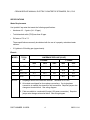
1
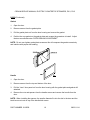
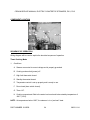
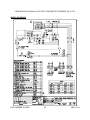
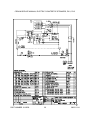
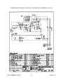
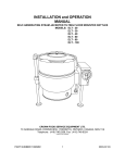
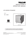
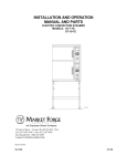
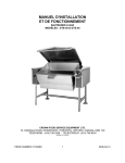
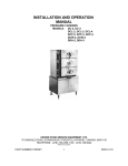
CROWN SERVICE MANUAL
ELECTRIC COUNTERTOP STEAMERS
MODELS: PX-3
PX-5
CROWN FOOD SERVICE EQUIPMENT LTD.
70 OAKDALE ROAD, DOWNSVIEW, (TORONTO), ONTARIO, M3N 1V9
TELEPHONE: (416) 746-2358, FAX: (416) 746-8324
PRINTED IN CANADA
PART NUMBER 10165R0
1
2005-11-24
CROWN SERVICE MANUAL, ELECTRIC COUNTERTOP STEAMERS, PX-3, PX-5
TABLE OF CONTENTS
GENERAL . . . . . . . . . . . . . . . . . . . . . . . . . . . . . . . . . . . . . . . . . . . . . . . . . . . . . . . . . . . . . . . . 3
Installation, Operation and Cleaning . . . . . . . . . . . . . . . . . . . . . . . . . . . . . . . . . . . . . . . . 3
Introduction . . . . . . . . . . . . . . . . . . . . . . . . . . . . . . . . . . . . . . . . . . . . . . . . . . . . . . . . . . 3
Features . . . . . . . . . . . . . . . . . . . . . . . . . . . . . . . . . . . . . . . . . . . . . . . . . . . . . . . . . . 3
Steam Cooking . . . . . . . . . . . . . . . . . . . . . . . . . . . . . . . . . . . . . . . . . . . . . . . . . . . . . 3
Model Designations . . . . . . . . . . . . . . . . . . . . . . . . . . . . . . . . . . . . . . . . . . . . . . . . . 3
Specifications . . . . . . . . . . . . . . . . . . . . . . . . . . . . . . . . . . . . . . . . . . . . . . . . . . . . . . . . . 4
Water Requirements . . . . . . . . . . . . . . . . . . . . . . . . . . . . . . . . . . . . . . . . . . . . . . . . 4
Electric . . . . . . . . . . . . . . . . . . . . . . . . . . . . . . . . . . . . . . . . . . . . . . . . . . . . . . . . . . . 4
Tools . . . . . . . . . . . . . . . . . . . . . . . . . . . . . . . . . . . . . . . . . . . . . . . . . . . . . . . . . . . . . . . 5
REMOVAL AND REPLACEMENT OF PARTS . . . . . . . . . . . . . . . . . . . . . . . . . . . . . . . . . . . . 5
Covers and Panels . . . . . . . . . . . . . . . . . . . . . . . . . . . . . . . . . . . . . . . . . . . . . . . . . . . . . 5
Component Panel Components . . . . . . . . . . . . . . . . . . . . . . . . . . . . . . . . . . . . . . . . . . . 6
Timer . . . . . . . . . . . . . . . . . . . . . . . . . . . . . . . . . . . . . . . . . . . . . . . . . . . . . . . . . . . . . . . 7
Standby Thermostat . . . . . . . . . . . . . . . . . . . . . . . . . . . . . . . . . . . . . . . . . . . . . . . . . . . . 7
High Limit Thermostat . . . . . . . . . . . . . . . . . . . . . . . . . . . . . . . . . . . . . . . . . . . . . . . . . . 8
Temperature Probe . . . . . . . . . . . . . . . . . . . . . . . . . . . . . . . . . . . . . . . . . . . . . . . . . . . . 9
Heating Element Assembly . . . . . . . . . . . . . . . . . . . . . . . . . . . . . . . . . . . . . . . . . . . . . 10
Manual Drain Valve . . . . . . . . . . . . . . . . . . . . . . . . . . . . . . . . . . . . . . . . . . . . . . . . . . . 13
Door . . . . . . . . . . . . . . . . . . . . . . . . . . . . . . . . . . . . . . . . . . . . . . . . . . . . . . . . . . . . . . . 15
SERVICE PROCEDURES AND ADJUSTMENTS . . . . . . . . . . . . . . . . . . . . . . . . . . . . . . . . .
Door Latch Adjustment . . . . . . . . . . . . . . . . . . . . . . . . . . . . . . . . . . . . . . . . . . . . . . . . .
Door Sealing Adjustment . . . . . . . . . . . . . . . . . . . . . . . . . . . . . . . . . . . . . . . . . . . . . . .
Heating Element Test . . . . . . . . . . . . . . . . . . . . . . . . . . . . . . . . . . . . . . . . . . . . . . . . . .
Temperature Control Calibration . . . . . . . . . . . . . . . . . . . . . . . . . . . . . . . . . . . . . . . . .
18
19
19
20
21
ELECTRIC OPERATION . . . . . . . . . . . . . . . . . . . . . . . . . . . . . . . . . . . . . . . . . . . . . . . . . . .
Component Function . . . . . . . . . . . . . . . . . . . . . . . . . . . . . . . . . . . . . . . . . . . . . . . . . .
Component Location . . . . . . . . . . . . . . . . . . . . . . . . . . . . . . . . . . . . . . . . . . . . . . . . . .
Sequence of Operation . . . . . . . . . . . . . . . . . . . . . . . . . . . . . . . . . . . . . . . . . . . . . . . .
Wiring Diagrams . . . . . . . . . . . . . . . . . . . . . . . . . . . . . . . . . . . . . . . . . . . . . . . . . . . . . .
23
23
24
24
29
TROUBLESHOOTING
. . . . . . . . . . . . . . . . . . . . . . . . . . . . . . . . . . . . . . . . . . . . . . . . . . . . . 32
CONDENSED SPARE PARTS LIST . . . . . . . . . . . . . . . . . . . . . . . . . . . . . . . . . . . . . . . . . . . 34
PART NUMBER 10165R0
2
2005-11-24
CROWN SERVICE MANUAL, ELECTRIC COUNTERTOP STEAMERS, PX-3, PX-5
GENERAL
INSTALLATION, OPERATION AND CLEANING
Refer to the Installation and Operation Manual for specific instructions.
NOTE: Daily cleaning is required.
INTRODUCTION
Features
•
Requires no water or drain line connections (manual fill and manual drain).
•
Cast aluminum “element block” for efficient heat transfer and distribution.
•
Field convertible to single phase or three phase power.
•
When wired for single phase, a reduced 2/3 power output is available.
Steam Cooking
The PX series steamer provides timed or continuous mode cooking in a “pressure-less”
compartment. The small physical size of the steamer offers an efficient way to produce many
foods in small batches. Pressure-less, convection steam cooking will steam cook fresh foods
or will steam, defrost and cook frozen foods providing the maximum colour, flavour and
nutritional value with the least expenditure of energy and labour. The “pressure-less” cooking
compartment allows the operator to open and close the door, any time during a cooking cycle.
Model Designations
•
•
PX-3 - 3 pan capacity*
PX-5 - 5 pan capacity*
* Based on 2.5 inch pan depth.
Exterior Dimensions
•
•
PX-3 - 21" w x 25" d x 25" h*
PX-5 - 21" w x 25" d x 31.5" h*
* Includes 4" legs and 2" steam vent height.
PART NUMBER 10165R0
3
2005-11-24
CROWN SERVICE MANUAL, ELECTRIC COUNTERTOP STEAMERS, PX-3, PX-5
SPECIFICATIONS
Water Requirements
Use “potable” tap water that meets the following specifications:
•
Hardness of 2 - 3 grains (34 - 35 ppm).
•
Total dissolved solids (TDS) less than 60 ppm.
•
Ph factor of 7.0 to 7.5.
These specifications can easily be obtained with the use of a properly maintained water
softener.
•
2.5 gallons to fill holding pan (approximate).
Electric
MODEL
PX-3
TOTAL
kW
9.0 STD.
6.0³
PX-5
15.0 STD.
10.0³
NOTES:
AMPERAGE PER LINE (60 HZ)¹
3 PHASE²
1 PHASE²
208V
240V
480V
208V
240V
25
21.7
10.9
43.3
37.5
-
-
-
28.9
25
41.7
36.1
18.1
72.2
62.5
-
-
-
48.1
41.7
1. Amperage values in the table are nominal. Tolerance is +5/-10%.
2. All models are shipped for three phase connections. If a single phase
connection is needed, the steamer is field convertible. Requires jumper wire
changes at terminal block. See wiring diagram.
3. Field convertible to a reduced kW output (2/3 power connection). Requires
jumper wire changes at terminal block. See wiring diagram.
PART NUMBER 10165R0
4
2005-11-24
CROWN SERVICE MANUAL, ELECTRIC COUNTERTOP STEAMERS, PX-3, PX-5
TOOLS
Standard
•
Standard set of hand tools.
•
Clear silicone sealant.
•
VOM with an AC current tester (any quality VOM with a sensitivity of at least 20,000 ohms
per volt can be used).
•
Temperature meter and thermocouple.
Special
•
Thermal Transfer Compound, Dow Corning 340, P/N 4917-1 or equivalent.
NOTE: The additional tools below are required if replacing heating element assembly.
•
Torque wrench (in - lb.)
•
Tile Trowel 3/16" x 5/32" V notch.
•
Loctite 271 or equivalent.
REMOVAL AND REPLACEMENT OF PARTS
COVERS AND PANELS
WARNING: DISCONNECT THE ELECTRICAL POWER TO THE MACHINE AT THE MAIN
CIRCUIT BOX. PLACE A TAG ON THE CIRCUIT BOX INDICATING THE CIRCUIT IS BEING
SERVICED.
Right Side Panel
1. Remove screws from bottom of panel.
2. Slide panel down to clear top cover.
3. Reverse procedure to install.
PART NUMBER 10165R0
5
2005-11-24
CROWN SERVICE MANUAL, ELECTRIC COUNTERTOP STEAMERS, PX-3, PX-5
Top Cover
1. Remove screws from the top rear of cover.
2. Push up on rear of cover to clear steam vent pipe and slide forward to clear the front lip.
3. Lift the cover off the cabinet.
4. Reverse procedure to install.
Left Side and Rear Panel
1. Remove top cover as outlined under “TOP COVER”.
2. Disconnect electrical supply at terminal block.
3. Remove screws at bottom of panel.
4. Pull the combination left side and rear panel off.
5. Reverse procedure to install.
Lower Front Cover
1. Remove screws from the lower front cover.
2. Open the door, cut the bead of silicone at the top rear of cover then remove cover.
3. Clean silicone residue from mating surfaces.
4. Reverse procedure to install and apply silicone sealant at the top rear of cover.
COMPONENT PANEL COMPONENTS
WARNING: DISCONNECT THE ELECTRICAL POWER TO THE MACHINE AT THE MAIN
CIRCUIT BOX. PLACE A TAG ON THE CIRCUIT BOX INDICATING THE CIRCUIT IS BEING
SERVICED.
1. Remove right side panel as outlined under “COVERS AND PANELS”.
2. Disconnect lead wires to component being replaced.
3. Remove component.
PART NUMBER 10165R0
6
2005-11-24
CROWN SERVICE MANUAL, ELECTRIC COUNTERTOP STEAMERS, PX-3, PX-5
COMPONENT PANEL COMPONENTS (Continued)
NOTE: If replacing temperature control, see “TEMPERATURE CONTROL CALIBRATION ADJUSTMENT FOR ELEVATION” in “SERVICE PROCEDURES AND ADJUSTMENTS”.
TIMER
WARNING: DISCONNECT THE ELECTRICAL POWER TO THE MACHINE AT THE MAIN
CIRCUIT BOX. PLACE A TAG ON THE CIRCUIT BOX INDICATING THE CIRCUIT IS BEING
SERVICED.
1. Remove right side panel as outlined under “COVERS AND PANELS”.
2. Disconnect lead wires to timer.
3. Loosen two set screws on dial and pull timer knob from shaft.
4. Remove nut from timer shaft and remove timer.
5. Reverse procedure to install.
STANDBY THERMOSTAT
WARNING: DISCONNECT THE ELECTRICAL POWER TO THE MACHINE AT THE MAIN
CIRCUIT BOX. PLACE A TAG ON THE CIRCUIT BOX INDICATING THE CIRCUIT IS BEING
SERVICED.
1. Remove right side panel as outlined under “COVERS AND PANELS”.
2. Pull insulation back to expose standby thermostat and disconnect lead wires.
PART NUMBER 10165R0
7
2005-11-24
CROWN SERVICE MANUAL, ELECTRIC COUNTERTOP STEAMERS, PX-3, PX-5
STANDBY THERMOSTAT (Continued)
3. Grasp thermostat body and push up to slide holding tabs out from mounting bracket.
4. Apply a small amount of “thermal transfer compound” to the mating surface (disk side) of
the replacement thermostat.
A. Spread the compound completely and evenly over the surface of the thermostat.
5. Reverse procedure from step 3 to install and check steamer for proper operation.
HIGH LIMIT THERMOSTAT
WARNING: DISCONNECT THE ELECTRICAL POWER TO THE MACHINE AT THE MAIN
CIRCUIT BOX. PLACE A TAG ON THE CIRCUIT BOX INDICATING THE CIRCUIT IS BEING
SERVICED.
1. Remove right side panel as outlined under “COVERS AND PANELS”.
2. Pull insulation back to expose high limit thermostat and disconnect lead wires.
PART NUMBER 10165R0
8
2005-11-24
CROWN SERVICE MANUAL, ELECTRIC COUNTERTOP STEAMERS, PX-3, PX-5
HIGH LIMIT THERMOSTAT (Continued)
3. Remove thermostat from heating element assembly.
NOTE: Thermostat base is a brass 5/8" hex with a threaded stem.
4. Apply a small amount of “thermal transfer compound” to the mating surface (disk side) of
the replacement thermostat.
A. Spread the compound completely and evenly over the surface of the thermostat.
5. Reverse procedure from step 3 to install and check steamer for proper operation.
NOTE: Do not cross thread or over tighten the high limit or damage to the mounting threads
may occur.
TEMPERATURE PROBE
WARNING: DISCONNECT THE ELECTRICAL POWER TO THE MACHINE AT THE MAIN
CIRCUIT BOX. PLACE A TAG ON THE CIRCUIT BOX INDICATING THE CIRCUIT IS BEING
SERVICED.
1. Remove all covers and panels as outlined under “COVERS AND PANELS”.
2. Disconnect probe leads from the temperature control.
3. Remove temperature probe from steam vent pipe.
PART NUMBER 10165R0
9
2005-11-24
CROWN SERVICE MANUAL, ELECTRIC COUNTERTOP STEAMERS, PX-3, PX-5
TEMPERATURE PROBE (Continued)
4. Reverse procedure to install replacement probe.
5. Adjust temperature control as outlined under “TEMPERATURE CONTROL CALIBRATION”
in ‘SERVICE PROCEDURES AND ADJUSTMENTS”.
HEATING ELEMENT ASSEMBLY
WARNING: DISCONNECT THE ELECTRICAL POWER TO THE MACHINE AT THE MAIN
CIRCUIT BOX. PLACE A TAG ON THE CIRCUIT BOX INDICATING THE CIRCUIT IS BEING
SERVICED.
The heating element assembly contains three elements molded into a cast aluminum block.
The block is mounted on the underside of cooking compartment.
NOTE: As the steamer is disassembled, remove the sheets of insulation from top, rear and left
side, and the bottom. Retain insulation for use during re-assembly.
1.
Remove all covers and panels as outlined under “COVERS AND PANELS”.
2.
From the rear, tilt steamer until it rests on door.
A.
3.
Place wooden blocks opposite door handle to level and support steamer.
Grasp component panel and remove screws securing it to the base.
A.
Lower component panel and leave at the side of steamer so that all the component
lead wires can remain connected.
4.
Remove screws securing base to steamer support frame.
5.
Remove mounting nuts and washers from the rear cooking compartment support legs and
remove base.
PART NUMBER 10165R0
10
2005-11-24
CROWN SERVICE MANUAL, ELECTRIC COUNTERTOP STEAMERS, PX-3, PX-5
HEATING ELEMENT ASSEMBLY (Continued)
6.
Disconnect heating element lead wires from element terminals.
7.
Disconnect high limit thermostat lead wires and remove high limit from heating element
assembly.
PART NUMBER 10165R0
11
2005-11-24
CROWN SERVICE MANUAL, ELECTRIC COUNTERTOP STEAMERS, PX-3, PX-5
HEATING ELEMENT ASSEMBLY (Continued)
8.
Remove heating element assembly from steamer by removing nuts and washers from
mounting studs.
9.
Clean Loctite residue from heating element assembly mounting stud threads.
10. Apply approximately 4 oz. of heat transfer compound to the mating surface (side opposite
markings) on the heating element assembly.
A. Using a tile trowel, spread the compound evenly over the surface of the assembly.
11. Mount replacement heating element assembly to the underside of cooking compartment.
A.
Temporarily install a flat washer and nut on all mounting studs. Hand tighten only.
B.
Tighten each nut to 100 in-lb using the sequence as shown.
12.
PART NUMBER 10165R0
C.
Remove nut and washer from each mounting stud.
D.
Apply Loctite 271 to heating element assembly mounting stud
threads.
E.
Stack two new spring disk washers (Belleville) together and
install on each stud.
1) Tighten each nut to 45 in-lb using the same sequence as
shown.
Reverse procedure to re-assemble from step 7 and check
steamer for proper operation.
12
2005-11-24
CROWN SERVICE MANUAL, ELECTRIC COUNTERTOP STEAMERS, PX-3, PX-5
MANUAL DRAIN VALVE
WARNING: DISCONNECT THE ELECTRICAL POWER TO THE MACHINE AT THE MAIN
CIRCUIT BOX. PLACE A TAG ON THE CIRCUIT BOX INDICATING THE CIRCUIT IS BEING
SERVICED.
1.
Remove all covers and panels as outlined under “COVERS AND PANELS”.
2.
From the rear, tilt steamer until it rests on door.
A. Place wooden blocks opposite door handle to level and support steamer.
3.
Grasp component panel and remove screws securing it to the base.
A. Lower component panel and leave at side of steamer so that all the component lead
wires can remain connected.
4.
Remove screws securing base to steamer support frame.
5.
Remove mounting nuts and washers from the rear cooking compartment support legs and
remove base.
6.
Remove outer nut on drain valve stem and lift off drain handle assembly.
PART NUMBER 10165R0
13
2005-11-24
CROWN SERVICE MANUAL, ELECTRIC COUNTERTOP STEAMERS, PX-3, PX-5
MANUAL DRAIN VALVE (Continued)
7.
Remove manual drain valve from cooking compartment drain pipe.
8.
Clean thread sealant residue from drain pipe threads and apply new sealant.
9.
Install a replacement drain valve.
A. Tighten valve body so that actuator stem is pointing towards front of steamer.
10. Reverse procedure to re-assemble from step 6 and check steamer for proper operation.
PART NUMBER 10165R0
14
2005-11-24
CROWN SERVICE MANUAL, ELECTRIC COUNTERTOP STEAMERS, PX-3, PX-5
DOOR
WARNING: DISCONNECT THE ELECTRICAL POWER TO THE MACHINE AT THE MAIN
CIRCUIT BOX. PLACE A TAG ON THE CIRCUIT BOX INDICATING THE CIRCUIT IS BEING
SERVICED.
Removal
1.
Remove top cover as outlined under “COVERS AND PANELS”.
2.
Open the door.
3.
Pull hinge rod up.
4.
Reverse procedure to install, making sure the door bushings and spacer are in place.
PART NUMBER 10165R0
15
2005-11-24
CROWN SERVICE MANUAL, ELECTRIC COUNTERTOP STEAMERS, PX-3, PX-5
DOOR (Continued)
Gasket
1.
Open the door.
2.
Remove screws from the gasket plate.
3.
Pull the gasket plate out from the door housing and remove the gasket.
4.
Position the new gasket on the gasket plate and reverse the procedure to install. Adjust
the door as outlined under “DOOR SEALING ADJUSTMENT”.
NOTE: Do not over tighten gasket plate screws as this will compress the gasket excessively
and interfere with proper door sealing.
Handle
1.
Open the door.
2.
Remove screws from the top and bottom of the door.
3.
Pull the “inner” door panel out from the door housing with the gasket plate and gasket still
attached.
4.
Remove the nuts and spacers from the handle screws and remove the handle from the
door.
NOTE: When installing the spacers, the smaller diameter fits into the slot in the door and the
latch lever must rest on top of the handle latch screw.
PART NUMBER 10165R0
16
2005-11-24
CROWN SERVICE MANUAL, ELECTRIC COUNTERTOP STEAMERS, PX-3, PX-5
Handle (Continued)
5.
Reverse procedure to install.
Latch Assembly
1.
Open the door.
2.
Remove screws from the top and bottom of the door.
3.
Pull the “inner” door panel out from the door housing with the gasket plate and gasket still
attached.
4.
Remove the screws from the side edge of the door that secure the latch mechanism and
remove the latch from the door.
PART NUMBER 10165R0
17
2005-11-24
CROWN SERVICE MANUAL, ELECTRIC COUNTERTOP STEAMERS, PX-3, PX-5
Latch Assembly (Continued)
NOTE: When installing, the latch lever must rest on top of the handle latch screw.
5.
Reverse procedure to install.
SERVICE PROCEDURES AND ADJUSTMENTS
WARNING: CERTAIN PROCEDURES IN THIS SECTION REQUIRE ELECTRICAL TEST OR
MEASUREMENTS WHILE POWER IS APPLIED TO THE MACHINE. EXERCISE EXTREME
CAUTION AT ALL TIMES. IF TEST POINTS ARE NOT EASILY ACCESSIBLE, DISCONNECT
POWER, ATTACH TEST EQUIPMENT AND REAPPLY POWER TO TEST.
PART NUMBER 10165R0
18
2005-11-24
CROWN SERVICE MANUAL, ELECTRIC COUNTERTOP STEAMERS, PX-3, PX-5
DOOR LATCH ADJUSTMENT
Should the steamer door “jam” and cannot be opened, DO NOT FORCE OR PRY the door as
damage will occur.
First, try lifting up on the bottom of the door at the handle end, to disengage the latch.
If that does not work, remove the right side panel. The striker that catches on the “door latch” is
located behind the front face of the cooking cavity. Remove the nut from the striker. This will
release it from the panel.
Once the nut and washer have been removed, door will open freely.
Remove any burrs on the striker that may cause the latch to stick.
Reinstall the striker and adjust, so door will not jam.
To adjust:
1.
Reinstall he striker with the slot pointing upwards and “hand tighten” nut only.
2.
Close the door to center the striker in the oval mounting hole.
3.
Open the door and check the strikers’ slot for horizontal alignment. The slot on the striker
must be kept horizontal in order for the door latch to catch it properly and latch.
4.
Once the proper slot alignment has been set, hold the striker close to its base using a rag
and vise grips, then tighten the striker nut. Be careful not to damage the striker “slot” when
tightening or door may not latch properly.
NOTE: Do not over tighten as the striker will begin to turn and change alignment.
DOOR SEALING ADJUSTMENT
On initial installation of new door gaskets, the door will be hard to close. This is required for
proper gasket fit. As the door is used, it becomes easier to close after a few days.
1.
Check the door gasket quality. If damaged or worn, replace as outlined under “DOOR”.
2.
Loosen screws until the screw heads no longer touch the gasket plate.
3.
Tighten screws until screw head touches gasket plate and at that point begin counting
turns.
PART NUMBER 10165R0
19
2005-11-24
CROWN SERVICE MANUAL, ELECTRIC COUNTERTOP STEAMERS, PX-3, PX-5
Door Sealing Adjustment (Continued)
4.
Tighten all screws approximately two turns.
5.
Close the door and check unit for proper operation.
6.
If necessary, tighten all screws an additional ½ turn and repeat step 5.
7.
Repeat step 6 until the door closes properly and no steam “leaks” are seen around the
gasket seal.
HEATING ELEMENT TEST
WARNING: THE FOLLOWING STEPS REQUIRE POWER TO BE APPLIED TO THE UNIT
DURING THE TEST. USE EXTREME CAUTION AT ALL TIMES.
1.
Turn cooking mode switch to “continuous”.
2.
Measure voltage at heating element terminals and verify it against data plate voltage.
A. If voltage is incorrect, find the source of the problem.
B. If voltage is correct, check current draw (amps) through the heating element lead wires.
NOTE: This method is preferred over a resistance check when a clamp on type amp meter is
available.
1) If current draw is correct then heating element is functioning properly. See
table below for proper values.
2) If current draw is not correct, turn cooking mode switch to OFF and
disconnect the electrical supply.
a. Replace heating element then proceed to step 3.
C. If unable to check current draw, a resistance check may indicate a malfunctioning
element.
1) Turn the cooking mode switch to OFF and disconnect the electrical supply.
2) Remove the lead wires from the heating element and check resistance (ohms). See
table below for proper values.
3. Check for proper operation.
PART NUMBER 10165R0
20
2005-11-24
CROWN SERVICE MANUAL, ELECTRIC COUNTERTOP STEAMERS, PX-3, PX-5
VOLTAGE
kW PER
ELEMENT
AMPS PER ELEMENT
1 PH
3 PH
OHMS PER
ELEMENT
208
3
14.4
8.3
14.4
240
3
12.5
7.2
19.2
480
3
3.6
76.8
208
5
24
14
8.7
240
5
21
12
11.5
480
5
6
46
NOTES:
1.
Values in the table are nominal. Tolerance is +5/-10%.
2.
Voltage values are @ 60 HZ.
3.
Each heating element assembly contains 3 elements. Total kW
would be the individual element kW times 3.
4.
Resistance values (ohms) are at room temperature.
TEMPERATURE CONTROL CALIBRATION
To set the temperature control for optimum steamer operation, the elevation above sea level for
the service location must first be determined.
The elevation is used in conjunction with the elevation table below, to determine the correct set
point temperature for the control.
NOTE: If the set point temperature is too high, the excess boiling action will cause water
droplets to exit the steam vent pipe, and cause high water usage.
1.
Remove right side panel as outlined under “COVERS AND PANELS”.
2.
Place a thermocouple approximately one inch down in the center of steam vent pipe.
3.
Turn steamer on by selecting “continuous” mode.
PART NUMBER 10165R0
21
2005-11-24
CROWN SERVICE MANUAL, ELECTRIC COUNTERTOP STEAMERS, PX-3, PX-5
TEMPERATURE CONTROL CALIBRATION (Continued)
4.
Allow steamer temperature to stabilize by completing two heating cycles.
5.
Record the temperature reading when “heater” light goes out.
6.
Using the elevation table, compare the recorded temperature to the temperature listed for
the specific elevation.
NOTE: Use temperature scale on control for reference only. The scale represents dial turns in
1°F increments, not the actual temperature. When calibrating, use the recorded temperature
taken from thermocouple.
ELEVATION (FT)
TEMPERATURE (°F)
Sea Level
210
1000
208
2000
206
3000
204
4000
202
5000
200
6000
198
7000
196
8000
195
9,000 or above
194
A. If the set point temperature of the control is correct, no adjustment is necessary.
B. If the set point temperature of the control is not correct, adjust the temperature control.
Repeat step 4 until the correct temperature is achieved.
1) Turn the temperature control dial clockwise to increase temperature or
counterclockwise to decrease temperature.
PART NUMBER 10165R0
22
2005-11-24
CROWN SERVICE MANUAL, ELECTRIC COUNTERTOP STEAMERS, PX-3, PX-5
ELECTRICAL OPERATION
COMPONENT FUNCTION
Buzzer .............................. Signals end of a “cook” cycle when cooking time expires.
Contactor ......................... Supplies line voltage to heating element assembly.
Relay R1 ............................. Supplies power to temperature control.
Transformer ....................... Provides 240V to the control circuit (480V only).
Heater Light (Green) ......... Indicates steamer is heating.
Low Water Light (Red)....... Indicates additional water is required in cooking compartment.
Cooking Mode Switch
(With Pilot Lights).............. Supplies 240V to the control circuit. Two internal “pilot” lights
indicate the cooking mode selected. Timed mode is amber;
Continuous mode is red.
Door Switch ..................... Removes control circuit power from steamer when door is
opened.
High Limit Thermostat ..... Protects steamer by removing control circuit power if the heating
element assembly temperature goes above 350°F (+/-15; 50°F
differential).
Temperature Control........ Monitors temperature probe and cycles power to heater contactor
for steam generation.
Standby Thermostat.......... Maintains steamer at a standby temperature of 168°F (+5/-8)
when “cook” timer is off (timed mode only).
Timer ................................ Counts “cook” time of product when time is dialed and energizes
buzzer when time expires. To silence buzzer, dial must be turned
to off.
Temperature Probe ......... Senses cooking compartment temperature and sends a
corresponding DC voltage back to the temperature control (J-type
thermocouple).
PART NUMBER 10165R0
23
2005-11-24
CROWN SERVICE MANUAL, ELECTRIC COUNTERTOP STEAMERS, PX-3, PX-5
COMPONENT LOCATION
SEQUENCE OF OPERATION
Wiring diagram will be used to explain the electrical sequence of operation.
Timed Cooking Mode
1.
Conditions.
A. Steamer connected to correct voltage and is properly grounded.
B. Cooking mode switch (power) off.
C. High limit thermostat closed.
D. Standby thermostat closed.
E. Temperature control is set up properly and is ready to use.
F. Door closed (door switch closed).
G. Timer “off”.
H. Cooking compartment filled to the water level mark and below standby temperature of
168°F (+5/-8).
NOTE: At temperatures below 168°F, the steamer is in a “pre-heat” state.
PART NUMBER 10165R0
24
2005-11-24
CROWN SERVICE MANUAL, ELECTRIC COUNTERTOP STEAMERS, PX-3, PX-5
SEQUENCE OF OPERATION (Continued)
2.
Select “timed” on the cooking mode switch.
A. Internal “pilot” light (top, amber) comes on.
B. Internal “pilot” light (bottom, red) comes on.
C. Relay “R1" energized.
1) R1-2A and R1-2B (both N.C.) open.
2) R1-3A and R1-3B (both N.O.) close.
3.
Temperature control energized and evaluates input from thermocouple.
A. With temperature below set point, internal relay contacts close.
1) Heater light (green) comes on.
2) Contactor energized and heating elements are powered.
4.
Temperature reaches 168°F and standby thermostat opens.
A. Internal “pilot” light (top, amber) goes out.
NOTE: Steamer will maintain standby temperature until a “cook” time is dialed on timer; or
the cooking mode switch is turned to off or continuous; or the door is opened.
B. Relay “R1" de-energized.
1) R1-2A & R1-2B return to N.C. position.
2) R1-3A & R1-3B return to N.O. position.
a) Temperature control de-energized and internal relay contacts open.
b) Contactor de-energized and power removed from heating elements.
5. Set “cook” timer to desired time.
A. Timer contacts 1 and 3 close, timer motor is energized and timing down begins.
PART NUMBER 10165R0
25
2005-11-24
CROWN SERVICE MANUAL, ELECTRIC COUNTERTOP STEAMERS, PX-3, PX-5
SEQUENCE OF OPERATION (Continued)
NOTE: Additional time can be set or the “cook” timer can be turned off throughout the cooking
cycle. If turned to off, steamer reverts to standby temperature.
6. Temperature reaches set point and the temperature control’s internal relay contacts open.
A. Contactor de-energized and power is removed from heating elements.
7. Steamer cycles on the temperature control until “cook” time expires.
8. Time expires on “cook” timer.
A. Timer contacts 1 and 3 open, timer motor is de-energized and timing stops.
B. Timer contacts 1 and 4 close.
1) Buzzer energized and sounds.
NOTE:
The buzzer continues to sound until timer dial is set to off position or additional time
is set.
9. Turn “cook” timer off.
A. Steamer reverts to standby temperature and continues to cycle until a “cook” time is
dialed on timer; or the cooking mode switch is turned to off or continuous; or the door is
opened.
NOTE: If water level becomes low during cycling, high limit thermostat will open and low
water light (red) will come on.
PART NUMBER 10165R0
26
2005-11-24
CROWN SERVICE MANUAL, ELECTRIC COUNTERTOP STEAMERS, PX-3, PX-5
Continuous Cooking Mode
1. Conditions.
A. Steamer connected to correct voltage and is properly grounded.
B. Cooking mode switch (power) off.
C. High limit thermostat closed.
D. Standby thermostat closed.
E. Temperature control is set up properly and is ready to use.
F. Door closed (door switch closed).
G. Timer “off”.
H. Cooking compartment filled to the water level mark and below standby temperature of
168°F (+5/-8).
2. Select “continuous” on the cooking mode switch.
A. Internal “pilot” light (top, amber) comes on.
B. Internal “pilot” light (bottom, red) comes on.
C. Relay “R1" energized.
1) R1-2A and R1-2B (both N.C.) open.
2) R1-3A and R1-3B (both N.O.) close.
3. Temperature control energized and evaluates input from thermocouple.
A. With temperature below set point, internal relay contacts close.
1) Heater light (green) comes on.
2) Contactor energized and heating elements are powered.
4. Temperature reaches 168°F and standby thermostat opens.
A. Internal “pilot” light (top, amber) goes out.
PART NUMBER 10165R0
27
2005-11-24
CROWN SERVICE MANUAL, ELECTRIC COUNTERTOP STEAMERS, PX-3, PX-5
Continuous Cooking Mode (Continued)
NOTE: Standby thermostat does not affect continuous mode operation and the “cook” timer is
not used.
5. Temperature reaches set point and the temperature control’s internal relay contacts open.
A. Contactor de-energized and power is removed from heating elements.
6. Steamer continues to cycle on the temperature control until the cooking mode switch is
turned to off or timed; or the door is opened.
NOTE: If water level becomes low during cycling, high limit thermostat will open and low water
light (red) will come on.
PART NUMBER 10165R0
28
2005-11-24
CROWN SERVICE MANUAL, ELECTRIC COUNTERTOP STEAMERS, PX-3, PX-5
WIRING DIAGRAMS
PART NUMBER 10165R0
29
2005-11-24
CROWN SERVICE MANUAL, ELECTRIC COUNTERTOP STEAMERS, PX-3, PX-5
PART NUMBER 10165R0
30
2005-11-24
CROWN SERVICE MANUAL, ELECTRIC COUNTERTOP STEAMERS, PX-3, PX-5
PART NUMBER 10165R0
31
2005-11-24
CROWN SERVICE MANUAL, ELECTRIC COUNTERTOP STEAMERS, PX-3, PX-5
TROUBLESHOOTING
WARNING: CERTAIN PROCEDURES IN THIS SECTION REQUIRE ELECTRICAL TESTS
OR MEASUREMENTS WHILE POWER IS APPLIED TO THE MACHINE. EXERCISE
EXTREME CAUTION AT ALL TIMES. IF TEST POINTS ARE NOT EASILY ACCESSIBLE,
DISCONNECT POWER, ATTACH TEST EQUIPMENT AND REAPPLY POWER TO TEST.
SYMPTOM
POSSIBLE CAUSES
Compartment leaks water around door.
1. Steamer not level.
2. Steamer overfilled.
Steam leaks around door.
1. Worn gasket. See “DOOR” in “SERVICE
PROCEDURES AND ADJUSTMENTS’.
2. Damaged gasket.
3. Steam vent pipe blocked.
Steam generated inside compartment when
timer is off.
1. Timer malfunction.
2. Contactor malfunction.
3. Temperature control malfunction (heater
light on.)
Steamer will not heat (heat light off).
1. Line voltage incorrect.
2. Control circuit fuse(s) open.
3. High limit thermostat open (low water
light on).
4. Door open or door switch malfunction.
5. Cooking mode switch off or inoperative.
6. Relay R1 malfunction.
7. Timer malfunction (timed mode only).
8. Temperature probe malfunction.
9. Temperature control malfunction.
Steamer will not heat (heat light on).
1. Line voltage incorrect.
2. Heating element malfunction.
3. Contactor malfunction.
Timer motor does not run.
1. Door open or door switch malfunction.
2. Relay R1 malfunction.
3. Timer inoperative.
Door not closing properly.
1. Door latch assembly.
2. Striker adjustment.
3. Steamer pan not inserted properly.
PART NUMBER 10165R0
32
2005-11-24
CROWN SERVICE MANUAL, ELECTRIC COUNTERTOP STEAMERS, PX-3, PX-5
SYMPTOM
POSSIBLE CAUSES
Door won’t open.
1. Latch won’t release. See “DOOR LATCH
ADJUSTMENT” in “SERVICE
PROCEDURES AND ADJUSTMENTS”.
Buzzer not operating.
1. Timer malfunction.
2. Buzzer malfunction.
Water spraying out of steam vent pipe during
a “cook” cycle.
1. Temperature control calibration too high.
See “TEMPERATURE CONTROL
CALIBRATION - ADJUSTMENT FOR
ELEVATION” in ‘SERVICE
PROCEDURES AND ADJUSTMENTS”.
2. Temperature probe malfunction.
3. Temperature control malfunction.
4. Contactor malfunction.
High water usage.
1. Temperature control calibration too high.
See “TEMPERATURE CONTROL
CALIBRATION - ADJUSTMENT FOR
ELEVATION” in “SERVICE
PROCEDURES AND ADJUSTMENTS”.
2. Temperature probe malfunction.
3. Temperature control malfunction.
4. Steamer operating in “continuous” mode.
Excessive or inconsistent “cook” times.
1.
2.
3.
4.
PART NUMBER 10165R0
33
Door left open between loads.
Temperature control calibration too low.
Heating element malfunction.
Standby thermostat malfunction.
2005-11-24
CROWN SERVICE MANUAL, ELECTRIC COUNTERTOP STEAMERS, PX-3, PX-5
CONDENSED SPARE PARTS LIST
PX-3 and PX-5
PART
NUMBER
DESCRIPTION
NOTES
8-5063-8
Door Gasket (PX-5)
8-5063-9
Door Gasket (PX-3)
9-3213
Door Switch
9143-1
Thermostat - Temperature Control
9077-1
Thermostat - Standby
9080-1
Thermocouple Sensor, J-Type
9068-1
Fuse Block
9092-1
Fuse, 1 Amp., 250V (208/240V)
4916-1
Contactor (208/240V)
4914-1
High Limit Thermostat
9124-1
Power Switch (Cooking Mode Switch)
38595
Element Assembly, 208V, 9 kW
38600
Element Assembly, 208V, 15 kW
38597
Element Assembly, 240V, 415V, 9 kW
38602
Element Assembly, 240V, 415V, 15 kW
38596
Element, 220V, 380V, 9 kW
38601
Element, 220V, 380V, 15 kW
38598
Element, 480V, (277V), 9 kW
38603
Element, 480V, (277V), 15 kW
38599
Element, 600V, (347V), 9 kW
38604
Element, 600V, (347V), 15 kW
4-T209-1
Timer, 60 Minutes
9001-3
Fuse, 1A, (380V - 480V)
9001-5
Fuse, 8/10A, (600V)
PART NUMBER 10165R0
34
2005-11-24
CROWN SERVICE MANUAL, ELECTRIC COUNTERTOP STEAMERS, PX-3, PX-5
PX-3 and PX-5
PART
NUMBER
DESCRIPTION
NOTES
9002-1
Fuse Holder (380V - 600V)
4-NG41
Contactor (380V - 600V)
4-T251
Transformer, 380/415 - 220/240V, 100VA
4-T255
Transformer, 480 - 240V, 100 VA
4-T260
Transformer, 600 - 240V, 100 VA
PART NUMBER 10165R0
35
2005-11-24
CROWN SERVICE MANUAL, ELECTRIC COUNTERTOP STEAMERS, PX-3, PX-5
Revision History
Revision
Revised
By
Pages
Affected
Brian
All
Effective
Date
Mar. 15,
2005
Comments
New Crown Service Manual. Originally
created for Vulcan.
ALTERNATE PARTS
Page
Item
Crown
Blodgett
Southbend
Market Forge
Vulcan
Hobart
Document Responsibility
PART NUMBER 10165R0
36
2005-11-24
CROWN SERVICE MANUAL, ELECTRIC COUNTERTOP STEAMERS, PX-3, PX-5
Responsibility
Name
Title
Original Document
Production,
Archives, Distribution
Lorie
Marcocchio
Engineering Clerk
Content
Development,
Revision Maintenance
Brian Walters
Technical Service Manager
Agency Requirements
Val
Chlistovsky
Approvals & Quality
Engineer, ISO
Technical Illustration
Tony Cordeiro
CAD Draftsman
Spare Parts Price List
Domenic
Caputi
Sales Coordinator,
Equipment & Parts
Document Review
John Derdall
Manager, Production
Engineering - Quality
Assurance
PART NUMBER 10165R0
37
Signature
2005-11-24
CROWN SERVICE MANUAL, ELECTRIC COUNTERTOP STEAMERS, PX-3, PX-5
Distribution
CROWN FOOD SERVICE EQUIPMENT LTD.
VULCAN-HART COMPANY, Troy, Ohio, U.S.A.
Models: VPX3, VPX5
HOBART
Models: HPX3, HPX5
PART NUMBER 10165R0
38
2005-11-24