1
SpotCell ® 2500Xl User Manual
Technical Support
SpotCell® serial numbers must be available to authorize technical support and/or to establish a
return authorization for defective units. The serial numbers are located on the back of the Coverage
Unit (CU) and the Donor Unit (DU), as well as on the box in which they were delivered. Additional
support information may be obtained by accessing the Spotwave Wireless Inc. website at
www.spotwave.com. To contact support by telephone, call your local Spotwave vendor; or if you
are unable to reach your vendor, contact Spotwave Wireless at 866-704-9750.
Important Safety Information
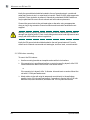
Warning! For your safety, beware of power lines and ensure appropriate safety measures are
maintained at all times during the installation of the SpotCell equipment. If equipment not shipped
with the SpotCell system is to be used during installation or mounting, follow all equipment
manufacturer’s instructions in proper use to ensure injury is avoided.
The DU and CU of the SpotCell are low power transmitters. As with a cell phone antenna, avoid
unneccessary contact with the front of the units when they units are operating. Mount the units in a
location where people will not approach within 1 meter of the front of the DU and 20 centimeters in
front of the CU.
When deploying the extended coverage antenna, there must be a minimum separation of 10 cm
between the main CU and the extended coverage antenna with the antennas facing in opposite
directions. The extended coverage antenna should be mounted in locations where people will not
approach within 20 cm in front of the antenna.
This manual outlines installation instructions and the appendix offers practical safety tips (see
Appendix E entitled ‘Safety Hints’).
If you are not sure about a safe installation, do not attempt to install it yourself. Call a professional
installer for help.
LIMITED WARRANTY AND LIMITATION OF LIABILITY:
1. What is Covered and for How Long?
Spotwave Wireless Inc. ("Spotwave") warrants to the original Purchaser that the Spotwave SpotCell System (the
"System") is free from defects in material and workmanship under normal use and service for a period of 12 months from the date of shipment from Spotwave
(the "Limited Warranty Period").
2. What is not covered? This Limited Warranty is conditioned upon proper use of the System by the Purchaser. This Limited Warranty does not cover (and
will become null and void in the event of): (a) defects or damage resulting from accident, misuse, abuse, neglect, unusual physical, electrical or
electromechanical stress, modification of the System or any part thereof, or cosmetic damage; (b) removal, alteration or defacing of the serial number or other
identifying marks on the System; (c) all plastic surfaces and other externally exposed components that are scratched or damaged due to normal use; (d)
malfunctions resulting from the use of the System in conjunction with accessories, products or (ancillary) or peripheral equipment not provided by Spotwave;
or (e) defects or damage from unauthorized or improper testing, operation, maintenance, installation, servicing or adjustment of the System. Any repairs or
replacements provided by Spotwave outside of the Limited Warranty Period (including repairs to or replacement after the end of the Warranty Period), or in
excess of the services provided during the Limited Warranty Period, will subject to Spotwave's then prevailing rates.
3. What are Spotwave's Obligations and how do you make a claim? During the Limited Warranty Period, Spotwave will repair or replace, at Spotwave's sole
option, without charge to Purchaser, any defective component of the System, provided that the System is returned promptly upon discovery of the defect
and during the Limited Warranty Period. To obtain service, Systems must be returned to an authorized service facility in the original packaging or packaging
adequate for shipping, accompanied by Purchaser's sales receipt or comparable substitute proof of sale showing the date of purchase and the serial number
of the System. A valid RMA is required prior to any return.
To locate your nearest authorized service facility, call Spotwave Customer Service at 1-866-704-9750. Spotwave may, at Spotwave's sole option, use rebuilt,
reconditioned, or new parts or components when repairing any System or replace a System with a rebuilt, reconditioned or new System. Repaired Systems
LIMITED WARRANTY AND LIMITATION OF LIABILITY:
will be warranted for a period equal to the remainder of the original Limited Warranty Period for the original System or for 90 days,
whichever is longer. All replaced parts, components, boards or equipment shall become the property of Spotwave. If Spotwave
determines that any System is not covered by this Limited Warranty, Purchaser must pay the costs for all parts, shipping, and labor charges
for the repair or return of such System.
4. What are the Limits on Spotwave's Liability?
EXCEPT FOR THE WARRANTY IN PARAGRAPH 1, THE SYSTEMS AND ANY
ASSOCIATED SERVICES ARE PROVIDED BY SPOTWAVE ON AS 'AS IS' BASIS AND THERE ARE NO OTHER REPRESENTATIONS,
WARRANTIES OR CONDITIONS, EXPRESS OR IMPLIED, WRITTEN OR ORAL, ARISING BY STATUTE, OPERATION OF LAW, COURSE
OF DEALING, USAGE OF TRADE OR OTHERWISE, REGARDING THEM OR ANY OTHER PRODUCT OR SERVICE PROVIDED
HEREUNDER OR IN CONNECTION HEREWITH BY SPOTWAVE. SPOTWAVE DISCLAIMS ANY IMPLIED WARRANTIES OR CONDITIONS
OF DURABILITY, MERCHANT ABILITY, MERCHANTABLE QUALITY, SATISFACTORY QUALITY, NON-INFRINGEMENT OR FITNESS FOR
A PARTICULAR PURPOSE. SPOTWAVE DOES NOT REPRESENT OR WARRANT THAT THE SYSTEMS WILL MEET ANY OR ALL OF
PURCHASERS' PARTICULAR REQUIREMENTS, THAT THE SYSTEMS WILL OPERATE ERROR-FREE OR UNINTERRUPTED OR THAT
ALL ERRORS OR DEFECTS IN THE SYSTEMS CAN BE FOUND TO BE CORRECTED. System performance is dependant upon the
performance and availability of services or technology provided by third parties and Spotwave is not responsible for service continuity and
reliability, reception, or other performance related limitations associated with use of the Systems. NO AGREEMENTS VARYING OR
EXTENDING THE TERMS OF THIS LIMITED WARRANTY WILL BE BINDING ON SPOTWAVE UNLESS IN WRITING AND SIGNED BY AN
AUTHORIZED SIGNING OFFICER OF SPOTWAVE THIS LIMITED WARRANTY SHALL NOT EXTEND TO ANYONE OTHER THAN THE
ORIGINAL PURCHASER OF THE SYSTEM. SPOTWAVE'S MAXIMUM AGGREGATE LIABILITY TO PURCHASER SHALL NOT EXCEED
THE AMOUNTS PAID BY PURCHASER FOR THE SYSTEM GIVING RISE TO THE CLAIM. SPOTWAVE SHALL NOT BE LIABLE FOR ANY
SPECIAL, INCIDENTAL, CONSEQUENTIAL, INDIRECT OR SIMILAR DAMAGES, LOSS OF USE, DATA OR PROFITS, DAMAGES TO
PURCHASER'S PROPERTY, OR INJURY TO PURCHASER OR OTHERS ARISING OUT OF THE USE, MISUSE OR INABILITY TO USE
ANY SYSTEM, WHETHER OR NOT SUCH DAMAGE ARISES OUT OF CONTRACT OR TORT (INCLUDING WITHOUT LIMITATION,
NEGLIGENCE) OR CLAIMS BY A THIRD PARTY, EVEN IF SPOTWAVE HAS BEEN ADVISED OF SUCH DAMAGES OR THEY ARE
FORESEEABLE
5. This Limited Warranty allocates risk between Purchaser and Spotwave, and the Spotwave System pricing reflects this allocation of risk
and the limitations of liability contained in this Limited Warranty. The agents, employees, distributors, dealers or representative of Spotwave
are not authorized to make modifications to this Limited Warranty, or make additional warranties binding on Spotwave. Accordingly,
additional statements such as advertising or presentations, whether oral or written, do not constitute warranties by Spotwave and should
not be relied upon.
OWNERSHIP AND RISK OF LOSS:
6. Who Owns the rights in the System?
The System is protected by Canadian, US and international copyright law and other intellectual
property protection laws and treaties. Purchaser acknowledges that Spotwave and its licensors are the owner of all intellectual property,
including, without limitation, patents and copyright,
relating to the System and the trademarks used in association with the System. Purchaser agrees that it will not (and will not attempt to)
modify, prepare derivative works of, reverse engineer, decompile, disassemble, or other attempt to derive the source code of any software
contained within the System.
7. Who bears the Risk of Loss?
Risk of loss for the System passes to Purchaser upon the delivery to Purchaser or to a carrier for
shipment, which ever is earlier. Title to the Systems (excluding any software) will pass upon payment in full for the Systems. Title to any
software shall always remain with Spotwave or its licensors. As security for payment, Purchaser grants to Spotwave a purchase money
security interest in the Systems (together with any proceeds, including insurance proceeds) and agrees that a copy of this letter of
agreement or any other appropriate document may be registered as required to perfect the security interest granted. Systems may be
resold by Purchaser in normal course of business, but until paid for in full, Purchaser will not pledge or otherwise encumber the Systems.
Purchaser agrees to immediately report to Spotwave, any seizure or attachment of the Systems by creditors; (ii) any petition in bankruptcy,
insolvency, receivership or similar proceedings filed by, or against Purchaser; or (iii) any arrangement, composition or similar agreement for
the benefit of creditors. Systems held for Purchaser by Spotwave are at Purchaser's sole risk and expense.
OTHER TERMS:
8. What terms govern our relationship?
These terms and any software license or warranty documentation accompanying the Systems
constitute the complete and exclusive statement of the terms and conditions between us regarding the Systems and cannot be altered,
amended or modified except in writing executed by Spotwave. This letter of agreement and any disputes arising hereunder shall be
governed by and interpreted in accordance with the laws of the Province of Ontario, Canada. The United Nations Convention on Contracts
for the International Sale of Goods and any legislation implementing such Convention, if otherwise applicable is expressly excluded. Any
terms and conditions of any purchase order or other instrument issued by Purchaser which are in addition to or inconsistent with the terms
and conditions of this letter of agreement shall not be binding and shall not apply, even if accepted by Spotwave.
MANUAL DISCLAIMER
Product specifications, pricing, packaging, technical support and information ("Specifications") and all claims, features, representations,
and/or comparisons provided are correct to the best of our knowledge of the date of publication, but may contain errors or omissions and
are subject to change without notice.
INFORMATION IS PROVIDED BY SPOTWAVE WIRELESS INC. ON AN "AS IS" BASIS, WITHOUT ANY OTHER WARRANTIES OR
CONDITIONS, EXPRESS OR IMPLIED, INCLUDING, BUT NOT LIMITED TO, WARRANTIES OF MERCHANTABLE QUALITY,
SATISFACTORY QUALITY, MERCHANTABILITY OR FITNESS FOR A PARTICULAR PURPOSE, OR THOSE ARISING BY LAW, STATUTE,
USAGE OF TRADE, COURSE OF DEALING OR OTHERWISE. THE ENTIRE RISK AS TO THE RESULTS OF THE INFORMATION
PROVIDED IS ASSUMED BY YOU. WE SHALL HAVE NO LIABILITY TO YOU OR ANY OTHER PERSON OR ENTITY FOR ANY INDIRECT,
INCIDENTAL, SPECIAL, OR CONSEQUENTIAL DAMAGES WHATSOEVER, INCLUDING, BUT NOT LIMITED TO, LOSS OF REVENUE OR
PROFIT, LOST OR DAMAGED DATA OR OTHER COMMERCIAL OR ECONOMIC LOSS, EVEN IF WE HAVE BEEN ADVISED OF THE
POSSIBILITY OF SUCH DAMAGES, OR THEY ARE FORESEEABLE. WE ARE ALSO NOT RESPONSIBLE FOR CLAIMS BY A THIRD
PARTY. OUR MAXIMUM AGGREGATE LIABILITY TO YOU AND THAT OF OUR DEALERS AND SUPPLIERS SHALL NOT EXCEED
FOURTY DOLLARS. SOME STATES/COUNTRIES DO NOT ALLOW THE EXCLUSION OR LIMITATION OF LIABILITY FOR
CONSEQUENTIAL OR INCIDENTAL DAMAGES, SO THE ABOVE LIMITATIONS MAY NOT APPLY TO YOU. All product, font and company
names are trademarks or registered trademarks of their respective owners.
ii
Table of Contents
Technical Support/
Important Safety Information . . . . . . . . . . . . . . . . . . . i
Introduction . . . . . . . . . . . . . . . . . . . . . . . . . . . . . . . . 1
Installation . . . . . . . . . . . . . . . . . . . . . . . . . . . . . . . . . 7
Preparation . . . . . . . . . . . . . . . . . . . . . . . . . . . . . . 7
Packing List . . . . . . . . . . . . . . . . . . . . . . . . . . . . . 9
Choosing a location for the DU . . . . . . . . . . . . . . 11
Choosing a location for the CU . . . . . . . . . . . . . . 15
Positioning the Auxiliary CU . . . . . . . . . . . . . . . . . 18
Mounting the DU and CU . . . . . . . . . . . . . . . . . . . . . 19
Mounting the DU . . . . . . . . . . . . . . . . . . . . . . . . . 19
Mounting the CU . . . . . . . . . . . . . . . . . . . . . . . . . 25
Using the Hidden Cable kit . . . . . . . . . . . . . . . . . 27
Trouble-Shooting . . . . . . . . . . . . . . . . . . . . . . . . . . . 31
2500Xl System Specifications . . . . . . . . . . . . . . . . . 33
CU indicators . . . . . . . . . . . . . . . . . . . . . . . . . . . 33
DU signal level indicators: . . . . . . . . . . . . . . . . . . 35
Antenna Specifications: . . . . . . . . . . . . . . . . . . . . 36
Architecture (Dual Band 700MHz/AWS) . . . . . . . 37
FCC Declaration of Conformity/
Health and Authorization for Use . . . . . . . . . . . . . . .41
v
vi
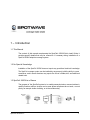
1 – Introduction
1.1 This Manual
The content of this manual complements the SpotCell® 2500Xl Quick Install Guide. It
provides specific details that may be referred to if necessary during installation of a
SpotCell 2500Xl adaptive coverage system.
1.2 No Special Knowledge
Installation of the SpotCell 2500Xl does not require any specialized technical knowledge.
The SpotCell coverage system can be installed by any person(s) with the ability to use a
screwdriver, and in some situations may require the use of a ladder, drill, and additional
related tools.
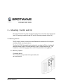
1.3 SpotCell 2500Xl at a Glance
The purpose of the SpotCell system is to enable personal wireless communications in
specific locations within a wireless service area where cell phones do not work, or work
poorly, for example inside a building, or at the cell boundary.
Spotwave Wireless Inc.
1
INTRODUCTION
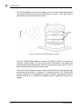
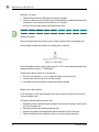
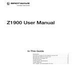
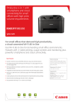
The SpotCell 2500Xl system receives signals from one or more wireless base stations
and relays the signal to areas where cell phones do not work or work poorly due to
obstructions or the remoteness of the location.
DU
CUs
Figure 1.1: SpotCell 2500Xl in-building coverage
The basic SpotCell 2500Xl system is comprised of a Donor Unit (DU), a Coverage Unit
(CU) and a power supply. The DU is the outward facing part of the system that
communicates with the base station. The DU is connected (via coaxial cable) to the CU
which provides wireless coverage to indoor areas.
The SpotCell 2500Xl adaptive system is capable of dual band and split band coverage
and provides band-selective, on-frequency, in-building coverage in the 700 MHz and
futurely in AWS bands. It uses proprietary, patented, adaptive techniques that allow a
SpotCell solution to be installed and operated without engineering intervention or
support.
2
SpotCell® 2500Xe
INTRODUCTION
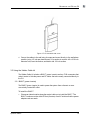
1.3.1 The Donor Unit (DU)
The DU has a 2 meter (6 foot) RG6 coaxial cable on the bottom and indicators for
showing received signal strength and system status on the back.
Figure 1.2: Bottom view of DU and cable
NOTE: In the initial version, the DU assembly is composed by a DU box and an external antenna. See Appendix B
for a picture of the assembly. The antenna will be enclosed in the box in future versions, as depicted in Figure 1.2.
Signal
strength
Status
light
Figure 1.3: Back view of DU
SpotCell® 2500Xe
3
INTRODUCTION
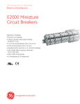
1.3.2 The Coverage Unit
The CU has two F-type coaxial ports, a power adapter port and indicators for showing
coverage level and system status.
CU cover
CU
Status
light
Coverage
level
Figure 1.4: CU with cover removed
NOTE: In the initial version, the CU assembly is composed by a DU box and an external antenna. See
Appendix C for a picture of the assembly. The antenna will be enclosed in the box in future versions, as
depicted in Figure 1.4.
Power
adapter
port
F connector
to DU
F connector
to auxiliary CU
Figure 1.5: Top view of CU and connectors
The SpotCell 2500Xl is generally format specific - CDMA/1xRTT/1xEVDO and
TDMA/GSM/GPRS/EDGE/3GPP/LTE formats. When ordering a SpotCell solution be sure to
specify the format, frequency band and sub-band. For AWS band equipment, it is helpful if
the start and stop frequencies for the operational sub-band are provided.
4
SpotCell® 2500Xe
INTRODUCTION
Alternatively, specifying your mobile phone provider (carrier) and zip/postal code on
the Spotwave website will ensure the proper system is ordered.
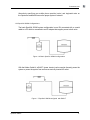
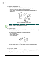
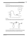
1.3.3 SpotCell 2500Xl Configurations
The basic SpotCell 2500Xl system configuration is one DU connected with a coaxial
cable to a CU which is connected to an AC adapter that supplies power to both units.
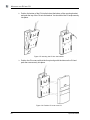
Figure 1.6: Basic SpotCell 2500Xl configuration
With the Hidden Cable kit, a BIAS-T (power inserter) can be used to discreetly power the
system or power the system from a more conveniently located AC outlet.
Figure 1.7: SpotCell 2500Xl configured with BIAS-T
SpotCell® 2500Xe
5
INTRODUCTION
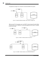
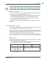
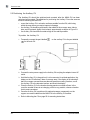
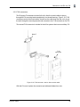
To expand the coverage area, a second CU can also be added to the system.
Figure 1.8: SpotCell 2500Xl configured with second Coverage Unit
WIth a second CU in the system, one or two BIAS-T (power inserters) from the Hidden
Cable kit can be used. The BIAS-T can be located between the DU and CU, between
the two CUs, or both.
Figure 1.9: BIAS-T installed between DU and CU
Figure 1.10: BIAS-T installed between main CU and auxiliary CU
6
SpotCell® 2500Xe
2 – Installation
2.1 Preparation
The following are general considerations and preparations that should be looked at
before installing the SpotCell 2500Xl system.
2.1.1 Signal Strength
The SpotCell 2500Xl system brings signals from an area of adequate coverage to an
area with poor or non-existent coverage. It is the DU which captures a good signal, and
the CU that provides the signal to the area with poor cell phone coverage. The DU can
be mounted inside or outside, as long as it is in an area where your cell phone works.
Generally, the better your cell phone works at the location the DU is mounted, the better
the system will perform.
2.1.2 DU Height
In fringe areas, locating the DU as high as possible will provide optimal performance.
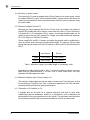
2.1.3 Avoid obstructions
General placement of the DU and CU must be in unobstructed areas. For example, the
CU should not be placed on a wall behind any type of furniture (behind items such as
metal filing cabinets would be a particularly poor location). Similarly for the DU, the front
of the unit should not be directly facing any type of metal structures, which are often
found on building rooftops.
Spotwave Wireless Inc.
7
INSTALLATION
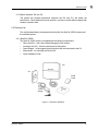
2.1.4 Proximity to power source
The indoor unit (CU) must be located within 20 feet (6 meters) of a power source, unless
the Hidden Cable kit is used. This kit includes a BIAS-T (power inserter) that allows the
system to be powered from a AC outlet located within 20 feet (6 meters) anywhere along
the coaxial cable.
2.1.5 Distance between DU and CU
Although you should separate the DU and CU as much as possible, the maximum
length of RG-6 cable that can be used to connect the two units is 115 feet (35 meters).
For greater DU to CU separation, RG-11 copper core double shielded cable can be
used to connect the two units. Using RG-11 copper core cable extends the maximum
DU to CU distance to 245 feet (75 meters).
Plenum rated RG-6 and RG-11 copper core cable may also be used for installations in
return air ceilings, floor to floor riser use and elevator shafts. The maximum Plenum cable
lengths that can be used are 100 feet (30 meters) for RG-6 and 215 feet (65 meters) for
RG-11.
non-Plenum
Plenum
RG-6
115 ft (35 m)
100 ft (30 m)
RG-11
245 ft (75m)
215 ft (65 m)
Table 1: Maximum copper core cable length for connecting units
Exceeding the cable lengths listed in Table 1 will result in reduced system coverage.
Make sure the general location of the two units is within these limits. Use only
Spotwave Wireless approved cable.
2.1.6 Distance between main CU and auxiliary CU
The maximum cable lengths that can be used to connect two CUs is the same as that
for connecting a CU and DU (see Table 1). Maximum separation of the CUs and backto-back positioning will optimize system performance.
2.1.7 Orientation of DU relative to CU
If possible face the DU and CU in opposite directions, and back to back while
maintaining maximum separation. While not a requirement, some installations will
perform better if the units are positioned in this manner. This is generally more important
for an inside mounted DU than one mounted outside on a roof or an external wall.
8
SpotCell® 2500Xe
INSTALLATION
2.1.8 Barrier between DU and CU
The greater the physical obstruction between the DU and CU, the better the
performance. Dense obstructions such as brick, concrete or metal walls are better than
wooden or plaster walls.
2.2 Packing List
This section describes the components that ship with the SpotCell 2500Xl system and
the available options.
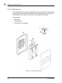
2.2.1 SpotCell 2500Xl
The SpotCell 2500Xl solution is shipped with the following components:
Donor Unit (DU) - this is the outward facing part of the system.
Coverage Unit (CU) - this is the indoor part of the system.
Power Adapter - to be plugged into an electrical outlet and connected to the CU.
Mounting Kit - for mounting the DU and CU
Quick Installation Guide
DU
CU
Install
Guide
Power
Supply
Figure 2.1: SpotCell 2500Xl kit
SpotCell® 2500Xe
9
INSTALLATION
2.2.2 SpotCell 2500Xl Auxiliary CU
The SpotCell 2500Xl Auxiliary CU kit is shipped with the following components:
Auxiliary CU - this is the second indoor part of the system.
Power Adapter - to be plugged into an electrical outlet and connected to the CU.
Mounting kit
CU
Power
Supply
Figure 2.2: SpotCell 2500Xl Auxiliary CU kit
Note: The coaxial cable needed to connect the CU to the DU can either be ordered from
Spotwave Wireless or can be supplied by the installer.
2.2.3 Hidden Cable Kit
The Hidden Cable kit makes it easier to hide the RF and power cables that are normally
connected directly to the CU.
The Hidden Cable kit is shipped with the following components:
90º F connectors (2)
BIAS-T (power inserter)
cut-in mounting ring
Figure 2.3: Hidden Cable kit
The BIAS-T (power inserter) is for indoor use only and cannot be installed outdoors.
2.2.4 DU Outdoor Install Kit
When the DU is mounted outside, the SpotCell Enterprise system requires additional
lightning protection components that are included in the DU Outdoor Installation kit
along with an extra angle mount, grounding block and U-bolts.
10
SpotCell® 2500Xe
INSTALLATION
Note: You may also need to purchase additional hardware specific to your mounting
environment (such as a non-penetrating roof mount) before you begin the installation.
2.2.5 Unpacking the Equipment
Physically inspect the box for shipping damage before unpacking the SpotCell System.
1. Remove the SpotCell 2500Xl components from the box.
2. Remove all packing material from the Donor Unit (DU) and the Coverage Unit (CU).
Save the packaging in case the system is ever stored or shipped for service.
3. Check the contents of the package to make sure you have received everything
ordered and the kits contains all the listed parts.
Check the DU and CU for shipping damage. Pay particular attention to the unit’s outer
shell casing.
2.3 Choosing a location for the DU
The DU is the outward facing unit. It is the unit that picks up the signal from and
communicates with the service providers base station network.
It may not be possible to install the DU indoors when installing the SpotCell solution in
remote areas. An effort should be made to install the DU outdoors and the DU should be
installed as high as possible when the installation is in a remote area.
Use your mobile phone handset to identify the inside location with the strongest received
signal, or the outside roof or external wall location where the strongest signal is received.
2.3.1 Positioning the DU
The following outlines the procedure for locating a DU inside a building, on a rooftop,
and on the outside surface of an external wall.
1. Remove the angle bracket from the DU and position the DU (but do not mount it) as
close to the final desired mounting location as possible.
Indoors
While not a requirement, it is highly
recommended the DU be installed 3
to 4 feet away from the glass when
facing a windowa.
Outside on a Roof
Outside on an External
Wall
The CU should not be brought outdoors if it is
raining, below freezing or above 105 Fo (40 Co).
a. Tinted windows may contain metallic particles which can degrade the radio signal more than
the adjacent exterior wall.
SpotCell® 2500Xe
11
INSTALLATION
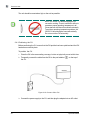
2. Temporarily connect the DU to the port labeled
on the top of the CU with
copper core coax cable.
Note: Do not directly connect CU to the 10 ft (3 m) cable already attached to the DU.
Directly connecting the CU to the DU cable may cause the system to malfunction.
Figure 2.4: Temporarily connect CU to DU
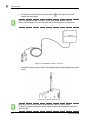
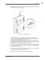
3. Connect the power supply to the CU and plug the power supply adapter into a wall
socket.
Figure 2.5: Connect power to CU
Note: Only use the power supply provided with the SpotCell 2500Xl system.
Connecting a power supply from another SpotCell system may damage the unit and
cause it to fail.
12
SpotCell® 2500Xe
INSTALLATION
4. Alignment. Hold the DU upright and pointing away from you, while:
Indoor DU
Outdoor DU On a Roof
Outdoor DU on an External
Wall
Rotating the DU left to right
with the DU facing to the
outside through the window
or exterior wall.
Rotating the DU in a
complete 360° circle.
Rotating the DU left to
right with the DU facing
away from the exterior
wall.
Exterior Wall
Window or Exterior Wall
If not in front of a window,
rotate the DU in a complete
360° circle.
Monitor the number of bars displayed on the signal strength indicator during the
rotation. The number of bars is an indication of the signal strength the DU is receiving
from the wireless base station. See DU signal level indicators: on page 35 for details
on the signal level indicator.
Signal
Strength
Status
Figure 2.6: Signal strength indicator on back of DU
SpotCell® 2500Xe
13
INSTALLATION
5. Note the direction the DU is facing when the greatest number of bars is displayed
and the Status LED is blue (no faults).
Figure 2.7: Note the DU direction with maximum number of bars and no faults
This is the direction the DU must face when it is mounted. When multiple locations
show the same greatest number of bars, mount the DU facing in the direction where
the number of bars was displayed for the longest period of time during rotation.
It is recommended that various outside roof and exterior wall locations, and locations
within the building be tested to identify the best DU location. On the upper floors of
tall buildings, it may be necessary to tilt the DU down to get the strongest signal.
6. Proceed to mounting the DU (in the location that has the highest indicated signal
level) and installing the coaxial cable (see “Mounting the DU on page 19”).
After the DU is mounted, it is recommended that you temporarily re-connect the CU
to the DU and quickly verify that the expected greatest number of bars (as found in
steps 4 and 5) is displayed.
14
SpotCell® 2500Xe
INSTALLATION
2.4 Choosing a location for the CU
The CU location is optimized, after the DU location and orientation have been optimized,
the DU has been mounted, and the copper core coaxial cable has been pulled from the
DU to the location requiring improved coverage.
Generally, the CU should be mounted in a location as far as possible behind the DU,
while being within the area where you require improved coverage and within reach of the
maximum allowed cable length (see Table 1 on page 8)
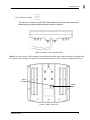
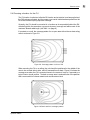
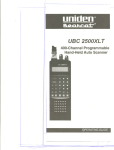
If mounted on a wall, the coverage pattern for an open area with minimum obstructing
walls is as shown in Figure 2.8.
Figure 2.8: Coverage pattern in front of CU
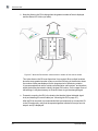
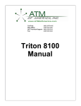
When mounting the CU on a ceiling, the unit should be positioned in the middle of the
area to be covered side-to-side, and off-centered front-to-back. Figure 2.9 shows the
coverage area when the CU is mounted closer to the center of room or if mounted on a
typical interior drywall partition. The back coverage area is reduced further if the partition
wall is constructed of a dense material such as concrete or brick.
Figure 2.9: Back and front coverage pattern
SpotCell® 2500Xe
15
INSTALLATION
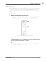
The unit should be mounted as high on the wall as possible.
Note: The 2500Xl CU has been designed for
convection cooling. There is insufficient airflow to
guarantee proper operating temperature in all
circumstances with the unit mounted horizontally.
To avoid an operating temperature problem, the
2500Xl CU should only be mounted vertically.
Do not mount the CU horizontally.
2.4.1 Positioning the CU
Before positioning the CU, ensure that the DU position has been optimized and the DU
has been mounted in place.
To position the CU
1. Place the CU in the area needing coverage, but do not physically mount at this time.
2. Temporarily connect the cable from the DU to the port labelled
on the top of
the CU.
Figure 2.10: Connect CU to DU
3. Connect the power supply to the CU, and then plug the adapter into an AC outlet.
16
SpotCell® 2500Xe
INSTALLATION
4. Hold the CU in the position it is to be mounted. Ideally the display on the back of the
CU will show 5 bars for coverage area.
Figure 2.11: Coverage display on CU
If it is not showing 5 bars for coverage area and there are alternate mounting
locations, move the CU to the alternate locations and check the display. Place the
CU in the location showing maximum number of bars.
See CU indicators on page 33 for more information on the CU Coverage Indicator.
If the number of bars is not changing, which is very possible, choose a CU mounting
location that is convenient for the area requiring coverage.
5. Once the CU is positioned for optimal coverage, permanently run the copper core
coaxial cable from the DU to the CU location. See Routing the cable and Bringing
the cable indoors on page 22.
6.
Tighten the cable connection to the CU with a wrench (a 1/4 of a turn tighter than
finger tight) to ensure moisture does not penetrate.
7. Refer to Mounting the CU on page 25 for mounting instructions.
SpotCell® 2500Xe
17
INSTALLATION
2.5 Positioning the Auxiliary CU
The Auxiliary CU should be optimized and mounted after the MAIN CU has been
optimized and mounted. The guidelines for positioning the Auxiliary CU are the same as
those for mounting the MAIN CU.
mount the Auxiliary CU in a location as far as possible from the DU, while being
within the area where you require improved coverage.
the Auxiliary CU should be positioned in the middle of the coverage area, side-toside, and off-centered slightly front-to-back, approximately as shown in Figure 2.9.
the Auxiliary CU should be mounted as high on the wall as possible.
To position the Auxiliary CU
1. Temporarily connect the port labelled
on the auxiliary CU to the port labelled
on the main CU.
Auxiliary CU
Main CU
2. Connect the extra power supply to the Auxiliary CU and plug the adapter into an AC
3.
4.
5.
6.
18
outlet.
Hold the Auxiliary CU in the position it is to be mounted. In an ideal application, the
display on the CU will show 5 bars of coverage area. If the display is not showing 5
bars for coverage area and there are alternate possible mounting locations, move
the Auxiliary CU to the alternate locations and check the display.
Place the Auxiliary CU in the location showing maximum number of bars. In the
event the number of bars is not changing, which is very possible, choose a location
that is most convenient.
Once the Auxiliary CU is positioned for optimal coverage, permanently run the
copper core coaxial cable from the MAIN CU to the Auxiliary CU location.
Refer to Mounting the CU on page 25 for mounting instructions.
SpotCell® 2500Xe
3 – Mounting the DU and CU
Mount the DU and CU only after the optimal locations for each unit has been determined
(see 2.3“Choosing a location for the DU” and 2.4“Choosing a location for the CU”).
3.1 Mounting the DU
The DU may be indoor or outdoor mounted. Based on the direction the DU will point,
consider possible mounting locations.
The SpotCell 2500Xl ships with basic hardware for mounting the DU to an inside wall
and also includes either a DU Indoor Mounting kit or an Outdoor Mounting kit. The
illustrations on the following pages show some of the possible mounting options.
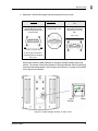
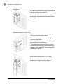
3.1.1 Mounting Options
Overhead Mount
The overhead mount provides left to right rotation, but
no up or down-tilt.
Spotwave Wireless Inc.
19
MOUNTING
THE
DU
AND
CU
Wall Mount
The wall mount configuration allows for some left to
right rotation, but no up or down tilt.
The second bracket required for this mounting
configuration is provided with the optional Outdoor
Mounting kit.
Side Surface Mount (indoor only)
The side surface mount allows for some up and
down tilt, but no left to right rotation.
There are two important concerns with this
mounting configuration:
1. This configuration cannot withstand strong winds
and should only be used indoors.
2. To keep the bracket secure, all four mounting
nuts on the back of the DU must be in place and
tightened, even if only two of the nuts are holding
the bracket to the DU.
Pipe Mount
Use U-bolts to mount the unit to a 2-in pipe.
The pipe mount allows for complete left to right
rotation with no range of up-tilt or down-tilt.
20
SpotCell® 2500Xe
MOUNTING THE DU
AND
CU
Extended Vertical Surface Mount
This configuration can be used to mount the DU from an
overhead vertical surface (such as a beam or truss) and
allows for full rotation either left to right or up and down,
depending on how the mount is fastened to the DU.
The second bracket required for this mounting
configuration is provided with the optional DU Indoor
Installation kit.
3.1.2 DU Outdoor Mounting
The mounting bracket has holes, keyhole slots, and rounded slots for 1/4-in lag bolts.
Mounting to a wood structure
1. Use the holes in mounting bracket as a template and mark the hole locations.
2. Drill 1/8-in. diameter holes approximately 2.5-in. deep.
3. Install the DU mounting bracket using at least two 1/4-in. lag bolts.
4. Fasten the DU to the mounting bracket.
Mounting to a brick or concrete structure:
1. Use holes in mounting bracket as a template and mark the hole locations.
2. Use a masonry drill bit to drill 5/16-in. diameter holes, 2-in. deep.
3. Insert masonry screw anchors so that the anchor is flush to the mounting surface.
4. Install the DU mounting bracket using at least two 1/4" lag bolts.
5. Fasten the DU to the mounting bracket.
SpotCell® 2500Xe
21
MOUNTING
THE
DU
AND
CU
Mounting to a pipe:
1. Fasten the bracket to the DU before mounting to the pipe.
2. Feed the u-bolts (from the Outdoor Install kit) through the rounded rectangular slots
as shown in “Use U-bolts to mount the unit to a 2-in pipe.”.
3. Aim the DU at the signal source and tighten the u-bolts.
Note: DO NOT use cable ties to mount the DU.
Routing the cable
When routing the cable on a roof be sure to locate it where it will not be tripped over.
Use tie-wraps to attach the cable to an existing pipe or cable run.
Figure 3.1: Cable Strap
Secure the cable to wood or siding walls using #6 x 1.5-in. wood screws and cable loop
straps as shown in Figure 3.1:“Cable Strap”.
To attach the cable to a brick or concrete wall:
1. Drill a 3/16-in. diameter x 1-1/4 in. deep hole using a masonry drill bit.
2. Insert the anchor flush with the mounting surface.
3. Use cable clamps and screws to attach the cable to the wall.
Bringing the cable indoors
If it is necessary to run a cable through a wall, use a masonry or wood drill bit to drill a
3/4-inch diameter hole.
To bring the cable through an exterior wall:
1. Depending on the material the wall is made of use a wood or masonry drill bit to drill
a 3/4-in. diameter hole.
2. Pass the connector and cable through the wall.
3. Use the putty/sealant (provided with Outdoor Installation kit) to fill the hole.
4. Fashion a drip loop in the cable if the hole is not next to the ground block.
22
SpotCell® 2500Xe
MOUNTING THE DU
AND
CU
Grounding the DU
When the DU is installed outside, electrical (or building) code calls for the outer
conductor of the coaxial cable to be grounded at or near the point of entrance of the
cable into the building. A ground-block is provided with the Outdoor Installation kit.
DU
CU
Ground block
Figure 3.2: Ground coaxial cable with ground block
Drip Loops
While securing the cable outside, ensure that a drip loop is fashioned on both sides of
the ground block and fasten a tie wrap around the loop to keep the loop secured.
wall
penetration
to CU
to DU
Figure 3.3: Drip loops on both sides of ground block
If where the cable enters the building is not next to the ground block, then another drip
loop will also have to fashioned at this point. The drip loop prevents water from collecting
around the cable where it attaches to the block or where it enters the building.
SpotCell® 2500Xe
23
MOUNTING
THE
DU
AND
CU
Ideally the ground block should be bonded to the roof ground network, a metal cold
water pipe, structural steel, or metal electrical conduit. Use #10-AWG solid-copper wire
(minimum). Green insulation is preferred. Alternatively uninsulated #8-AWG aluminum
may be permitted. Be sure to check national and local code requirements.
Connect the ground wire to the cold water pipe or alternative using an appropriate
crimp-on ring or lug connector. Ground conductor and termination hardware are not
supplied.
Warning! Failure to properly ground the DU will leave the unit and building vulnerable to
damage from lightning strikes. Check local building and electrical code requirements and
comply with both local and national regulations.
Ideally the DU ground wire should be bonded to the roof ground network. For roofs
without such a network use a metal cold water pipe, structural steel, or metal conduit.
3.1.3 DU indoor mounting
To mount the DU indoors:
1. Use the mounting bracket as a template and mark the hole locations.
2. If the mounting is in a solid wood surface, or a stud covered by drywall, drill a 5/32
inch diameter hole. Mount the unit with 2 inch wood screws.
or
If the mounting is in drywall, drill a ¼ diameter hole and insert an anchor. Mount the
unit with 1/2 inch pan head screws.
3. Attach cables to the wall using tie wraps and mount directly to the wall where
possible (using 1/2 inch pan head screws). If an anchor is required drill a 3/16 inch
diameter hole, insert the anchor, and fasten with 1/2 inch pan head screws.
24
SpotCell® 2500Xe
MOUNTING THE DU
AND
CU
3.2 Mounting the CU
Find a suitable location to mount the unit that will provide good signal coverage. Refer to
section 2.4“Choosing a location for the CU”. The SpotCell 2500Xl CU is surface
mounted using the provided bracket and can be either mounted to a wall or hung from a
ceiling.
To mount the CU
1. Fasten the mounting bracket to the wall or ceiling.
If mounting on a solid wood surface, or stud covered by drywall, drill a 1/8th
inch diameter hole and then fasten the mounting bracket with #6 x 1.5” screws.
Figure 3.4: CU bracket fastened with screws
or
If mounting to drywall, drill a ¼ inch diameter hole, insert the screw anchors, and
then fasten the mounting bracket with 1/2” screws.
or
If mounting to a ceiling or t-bar, use the bracket and clips that are supplied with
the optional SpotCell Ceiling Mount Install kit.
SpotCell® 2500Xe
25
MOUNTING
THE
DU
AND
CU
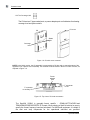
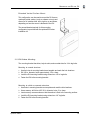
2. Position the bottom of the CU into the hole at the bottom of the mounting bracket
and push the top of the CU onto the bracket. You should feel the CU snap securely
into place.
Figure 3.5: Inserting the CU into the bracket
3. Position the CU cover such that the four pins align with the holes on the CU and
push the cover securely into place.
Figure 3.6: Position CU cover over CU
26
SpotCell® 2500Xe
MOUNTING
THE
DU
AND
CU
Figure 3.7: CU mounted with cover
4.
Secure the cables to the wall using tie wraps and mount directly to the wall where
possible (using 1/2 inch pan head screws). If an anchor is required drill a 3/16 inch
diameter hole, insert the anchor, and fasten with 1/2 inch screws.
3.3 Using the Hidden Cable kit
The Hidden Cable kit includes a BIAS-T (power inserter) and two F-90 connectors that
make it easier to hide the power and RF cables that are normally connected directly to
the CU.
3.3.1 BIAS-T (power inserter)
The BIAS-T (power inserter) is used to power the system from a discreet or more
conveniently located AC outlet.
To install the BIAS-T
1. Choose an indoor location along the coaxial cable run to install the BIAS-T. The
BIAS-T location must be within 20 feet (6 meters) of an AC outlet so that the power
adapter cord can reach.
SpotCell® 2500Xe
27
MOUNTING
THE
DU
AND
CU
2. If the AC adapter can reach the end of the 10 ft (3m) cable attached to the DU then
simply attach the BIAS-T to the DU cable and then the cable coming from the CU.
Figure 3.8: BIAS-T inserted near DU
or
If the DU is too far from the AC outlet, cut the coaxial cable at the chosen location,
properly terminate both ends with Spotwave approved connectors, and attach the
the BIAS to the two new connectors.
Figure 3.9: BIAS-T inserted far from DU
3. Connect the power supply to the BIAS-T and then plug the adapter into an AC
outlet.
28
SpotCell® 2500Xe
MOUNTING THE DU
AND
CU
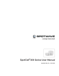
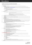
3.3.2 F-90 connectors
The 90 degree F connectors included in the kit, allow the coaxial cables to be run
through the CU mounting bracket and directly into the wall opening. Figure 3.10:“F-90
connector used to hide coaxial cable” shows how the cable runs from the cut-in ring in
the wall, through the mounting bracket and connects to the F-90 connector on the CU.
The second F-90 connector is included in the kit for systems that use an auxialliary CU.
BIAS-T
F-90
connector
Figure 3.10: F-90 connector used to hide coaxial cable
With the CU cover in place, the connector and cable are hidden from view.
SpotCell® 2500Xe
29
MOUNTING
THE
DU
AND
CU
3.4 CU Ceiling Mount kit
The CU Ceiling Mount kit is used to hang the CU directly from a ceiling. This kit replaces
the standard CU mounting bracket with metal bracket that attaches to the bacl of the
CU and fastens either directly to the ceiling or to the supplied t-bar hanger.
The kit includes:
1. Back cover
2. Ceiling bracket
3. Twist fastener (t-bar hanger)
Figure 3.11: CU Ceiling Mount kit
30
SpotCell® 2500Xe
4 – Trouble-Shooting
1. Status: The LED on the back of the DU and CU display information regarding the
SpotCell system during operation.
Action: A red LED indicates a fault condition, a yellow LED indicates an overdrive
condition, and blue indicates power on, no faults. A green LED on the CU indicates
reduced coverage due to a signal isolation condition.
2. Status: The LED on the DU is not illuminating.
Action: Ensure the following:
The cable from the DU is connected to the CU port labelled
.
The power supply is connected to the CU or BIAS-T (power inserter).
The power supply is plugged into an electrical outlet.
If the LED is still not illuminating, contact technical support.
3. Status: My cell phone does not work around the location I would like to install the
SpotCell DU.
Action: Try positioning the DU externally as high as possible.
4. Status: The DU and CU are installed properly, but your cell phone only works in
close proximity to the CU.
Action: There are three factors that may be affecting coverage as described below:
Visually inspect the area around the CU. Ensure that there are not any large
metallic objects directly between the CU and the area where cell phone coverage
is not adequate. Remount the CU so that it is out in the open.
If the signal the DU is receiving is very weak (although still strong enough to allow
operation), the area around the CU within which a cell phone can function will be
relatively small. An effort can be made to improve system performance by raising
or otherwise repositioning the DU in an effort to obtain a stronger signal.
check with your vendor that your SpotCell product is compatible with your cell
phone service.
Spotwave Wireless Inc.
31
TROUBLE-SHOOTING
5. Status: The coverage area around the CU suddenly shrinks after a long period of
reliable operation.
Action: This is most likely due to man made environmental influences such as a
large building being erected somewhere in between the DU and the location the DU
is receiving a signal from. Repeating the install procedure with the DU in its current
position may improve system performance (i.e. re-aligning it in the direction that
provides greater signal strength). If this does not help, the DU may have to be
physically repositioned at a different location; going through the install procedure
starting at Choosing a location for the DU on page 11, is necessary at this point.
6. Information: Remote installation SpotCell characteristics.
In order for the SpotCell system to function, there are two basic parameters that
must be met. The DU must receive a minimum amount of wireless signal, and a
physical environment that blocks wireless signals must be in between the DU and
CU (i.e. a wall).
If the DU is not receiving an adequate signal, the system will not work, or, it will work
but provide a very limited area around the CU in which a cell phone will function. In
this instance, it may be possible that only one cell phone will be capable of using the
system at a time. This is typical of applications that are on the fringe, or outside of a
wireless providers advertised coverage area. Improved performance will typically
only be attained by moving the DU to a higher location.
7. Information: Building installations that do not provide for brick, concrete, metal,
or other dense material between the DU and CU.
Action: In this situation it is possible that the signal emitted by the DU will be received
by the CU. This will result in the system lowering the power of the signal it is emitting;
and therefore the area around the CU in which a cell phone will function will become
smaller. To improve performance in this scenario, it is important to:
Maximize the height of the DU
Separate the DU and CU horizontally as much as possible (within the maximum
cable limits as shown in Table 1, Maximum copper core cable length for
connecting units on page 8).
Mount the DU and CU in a back-to-back manner.
32
SpotCell® 2500Xe
Appendix A – 2500Xl System Specifications
Note: Spotwave Wireless has the right to change specifications without notice.
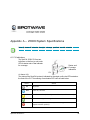
A.1 CU indicators
The SpotCell 2500Xl CU has two
indicators on the front, a mult-color
LED for status and a 5 bar indicator
for coverage.
Status and
Coverage
indicators
CU
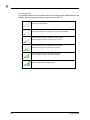
CU Status LED
The status of the SpotCell system is indicated by the single multi-color LED located on
the front of the CU. The meaning of each status LED color is listed below.
Color
Spotwave Wireless Inc.
Status
Off
No power.
Blue
Power on, no faults.
Yellow
Overdrive condition (either adjacent or in-band, not discriminated).
Green
Reduced coverage due to signal isolation condition.
Red
Fault condition (could indicate a system fault, upgrade failure, or
expired activation period).
33
CU Coverage bars
The graduated bars on the CU indicate the level of coverage which is determined by the
isolation required to generate optimum output power at the CU.
0 bars indicate either a >20dB back-off or that the power is off.
System will not operate.
1 bar indicates a back-off between 17 and 20dB.
Very small coverage area. Operation may be intermittent.
2 bars indicate a back-off between 13 and 16dB.
Small coverage area that is likely to vary in size.
3 bars indicate a back-off between 9 and 12dB.
Reduced coverage area that may vary in size.
4 bars indicate a back-off between 5 and 8dB.
Good coverage area that will remain stable.
5 bars indicates 0 to 4 dB back-off (coverage maximized at 0 dB).
Optimum and stable coverage area.
34
SpotCell 2500Xe
A.2 DU signal level indicators:
The SpotCell 2500Xl DU has two indicators on the back, a mult-color LED for status
and a 5 bar indicator for received signal level.
Note: Both indicators automatically shut off after the system has been powered for 20
minutes. To re-activate the display, either cycle the system power off/on or disconnect
and then re-connect the DU’s coaxial cable.
DU Status LED
The status of the SpotCell system is indicated by the single multi-color LED located on
the back of the DU. The meaning of each status LED color is listed below.
Color
SpotCell 2500Xe
Status
Off
No power.
Blue
Power on, no faults.
Yellow
Overdrive condition (either adjacent or in-band, not discriminated).
Red
Fault condition (could indicate a system fault, upgrade failure, or
expired activation period).
35
DU Signal Level Indicator
The graduated bars on the back of the DU indicate the signal level received by the DU
0 bars indicate the received signal is too low (less than -95 dBm)
or that the power is off.
1 bar indicates the received signal level from the base station is
very low (-85 to -95 dBm). Operation may be intermittent.
2 bars indicate the received signal is just within operational range
(between -85 and -75 dBm).
3 bars indicate the received signal is between -75 and -65 dBm.
4 bars indicate the received signal is between -65 and -55 dBm.
5 bars indicate the received signal is at the highest level (greater or
equal to -55 dBm).
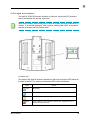
A.3 Antenna Specifications:
700 MHz
DU Antenna
CU Antenna
11 dBi
2 dBi
TBD
TBD
Elevation Beamwidth - typical (dg)
38º
90º
TBD
TBD
Azimuth Beamwidth - typical (dg)
68º
NA
TBD
TBD
>20 dB
0 dB
TBD
TBD
Gain (dBi)
Front-to-Back Ratio (dB)
Polarization
36
AWS
DU Antenna
CU Antenna
Vertical
SpotCell 2500Xe
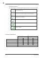
A.4 Architecture (Dual Band 7 00 MHz/AWS Coverage System)
Frequency Bands
(see NOTE below)
AWS Uplink: 1 7 4 5 -1755 MHz
Downlink: 2 1 4 5 -2155 MHz
700 MHz Uplink: 7 7 7 -787 MHz
Downlink: 7 4 6 -756 MHz
Sub-Bands
Operator sub-bands: Operator Specific
Primary sub-band: 7 0 0 M H z (Upper C) AWS (None)
Secondary AWS (split-band) options: N o n e
Formats Supported
700 MHz (3GPP / LTE)
AW S (TBD)
Typical Coverage Area
25,000 sq. ft (2,300 m2)
Open Coverage Area
50,000 sq. ft (4,600 m2)
System Gain
(includes antenna)
Uplink: 0 to +70 +/- 2 dB maximum
Downlink: 0 to +70 +/- 2 dB maximum
System Stability Margin
> 10 dB (fully adaptive)
Downlink Operating Range
-95 to - 45 dBm (receive isotropic power)
Maximum Input Level
Uplink: -10 dBm
Downlink: -45 dBm
(receive isotropic power)
Output Level -EIRP
Uplink: +28 dBm +/-2 dB EIRP maximum
Downlink: +5 dBm +/- 2 dB EIRP maximum
Third Order Intercept
(EIRP, radiated)
AWS Uplink: TBD
Downlink: TBD
700 MHz Uplink: +53 dBm
Downlink: +27 dBm
Power Consumption
< 45 W
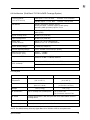
A.4.1 Physical
Operating
Temperature
Size
Weight
DONOR UNIT
COVERAGE UNIT
-40° to 130 F°
(-40° to +55° C)
32° to +104° F
(0° to +40° C)
14 x 12.5 x 3 in.
(36 x 31.5 x 8 cm)
6 x 9.25 x 1.75 in.
(15.5 x 23.5 x 4.75 cm)
12 lb. (5.5 kg)
2 lb. (1 kg)
RF Connectors
Type F: Coverage Port (weatherproof)
Type F: Donor Port
Type F: Extension Antenna Port
RF Cable
Coverage specification is met with up to 25m RG-6 cable between Donor &
Coverage Units
Optional RF Cable
Plenum rated or RG-11 also available
Power Supply
Universal power adapter (90 - 260 VAC, 47 -63 Hz)
NOTE: The 2500Xl initially offers only Upper Band C for 700 MHz. AWS is not implemented.
SpotCell 2500Xe
37
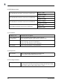
A.4.2 BW Measurements
Uplink = 6 MHz
700 MHz Band A bandwidth measurement at 20dB down
Downlink = 6 MHz
Uplink = 6 MHz
700 MHz Band B bandwidth measurement at 20dB down
Downlink = 6 MHz
Uplink = 10 MHz
700 MHz Band C bandwidth measurement at 20dB down
Downlink = 10 MHz
Uplink = TBD
AWS 15MHz bandwidth measurement at 20dB down
Downlink = TBD
A.4.3 Installation
Installation Time
Less than one hour typical
Donor (outward facing)
Unit Alignment
No prior knowledge of base station location required.
Built in alignment algorithm (LED Indicator on Donor Unit).
Test Equipment
None required.
No RF knowledge required for installation.
Easy-to-read LED indicators guide installation
User Controls
None, setup and operation is fully automatic.
A.4.4 Diagnostics
User Interface
Built-in LED coverage area display on Coverage Unit
Built-in signal strength display on Donor Unit
A.4.5 Coverage Extension
Coverage Area
38
Second Coverage Unit provides an additional 25,000 sq. ft (2,300 m2)
coverage when connected to the primary Coverage Unit with up to 164 ft
(50m) of RG-6 cable or 328 ft (100m) of RG-11 cable.
SpotCell 2500Xe
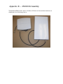
Appendix B – 2500Xl DU Assembly
The SpotCell 2500Xl initial version includes a DU box and an external antenna, as
displayed in the following picture:
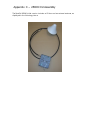
Appendix C – 2500Xl CU Assembly
The SpotCell 2500Xl initial version includes a CU box and an external antenna, as
displayed in the following picture:
Notes
1. This equipment has been tested and found to comply with the limits for a
Class A digital device, pursuant to part 15 of the FCC Rules. These limits
are designed to provide reasonable protection against harmful interference
when the equipment is operated in a commercial environment. This
equipment generates, uses, and can radiate radio frequency energy and, if
not installed and used in accordance with the instruction manual, may
cause harmful interference to radio communications. Operation of this
equipment in a residential area is likely to cause harmful interference in
which case the user will be required to correct the interference at his own
expense.
2. This device complies with part 15 of the FCC Rules. Operation is subject to
the following two conditions: (1) This device may not cause harmful
interference, and (2) this device must accept any interference received,
including interference that may cause undesired operation.
3. Changes/modifications not approved by the responsible party could void the
user’s authority to operate the equipment.
Notes
SPOTWAVE
coverage made simple
www.spotwave.com
Spotwave Wireless Ltd. 500 Van Buren Street, Kemptville, ON KOG 1 JO Canada
© 2011 Spotwave Wireless Ltd. All rights reserved. Printed in Canada
Spotwave and SpotCell are trademarks of Spotwave Wireless Ltd. Patents pending.
780-00043-04-02