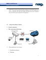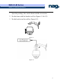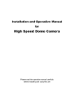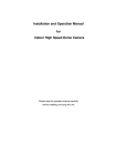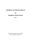
1
SNR-CI-M Series
Network IP Cameras User Manual
NETWORK HIGHSPEED DOME
MANUAL
Please read the operation manual carefully
before installing and using this unit
SNR-CI-M Series
Network IP Cameras User Manual
SAFETY PRECAUTIONS
C AU TI O N
RISK OF ELECTRIC
SHOCK. DO NOT OPEN!
C A U T I ON :
TO REDUCE THE RISK OF ELECTRICAL SHOCK, DO DOT
OPEN COVERS. NO USER SERVICEABLE PARTS INSIDE.
REFER SERVICING TO QUALIFIED SERVICE PERSONNEL
The lighting flash with a arrowhead symbol, in an
equilateral triangle, is intended to alert the user.
There is uninsulated “dangerous voltage” presence
near by the product's enclosure which may be risk of
to persons .
The exclamation point within an equilateral
triangle is intended to alert the user to reference
o f t he i mp ort ant op era tin g and m ai nt ena nce
(servicing ) instructions .
2
SNR-CI-M Series
Network IP Cameras User Manual
THE PRODUCT CODE MARKED ON THE BOTTOM COVER. PLEASE
FILL THE CODE IN THE FOLLOWING BLANK. PLEASE SAVING
THIS SPECIFICATION CAREFULLY, SO THAT CHECKING.
MODEL:________________________
PRODUCT CODE:________________________
3
SNR-CI-M Series
Network IP Cameras User Manual
INDEX
I. Important Safeguards.................................................... 5
II. Description of Functions................................................ 6
III. Setup of the Menu of the Dome Camera.................................. 7
IV. Setup of the Dome Camera.............................................. 11
V. The Installation of the System......................................... 11
VI. Technical data table.................................................. 14
VII. Troubleshooting (Software part in software manual) .................. 15
4
SNR-CI-M Series
Network IP Cameras User Manual
I. Important Safeguards
1. All the safety and operating instructions should be read before the units is operated.
2. This unit should be operated only from the type of power source indicated on the marking
label. If you are not sure of the type of power supply you plan to use, consult your appliance
dealer or local power company. For units intended to operate from battery power or other
sources, refer to operating instructions.
3. During the course of transportation, storage and installation, the product should be avoided
from incorrect operations such as heavy pressing, strong vibration etc., which can cause
damage of product as there are sophisticated optical and electronic devices inside the
machine.
4. Do not attempt to disassemble the camera. In order to prevent electric shock, do
not remove screws or covers. There are no user-serviceable parts inside.
5.
Always follow all electrical standards for safety when it is in operation. Adopt the
particular power supply which is provided with the unit. RS-485 and video signal
should keep enough distance with high voltage equipments and cables when they
are in transmission. Precautions for anti-lightning and anti-surging should be
taken if necessary.
6. Do not operate it in case temperature, humidity and power supply are beyond the
limited stipulations.
7. Do not let the camera aim at the sun or the object with extreme light whatsoever it
is switched on or not. Do not let the camera aim at or monitor bright and standstill
object for a long time.
8. Do not use aggressive detergent to clean the main body of the camera. Wipe dirt
with dry cloth. If needed, mild detergent can be used suitably.
9. Operate the intelligent speed dome camera with great care to avoid shock or
vibration. It operate incorrectly, the Speed Dome could be damaged.
10.Do not place this unit on an unstable stand, tripod,
bracket, or mount. The unit may fall, causing
serious injury to a person and serious damage to the
unit. Use only with a stand, tripod, bracket, or
mount recommended by the manufacturer or sold
with the product. Any mounting of the unit should
follow the manufacturer’s instructions and should
use mounting accessory recommended by
manufacturer.
11.If necessary, use a commercial lens cleaning paper to clear the lens windows.
Gently wipe the lens window until clean.
5
SNR-CI-M Series
Network IP Cameras User Manual
II. Description of Functions
The network dome camera is a high-tech surveillance product, which integrated
network transmission, high definition color camera, P/T, decoder, CPU and memory
chip. Fast installation construction, more easy to install, enhanced the reliability of the
system. Also it is easy to service.
The network dome camera achieves the long-distance control by network, and it
is suitable for various situation.
1.
Integrated Speed-Variable PAN/TILT
a. Turning 360ºhorizontally and continuously with unlimited positions and an
adjustable speed from 0.2 - 300 rad/s; turning 0 - 90º vertically with a speed up to
120 rad/s.
b. Running stably at low speed with super lower noise. Pictures have no
shaking.
c. Automatic 180º flip and panoramic monitoring without blind point, the
location precision up to ±0.1°.
2. High Intelligent Degree
a. As much as 128 preset positions can be preset with powerless memory.
b. The camera can scan horizontally between two points and scan speed can be
modified. The positions of linear scan are optional and the dome camera can
scan the range larger or smaller than 180° between any two points with
adjustable speed;
c. Six sets of programmable tour locus with 16 position each set. The running
speed and the detention time are adjustable respectively;
d. The dome camera can simulate the PTZ route operated by you in 40 seconds
by the self-learning function of the locus with powerless memory;
e. Character Overlapping. The humane structure of the menu makes all setups
and programming of the dome camera more convenient and easy.
f. Proportional pan function. The speed dome will depend on the amount of
zoom. At telephoto zoom settings, the pan and tilt speeds will be slower for a
given amount of joystick deflection than at wide zoom settings. This keeps
the image from moving too fast on the monitor when there is a large amount
of zoom. This slowing does not happen when going to a preset, but does
occur in turbo mode when high zoom is selected. The minimum pan and tilt
speeds are 0.1 degree per second at full zoom.
g. The Integrated Multi-Protocol. Multiple communication protocols are
integrated inside the dome camera with selectable baud rate from 2400 bps to
9200 bps.
3.
Functions of the Camera (icons can be displayed on the screen when the option
6
SNR-CI-M Series
Network IP Cameras User Manual
DISPLAY of the camera is ON)
a. Description of the Focus Control Mode: the user can adjust the focus of the
camera manually. When the camera is on near focus, the icon
appears on
appears while on the far
the screen; when on the nearest state, the icon
focus, the icon
appears.
b. Description of Backlight Compensation: when the object to be shot is dark
and looks dim, the user can open the backlight compensation according to
actual need and the icon
appears on the screen.
c. Description of White Balance: when the image has color distort on the
screen, the user can set different modes by orders. There are 6modes for
options: ① Indoor Mode
② Outdoor Mode
③ Touch Mode
④Automatic Trace of White Balance ATW ⑤ Manual WB-MAN
⑥
Automatic Mode.
d. Description of ZOOM Control: user can “pull near” or “push far” the lens
according to actual conditions, and the symbol
appears on
the screen in which the front part means optical multiplication while the rear
part means digital multiplication.
e. Description of Electronic Shutter: it is fixed on 1/50 sec after initialization
when the camera is switched on, and the digital 50 appears on the screen.
f. Setup of Image Effect: the camera works on OFF state under normal
condition and no image effect symbol appears on the screen. When “B&W”
appears on the screen, it means the camera is on black and white state.
g. AE Mode: setup of Manual/Automatic.
h. Zero Illuminance: It is used only when the external brightness is extremely
low. Normally the camera works on the automatic state. In case the external
brightness is lower than 1Lux, the camera can be switch to the Zero
Illuminance state automatically and icon
appears on the screen. You
can also set the Zero Illuminance state manually.
III. Setup of the Menu of the Dome Camera
1.
Basic Operation of the Menu(
(Encl: Software manual)
manual)
1.1 The main menu will be opened, when Call Preset 64 or Call Preset 1 twice in 4 minutes.
1.2 When the menu is displayed on the screen, operate “UP”, “DOWN” to move the
cursor to the option to be set, operate “LEFT”, “RIGHT” to modify the content
or the order to enter this option.
1.3 Keep the joystick in one direction for over 1 second to speed up operation.
1.4 All setups on the menu couldn’t be lost even power failure happens.
1.5 Special utilizations can be seen on the descriptions of functions of the menu in
detail.
2. Setup of the Menu
2.1 MAIN MENU
7
SNR-CI-M Series
Network IP Cameras User Manual
2.1.1
DISPLAY SETUP: to enter the submenu of display of the screen by which
ID display, title display of preset point and display
of camera screen can be set.
2.1.2 CAMERA SETUP: to enter the submenu of setup
of normal data of camera.
2.1.3 CONTROL SETUP: to enter the submenu of
setup of control data over the dome camera.
2.1.4 CAMERA MASK SET: to enter the submenu of
setup of mask function of camera.
2.1.5 PROGRAM: to enter the setup of enhanced
function of dome camera.
2.1.6 PAL CAMERA: PAL/NTSC switching to suit the
camera.
2.1.7 CAM DEFAULT SET: to reset default setup of camera.
2.1.8 DOME RESET: to reset the dome camera.
2.1.9 EXIT: to quit the main menu.
2.2 DISPLAY SETUP
2.2.1 ID DISPLAY: when it is set at ON, address
of dome camera appears on the screen such as
“CAM 001”. The default setting is ON.
2.2.2 ID POS: to set the display position of
address on one of following corners: TOP-L,
TOP-R, BOTT-R and BOTT-L.
2.2.3 TITLE DIS: when it is set at ON, the title of
preset point appears on the left of screen such
as "NO.001 ABCDEFGH” when the preset
point is called. The modification of title of preset point is set on PROGRAM
option.
2.2.4 TITLE POS: to set the display position of title of preset point from Line 1 to
Line 10. Line 1 is at the top of screen.
2.2.5 CAM DISPLAY: when it is set at ON, the camera screen will be opened.
2.2.6 RETURN: to return to MAIN MENU.
2.3
CAMERA SETUP
2.3.1 SLOW SHUTTER: frame accumulation with
two options Manual/Automatic. When camera
screen is opened under automatic state, ASS
displays on screen.
2.3.2 BACK LIGHT:
backlight compensation
ON/OFF.
2.3.3 ICR SHOT: low shooting,ON/AUTO
2.3.4 IRIS: setup of automatic iris AUTO/MANU.
2.3.5 D-ZOOM: setup of digital zooming ON/OFF.
2.3.6 FOCUS: setup of automatic focusing AUTO/ MANU.
2.3.7 WB SET: setup of white balance. ATW / INDOOR / OUTDOOR / ONEPUSH
/ AUTO / MANU
2.3.8 MENU OF CAM: blank
2.3.9 RETURN: return to MAIN MENU.
2.4 CONTROL SETUP
8
SNR-CI-M Series
Network IP Cameras User Manual
2.4.1
2.4.2
2.4.3
AUTO FLIP: 180° automatic flip of dome camera ON/OFF.
ALARM: blank.
PRESET PIC: if image is followed when calling preset point or making tour.
FREEZE – when switching scene to freeze image and to recover
otherwise; MOVE – when switching scene no image frozen.
2.4.4 HOME OPTION:
enter the submenu of
automatic home function.
2.4.4.1 AUTO HOME: when it is set at ON, home
function is available, namely, the dome
camera will return HOME if user has no
action in a period of time. The dome camera
shall not return HOME if it is on tour state. If
no HOME is needed when the dome camera is stopped, set the option at
OFF.
2.4.4.2 HOME POS: HOME means return home. For example to set one scene as
HOME, call the scene first and set it as preset point, then call out the menu
to enter into this submenu, change figures after HOME POS into 5. If
automatic HOME function is needed, do not forget to set AUTO HOME at
ON. The preset points of HOME POS are from 1 to 63 and 65 to 128.
2.4.4.3 DWELL TIME: to set the time of automatic HOME, which means the
camera shall return HOME if it is not controlled in a period of time which
can be from 1 to 99 minutes.
2.4.4.4 RETURN: return to the menu one level higher.
2.4.5 RETURN: return to MAIN MENU.
2.5 CAMERA MASK SET
2.5.1 MASK PRIVACY: blank.
2.5.2 MASK SHADE: blank.
2.5.3 MASK REGION: blank.
2.5.4 RETURN: return to Main Menu.
2.6 PROGRAM Options
2.6.1 AUTO PAN START POS: To set start position of auto scan between two
points. To move the dome camera by joystick after entering and to return by
CLOSE button.
2.6.2 AUTO PAN END POS: To set end position of auto scan between two points.
To move the holder by joystick after entering and to return by CLOSE button.
2.6.3 RUN AUTO PAN: Auto scan function between two points. First of all, you
must set the start position and the end position of auto scan. If the start
position is just the end position, it means 360° scan. The speed of auto scan
has six grades: FAST / NORMAL / SLOW / -FAST / -NORMAL / -SLOW in
which the first three grades are scan less than
180° while the later three grades larger than
180°. Adjust speed by PAN LEFT/PAN
RIGHT, and operate and exit by OPEN button.
The start position and the end position of auto
scan are set by options 1 and 2 in this
submenu.
2.6.4 SET TITLE: to edit titles of preset position.
Only previous 63 preset points have their titles.
Select no. of preset point by PAN LEFT/PAN
9
SNR-CI-M Series
Network IP Cameras User Manual
RIGHT, enter into edit by OPEN button and exit edit by CLOSE button.
Operations under edit state can be seen later.
2.6.5 SET PATROL: to edit data for multi-points patrol. Select no. of patrol by PAN
LEFT/PAN RIGHT, enter into edit by OPEN button and exit edit by CLOSE
button. Operations under edit state can be seen later.
2.6.6 RUN PATROL: to run multi-points patrol function. Select no. of patrol by
PAN LEFT/PAN RIGHT, run and exit by OPEN button.
2.6.7 RECORD PATTERN: This pattern can consist of any standard pan and tilt or
lens command. Presets, flip, digital zoom, proportional pan, and turbo are not
allowed in a pattern. The pattern length is 40 seconds in maximum. To return
when 40 seconds expire or by push CLOSE button.
2.6.8 RUN PATTERN: to self-learn loci of tour. To exit the menu after running or
to stop running by joystick.
2.6.9 RETURN: return to Main Menu.
3. Appendix to the Menu
3.1 Operation of Edit State of Multi-Points Patrol. When entering into edit state
the screen displays as follows:
NO – serial No. of patrol position
POS – No. of preset position
SP – leaving speed
TM – dwelling time
After entering into edit area, screen shows as
follows:
Edit Area, data of 2 patrol position appears
on one line.
SEQ:01
– It means the set No.1
patrol
CLOSE:EXIT – Push CLOSE to exit edit
state
3.2
Both top and bottom lines display prompt and information of each patrol is
displayed on the middle of the screen. Data of 2 Patrol points appears on one
line. Move cursor by PAN LEFT/RIGHT and modify data by TILT UP/DOWN.
Press buttons for one second to speed up operation. Press CLOSE button to exit
edit state and store modifications. The program will search the position of the
first “---” of POS, store dada before it and regard data after it as invalid. In
above figure, the program stores previous four points with settable range from 1
to 63 and from 65 to 128. When “---” of POS appears, the tour range is ended.
The settable range of SP is from 0 to 8 (0 and 1 are the same with fastest speed
while 8 has the lowest speed). The settable range of TM is from 0 to 99 seconds.
Operation of Title of Preset Point in Edit State. When entering into edit state
the screen displays as follows:
In the figure we find the preset point is No.1
with title of “NO TITLE”. Move cursor by PAN
LEFT/RIGHT and modify data by TILT
UP/DOWN. Press buttons for one second to
10
SNR-CI-M Series
Network IP Cameras User Manual
speed up operation. Press CLOSE button to exit edit state and store
modifications. The title of preset point has 8 characters in maximum such as 0-9,
A-Z, +, - and space. Note: the first character should be 0-9 or A-Z, otherwise it
means to delete the title of the preset point, and when preset point is adjusted,
only “NO.XXX” spears without title to be displayed.
IV. Setup of the Dome Camera
1. System connection
1)
The system map of the dome
V. The Installation of the System
1、Installation manner
a) Hanging
11
SNR-CI-M Series
Network IP Cameras User Manual
1.
Open the packing, take out the dome and the accessories.
2. Fix the dome with the bracket well (as Figure 4-1 & 4-2).
3. Fix the bracket on the wall (as Figure 4-3).
Figure 4-1
8
Figure 4-2
12
SNR-CI-M Series
Network IP Cameras User Manual
Figure 4-3
b) Ceiling
Φ7
Figure 5
Figure 6 Dome down lead
Notice:
13
SNR-CI-M Series
Network IP Cameras User Manual
The lines of the POWER SUPPLY and the LAN is the default, other down-leads
will be made by client’s order.
4.
To Ensure a Smooth and Successful Installation, You Should:
1、Have electrical work to comply with latest national electrical code, national
fire code, and all applicable local codes and ordinances.
2、Coordinate with other trades to avoid interference.
3、Verify existing conditions on the site and coordinate with owner side to ensure
necessary utilities available.
4、Copy all related plans, specifications, shop drawings and attachments to
schedule and coordinate related work.
5、 Thoroughly review the project to ensure that all jobs should meet or exceed
the above requirements. Contact with the CCTV Project Coordinator to draw
attention in case alleged discrepancies occur.
VI. Technical data table
Pixels
1/4″Color CCD
752 H×582 V(440000 pixels)PAL
In-Phase System
In-Phase Inside
Video Output
1.0 Vp-p/75Ω
White Balance
Auto / Manual
Specificatio
Power Supply
AC 24V±10% 1.25A (with fan/heater)
ns
Power Consumption
Image Inductor
Weight
Camera
Function
Lens
Parameter
Dome
Function
30 VA (with fan/heater)
15 VA (indoor)
2 Kg
Opposite Humidity
4 Kg (with aluminum alloy ball)
10-75 %
Environment Temperature
0℃~40℃
Scan System
15.625 KHz (H) 50Hz (V)
Horizontal
480 Horizontal
Signal-to-Noise
> 48 db
Shutter
1/3~1/10000 sec
Sensitivity
0.01~1 lux (F1.6)
Zoom Rate
18×Optical and 12×Digital
Iris
Auto / Manual
Focus
Auto / Manual
Pan Speed
0~300°/s
Tilt Speed
0~120°/s
14
SNR-CI-M Series
Network IP Cameras User Manual
Preset
128 presets (max)
Auto Cruise
At best 6 cruises
Pattern
40 sec.
VII. Troubleshooting (Software part in software manual)
Problems
Possible Causes
Remedies
Power supply fault
No action when
power is switched
on
Abnormal
self-check.
Images with
motor noise
Normal
self-check but no
images
Normal
self-check but out
of control
Bad connection
power
Replace
of
the
Correct
Transformer damaged
Replace
Mechanical failure
Repair
Camera inclined
Reinstall
Power supply not enough
Replace
Video signal fault
Reinstall
Bad connection of the video
Press to connect well
Camera damaged
Replace
RS485 bus bad connection
Check
the
connection
Dome ID setup is wrong
Reselect
Protocol setup is wrong
Reset and Switch ON
again
Bad connection of the video
Press to connect well
Power supply not enough
Replace
Self check error
Switch ON again
Bad connection of control
Press to connect well
Bad control of matrix
Switch ON again
RS485
Vague image
Dome camera out
of control
15
SNR-CI-M Series
Network IP Cameras User Manual
Appendix I: The Cleaning of Clear Down Cover
To obtain constant clear videos, user should clean the down cover periodically.
Be cautious when cleaning. Hold the down cover ring only to avoid direct touch to the
acrylic down cover. The acid sweat mark of fingerprint will corrode the coating of
down cover and scratch on down cover will cause vague images.
Use soft dry cloth or the substitute to clean the inner and outer surfaces.
For hard contamination, use neutral detergent. Any cleanser for high-grade furniture
is applicable.
Appendix II:Wire Diameter and Transmission Distance Comparison Chart
Wire diameter (mm)
Transmission
Distance
0.8000
1.000
1.250
2.000
10
283(86)
451(137)
716(218)
1811(551)
20
141(42)
225(68)
358(109)
905(275)
30
94(28)
150(45)
238(72)
603(183)
40
70(21)
112(34)
179(54)
452(137)
50
56(17)
90(27)
143(43)
362(110)
60
47(14)
75(22)
119(36)
301(91)
70
40(12)
64(19)
102(31)
258(78)
80
35(10)
56(17)
89(27)
226(68)
90
31(9)
50(15)
79(24)
201(61)
100
28(8)
45(13)
71(21)
181(55)
110
25(7)
41(12)
65(19)
164(49)
120
23(7)
37(11)
59(17)
150(45)
130
21(6)
34(10)
55(16)
139(42)
feet(m)
Power [VA]
16
SNR-CI-M Series
Network IP Cameras User Manual
140
20(6)
32(9)
51(15)
129(39)
150
18(5)
30(9)
47(14)
120(36)
160
17(5)
28(8)
44(13)
113(34)
170
16(4)
26(7)
42(12)
106(32)
180
15(4)
25(7)
39(11)
100(30)
190
14(4)
23(7)
37(11)
95(28)
200
14(4)
22(6)
35(10)
90(27)
APPENDIX III: Wire Gauge Conversion Chart
Bare wire diameter metric
Bare wire cross sectional
AWG
SWG
(Approximate)
(Approximate)
0.050
43
47
0.00196
0.060
42
46
0.00283
0.070
41
45
0.00385
0.080
40
44
0.00503
0.090
39
43
0.00636
0.100
38
42
0.00785
0.110
37
41
0.00950
0.130
36
39
0.01327
0.140
35
0.160
34
0.180
33
0.200
32
0.230
31
size
(mm)
area
(mm2)
0.01539
37
0.02011
0.02545
35
0.03142
0.04115
17
SNR-CI-M Series
Network IP Cameras User Manual
0.250
30
33
0.04909
0.290
29
31
0.06605
0.330
28
30
0.08553
0.350
27
29
0.09621
0.400
26
28
0.1237
0.450
25
0.560
24
24
0.2463
0.600
23
23
0.2827
0.710
22
22
0.3958
0.750
21
0.800
20
21
0.5027
0.900
19
20
0.6362
1.000
18
19
0.7854
1.250
16
18
1.2266
1.500
15
2.000
12
0.1602
0.4417
1.7665
14
3.1420
2.500
4.9080
3.000
7.0683
18