1
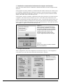
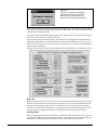
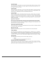
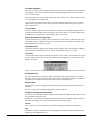
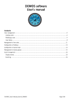
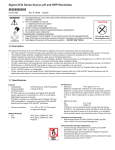
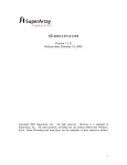
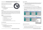
Field-Pro™
Field-Pro™ Configuration Software
Installation and Operation Manual
for Analog Output
Fluidyne
A Division of Engineering Measurements Co.
Field-Pro™
Table of Contents
Section 1: Installation ....................................... 3
Windows System Requirements ............................................................................. 3
The Field-Pro™ Package Contents .......................................................................... 3
Installing the Software ............................................................................................ 3
Uninstalling the Software ........................................................................................ 4
Connecting the Hardware ....................................................................................... 4
Section 2: Configuring a Flowmeter ................ 5
Start the Program. .................................................................................................. 5
Select the Correct Settings. .................................................................................... 5
Establish the Communication Link Between the Computer and Flowmeter. .......... 6
Configure the Flowmeter. ........................................................................................ 6
Meter Size ............................................................................................................... 7
Schedule/Class ....................................................................................................... 7
Outside Diameter .................................................................................................... 8
Inside Diameter ....................................................................................................... 8
Insertion Depth ....................................................................................................... 8
Application Temperature ......................................................................................... 8
Volume Units and Rate Time Base ......................................................................... 8
Maximum Flow Rate ............................................................................................... 8
Totalizer Multiple ..................................................................................................... 8
Analog Output ......................................................................................................... 8
Full-Scale Flow Rate and Output K-Factor ............................................................. 8
Flow Rate Smoothing.............................................................................................. 9
Time Constant ......................................................................................................... 9
Display Flow Rate and Display Total ....................................................................... 9
Display Hold Time ................................................................................................... 9
Clear Total ............................................................................................................... 9
Set Default Values ................................................................................................... 9
Report Output ......................................................................................................... 9
Print/Save Configuration Value Report ................................................................... 9
Cancel ..................................................................................................................... 9
Exit .......................................................................................................................... 9
Section 3: Accuracy ..........................................10
Hydro-Flow™ Series Models 1100 and 1200 .......................................................... 10
Hydro-Flow™ Series Model 2100 ............................................................................ 10
Hydro-Flow™ Series Models 2200 and 3100 .......................................................... 10
Section 4: The Monitoring Function ................11
Minimum Scale and Maximum Scale ...................................................................... 11
Update Interval ........................................................................................................ 11
Data Logging ........................................................................................................... 11
Microsoft and Windows are registered trademarks and Windows NT is a trademark of Microsoft Corporation.
LabWindows/CVI is a tradmark of National Instruments.
Field-Pro and Hydro-Flow are trademarks of Fluidyne, A Division of Engineering Measurements Company.
2
Section 1: Installation
Welcome to the Field-Pro™ configuration program for the Hydro-Flow™ Series of vortex flowmeters.
Together with the Field-Pro Communicator, the Field-Pro software is used to set the configuration
values for a Hydro-Flow flowmeter. The Field-Pro User’s Manual is a step by step guide to installing
the software, connecting the hardware and using the program to reconfigure your Hydro-Flow flowmeters.
WINDOWS SYSTEM REQUIREMENTS
To use the Field-Pro configuration program, you need the following hardware and software:
• Personal computer with 25 MHz 80386 or better, with math coprocessor (80486DX or Pentium
recommended)
• VGA resolution video adapter
• Microsoft® Windows® 3.1, Windows 95 or Windows NT™ version 4.0 or better
• 4 MB random-access memory (RAM); 8 MB RAM with Windows 95
• Approximately 3 MB available hard disk space
• EIA-232 serial port (COM1 through COM4 are supported) with standard 9-pin connector
THE FIELD-PRO PACKAGE CONTENTS
• Field-Pro Communicator
• Serial interface cable, 6 foot long 9-pin male to 9-pin female
• Power supply, 120 VAC 60 Hz input, 12 VDC 300 mA unregulated output
• Flowmeter cable with alligator clips for connecting to the flowmeter power terminals
• Two 31/2" high density floppy disks with the Field-Pro software
• Field-Pro Installation and Operation Manual
INSTALLING THE SOFTWARE
This section describes how to install the Field-Pro software.
1. Start Windows, if necessary.
2. Insert Disk 1 into your floppy disk drive.
3. For Windows 3.1: In the Program Manager, from the File menu, choose Run. Type
a:\SETUP.EXE and press enter. Follow the prompts.
For Windows 95 and Windows NT: From Start in the task bar, choose Run. Type a:\SETUP.EXE
[enter]. Follow the prompts.
The following files are installed in the directories shown, assuming that the default directories are not
changed during installation.
C:\FIELDPRO\FIELDPRO.BMP
C:\FIELDPRO\FIELDPRO.CAL
C:\FIELDPRO\FIELDPRO.EXE
C:\FIELDPRO\FIELDPRO.INI
C:\FIELDPRO\PANELS.UIR
C:\FIELDPRO\UNINST.EXE
C:\FIELDPRO\UNINST.LRM
C:\FIELDPRO\VORTCOMM.DLL
C:\CVIRTE\CVIRT4.EXE
C:\CVIRTE\BIN\CVIRT4.RSC
C:\CVIRTE\BIN\MSGRT4.TXT
C:\CVIRTE\FONTS\NISYSTEM.TTF
C:\CVIRTE\FONTS\NI7SEG.TTF
The CVIRTE directory includes the runtime files necessary for the National Instruments
LabWindows/CVI™ executables. If you already have LabWindows/CVI installed on your system,
then the CVIRTE directory is not created; the Field-Pro software uses the LabWindows/CVI runtime
files already installed on your system.
In addition to the files, a Windows program group titled “Field-Pro Configuration" is created with
two items
• Field-Pro Configuration Program
• Uninstall Field-Pro Configuration Program.
3
UNISTALLING THE SOFTWARE
If you need to remove the Field-Pro software from your hard drive, the “Uninstall Hydro-Flow Configuration” item will remove the files installed by SETUP.EXE specific to the Hydro-Flow configuration program, but will not remove the CVI runtime files.
CONNECTING THE HARDWARE
This section describes how to connect the Field-Pro Communicator to your flowmeter and your computer. Refer to Figure 1-1.
1. Connect the serial interface cable’s male connection to the serial port on the Field-Pro Communicator. Connect the female connection to the desired 9-pin (or 25-pin with adapter, not supplied)
serial port on your computer (COM1 through COM4 are supported).
2. Plug the power supply into an AC power outlet. Insert the power supply connector into the mating
connector on the Field-Pro Communicator.
3. The green indicator light on the left should be on and the indicator light on the right should be off.
4. Plug the flowmeter cable into the remaining connector on the Field-Pro Communicator.
5. Remove the cover of the flowmeter’s electronics enclosure. If the flowmeter terminals are wired to
an existing system, the wiring must be disconnected before using the configuration device.
6. Connect the red clip to the positive (+) flowmeter terminal and the black clip to the negative (–)
terminal. See Figure 1-2. If the positive and negative leads are reversed, neither the flowmeter nor
the configuration program will function properly, but no damage will occur. If your flowmeter has
an LCD display, verify that the display is working.
7. With the flowmeter connected, verify that both indicator LEDs on the Field-Pro Communicator
are lit.
Red and Black
Clips
Power
Supply
Connector
Indicator
Lights
Serial Port
(Computer Connection)
Flowmeter
Connection
Field-Pro™
A Division of Engineering Measurements Co.
Fluidyne
Figure 1-1
Figure 1-2
4
Section 2: Configuring a Flowmeter
1. Start the program.
For Windows 3.1: Select the “Field-Pro Configuration Program” icon from the Program Manager.
For Window 95 and Windows NT: Select Field-Pro Configuration from Start in the taskbar.
The Start-Up screen in Figure 2-1 appears.
NOTE: The first
time you run the
Field-Pro
program the Settings screen
will automatically open.
2. Select the correct settings.
Select the Settings button to access the Settings screen. Refer to Figure 2-2.
A Use the Comm Port control to select the serial port to which the Field-Pro Communicator is connected on your computer. COM1 through COM4 are supported.
B If printing is desired, use the Printed Report Line Offset control to enter the number of spaces to
be printed at the start of each line in the configuration value printed report. See Report Output on
page 9.
C Use the Display Picture control to check (uncheck) the box to enable (disable) the display of the
flowmeter graphic on the Start-Up screen. If your computer is slow in starting the Field-Pro
program, disabling the display of the flowmeter graphic may decrease the loading time.
D Use the Demo Mode control to check (uncheck) the box to enable (disable) the demonstration
mode. Demonstration mode will allow you to use the program without connecting the Field-Pro
Communicator and a flowmeter.
E If you enable Demo Mode, use the Demo Meter Type control to select the type of flowmeter you
would like the Field-Pro software to simulate for configuration.
F Use the Default Units control to select measuring units that are English based (gallons, etc.) or
Metric based (liters, etc.).
Select OK to return to the Start-Up screen.
Figure 2-1.
The Start-Up screen will automatically appear when you run the Field
Pro software. From the Start-Up
screen, select any of the five
functions of the software. Select
Exit to quit the program.
A
B
C
D
E
F
Figure 2-2.
The Settings screen is accessed by
selecting the Settings button on the
Start-Up screen.
5
3. Establish the communication link between the computer and flowmeter.
Select the Connect Meter button to establish the communication link between the computer and the
flowmeter.
If the program successfully establishes a communication link with the flowmeter, the window in Figure 2-3 appears, indicating the type of flowmeter connected. If the flowmeter has an LCD display,
the display should blank out momentarily, followed by the display test pattern and then the normal
display. Select OK to return to the Start-Up screen.
If the program is unable to establish a communication link with the flowmeter, the window in Figure
2-4 appears. Select OK to return to the Start-Up screen. Check that all cable connections to the
Field-Pro Communicator, flowmeter and computer are secure. Verify that the serial port on the computer to which the Field-Pro Communicator is connected is the selected Comm Port in the Settings
screen. Select the Connect Meter button to set up the communication link. Select OK when the window in Figure 2-3 appears to return to the Start-Up screen.
Volumetric Flowmeter
Analog Output
Firmware Version 7
6" Schedule 40
Figure 2-3.
Appears when the communication link has
been successfully established. The program
automatically identifies the type of flowmeter,
the type of output with which the flowmeter is
equipped, the firmware version in the
flowmeter's electronics module and the
current configured flowmeter size and pipe.
Figure 2-4.
Appears if the program is unable to establish
the communication link.
4. Configure the flowmeter.
Select Configuration to access the Configuration screen shown in Figure 2-5. The Configuration
screen allows you to select the values which affect the flowmeter’s operation
Figure 2-5.
Configuration screen appears when you select the
Configuration button from
the Start-Up screen.
6
Figure 2-6.
Appears if you select the Configuration
button from the Start-Up screen before
establishing the communication link
between the computer and the flowmeter.
If the window in Figure 2-6 appears, instead of the Configuration screen in Figure 2-5, the communication link with the flowmeter has not been established. Select OK. Select the Connect Meter button
to establish the communication link.
If you have selected Demo Mode in the Settings screen, changes made to the values in the configuration screen will not affect any connected flowmeter.
If you are not running Demo Mode and you make changes to the configuration, selecting Exit will
change the configuration of the connected flowmeter and return to the Start-Up screen; if you do not
want to make any changes, select Cancel to return to the Start-Up screen and leave the configuration
of the flowmeter unchanged.
The following describes the functions of the different controls appearing in the Configuration screen:
Meter Size
With the Meter Size control, you can select one of several inline and insertion flowmeter sizes, Other
Insertion or Custom/Inline. The Other Insertion option allows you to select any inside diameter, outside diameter and insertion depth, which is not listed in the meter size selections, for an insertion
flowmeter. The Custom/Inline option allows for configuration of an insertion flowmeter as if it were
an inline flowmeter, calibrated in a specific tee fitting other than those provided by Fluidyne.
Schedule/Class
When reconfiguring an insertion style flowmeter, the Schedule/Class control allows you to select one
of several pipe schedules or plastic pipe pressure classes. This control is grayed out when any inline
flowmeter size, Other Insertion or Custom/Inline options under Meter Size are selected.
7
Outside Diameter
The Outside Diameter control allows you to enter the nominal outside diameter of the pipe in which
an insertion flowmeter is installed. This control is grayed out when any inline flowmeter size is selected under the Meter Size control.
Inside Diameter
The Inside Diameter control allows you to enter the nominal inside diameter of the inline flowmeter
or the pipe in which an insertion flowmeter is installed. For inline meters, the inside diameter of the
flowmeter body is automatically set for the selected inline flowmeter size.
Insertion Depth
The Insertion Depth control is the nominal position of the sensor’s centerline relative to the outside
diameter of the pipe in which an insertion flowmeter is installed. This value will change depending
on the pipe size selected for the insertion flowmeter. For pipe sizes 3" through 6", the insertion depth
should be 1.75"; for pipe sizes 8" through 20", the insertion depth should be 3.5" measured from the
outside wall of the pipe.
Application Temperature
Enter the expected average temperature of the water in the intended application in degrees Fahrenheit. If the average temperature of the intended application is greater (less) than the specified maximum temperature for the selected flowmeter, the program will change the entered temperature to the
allowable maximum (minimum) temperature.
Volume Units and Rate Time Base
These controls allow you to select the measuring units for the flow rate/total to be displayed and used
for the output scaling of the flowmeter.
Maximum Flow Rate
Indicates the specified maximum flow rate in the selected units for the selected flowmeter.
Totalizer Multiple
The internal totalizer accumulates flow in the engineering units (i.e. gallons, liters, etc.) selected by
the user. Normally, the total flow will be show as "engineering units" x 10, "engineering units" x 100,
or "engineering units" x 1,000. The algorithms used internally in the flowmeter restrict the range of
values that can be entered. You will be warned and given appropriate limits if this range is exceeded.
Analog Output
The Analog Output control may be used to select the analog output to be:
•
•
disabled.
set to be proportional to the scaled and linearized flow rate.
Full-Scale Flow Rate and Output K-Factor
The full-scale flow rate is the flow rate that corresponds to an output current of 20 mA. The analog
output current cannot exceed 20 mA. Therefore, the full-scale flow rate value should be set to a value
greater than or equal to the maximum expected flow rate in the application.
8
Flow Rate Smoothing
Flow rate smoothing "evens" the usual fluctuations in the flow rate to maintain a more consistent output and display. There are two options for the smoothing algorithm built into the flowmeter firmware: Fast and Normal.
The Normal option uses a time constant equal to the Time Constant value. Thus, the Normal option
is recommended for most applications.
The Fast option uses a time constant which is dependent upon the change in the flow rate. The Fast
option effectively smooths the flow under steady-state conditions while allowing fast response to
large changes in flow.
Time Constant
The Time Constant control sets the time constant in seconds for the smoothing algorithm described
in the Flow Rate Smoothing control. The default value for this control is 5.0 seconds, which should
be adequate for most applications. The maximum value is 60 seconds.
Display Flow Rate and Display Total
If the flowmeter has an LCD display, these controls allow the user to select whether the flow rate, totalized flow or both are displayed. If only flow rate or totalized flow is displayed, the display is updated approximately ten times per second.
Display Hold Time
If both rate and total are displayed, the amount of time to display each is determined by the Display
Hold Time value. The default value is 3.0 seconds. The maximum value is 3.1 seconds.
Clear Total
The Clear Total control clears the internal flow totalizer. Some versions of the flowmeter do not support this feature; if this is the case, the Clear Total button will be grayed out. Selecting Clear Total
displays the window:
Select Yes to clear the flowmeter totalizer; select No to exit the window without clearing the totalizer.
Set Default Values
Select Set Default Values to change the display and output scaling values based upon the selected
flowmeter size. You would want to use this control to set the configuration values those specified in
the general specifications for the flowmeter, based on pipe size and output type.
Report Output
Select Printer to have the Configuration Value Report printed using the default Windows printer in
Windows.
Select File to have the Configuration Value Report saved as a disk file.
Print/Save Configuration Value Report
If Printer is selected in Report Output, this button will read Print Configuration Value Report. Selecting this button will print the report.
If Disk File is selected in Report Output, this button will read Save Configuration Report. Selecting
this button will prompt you for a file name and location for saving the report.
Cancel
Select Cancel to quit the Configuration screen without changing the flowmeter configuration.
Exit
Select Exit to quit the Configuration screen and program the flowmeter with the configuration data
displayed in the configuration screen.
9
Section 3: Accuracy
Hydro-Flow Series Models 1100 and 1200 Inline Flowmeters
It is important to remember that calibration of inline flowmeters is performed in the original flowmeter body. If the flowmeter sensor is moved to another inline flowmeter body, the calibration may
not meet the accuracy specifications for the flowmeter.
NOTE: For the
Model 2100,
custom weldolets
and saddles are supplied
by Fluidyne for each pipe
size. When removing the
Model 2100 flowmeter into
a different pipe size,
custome weldolets or
saddles need to be
provided by Fluidyne.
Hydro-Flow Series Model 2100 Fixed Insertion Flowmeters
As long as your Model 2100 was originally calibrated as an insertion flowmeter, you can reconfigure
your Model 2100 within a range of pipe sizes without any loss in accuracy. Because the flowmeter’s
stem length and the insertion depth varies by pipe size, you need to know for what pipe size your
Model 2100 was calibrated. If you reconfigure your Model 2100 for a pipe size in the same range as
the pipe size for calibration, there will be no loss of accuracy resulting from the reconfiguration and
use of the flowmeter in another pipe size.
The ranges of pipe sizes are as follows:
•
•
•
3" through 6"
8" through 14"
16" through 20"
For pipe sizes greater than 20", consult the factory as to whether or not your flowmeter can be installed in the larger pipe size.
Example: You have a Model 2100 calibrated for 10" pipe. You can reconfigure your flowmeter
within the range 8" through 14" and install the flowmeter without any loss in acuracy. You can not
reconfigure the flowmeter for pipe sizes 3" through 6" or pipe sizes 16" through 20".
Hydro-Flow Series Models 2200 and 3100
As long as your Model 2200 or 3100 was originally calibrated as an insertion flowmeter, you can
reconfigure your flowmeter for any pipe size between 3" and 20" without any loss in accuracy.
When installing your flowmeter in the new pipe size, refer to your Instruction and Operation Manual
for installation instructions, as installation varies by pipe size. For pipe sizes greater than 20", consult the the factory as to whether or not your flowmeter can be installed in the larger pipe size.
Model 1100,
shown with tee fitting
Model 2100,
shown with saddle mounting
10
Model 1200
Model 2200
Model 3100,
shown with
threadolet mounting
Section 4: The Monitoring Function
From the Start-Up screen, selecting the Monitor button accesses the Monitor screen. The Monitor
screen is an indication of the flow rate and scaled total flow in the engineering units selected in the
Configuration Screen. The values are updated in increments selected in the Update Interval control.
In order to use the monitor function, you must establish a communication link between the flowmeter
and the computer, as described on page 5.
The following describes the functions of the different controls appearing in the Monitoring screen.
Minimum Scale & Maximum Scale
The program will automatically set the Minimum Scale to 0 and the Maximum Scale to an even number greater than the maximum flow rate entered in the Maximum Flow Rate control in the Configuration screen. You can use these controls to enter different minimum and maximum values for the
graph on the Monitor screen.
Update Interval
Use the Update Interval control to select how often you want the screen to update possible changes in
the flow rate.
Data Logging
Turn the Data Logging control on to be able to save the monitoring information to file.
11
990621 (1/98)
600 Diagonal Hwy., Longmont, CO 80501
Tel (303) 651-0352 • Fax (303) 678-1754 • e-mail [email protected]