1
i
AllenBradley
PLS/DM Software
for
SLC Processors
for PLS/DM software
(Cat. No. 6556SPAKS)
for PLS software
(Cat. No. 6556SPLS)
for DM software
(Cat. No. 6556SDM)
User
Manual
Important User Information
Because of the variety of uses for the products described in this
publication, those responsible for the application and use of this
control equipment must satisfy themselves that all necessary steps
have been taken to assure that each application and use meets all
performance and safety requirements, including any applicable laws,
regulations, codes and standards.
The illustrations, charts, sample programs and layout examples
shown in this guide are intended solely for purposes of example.
Since there are many variables and requirements associated with any
particular installation, Allen-Bradley does not assume responsibility
or liability (to include intellectual property liability) for actual use
based upon the examples shown in this publication.
Allen-Bradley publication SGI-1.1, Safety Guidelines for the
Application, Installation, and Maintenance of Solid-State Control
(available from your local Allen-Bradley office), describes some
important differences between solid-state equipment and
electromechanical devices that should be taken into consideration
when applying products such as those described in this publication.
Reproduction of the contents of this copyrighted publication, in
whole or in part, without written permission of Allen-Bradley
Company, Inc., is prohibited.
Throughout this manual we use notes to make you aware of safety
considerations:
!
ATTENTION: Identifies information about practices
or circumstances that can lead to personal injury or
death, property damage or economic loss.
Attention statements help you to:
• identify a hazard
• avoid the hazard
• recognize the consequences
Important:
Identifies information that is critical for successful
application and understanding of the product.
PanelBuilder, PanelView and SLC are trademarks of Allen-Bradley Company, Inc.
Table of Contents
About This Preface . . . . . . . . . . . . . . . . . . . . . . . . . .
P-1
Who Should Use this Manual? . . . . . . . . . . . . . . . . . . . . . .
Intended Audience . . . . . . . . . . . . . . . . . . . . . . . . . . . . . . .
Purpose of this Manual . . . . . . . . . . . . . . . . . . . . . . . . . . . .
Related Documentation . . . . . . . . . . . . . . . . . . . . . . . . . . .
Allen-Bradley Support . . . . . . . . . . . . . . . . . . . . . . . . . . . .
Local Product Support . . . . . . . . . . . . . . . . . . . . . . . . . .
Technical Product Assistance . . . . . . . . . . . . . . . . . . . . .
Your Questions or Comments on this Manual . . . . . . . . . .
Notes: . . . . . . . . . . . . . . . . . . . . . . . . . . . . . . . . . . . . . .
P-1
P-1
P-1
P-2
P-2
P-2
P-3
P-3
P-4
Introducing PLS/DM Software . . . . . . . . . . . . . . . . . .
1-1
What Is PLS/DM Software? . . . . . . . . . . . . . . . . . . . . . . . . .
Applying This Manual to PLS/DM Applications . . . . . . . . .
What Is a Programmable Limit Switch (PLS)? . . . . . . . . . . . .
How a PLS Channel Works . . . . . . . . . . . . . . . . . . . . . . .
What Is Die Monitoring (DM)? . . . . . . . . . . . . . . . . . . . . . . .
How a DM Channel Works . . . . . . . . . . . . . . . . . . . . . . .
What is an SLCbased Control System? . . . . . . . . . . . . . . . .
1-1
1-1
1-2
1-2
1-3
1-3
1-4
Quick Start . . . . . . . . . . . . . . . . . . . . . . . . . . . . . . . .
2-1
Required Tools and Equipment . . . . . . . . . . . . . . . . . . . . . .
Procedures . . . . . . . . . . . . . . . . . . . . . . . . . . . . . . . . . . . .
Notes: . . . . . . . . . . . . . . . . . . . . . . . . . . . . . . . . . . . . . .
2-1
2-2
2-4
Determining Your DM Requirements . . . . . . . . . . . . .
3-1
Objectives . . . . . . . . . . . . . . . . . . . . . . . . . . . . . . . . . . . . .
Operation of DM Input Modes . . . . . . . . . . . . . . . . . . . . . . .
A Comment on Cyclic, Singlepart, and Inposition Modes .
Cyclic (CYC) Use this mode to verify that a pulse from the
sensor (OFFONOFF) occurred within the window
once each stroke. For example, use it to detect that a
part moved past a monitor. . . . . . . . . . . . . . . . . . . . . .
Singlepart (SGP) Use this mode to verify that the sensor
signal turned ON within the window and OFF within the
window or the 45o warning zone each stroke. If it turns
OFF late within the warning zone, the channel output is
a warning. Use it to detect if a part is ejected or inserted at
the correct moment in the press stroke. . . . . . . . . . . . .
3-1
3-1
3-2
3-2
3-2
ii
Table of Contents
Inposition (POS) Use this mode to verify that the sensor
signal remained ON within the entire window once each
stroke. The signal must cycle OFF outside the window.
Use it to detect if ejector and other automation parts are
retracted to home position. . . . . . . . . . . . . . . . . . . . . .
Track Mode (TRK) Use track mode with a PLS output to verify
that an action took place. The PLS output starts the track
mode timer and the desired action at the same time. The
trackmode input signal must be detected within the preset
time interval of the trackmode timer and remain ON until the
PLS output turns OFF. Otherwise, the software is designed to
indicate a fault. Track mode (input) and PLS (output) use the
same channel. . . . . . . . . . . . . . . . . . . . . . . . . . . . . .
Transfer Mode (XFR) Use transfer mode to monitor the
transfer of a part in a transfer press, from one transfer
location to the next for each stroke of the press. Typically,
each transfer location has a single partdetect sensor.
The logic of transfer mode is similar to that of a firstin
firstout (FIFO) shift register. It monitors die locations in
sequence, a pair at a time. You assign consecutive
channels to consecutive die locations in the sequence. .
Static Mode (STC) Use this mode to detect that an event
occurred independent of the press stroke. When a static
mode input turns Off, the programmed output is turned On.
For example, use it to detect end of stock. . . . . . . . . . .
Analog (ALG) Use this mode to verify that a signal from an
analog sensor remained within minimum and maximum
limits during the programmed window. The software
declares a fault signal when it detects the analog signal
outside either limit. For example, use it to monitor the
thickness of ribbon material moving continuously. . . . .
Output Responses for DM Channels . . . . . . . . . . . . . . . . . .
Counting Your DM Input Channels . . . . . . . . . . . . . . . . . . .
Worksheet A for DM Input Channels . . . . . . . . . . . . . . . . . .
Notes: . . . . . . . . . . . . . . . . . . . . . . . . . . . . . . . . . . . . . .
3-2
3-3
3-3
3-4
3-4
3-4
3-4
3-5
3-6
Determining Your PLS Requirements . . . . . . . . . . . .
4-1
Objectives . . . . . . . . . . . . . . . . . . . . . . . . . . . . . . . . . . . . .
Operation of the Programmable Limit Switch (PLS) . . . . . . . .
Operation of the PLS Output With a DM Track mode Input .
Counting Your PLS Channels . . . . . . . . . . . . . . . . . . . . . . .
Worksheet B for PLS Output Channels . . . . . . . . . . . . . . . .
Notes: . . . . . . . . . . . . . . . . . . . . . . . . . . . . . . . . . . . . . .
4-1
4-1
4-2
4-2
4-3
4-4
Table of Contents
iii
Setting Up System Hardware . . . . . . . . . . . . . . . . . . .
5-1
Objectives . . . . . . . . . . . . . . . . . . . . . . . . . . . . . . . . . . . . .
Selecting I/O Modules . . . . . . . . . . . . . . . . . . . . . . . . . . . . .
Compute Power for Selecting a Power Supply . . . . . . . . . . .
Hardware Requirements for an Example Standalone PLS/DM
Hardware Requirements for an Example PLS/DM and
Clutch/Brake System . . . . . . . . . . . . . . . . . . . . . . . . . . .
Hardware Requirements for an Example PLS/DM
with Other Logic . . . . . . . . . . . . . . . . . . . . . . . . . . . . . .
Considerations When Setting Up Analog Channels . . . . . . . .
List I/O Functions on Preaddressed Worksheets . . . . . . . . .
Worksheet C for DM Inputs & I/O Addresses . . . . . . . . . . . .
Worksheet D for PLS Outputs & I/O Addresses . . . . . . . . . . .
Worksheet D for PLS Outputs & I/O Addresses . . . . . . . . . . .
Worksheet E for Other Inputs & I/O Addresses . . . . . . . . . . .
Worksheet F for Other Outputs & I/O Addresses . . . . . . . . . .
Notes: . . . . . . . . . . . . . . . . . . . . . . . . . . . . . . . . . . . . . .
5-1
5-1
5-3
5-5
5-7
5-9
5-9
5-10
5-11
5-11
5-12
5-13
5-14
Installing Your Software . . . . . . . . . . . . . . . . . . . . . . .
6-1
Chapter Objective . . . . . . . . . . . . . . . . . . . . . . . . . . . . . . .
How the Installation of PLD/DM Software Affects
Your Hard Drive . . . . . . . . . . . . . . . . . . . . . . . . . . . . . .
Installing PLS/DM Software . . . . . . . . . . . . . . . . . . . . . . . .
6-1
6-1
6-1
Programming Strategy . . . . . . . . . . . . . . . . . . . . . . . .
7-1
Objectives . . . . . . . . . . . . . . . . . . . . . . . . . . . . . . . . . . . . .
Strategy for Writing Your Ladder Logic . . . . . . . . . . . . . . . . .
PLS/DM as Standalone Software . . . . . . . . . . . . . . . . . . .
Program Scan for Standalone PLS/DM Software . . . . . . .
PLS/DM Used with Clutch/Brake Software . . . . . . . . . . . . .
Program Scan for Combined PLS/DM and C/B Software . .
7-1
7-1
7-1
7-2
7-3
7-3
Programming DM Data . . . . . . . . . . . . . . . . . . . . . . . .
8-1
Objectives . . . . . . . . . . . . . . . . . . . . . . . . . . . . . . . . . . . . .
Mapping DM Hardware Addresses into the Data Table . . . . .
Writing Ladder Logic to Move DM Inputs into the Data Table .
Programming Other Software Inputs . . . . . . . . . . . . . . . . . .
Programming DM Outputs . . . . . . . . . . . . . . . . . . . . . . . . .
Notes: . . . . . . . . . . . . . . . . . . . . . . . . . . . . . . . . . . . . . .
8-1
8-1
8-2
8-3
8-5
8-6
5-6
iv
Table of Contents
Programming PLS Data . . . . . . . . . . . . . . . . . . . . . . .
9-1
Objectives . . . . . . . . . . . . . . . . . . . . . . . . . . . . . . . . . . . . .
Mapping Resolver Inputs into the Data Table . . . . . . . . . . . .
Writing Ladder Logic to Move Resolver Inputs into
the Data Table . . . . . . . . . . . . . . . . . . . . . . . . . . . . . . .
Mapping PLS Outputs to Hardware Addresses . . . . . . . . . . .
Programming PLS Outputs . . . . . . . . . . . . . . . . . . . . . . . . .
Notes: . . . . . . . . . . . . . . . . . . . . . . . . . . . . . . . . . . . . . .
9-1
9-1
9-1
9-2
9-2
9-4
Programming Your Counters . . . . . . . . . . . . . . . . . . .
10-1
Objectives . . . . . . . . . . . . . . . . . . . . . . . . . . . . . . . . . . . . .
Mapping Counter Inputs into the Data Table . . . . . . . . . . . . .
Writing Ladder Logic to Move Counter Inputs into the
Data Table . . . . . . . . . . . . . . . . . . . . . . . . . . . . . . . . . .
Mapping Counter Outputs to Hardware Addresses . . . . . . . .
Programming Counter Outputs . . . . . . . . . . . . . . . . . . . . . .
10-1
10-1
10-1
10-2
10-2
Setting Up a Password and Compensating
for Press Speed . . . . . . . . . . . . . . . . . . . . . . . . .
11-1
Objectives . . . . . . . . . . . . . . . . . . . . . . . . . . . . . . . . . . . . .
Master Password: What It Is, and How to Set It Up . . . . . . . .
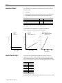
Pressspeed Compensation: What It Is, and When to Use It . .
When Do You Use it? . . . . . . . . . . . . . . . . . . . . . . . . . . .
How Does It Work? . . . . . . . . . . . . . . . . . . . . . . . . . . . . . .
How Do You Set It Up? . . . . . . . . . . . . . . . . . . . . . . . . . . . .
11-1
11-1
11-1
11-1
11-2
11-2
Customizing Your PanelView Screen Lists . . . . . . . . .
12-1
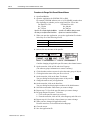
Chapter Objectives . . . . . . . . . . . . . . . . . . . . . . . . . . . . . . .
Changing the Names of Part Files and Channels . . . . . . . . .
Worksheet G for Part File Names . . . . . . . . . . . . . . . . . .
Worksheet H for DM Channel Names . . . . . . . . . . . . . . . .
Worksheet I for Names of Spare Setpoints . . . . . . . . . . . .
Procedure to Change Partfile and Channel Names . . . . . .
Changing the Names of Spare Setpoints . . . . . . . . . . . . . . .
Procedure to Change Names of Spare Setpoints . . . . . . .
Adding Screens to the PanelView Program . . . . . . . . . . . . . .
Notes: . . . . . . . . . . . . . . . . . . . . . . . . . . . . . . . . . . . . . .
12-1
12-1
12-2
12-2
12-3
12-4
12-5
12-5
12-5
12-6
Using DM Screens . . . . . . . . . . . . . . . . . . . . . . . . . . .
13-1
Objectives . . . . . . . . . . . . . . . . . . . . . . . . . . . . . . . . . . . . .
Using Typical Features . . . . . . . . . . . . . . . . . . . . . . . . . . . .
Using Function Keys . . . . . . . . . . . . . . . . . . . . . . . . . . .
Entering Your Password . . . . . . . . . . . . . . . . . . . . . . . . .
Reading Machine Status . . . . . . . . . . . . . . . . . . . . . . . . .
13-1
13-1
13-1
13-1
13-1
Table of Contents
v
Using Main Menu and Status Screens . . . . . . . . . . . . . . . . .
Using Screens for an Active Job . . . . . . . . . . . . . . . . . . . . .
Using Screens to Create a New Part File . . . . . . . . . . . . . . .
Downloading a Part File . . . . . . . . . . . . . . . . . . . . . . . . .
13-2
13-3
13-5
13-6
Using PLS Screens . . . . . . . . . . . . . . . . . . . . . . . . . .
14-1
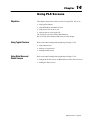
Objectives . . . . . . . . . . . . . . . . . . . . . . . . . . . . . . . . . . . . .
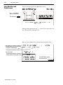
Using Typical Features . . . . . . . . . . . . . . . . . . . . . . . . . . . .
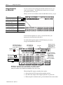
Using Main Menu and Status Screens . . . . . . . . . . . . . . . . .
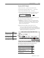
Using Screens for an Active Job . . . . . . . . . . . . . . . . . . . . .
Procedure to Edit PLS Setpoints . . . . . . . . . . . . . . . . . . .
Using Screens to Create a New Part File . . . . . . . . . . . . . . .
Downloading a Part File . . . . . . . . . . . . . . . . . . . . . . . . .
14-1
14-1
14-1
14-2
14-3
14-4
14-6
Using Screens for Counters and Spare Setpoints . . .
15-1
Objectives . . . . . . . . . . . . . . . . . . . . . . . . . . . . . . . . . . . . .
Using Main Menu and Status Screens . . . . . . . . . . . . . . . . .
Setting Up Counters 1 and 2 . . . . . . . . . . . . . . . . . . . . . . .
Entering Spare Setpoints For an Active Job . . . . . . . . . . . . .
Creating Spare Setpoints in a New Part File . . . . . . . . . . . . .
Downloading a Part File . . . . . . . . . . . . . . . . . . . . . . . . .
Notes: . . . . . . . . . . . . . . . . . . . . . . . . . . . . . . . . . . . . . .
15-1
15-1
15-1
15-2
15-4
15-5
15-6
Testing DM and PLS Channels . . . . . . . . . . . . . . . . . .
16-1
Objectives . . . . . . . . . . . . . . . . . . . . . . . . . . . . . . . . . . . . .
Testing DM Channels . . . . . . . . . . . . . . . . . . . . . . . . . . . . .
Procedure for Testing DM Channels . . . . . . . . . . . . . . . . .
Testing PLS Channels . . . . . . . . . . . . . . . . . . . . . . . . . . . .
Procedure for Testing PLS Channels . . . . . . . . . . . . . . . .
Testing the Resolver Input . . . . . . . . . . . . . . . . . . . . . . . . . .
Testing a Transfermode Channel . . . . . . . . . . . . . . . . . . . .
Procedure . . . . . . . . . . . . . . . . . . . . . . . . . . . . . . . . . . .
Testing a Trackmode DM/PLS Channel . . . . . . . . . . . . . . . .
Procedure . . . . . . . . . . . . . . . . . . . . . . . . . . . . . . . . . . .
16-1
16-1
16-2
16-2
16-3
16-3
16-4
16-5
16-5
16-6
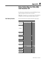
Data Table Map for PLS, DM, and Counter I/O . . . . . .
A-1
Data Table by Function . . . . . . . . . . . . . . . . . . . . . . . . . . . .
Data Table by File Address . . . . . . . . . . . . . . . . . . . . . . . . .
A-1
A-2
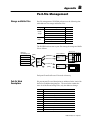
Partfile Management . . . . . . . . . . . . . . . . . . . . . . . . .
B-1
Storage and Buffer Files . . . . . . . . . . . . . . . . . . . . . . . . . . .
Partfile Word Descriptions . . . . . . . . . . . . . . . . . . . . . . . . .
B-1
B-1
Preface
About This Preface
Read this preface to familiarize yourself with the rest of the manual.
This preface covers the following topics:
•
•
•
•
•
Who Should
Use this Manual?
Intended Audience
who should use this manual
intended audience
purpose of this manual
related documentation
Allen–Bradley support
Use this manual if you are responsible for designing, installing,
programming, or troubleshooting control systems that use
Allen–Bradley small logic controllers.
You must have a basic understanding of SLC 500t programmable
controllers and related products, and the ladder logic instructions
required to control your application. Specifically, for using:
• Advance Programming Software (APS)
– create, edit, save, and download your ladder logic
• PanelBuilder Software
– basics of PanelBuilder including downloading a file
• ApplicationBuilder Software (required for Clutch/Brake system)
– compile subroutines
If not, consider contacting your local Allen–Bradley representative for
information on available training courses before using this product.
Purpose of this Manual
This manual is a reference guide for setting up, programming, and
using a hardware/software control system.. It describes the
procedures that you use to:.
•
•
•
•
•
•
determine system requirements
set up system hardware
install the software
customize the system to suit your application
use the screen displays
test system operation
Publication 65566.5.6 - April 1996
P–2
Related Documentation
The following documents contain additional information concerning
Allen–Bradley SLCt products. To obtain a copy, contact your local
Allen–Bradley office or distributor.
For
Read This Document
An overview of the SLC 500 family of products
SLC 500 System Overview
A description on how to install and use your Modular SLC 500
programmable controller
A procedural manual for technical personnel who use APS to
develop control applications
A reference manual that contains status file data, instruction set,
and troubleshooting information about APS
An introduction to APS for first-time users, containing basic
concepts, focusing on simple tasks and exercises, and allowing
the reader to begin programming in the shortest time possible
Installation & Operation Manual for Modular
Programmable Controllers
Allen-Bradley Advanced Programming Software
(APS) User Manual
Allen-Bradley Advanced Programming Software
(APS) Reference Manual
A training and quick reference guide to APS
A procedural and reference manual for technical personnel who
convert APS files to ASCII and conversely ASCII to APS files
In-depth information on grounding and wiring Allen-Bradley
programmable controllers
A description of differences between solid-state programmable
controller products and hard-wired electromechanical devices
An article on wire sizes and types for grounding electrical
equipment
A complete listing of current Allen-Bradley documentation, with
ordering instructions for CD-ROM and foreignlanguage versions.
A glossary of industrial automation terms and abbreviations
A good introduction to get you started using PanelBuilder 550
Allen-Bradley Support
1747-6.2
1747-6.4
1747-6.11
Getting Started Guide for APS
1747-6.3
SLC 500 Software Programmer's Quick Reference
Guide available on PASSPORT at a list price of $50.
ABT-1747-TSG001
APS Import/Export User Manual
1747-6.7
Allen-Bradley Programmable Controller
Grounding and Wiring Guidelines
1770-4.1
Application Considerations for Solid-State Controls
SGI-1.1
National Electrical Code
National Fire
Protection Assoc
of Boston, MA.
Allen-Bradley Publication Index
SD499
Allen-Bradley Industrial Automation Glossary
AG-7.1
Getting Started with PanelBuilder & PanelView 550
2711804
Allen–Bradley offers support services worldwide, with over 75
Sales/Support Offices, 512 authorized Distributors and 260 authorized
Systems Integrators located throughout the United States alone, plus
Allen–Bradley representatives in every major country in the world.
Local Product Support
Contact your local Allen–Bradley representative for:
• sales and order support
• product technical training
• warranty support
• support service agreements
Publication 65566.5.6 - April 1996
Number
1747-2.30
P–3
Technical Product Assistance
If you need to contact Allen–Bradley for technical assistance, please
review the information in the Troubleshooting chapter first. Then
call your local Allen–Bradley representative.
Your Questions or Comments on this Manual
If you find a problem with this manual, please notify us of it on the
enclosed Publication Problem Report.
If you have any suggestions for how this manual could be made
more useful to you, please contact us at the address below:
Allen–Bradley Company, Inc.
Automation Group
Technical Communication Dept. 602V – T122
P.O. Box 2086
Milwaukee, WI 53201–2086
Publication 65566.5.6 - April 1996
P–4
Notes:
Publication 65566.5.6 - April 1996
Chapter
1
Introducing PLS/DM Software
What Is PLS/DM Software?
PLS/DM software is a group of engineered press-control products for
Allen-Bradley SLC processors. This software controls the operation of:
• programmable limit switch (PLS) for crankshaft synchronization
• die monitoring (DM) to protect your press dies and machinery
We have packaged PLS/DM software in three versions to maximum
SLC memory capacity (words) available for the additional custom
programming of your application. All three versions contain:
•
•
•
•
counters for monitoring system or job duration
spare setpoints for controlling custom functions
part-file management to store and retrieve job setups
interface to Clutch/Brake Software (cat. no. 6556-SCB)
The three versions are:
Version
Cat. No.
Description
Words
PLS/DM
6556SPAKS
Programmable Limit Switch and Die Monitoring
12,681
DM
6556SDM
Die Monitoring (PLS not included)
12,037
PLS
6556SPLS
Programmable Limit Switch (DM not included)
8,626
We provide this software in the form of ladder logic, PanelView
application files, and Software Application Modules (SAM s).
All three versions are designed as stand-alone software or for use
with Allen-Bradley Clutch/Brake Software (cat. no. 6556-SCB).
Applying This Manual to PLS/DM Applications
We have written this manual to cover all three versions of the software.
If your system does not use PLS, DM, counters, and/or spare setpoints,
you may skip those chapters or sections of chapters pertaining to them.
Publication 65566.5.6 - April 1996
1–2
Introducing PLS/DM Software
What Is a Programmable
Limit Switch (PLS)?
The Allen-Bradley Programmable Limit Switch is ladder logic for an
SLC-based control system that times or sequences outputs according
to precise and repeatable positions of a crankshaft. Crankshaft positions
are monitored by a resolver. You can use PLS to integrate auxiliary
press machinery such as lifters, grippers blow-off valves, and
inter-press automation into your stamping press control system.
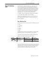
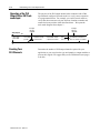
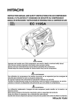
How a PLS Channel Works
You preset the rotational position (preset angle) at which you want
the PLS output to turn ON. You select how you want the PLS output
to turn OFF: by preset angle or preset time.
Angular preset to
turn output ON
0o
Neartop Zone
Down
stroke 90o
Zone
Up
270o stroke
Zone
Angular or time
preset to
turn output OFF
Bottom
180o
Then, you can program your application-specific output response,
such as using the PLS output bit as a trigger to:
• initiate part movement between presses in a transfer line
• look for correct part movement with a die monitor track function
• initiate die automation devices such as grippers and lifters
Publication 65566.5.6 - April 1996
Introducing PLS/DM Software
What Is Die Monitoring
(DM)?
1–3
Allen-Bradley Die/Automation Monitoring is ladder logic for an
SLC processor and PanelView terminal designed to monitor a
variety of conditions synchronized with the rotation of a stamping
press crankshaft. Crankshaft positions are monitored by a resolver.
You can use this product to detect the absence, mis-alignment, or
unwanted presence of material moving through an automated
stamping process. The software and associated hardware:
• monitor a variety of logical inputs to detect deviant conditions
• set a fault bit when it detects a deviant condition
When used with clutch/brake software (cat. no. 6556-SCB), you
select whether the fault bit initiates a warning, stop-on-top, or a
stop-now condition.
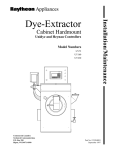
How a DM Channel Works
You select one of several operational modes for a DM input, such as:
•
•
•
•
•
•
cyclic
in-position
track
transfer
analog
static
As long as the logic detects expected conditions, no action is taken.
When the logic detects a deviant condition, it sets a fault bit.
For example, in cyclic mode an input switch is expected to close
within a preset zone of rotation that we call a window.
Cyclic Mode
Transition Diagram
a
b
Expected Transition Occurs
Within Window
Input is NOT ALLOWED
When Sensor:
Sensor turns ON then OFF
within window ab
1. stays ON beyond the window
Which Results in a
Fault SIGNAL Sent After:
window goes OFF
2. turns ON outside the window
sensor turns ON
3. remains OFF for the cycle
next window goes ON
(Pulsetype signal)
You can use a DM input to monitor an individual station such as for
in-position mode, or use them in a sequence of transfer locations to
monitor the progression of parts such as for transfer mode. The
software provides up to 16 DM selectable input channels.
Publication 65566.5.6 - April 1996
1–4
Introducing PLS/DM Software
What is an SLCbased
Control System?
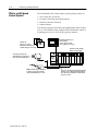
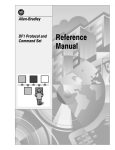
The Allen-Bradley SLC-based control system typically consists of:
•
•
•
•
one or more SLC processors
I/O chassis with input and output modules
PanelView Interface Terminal
control software
Our control system for die monitor and programmable limit switches
(cat. no. 6556-SPAKS), when combined with clutch/brake control of
a stamping press (cat. no. 6556-SCB), typically contains:
PanelView terminal lets you
- enter setpoints
- observe operation, and
- store setup files for use later
Software for
SLC processor and
PanelView terminal that you
combine with your control logic.
I/O chassis holds modules
that process I/O signals.
A resolver provides precise
rotational inputs to monitor press
stroke for PLS and C/B control.
Nj
Power
Supply
Nj
Multiple switches provide DM inputs
to monitor correct part movement
synchronized with the press stroke.
Publication 65566.5.6 - April 1996
SLC processor with PLS, DM, and C/B software
monitors resolver, DM, and automation inputs;
and controls the clutch/brake mechanism and
your press control.
Chapter
2
Quick Start
This chapter can help you to get started using PLS/DM Software
(cat. no. 6556-SPAKS). We assume that you have an understanding of
SLC 500 products, electronic press control, and the ladder logic
instructions required to control your application.
Because this chapter is a start-up guide for experienced users, it does
not contain detailed explanations about the procedures. It does,
however, refer to other chapters in this book where you can get more
information. It provides a good overview for less experienced users.
If you feel that the information we present is not sufficient for you to
complete a step, always read the referenced chapters and other
recommended documentation before attempting to do the step.
This chapter:
• tells you what tools and equipment you need
• presents procedures for setting up and testing the system
Required Tools and
Equipment
Have the following tools and equipment ready:
• medium blade screwdriver for connecting wires
• programming equipment
(All programming examples shown in this manual demonstrate
the use of Allen–Bradley’s Advanced Programming Software
(APS) for personal computers.)
• SLC processor, I/O chassis, I/O modules, resolver and resolver
input module, power supply, PanelView 550 or 900 Terminal
• input switches and output devices
Publication 65566.5.6 - April 1996
2–2
Quick Start
Procedures
1.
Check the contents of shipping box.
Reference
Unpack the shipping box making sure that the contents include in addition to this User Manual:
• Software Diskette (cat. no. 6556SPAKS)
• Software License Sticker (to affix to your SLC processor)
If the contents are incomplete, call your local Allen-Bradley representative for assistance.
2.
Familiarize yourself with PLS and DM operation, and with these
procedures for setting up and using the system.
3.
If using DM, determine your DM requirements.
Determine the modes and quantity of DM input channels, and locations and types of input switches.
We provide worksheet A for your convenience.
Use this information to determine types and quantity of input modules.
4.
If using PLS, determine your PLS requirements.
Determine the quantity of PLS output channels, and how they synchronize with your application.
We provide worksheet B for your convenience.
Use this information to determine types and quantity of output modules.
5.
Set up your system hardware.
With information on Worksheets A and B, determine:
• slot locations of input and output modules
• list of hardware inputs for each input module
• list of hardware outputs for each output module
We provide worksheets CF for your convenience.
Use this information to determine and list:
• hardware addresses for mapping inputs into the data table (Worksheets C and E)
• hardware addresses for mapping outputs from the data table (Worksheets D and F)
Chapters 1 & 2
Chapter 3
Fill out
Worksheet A
Chapter 4
Fill out
Worksheet B
Chapter 5
Use
Worksheets A & B
to fill out
Worksheets CF
6.
Install your PLS/DM software.
Chapter 6
7.
Understand the purpose of your ladder logic and how we subdivided
program files for faster system operation.
Chapter 7
8.
Program DM channel inputs and outputs, and other system inputs.
Chapter 8
With information on Worksheets C and E, write ladder logic to:
• map DM channel inputs into the data table
• map resolver and analog inputs into the data table
• map other system inputs into the data table
• program DM outputs
Publication 65566.5.6 - April 1996
Use
Worksheets C & E
and Appendix A
Quick Start
9.
Program PLS channel inputs and outputs.
Chapter 9
With information on Worksheets D and F, write ladder logic to:
Use
Worksheets D & F
and Appendix A
• map resolver inputs into the data table (if not already done in chapter 8)
• program PLS outputs
10.
Program your counters.
Chapter 10
For each of the two counters, write ladder logic to:
• map counter inputs into the data table
• program counter done bits
11.
Appendix A
Set up the password and compensate for press speed.
Chapter 11
Use your programming terminal to enter program constants directly into the data table for:
• master password
• speedcontrol constants A, B, and C in the algorithm Ax2 + Bx + C
12.
2–3
Appendix A
Customize your PanelView Screen Lists.
Chapter 12
Use your programming terminal to change listed names displayed on PanelView screens from default
to those that suit your application for:
• part files 120
• channels 116
• spare setpoints 110
13.
Use PanelView screens to operate your system.
Chapters 1315
Use screens to:
• create part files for future use
• edit/monitor part files for an active job
• set up counters
• enter spare setpoints
14.
Test DM and PLS channels.
Chapter 16
Use screens to test:
• DM and PLS channels
• resolver inputs
• transfermode channels
• trackmode DM/PLS channels
Publication 65566.5.6 - April 1996
2–4
Quick Start
Notes:
Publication 65566.5.6 - April 1996
Chapter
3
Determining Your DM
Requirements
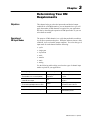
Objectives
This chapter helps you select the input mode and desired output
condition for each DM channel so you can determine how you will
apply the number of DM channels as required for your application.
We start by describing the operation of DM input modes so you can
select them as needed.
Operation of
DM Input Modes
The purpose of DM channels is to verify that predictable conditions
in your press operation take place. When the software detects a fault
condition, it sets a selectable output condition. You select the type of
input mode for each channel from the following:
•
•
•
•
•
•
•
cyclic
single-part
in-position
track
transfer
static
analog
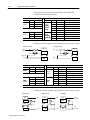
Use the following table to help you select the types of channel input
modes required for your application.
When Input Signals Are:
We Call This Input Mode:
Used, For Example To:
Synchronized with crankshaft rotation, and
detected within a zone or rotation (window)
Cyclic, Singlepart,
or In position
detect parts in position,
or ejected
Within a preset timed interval
started with a PLS output
Track
verify that a programmed PLS action
took place
Synchronized with crankshaft rotation as parts
are moved through multiple transfer locations
Transfer
verify the progression of the part from
one transfer location to the next
Independent of press stroke
Static
detect the end of stock
Based on measurement with an analog sensor
Analog
measure stripper position or
counterbalance pressure
Publication 65566.5.6 - April 1996
3–2
Determining Your DM Requirements
A Comment on Cyclic, Singlepart, and Inposition Modes
Input signals for these modes are synchronized with the rotation of the
crankshaft and must be detected within a zone of crankshaft rotation.
We call this zone of crankshaft rotation a window. For example, a
part-detect signal could be expected within a window of 80-110o to
indicate that a part was inside a die before it was hit by a stroke.
When the software detects input signals that are different from those
described here, the software generates a fault signal. We graphically
define these (window) inputs as follows:
angle ON
Window
angle OFF
ON
Crankshaft
rotation
OFF
Input
transition
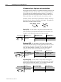
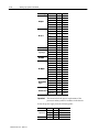
Cyclic (CYC) Use this mode to verify that a pulse from the sensor
(OFF-ON-OFF) occurred within the window once each stroke. For
example, use it to detect that a part moved past a monitor.
Transition Diagram
a
b
For These
Expected Transitions
Input is NOT ALLOWED
When Sensor:
Which Results in a
Fault Signal Sent After:
Sensor turns ON then OFF
within window
1. stays ON beyond window
window goes OFF
2. turns ON outside window
sensor turns ON
3. remains OFF for the cycle
next window goes ON
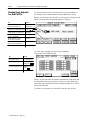
Singlepart (SGP) Use this mode to verify that the sensor signal
turned ON within the window and OFF within the window or the 45o
warning zone each stroke. If it turns OFF late within the warning
zone, the channel output is a warning. Use it to detect if a part is
ejected or inserted at the correct moment in the press stroke.
Transition Diagram
b
a
warning
zone
45o
For These
Expected Transitions
Input is NOT ALLOWED
When Sensor:
Which Results in a
Fault Signal Sent After:
Sensor turns ON within window,
then OFF within window or
warning zone.
1. stays ON after warning zone
window goes OFF
2. turns ON outside window
sensor turns ON
3. remains OFF for the cycle
next window goes ON
Inposition (POS) Use this mode to verify that the sensor signal
remained ON within the entire window once each stroke. The signal
must cycle OFF outside the window. Use it to detect if ejector and
other automation parts are retracted to home position.
Transition Diagram
a
Publication 65566.5.6 - April 1996
b
For These
Expected Transitions
Input is NOT ALLOWED
When the Sensor Signal:
Which Results in a
Fault signal Sent After:
Sensor turns ON before,
and OFF after window
1. turns OFF before window goes OFF
sensor turns OFF
2. does not turn OFF outside window
next window goes ON
3. remains OFF for the cycle
next window goes OFF
Determining Your DM Requirements
3–3
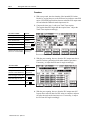
Track Mode (TRK) Use track mode with a PLS output to verify that
an action took place. The PLS output starts the track-mode timer
and the desired action at the same time. The track-mode input signal
must be detected within the preset time interval of the track-mode
timer and remain ON until the PLS output turns OFF. Otherwise, the
software is designed to indicate a fault. Track mode (input) and PLS
(output) use the same channel.
Timing Diagram
Trackmode
sensor signal
must be OFF.
PLS input
turns PLS
output ON
PLS input
turns PLS
output OFF
Time
Sensor signal
to PLS channel
goes ON.
PLS output starts
machine motion and
trackmode timer
Trackmode sensor signal
must turn ON to indicate
completion of movement.
Trackmode
timer
times out
If trackmode sensor signal
goes ON after trackmode timer
times out, software sets a fault bit.
Time required for one press stroke
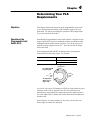
Transfer Mode (XFR) Use transfer mode to monitor the transfer of a
part in a transfer press, from one transfer location to the next for each
stroke of the press. Typically, each transfer location has a singlepart-detect sensor. The logic of transfer mode is similar to that of a
first-in-first-out (FIFO) shift register. It monitors die locations in
sequence, a pair at a time. You assign consecutive channels to
consecutive die locations in the sequence.
Configure the first input in a transfer-mode sequence (upstream
input) with an input switch programmed to either one of:
• B46/105 (XFR-mode 1st-input bit)
• up-stream transfer-mode channel with a by-passed output
Program each channel to set a stop command when it detects a fault.
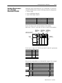
In the following 4-station example, the software looks for signals
from part-detect switches to be in correct state when the window is
ON. It monitors the up-stream switch, then die locations in pairs.
Stroke n
Window
ON
Part in the die
Upstream
Station
120V ac
or 24V dc
Alternate Channel Setup
1st Input
to B46/105
XFR mode Channel 1
Output bypassed
Stroke n +1
Stroke n +2
OFF
OFF
Window
ON
Part in transfer
Station 1
Window
ON
Part in the die
Station 2
XFRmode
Channel 1
XFRmode
Channel 2
XFRmode Input
Channel 2
XFRmode Input
Channel 3
Stroke n +3
OFF
Window
ON
Part in transfer
Station 3
XFRmode
Channel 3
XFRmode Input
Channel 4
Publication 65566.5.6 - April 1996
3–4
Determining Your DM Requirements
Static Mode (STC) Use this mode to detect that an event occurred
independent of the press stroke. When a static-mode input turns Off,
the programmed output is turned On. For example, use it to detect
end of stock.
Analog (ALG) Use this mode to verify that a signal from an analog
sensor remained within minimum and maximum limits during the
programmed window. The software declares a fault signal when it
detects the analog signal outside either limit. For example, use it to
monitor the thickness of ribbon material moving continuously.
Screen displays, covered in another chapter, show how you select any of
the previously described channel input modes.
Output Responses
for DM Channels
When the software detects a channel fault, it displays the channel
number and type of fault on a PanelView screen. The software also
sets a fault bit that you select from the following:
warning (you program the response)
stop on top (for use with Allen-Bradley C/B software)
stop now (for use with Allen-Bradley C/B software)
output by-passed, used for XFR-mode channel entry station
or when the channel is not used
When a stop command stops the press, you may program additional
machine responses, such as controlling part movement between presses.
When you select warning, you can program the activation of a sound
device, visual display, or some other means of conveying a warning.
Screen displays, covered in chapter 13, show how you select the desired
output response.
Counting Your
DM Input Channels
Publication 65566.5.6 - April 1996
Determine the number of DM input channels required for your
application so you can select the type and quantity of input modules
to process these signals. We suggest that you use Worksheet A (next
page) to do this.
Determining Your DM Requirements
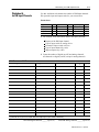
Worksheet A
for DM Input Channels
3–5
Use this worksheet to determine the number of DM input channels.
We repeat the input and output codes for your convenience.
Instructions:
Type of Channel
Code
Type of Channel
Code
Output Response
Code
Cyclic
CYC
Track
TRK
Warning
WRN
Singlepart
SGP
Transfer
XFR
Stop on Top
ST
Inposition
POS
Static
STC
Stop Now
SN
Analog
ALG
1. For each job, write down these items in the space provided:
Purpose of the DM input channel
Type of input switch or analog device
Location of input switch or device
Type of input channel (by code)
Output response (by code)
2. Count the number of digital (on/off) and analog channels.
All channels are digital (on/off) except for analog channels.
Job #
Job Name
Purpose of DM Channel
@
Type of Switch / Device
Location of Switch / Device
Chnl Type@
Output@
Enter the code for your choice of input channel and output response (from worksheet instructions).
Total DM digital channels _____ (up to 16)
Total DM analog channels _____ (up to 16)
Publication 65566.5.6 - April 1996
3–6
Determining Your DM Requirements
Notes:
Publication 65566.5.6 - April 1996
Chapter
4
Determining Your PLS
Requirements
Objectives
Operation of the
Programmable Limit
Switch (PLS)
This chapter describes the operation of the programmable limit switch
so you can determine the number of PLS channels required for your
application. We start by describing the operation of PLS output modes
so you can select them as needed.
Allen-Bradley Programmable Limit Switch software is designed to turn
outputs ON and OFF at precise crankshaft positions synchronized with
crankshaft rotation monitored with a resolver. You can preset up to 16
ON/OFF settings at angles from 0-359o. You can also turn the output
OFF with a timer.
A PLS output turns ON and OFF according to how you program it
with a PanelView data-entry screen. For example:
Turn ON a PLS Output with a:
Turn OFF a PLS Output with a:
crankshaft ON angle that you preset
crankshaft OFF angle that you preset, or
PLS timer that you preset
The output turns ON
at a preset angle.
0o
Neartop Zone
Down
stroke 90o
Zone
Up
270o stroke
Zone
The output turns
OFF at a preset
angle or time.
Bottom
180o
As a result, you can use PLS outputs to effectively control auxiliary press
machinery such as lifters, grippers blow-off valves, and inter-press
automation by programming your application-specific output responses.
You write ladder logic to initiate some action when the PLS output turns
On and/or Off.
Screen displays, covered in chapter 14, show how you enter the time
and/or angles to control PLS operation.
Publication 65566.5.6 - April 1996
4–2
Determining Your PLS Requirements
Operation of the PLS
Output With a DM Track
mode Input
Timing Diagram
The purpose of the PLS output channel when combined with a DM
input channel configured for track mode is to verify correct operation
of a programmed action. For example, you could use track mode to
verify that robot arms moved a part from one location to another and
returned to home position within the alloted time. We repeat the
track mode diagram from chapter 3.
PLS input
turns PLS
output ON
PLS input
turns PLS
output OFF
Time
Trackmode
sensor signal
must be OFF.
Sensor signal
to PLS channel
goes ON.
PLS output starts
machine motion and
trackmode timer
Trackmode sensor signal
must turn ON to indicate
completion of movement.
Trackmode
timer
times out
If trackmode sensor signal
goes ON after trackmode timer
times out, software sets a fault bit.
Time required for one press stroke
Counting Your
PLS Channels
Publication 65566.5.6 - April 1996
Determine the number of PLS output channels required for your
application so you can select the type and quantity or output modules to
process their signals. We suggest that you use Worksheet B (next page)
to do this.
Determining Your PLS Requirements
Worksheet B
for PLS Output Channels
4–3
Use this worksheet to determine the purpose and number of PLS
channels.
Instructions:
1. For each job, write down these items in the space provided:
Name of the PLS channel
What the output logic will achieve
Machine location of programmed motion
Whether PLS will use a track-mode input (Yes or No)
2. Count the number of PLS channels required.
Job #
Job Name
Name of
PLS Channel
What PLS Output Logic
Will Achieve
Machine Location
of Programmed Motion
TRK Mode?
Y/N
Total PLS channels _____ (up to 16)
Publication 65566.5.6 - April 1996
4–4
Determining Your PLS Requirements
Notes:
Publication 65566.5.6 - April 1996
Chapter
5
Setting Up System Hardware
Objectives
This chapter helps you determine system hardware requirements.
Hardware requirements depend on how you are using PLS and DM:
• as a stand-alone control system
• with Allen-Bradley Clutch/Brake control system (cat. no. 6556-SCBK)
(Available for PLS/DM are 4 output points, and up to 3 empty slots)
• with other logic
We help you:
•
•
•
•
•
select I/O modules
compute power requirements for selecting the power supply
select the size of your I/O chassis
assign slot locations to I/O modules
list I/O functions on pre-addressed worksheets
We suggest that you select your I/O modules first, because your
selection helps determine the size of the I/O chassis, power required
for I/O modules, and I/O addressing.
Selecting I/O Modules
Your selection of I/O modules to process the input and output signals
of your control system depends on:
•
•
•
•
•
•
total number of digital inputs
total number of analog inputs
voltage or current specifications of your input signals
total number of digital outputs
total number of analog outputs
voltage or current specifications of your output signals
Important: Tally your total system I/O requirements. Refer to:
• Worksheet A for DM inputs
• Worksheet B for PLS outputs
• Your count of I/O requirements for the remainder of the system
Your selection of I/O modules depends on system I/O requirements.
You may want to include spares for future growth.
Publication 65566.5.6 - April 1996
5–2
Setting Up System Hardware
With your system I/O requirements in mind, select digital I/O
modules from the following tables:
AC Input Modules
Voltage:
100120
100
120
200240
200
240
Inputs:
4
8
16
Catalog No:
1746IA4
1746IA8
1746IA16
4
8
16
1746IM4
1746IM8
1746IM16
DC Input Modules
Voltage:
1030
Sinking
(source
load)
10 30
1030
Sourcing
(sink load)
Inputs:
8
16
16
16
32
8
16
16
Catalog No:
1746IB8
1746IB16
1746IN16
1746ITB16
1746IB32
1746IV8
1746IV16
1746ITV16
Signal Delay:
typical response (8 ms)
typical response (8 ms)
ac/dc (15 ms dc) (25 ms ac)
fast response (0.5 ms typical)
typical response (3 ms)
typical response (8 ms)
typical response (8 ms)
fast response (0.5 ms typical)
32
1746IV32
typical response (3 ms)
Sinking or sourcing depends on the polarity of your dc system wiring:
Sinking (source load)
Sourcing (sink load)
IN 0
+DC
(L1 for ac)
IN 0
-DC
IN 1
(L2 for ac)
-DC
IN 1
DC
COM
AC Output & Relay Contact Modules
Voltage:
Inputs:
Catalog No:
8
1746OA8
85 265
85265
16
1746OA16
4
8
8
16
Relay
Contact
Voltage:
10 50
1050
Source
1746OW4
1746OW8
1746OX8@
1746OW16
@ Individually
VDC
+DC
10 50
1050
Sink
Inputs:
8
16
16
32
8
16
16
32
DC Output Modules
Catalog No:
Notes:
1746OB8
general purpose
1746OB16
general purpose
1746OBP16 2026 vdc, highcurrent outputs
1746OB32
lowcurrent outputs
1746OV8
general purpose
1746OV16
general purpose
1746OVP16 2026 vdc, highcurrent outputs
1746OV32
lowcurrent outputs
isolated highcurrent relay outputs
Sinking or sourcing depends on the polarity of your dc system wiring:
Output Sourcing
Output Sinking
VDC
OUT 0
+DC
Publication 65566.5.6 - April 1996
+DC
-DC
DC COM
VDC
OUT 0
CR
OUT 1
OUT 1
DC COM
VDC
OUT 0
CR
Relay Output
+DC
(L1 for ac)
CR
OUT 1
-DC
Last
OUT
-DC
(L2 for ac)
Setting Up System Hardware
5–3
Also available are these digital input/output modules:
Cat. No:
# Inputs:
Input Range:
# Outputs:
Relay Output
1746IO4
2
85132V ac
2
5256V ac
1746IO8
4
85132V ac
4
5256V ac
1746IO16
8
85132V ac
8
5256V ac
If your application requires analog I/O modules, select them from the
following table:
Cat. No:
Input Specs:
# Outputs:
Output Range
2
010V dc @
020 mA @
12 bit resolution
04095 counts
100µs response
7kHz input filter
2
020 mA
14bit resolution
2
-10 to +10V dc @
-20 to +20 mA @
12bit resolution
04095 counts
100µs response
7kHz input filter
2
-10 to +10V dc
14bit resolution
4
-10 to +10V dc @
-20 to +20 mA @
16bit resolution
"16,384 counts
60 ms response
10Hz input filter
0
n/a
2
-10 to +10V dc @
-20 to +20 mA @
16bit resolution
"16,384 counts
60 ms response
10Hz input filter
2
020 mA
14bit resolution
1746
NIO4V
2
-10 to +10V dc @
-20 to +20 mA @
16bit resolution
"16,384 counts
60 ms response
10Hz input filter
2
-10 to +10V dc
14bit resolution
1746
NO4I
0
n/a
4
020 mA
14bit resolution
1746
NO4V
0
n/a
4
-10 to +10V dc
14bit resolution
1746
FIO4I
1746
FIO4V
1746
NI4
1746
NIO4I
@
Compute Power for
Selecting a Power Supply
# Inputs:
selectable input range for each channel
Each I/O module draws specified power from the power supply.
You may compute the required power by adding up the power drawn
by each module. Then select the power supply that provides at least
that amount of power.
Look up module power ratings in the following table. All modules
have a 5V dc backplane power rating. Some also have a 24V dc
backplane power rating, so examine both ratings.
Publication 65566.5.6 - April 1996
5–4
Setting Up System Hardware
Module Type:
AC Input
DC Input
I t
AC/DC Input
Input/Output
AC Output
DC Output
Relay Contact
Output
p
SLC Processor
Important:
I/O Module:
5V
24V
IA4
IA8
IA16
IM4
IM8
IM16
IB8
IB16
ITB16
IB32
IV8
IV16
ITV16
IV32
0.035A
0.050A
0.085A
0.035A
0.050A
0.085A
0.050A
0.085A
0.085A
0.106A
0.050A
0.085A
0.085A
0.106A
0
0
0
0
0
0
0
0
0
0
0
0
0
0
IN16
0.085A
0
IO4
IO8
IO12
OA8
OA16
OB8
OB16
OBP16
OB32
OV8
OV16
OVP16
OV32
OX8
OW4
OW8
OW16
SLC 5/02
SLC 5/03
0.035A
0.060A
0.090A
0.185A
0.370A
0.135A
0.280A
0.250A
0.452A
0.135A
0.270A
0.250A
0.452A
0.085A
0.045A
0.085A
0.170A
0.350
0.500
0.025A
0.045A
0.070A
0
0
0
0
0
0
0
0
0
0
0.090A
0.045A
0.090A
0.180A
0.105
0.175
SLC 5/04
1.00A
0.200A
You must include the power requirements of the
processor and any other I/O modules in the chassis.
Select the power supply from the following table:
Line
Publication 65566.5.6 - April 1996
24V dc
Pwr Sply Cat. No:
120/240V ac
2.0A
5.0A
10.0A
5V dc
0.46A
0.96A
2.88A
1746P1
1746P2
1746P4
24Vdc
3.6A
0.87A
1746P3
Setting Up System Hardware
Hardware Requirements
for an Example
Standalone PLS/DM
5–5
Although system requirements may vary considerably, we present an
example PLS/DM system with the following hardware configuration:
• resolver input
• up to 16 DM input channels
• up to 8 PLS output channels
Use This Type of Module
Example Cat. No:
crankshaft rotation
To Monitor / Control
resolver input
Helm HN571RES
switch inputs for DM
ac digital input
1746ITV16
solenoids and relays for PLS
ac digital output
1746OA8
For the I/O chassis, the 1746-A4 holds three I/O modules.
Other sizes: 1746-A7, -A10, and -A13 (for 6, 9, and 12 I/O modules).
SLC5/03 or SLC5/04
Processor in slot 0
Resolver
input module
in slot 1
1746ITV16
input module
in slot 2
1746OA8
output module
in slot 3
1746A4
I/O Chassis
Power
Supply
For the power supply, the 1746-P1 meets the 5V and 24V requirements.
Module
5V
24V
SLC5/03
0.500A
0.175A
resolver (est.)
0.049A
0.057
1746ITV16
0.085A
0
1746OA8
0.185A
0
Total
0.819A
0.232A
Now you can assign addresses to DM and PLS channels. For example:
Slot #
Chnl #
Function / Purpose
Address
1
n/a
resolver input
I:1 (word)
2
1
2
3
DM cyclic mode, part passed check point 1
DM track mode, for robot arm
DM singlepartdetect, part in die zone 1
I:2/0 (bit)
I:2/1
I:2/2
3
1
2
3
PLS output, activate surface lub for die zone 1
PLS output for track mode, start robot arm
PLS output, eject part from die zone 1
O:3/0 (bit)
O:3/1
O:3/2
Publication 65566.5.6 - April 1996
5–6
Setting Up System Hardware
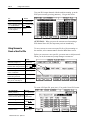
Hardware Requirements
for an Example PLS/DM
and Clutch/Brake System
When combined with clutch/brake control software (cat. no. 6556-SCB),
the minimum size I/O chassis is nine I/O slots (1746-A10) and slot
locations for PLS/DM are pre-assigned as follows:
Slot #:
Contains This Module:
1
resolver input (existing)
signals from the resolver
5
1746ITV16
up to 16 DM inputs
7
1746IO12 (existing)
up to 4 PLS outputs
Resolver
input module
in slot 1
SLC5/03 or SLC5/04
Processor in slot 0
To Process:
1746ITV16
input module
in slot 5
Existing
1746IO12
I/O module
in slot 7
1746A10
I/O Chassis
Power
Supply
The largest available I/O chassis (cat. no. 1746-A13) provides 12 I/O
slots. If needed, you may expand to 30 I/O slots by adding more chassis.
Add up the power drawn by all modules including the SLC processor
in the I/O chassis, and select the power supply accordingly.
Now you can assign addresses to DM and PLS channels. The preassigned
outputs for PLS in slot 7 are outputs 4-7. For example:
Slot #
Chnl #
1
n/a
resolver input
I:1 (word)
5
1
2
3
4
5
DM cyclic mode, part past check point 1
DM track mode, for robot arm
DM singlepartdetect, part in die zone 1
DM cyclic mode, part past check point 2
DM singlepartdetect, part in die zone 2
I:5/0 (bit)
I:5/1
I:5/2
I:5/3
I:5/4
1
2
3
PLS output, activate surface lub for die zone 1
PLS output for track mode, start robot arm
PLS output, eject part from die zone 1
O:7/2 (bit)
O:7/3
O:7/4
4
PLS output, eject part from die zone 2
O:7/5
7
Function / Purpose
Address
If you need to need more I/O capacity and use the 12-slot I/O chassis,
addresses for channels in slots 10, 11, and 12 will be in the format:
Slot #
10
Publication 65566.5.6 - April 1996
Address
I:10/xx (bit)
Slot #
11
Address
I:11/xx (bit)
Slot #
12
Address
I:12/xx (bit)
Setting Up System Hardware
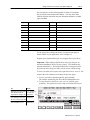
Hardware Requirements
for an Example PLS/DM
with Other Logic
5–7
If your application required PLS/DM with additional logic for machine
automation, the control system would depend on the number and type of
I/O modules required in addition to those for the stand-alone PLS/DM
previously described. For example, suppose your total system required:
•
•
•
•
•
•
•
resolver input
15 DM digital input channels
1 DM analog input channel
9 PLS output channels
1 analog input and 2 analog outputs (system)
12 other switch inputs
7 other relay outputs
You could select the following type and quantity of I/O modules:
To Monitor / Control
With Module Qty & Type
Example Cat. No:
crankshaft rotation
1 resolver input
unspecified
switch inputs
2 16point ac digital input
1746ITV16
solenoids and relays
2 8point ac digital output
1746OX8
analog inputs and outputs
1 analog I/O
1746FIO4I
For the I/O chassis, the 1746-A7 holds six I/O modules plus processor.
Resolver
1746ITV16
input module input modules
in slot 1
in slots 2 and 3
1746FIO4I
analog I/O
module in slot 4
1746OX8
output modules
in slots 5 and 6
SLC5/03 or SLC5/04
Processor in slot 0
Power
Supply
1746A7
I/O Chassis
For the power supply, the 1746-P2 is required for the 24V requirement.
Module
5V
24V
1 SLC5/04
1.000A
0.200A
1 resolver (est.)
0.300A
0
2 1746ITV16
0.170A
0
2 1746OX8
0.170A
0.180
1 FIO4I
0.055A
0.195A
1.695
0.575
Total
Publication 65566.5.6 - April 1996
5–8
Setting Up System Hardware
Now you can assign addresses to DM and PLS channels and to your
system I/O. For example (with this total I/O requirement):
•
•
•
•
•
•
•
resolver input
15 DM digital input channels
1 DM analog input channel
12 other switch inputs (non-DM/PLS functions)
1 analog input and 2 analog outputs (non-DM/PLS functions)
9 PLS output channels
7 other relay outputs (non-DM/PLS functions)
Slot #
Chnl #
1
n/a
resolver input
I:1 (word)
1
2
:
15
n/a
n/a
:
n/a
n/a
16
n/a
n/a
n/a
DM input 1
DM input 2
:
DM input 15
spare
other switch input 1
:
other switch input 12 (last)
four spare inputs
DM analog input channel
system analog input
system analog output 1
system analog output 2
I:2/0 (bit)
I:2/1
:
I:2/14
1
PLS output 1
O:5/0 (bit)
2
PLS output 2
O:5/1
:
:
:
8
PLS output 8
O:5/7
9
n/a
:
n/a
PLS output 9 (last)
system output 1
:
system output 7 (last)
O:6/0 (bit)
O:6/1
:
O6:7
2
3
4
5
6
Publication 65566.5.6 - April 1996
Function / Purpose
(nonDM/PLS function)
(nonDM/PLS function)
(nonDM/PLS function)
(nonDM/PLS function)
(nonDM/PLS function)
(nonDM/PLS function)
(nonDM/PLS function)
Address
I:3/0
:
I:3/11
I:3/1215
I:4.0 (word)
I:4.1
O:4.0
O:4.1
Setting Up System Hardware
Considerations When
Setting Up Analog
Channels
5–9
DM software lets you configure any channel for digital or analog
operation and assign an analog address of your choice to any channel.
You match the analog address to the analog channel in chapter 8.
You decide how many analog channels you need, from none up to 16.
Whether the channel can process analog data depends on whether you:
• assign a slot for an analog input module
• program the transfer of analog data to the pre-assigned area of the
data table reserved for DM analog inputs (chapter 8)
If your application requires only a few analog channels, we suggest
that you number them backwards from channel 16 for easier record
keeping.
You may want to set up some analog channels now, even if your
current application does not require them.
Important: If not set up but required later, you must re-configure
your I/O hardware (this chapter) and software (chapter 8). If set up
but not used, install the analog module in your assigned I/O slot and
program the transfer of analog data. (Your ladder logic cannot
address an empty module slot without faulting the processor, unless
you disable the slot.)
List I/O Functions on
Preaddressed
Worksheets
The DM/PLS software uses pre-assigned files in the data table to
store active DM inputs and PLS outputs. Because we give you the
flexibility to place I/O modules in any slot location, you must write
ladder logic to move I/O signals between I/O image table addresses
(based on slot locations) and pre-assigned files used by the DM/PLS
software.
We suggest that you use our pre-addressed worksheets to accurately
record your hardware-based I/O image table addresses. Worksheets
will be helpful later when writing ladder logic (chapters 8-10).
Publication 65566.5.6 - April 1996
5–10
Setting Up System Hardware
Worksheet C for DM Inputs
& I/O Addresses
Job #
Chnl #
Slot # ____ / Bit #
Name
DM Input Function / Purpose
Address
1
I:__/__
2
I:__/__
3
I:__/__
4
I:__/__
5
I:__/__
6
I:__/__
7
I:__/__
8
I:__/__
9
I:__/__
10
I:__/__
11
I:__/__
12
I:__/__
13
I:__/__
14
I:__/__
15
I:__/__
16
I:__/__
Publication 65566.5.6 - April 1996
Setting Up System Hardware
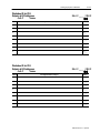
Worksheet D for PLS
Outputs & I/O Addresses
Job #
5–11
Slot # ____ / Bit #
Name
Chnl #
PLS Output Function / Purpose
Address
1
O:__/__
2
O:__/__
3
O:__/__
4
O:__/__
5
O:__/__
6
O:__/__
7
O:__/__
8
O:__/__
Worksheet D for PLS
Outputs & I/O Addresses
Job #
Chnl #
Slot # ____ / Bit #
Name
PLS Output Function / Purpose
Address
1
O:__/__
2
O:__/__
3
O:__/__
4
O:__/__
5
O:__/__
6
O:__/__
7
O:__/__
8
O:__/__
Publication 65566.5.6 - April 1996
5–12
Setting Up System Hardware
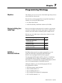
Worksheet E for Other
Inputs & I/O Addresses
Job #
Slot # ____ / Bit #
Name
Chnl #
Input Function / Purpose
Address
1
I:__/__
2
I:__/__
3
I:__/__
4
I:__/__
5
I:__/4__
6
I:__/__
7
I:__/__
8
I:__/__
9
I:__/__
10
I:__/__
11
I:__/__
12
I:__/__
13
I:__/__
14
I:__/__
15
I:__/__
16
I:__/__
Publication 65566.5.6 - April 1996
Setting Up System Hardware
Worksheet F for Other
Outputs & I/O Addresses
Job #
Chnl #
5–13
Slot # ____ / Bit #
Name
Output Function / Purpose
Address
1
O:__/__
2
O:__/__
3
O:__/__
4
O:__/__
5
O:__/__
6
O:__/__
7
O:__/__
8
O:__/__
9
O:__/__
10
O:__/__
11
O:__/__
12
O:__/__
13
O:__/__
14
O:__/__
15
O:__/__
16
O:__/__
Publication 65566.5.6 - April 1996
5–14
Setting Up System Hardware
Notes:
Publication 65566.5.6 - April 1996
Chapter
6
Installing Your Software
Chapter Objective
How the Installation of
PLD/DM Software Affects
Your Hard Drive
We show you how to install PLS/DM diskettes on you conputer’s
hard drive.
When you install PLS/DM software, it:
•
•
•
•
creates a work directory
decompresses PLS/DM software files
copies them onto hard disk
creates a program group named Allen-Bradley if not already created
It also creates the following directories and subdirectories for storing
associated ladder program files.
C:\
IPDS
ARCH
LIS
AB
SLC500
SLC500
APPBLDR
ARCHIVE
MODULE
PBWIN
PLS/DM software uses approximately 3 MByte of disk storage.
Installing
PLS/DM Software
The Install program, located on the distribution diskette, copies the
PLS/DM software files onto your hard disk.
Important: Install APS software if you have not already done so.
To install PLS/DM software:
1. Place the PLS/DM software diskette in the computer system’s
floppy disk drive.
2. Start Windows by typing win ENTER at the C:\ prompt:.
3. From the File menu, select Run.
The Run dialog box appears.
Publication 65566.5.6 - April 1996
6–2
Installing Your Software
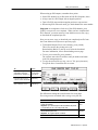
4. In the command line buffer, type: a:\setup and press ENTER .
(The letter a represents the disk drive into which you placed the
PLS/DM software diskette in step 1 above.)
NOTE: The PLS/DM Installation Program screen appears
and installation begins.
Follow instructions on the screen for steps 5-8.
(We show the steps for a first-time installation.)
Publication 65566.5.6 - April 1996
Step: When you see this prompt:
Do this:
5
Please enter the location
for SLC Ladder Files
Click on OK,
or type in a new location
6
Please enter the location for
SLC ASCII Files.
Click on OK.
7
Please enter the location for
PanelBuilder Files.
Click on OK.
8
Installation Is Complete
Click on OK.
Chapter
7
Programming Strategy
Objectives
This chapter gives you an overview of the ladder logic that you must
write to make the system work.
We also show you how program files are organized depending on
whether you are using PLS/DM software:
• as a stand–alone control
• with Allen–Bradley clutch/brake software (6556-SCB)
Strategy for Writing Your
Ladder Logic
Because of the flexible arrangement of I/O with SLC-500 products,
you must write ladder logic to make input signals available to the
software, and send software-controlled signals to output devices.
We help you write ladder logic to achieve these objectives in the
following chapters:
PLS/DM as
Standalone Software
We Cover these Programming Objectives:
in:
• Move DM input signals into the data table
• Program other software inputs
• Program DM outputs
chapter 8
• Move resolver input signals into the data table
• Program PLS outputs
chapter 9
• Move counter input signals into the data table
• Program counter outputs
chapter 10
• Set up parameters to compensate for press speed
chapter 11
PLS/DM software provides you with a program file to use for
writing the ladder logic required PLS and/or DM inputs.
We have reserved program file PF14 for this purpose.
You may program PLS outputs in PF14. However, if combining
your PLS/DM software with the Clutch/Brake system (cat. no.
6556-SCB), we recommend that you program PLS outputs in FP15,
reserved for programming the clutch/brake interface.
Although available to you, the remaining program files are
pre-programmed as follows:
•
•
•
•
•
PF2 for the master control program
PF10 for DM channels 1-8
PF11 for DM channels 9-16
PF12 for PanelView and part-file management
PF31 for PLS channels 1-16
Publication 65566.5.6 - April 1996
7–2
Programming Strategy
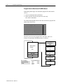
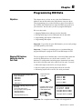
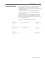
Program Scan for Standalone PLS/DM Software
Subdividing ladder logic into subroutine program files has benefits
such as:
• easier to understand and troubleshoot
• faster scan time because the processor scans only
the “called” subroutines
We subdivided PLS/DM software into these subroutine program files
(abbreviated with PFxx):
This programming function:
Uses:
Master Control Program
PF2
DM Channels 18
PF10
DM Channels 916
PF11
PanelView and Partfile Management
PF12
PLS/DM Inputs and Outputs that you program
PF14
PLS Channels 116
PF31
The SLC processor scans program files, data table, and I/O as
follows for stand-alone PLS/DM software as follows:
Your PLS/DM
Inputs/Outputs
PF14
Master Control
Program
DM Channels 18
PF2
PF10
DM Channels 916
Data Table
I/O
Files created for
your programming:
- PF14
Publication 65566.5.6 - April 1996
Preprogrammed files:
- PF2
- PF12
- PF10
- PF31
- PF11
PF11
PanelView and Part
file Management
PF12
PLS Channels 116
PF31
Programming Strategy
PLS/DM Used with
Clutch/Brake Software
7–3
Clutch/brake software has its own set of subroutine program files.
When you combine PLS/DM software with clutch/brake software,
we recommend that you use two program files for writing the ladder
logic required to suit your application:
• for PLS and/or DM inputs, use PF14
• for PLS and/or DM outputs, use PF15
PF15 is a file that shares your PLS/DM outputs and your clutch/brake
interface logic. This program file resides in both of the processors that
control the clutch/brake mechanism. We recommend that you add
your PLS/DM logic to PF15 in only one processor, and refer you the
clutch/brake design manual for more information.
The remainder of program files are pre-programmed.
We recommend that you do not edit them.
•
•
•
•
•
•
•
PF2 for the master control program
PF3 auxiliary control program (set up by ApplicationBuilder)
PF10 for DM channels 1-8
PF11 for DM channels 9-16
PF12 for PanelView and part-file management
PF16 for the clutch/brake code
PF31 for PLS channels 1-16
Program Scan for Combined PLS/DM and C/B Software
We subdivided PLS/DM and C/B software into these subroutine
program files (PFxx):
This programming function:
Uses:
Master Control Program
PF2
Auxiliary Control Program
PF3
DM Channels 18
PF10
DM Channels 916
PF11
PanelView and Partfile Management
PF12
Your Inputs to PLS/DM
PF14
Your PLS/DM Outputs and C/B Interface
PF15
C/B Code
PF16
PLS Channels 116
PF31
Publication 65566.5.6 - April 1996
7–4
Programming Strategy
The SLC processor scans program files, data table, and I/O as
follows for the combined PLS/DM and C/B software:
Factoryconfigured
Master Control
Program
PF2
Data Table
I/O
Auxiliary Control
Program
PF3
Your Inputs
to PLS/DM
PF14
DM Channels 18
PF10
DM Channels 916
Files created for
your programming:
- PF14
- PF15
Factoryprogrammed files:
- PF2
- PF12
- PF10
- PF31
- PF11
Processors A and B scan the same
program files. We suggest that you
minimize the ladder logic in processor
B for a faster scan time and a faster
system response.
Publication 65566.5.6 - April 1996
PF11
PanelView and Part
file Management
PF12
PLS Channels 116
PF31
Your PLS/DM Outputs
and C/B Inputs
PF15
Factoryconfigured
Clutch/Brake Code
PF16
Subroutine PFs
that you program
to control optional
auxiliary functions
Chapter
8
Programming DM Data
Objectives
This chapter shows you how to move data from DM hardware
addresses into the data table so the DM software can access them.
This programming gives you the flexibility to place I/O modules in
any available slot location and use inputs for DM from anywhere in
your controller. We also show you how to program DM outputs.
We cover these tasks:
•
•
•
•
Mapping DM hardware addresses into the data table
Writing ladder logic to move DM inputs into the data table
Programming other inputs to DM software
Programming DM outputs
Important: If you allow for spare DM channels, you can easily enlarge
your DM capability in the future.
Important: To improve system thru-put, we recommend that you
program DM inputs in program file PF14 and DM outputs in PF15.
Mapping DM Hardware
Addresses into the
Data Table
The pre-assigned areas of the data table, reserved for DM signals and
accessed by DM software, are a bit file and a word file. Your
hardware I/O configuration (including spares) determines how many
bits of the bit file and words of the word file will be used. You store:
• DM switch inputs in the bit file, one bit per channel
• Resolver inputs (press position and speed) in the word file
• DM analog inputs in the word file, one word per channel
Your hardware (I/O image table) bit addresses
for up to 16 channels
- DM channel 1
- DM channel 2
- DM channel 3
:
:
- DM channel 16
Your hardware (I/O image table) word addresses
(as needed)
- press position (from resolver)
- press speed (from resolver) (optional)
- analog input channel 1
- analog input channel 2
:
:
- analog input channel (up to 16)
Program the transfer
of all 16 bits
Program the transfer of words
(dependent on slots assigned
to analog input modules)
Data table bit file:
- channel 1 at B46/0
- channel 2 at B46/1
- channel 3 at B46/2
:
:
- channel 16 at B46/15
Data table word file:
- press position at N61:254
- press speed at
N61:255
- analog input channel 1 at N45:0
- analog input channel 2 at N45:1
:
:
- analog input channel 16 at N45:15
Important: For a complete data table map, refer to appendix A.
Publication 65566.5.6 - April 1996
8–2
Programming DM Data
Writing Ladder Logic to
Move DM Inputs into the
Data Table
You can move DM data with Examine/Execute, Copy, and/or Move
instructions. The bits and/or words of I/O image table to be moved
and their addresses depend on the hardware I/O configuration that
you determined in chapter 5. For example:
From hardware (I/O image) addresses
Bit/Word Description:
Slot:
Source Address:
To PLS data table
Destination Address:
resolver (press position)
resolver (press speed)
1
I:1.1(1)
I:1.2(2)
16 bits for channels 116
5
I:5/0, I5/1, . . . I:5/15
B46/0, B46/1, . . B46/15
I:10.1
I:10.2
I:10.3, I:10.4, . . .
N45:0
N45:1
up to N45:15
analog input 1
analog input 2
analog input as needed
(1) when
10
I:1.3(3)
N61:254
N61:255
using an AMCI or Helm resolver input module in Slot 1 of the I/O chassis
(2) when
using an AMCI series 1500 resolver input module in slot 1
(3) when
using a Helm resolver input module in slot 1
We pre-programmed Copy (COP), Move (MOV), and Examine/Execute
(XIC/OTE) instructions in PF14 to move the data into the pre-assigned
DM data table. Edit them to suit your application.
Important: Edit these instructions with the addresses of your I/O.
Refer to hardware addresses that you wrote down on Worksheets in
chapter 5.
Important: Do not write ladder logic addressed from empty slot
locations. The processor will fault unless you disable the slot.
Rung 14:0
| Move analog data for 4 channels
N45:0 =
|
|
Channel 1
|
|
analog input
|
|
+COP–––––––––––––––+ |
|–––––––––––––––––––––––––––––––––––––––––––––––––––––––––+COPY FILE
+–|
|
|Source
I:10.1| |
|
|Dest
#N45:0| |
|
|Length
4| |
|
+––––––––––––––––––+ |
Rung 14:1
| Move resolver position and speed inputs
N61:254 =
|
| (Addressed for a Helm resolver module)
Press Position
|
|
(customer map)
|
|
+MOV–––––––––––––––+
|
|–––––––––––––––––––––––––––––––––––––––––––––––––––––+–+MOVE
+–+–|
|
| |Source
I:1.1| | |
|
| |
0| | |
|
| |Dest
N61:254| | |
|
| |
0| | |
|
| +––––––––––––––––––+ | |
|
|
Press Speed
| |
|
|
(customer map) | |
|
| +MOV–––––––––––––––+ | |
|
+–+MOVE
+–+ |
|
|Source
I:1.3|
|
|
|
0|
|
|
|Dest
N61:255|
|
|
|
0|
|
|
+––––––––––––––––––+
|
Publication 65566.5.6 - April 1996
Programming DM Data
8–3
Rung 14:2
| Move DM input channel bit status
|
| CHANNEL 1 INPUT |
CHANNEL 1 INPUT |
| (customer Map) |
(customer Map) |
|
I:5
B46
|
|––––] [–––––––––––––––––––––––––––––––––––––––––––––––––––––––––––––––( )–––––|
|
0
0
|
Rung 14:3
| Move DM input channel bit status
|
| CHANNEL 2 INPUT |
CHANNEL 2 INPUT |
| (customer Map
|
(customer Map) |
|
I:5
B46
|
|––––] [–––––––––––––––––––––––––––––––––––––––––––––––––––––––––––––––( )–––––|
|
1
1
|
Up To
Rung 14:17
| Move DM input channel bit status
|
| CHANNEL 16 INPUT |
CHANNEL 16 INPUT |
| (customer Map)
|
(customer Map) |
|
I:5
B46
|
|––––] [–––––––––––––––––––––––––––––––––––––––––––––––––––––––––––––––( )–––––|
|
15
15
|
Programming Other
Software Inputs
We present the following control bits that you can program in PF14
for the desired response. Some are required. Others are optional.
For DM Exclusively
Use this Bit:
at Addr:
To:
XFRmode
1st input
B46:105
program an upstream 1st input
(alternative to 1st channel with bypassed output)
XFRmode
Resume Operation
B46:106
reinitialize memory with snapshot" logic status
(Use with separate restart logic.)
Fault Reset
B46:101
reset fault logic and message after clearing a fault
(Required programming.)
Overwrite
Active File
B46:107
download a part file that overwrites active job
(Recognize consequences and take precautions.)
Enable Edits
B46:100
allow editing of a stored or active part file
(For password access)
For DM and/or PLS
These five bits are pre-programmed in PF14. We suggest that you:
• modify each rung by adding input conditions according to your
application requirements
• deleting the entire rung if that function is not required
Important: Edit these instructions with the addresses of your I/O.
Refer to hardware addresses that you wrote down on worksheets in
chapter 5.
Important: Do not write ladder logic to MOVE words from empty
slot locations. The processor will fault unless you disable the slot.
Publication 65566.5.6 - April 1996
8–4
Programming DM Data
For example:
Rung 14:18
| Correct password enables edits.
|
| Password comes into N61:251 from PanelView. N61:253 contains master password.|
|
Enable Edits |
|
(customer Map)|
| +EQU–––––––––––––––+
B46
|
|–+EQUAL
+–––––––––––––––––––––––––––––––––––––––––––––––––( )–––––|
| |Source A
N61:251|
100
|
| |
1234|
|
| |Source B
N61:253|
|
| |
1234|
|
| +––––––––––––––––––+
|
Rung 14:19
| Reset Fault
|
Reset Fault
|
| (customer map |
(customer map)|
|
Panel PB
B46
|
|––––] [–––––––––––––––––––––––––––––––––––––––––––––––––––––––––––––––( )–––––|
|
xx
101
|
Rung 14:20
| Counter 1 Input |
Counter 1 Input |
| (customer map) |
(customer map) |
| Limit Switch
B46
|
|––––] [–––––––––––––––––––––––––––––––––––––––––––––––––––––––––––––––( )–––––|
|
xx
102
|
Rung 14:21
| Counter 2 Input |
|
| Press Strokes |
Counter 2 Input |
| (customer map) |
(customer Map) |
| +GEQ–––––––––––––––––+
B46
|
|–+GRTR THAN OR EQUAL +–––––––––––––––––––––––––––––––––––––––––––––––( )–––––|
| |Source A
I:1.1 |
103
|
| |
|
|
| |Source B
190 |
|
| |
|
|
| +––––––––––––––––––––+
|
Rung 14:22
| XFR mode
|
XFR mode
|
| initial input |
initial input |
| (customer map)|
(customer map)|
| Limit Switch
B46
|
|––––] [–––––––––––––––––––––––––––––––––––––––––––––––––––––––––––––––( )–––––|
|
xx
105
|
Rung 14:23
| Resume Operation|
Resume Operation|
| (customer map) |
(customer map)|
| Panel PB
B46
|
|––––] [–––––––––––––––––––––––––––––––––––––––––––––––––––––––––––––––( )–––––|
|
xx
106
|
Rung 14:24
| Overwrite
|
Overwrite
|
| Active File
|
Active File |
| (customer map)|
(customer map |
| Keyswitch
B46
|
|––––] [–––––––––––––––––––––––––––––––––––––––––––––––––––––––––––––––( )–––––|
|
xx
107
|
Publication 65566.5.6 - April 1996
Programming DM Data
Programming DM Outputs
8–5
When you set up the operation of your channels with software screen
displays (chapter 13), you determine how you want each DM
channel output to respond to a detected fault. Channel responses and
corresponding fault bits are:
• stop now bit B47/2
• stop on top bit B47/3
• warning bit B47/4
(for use with clutch/brake control)
(for use with clutch/brake control)
Write your ladder logic to examine each of the three types of fault
bits that you selected for your DM output channels. Our examples
show the programming of clutch/brake interface bits Permit Run and
Top Stop, as well as the Warning.
Program your output responses in program file PF15.
Rung 15:25
| Stop Now
|
| Other conditions for |
Permit Run |
| (customer map)|
| stopping the press
|
(customer map)|
|
B47
B151
|
|––––]/[–––––––––––––––––––] [––]/[––] [–––––––––––––––––––––––––––––––( )–––––|
|
2
4
|
Rung 15:26
| Stop on Top |
| Other conditions for |
Top Stop |
| (customer map)|
| stopping the press
|
(customer map)|
|
B47
B151
|
|––––]/[–––––––––––––––––––] [––]/[––] [–––––––––––––––––––––––––––––––( )–––––|
|
3
7
|
Rung 15:27
| Warning
|
Audible Device |
| (customer map)|
(customer map)|
|
B47
O:10
|
|––––] [–––––––––––––––––––––––––––––––––––––––––––––––––––––––––––––––( )–––––|
|
4
xx
|
Publication 65566.5.6 - April 1996
8–6
Programming DM Data
Notes:
Publication 65566.5.6 - April 1996
Chapter
9
Programming PLS Data
Objectives
This chapter shows you how to move data from the resolver input
module into the data table so the PLS software can access it. We also
show you how to move output signals from the data table to hardware
addresses. This programming gives you the flexibility to place I/O
modules in any available slot location and send PLS outputs to
anywhere in your controller.
We cover these tasks:
•
•
•
•
Mapping resolver inputs into the data table
Writing ladder logic to move resolver inputs into the data table
Mapping PLS outputs to hardware addresses
Programming PLS outputs
Important: To improve system thru-put, we recommend that you
program PLS inputs (press position and speed) in program file PF14
and PLS outputs in PF15.
Mapping Resolver Inputs
into the Data Table
Two data table words are reserved for resolver input signals. They are
the same for PLS and DM software. If you programmed them in
chapter 8 for DM, you need not program them again.
Program the transfer of two
resolver input words
Your hardware (I/O image table) word addresses
- press position (from resolver)
- press speed (from resolver)
2 data table words:
- press position at N61:254
- press speed at N61:255
Important: For a complete data table map, refer to appendix A.
Writing Ladder Logic to
Move Resolver Inputs
into the Data Table
You can program the transfer of resolver input signals with a File Move
(MOV) instruction. The words of I/O image table to be moved and their
addresses depend on the slot location of the resolver input module.
For example:
From hardware (I/O image) addresses
Word Description:
resolver (press position)
resolver (press speed)
Slot:
1
Source Address:
I:1.1(1)
I:1.2(2)
I:1.3(3)
To PLS data table
Destination Address:
N61:254
N61:255
(1) when
using an AMCI or Helm resolver input module in slot 1 of the I/O chassis
(2) when
using an AMCI series 1500 resolver input module in slot 1
(3) when
using a Helm resolver input module in slot 1
Publication 65566.5.6 - April 1996
9–2
Programming PLS Data
We pre-programmed Move (MOV) instructions in PF14 to move the
data into the pre-assigned data table area (see below).
Important: If you have not already done so for DM (chapter 8), edit
these instructions with the addresses of your I/O. Refer to hardware
addresses that you wrote down on your Worksheet in chapter 5.
Important: Do not write ladder logic to MOVE words from empty
slot locations. The processor will fault unless you disable the slot.
Rung 14:1
| Move resolver position and speed inputs
N61:254 =
|
| (Addressed for a Helm resolver module)
Press Position
|
|
(customer map)
|
|
+MOV–––––––––––––––+
|
|–––––––––––––––––––––––––––––––––––––––––––––––––––––+–+MOVE
+–+–|
|
| |Source
I:1.1| | |
|
| |
0| | |
|
| |Dest
N61:254| | |
|
| |
0| | |
|
| +––––––––––––––––––+ | |
|
|
Press Speed
| |
|
|
(customer map) | |
|
| +MOV–––––––––––––––+ | |
|
+–+MOVE
+–+ |
|
|Source
I:1.3|
|
|
|
0|
|
|
|Dest
N61:255|
|
|
|
0|
|
|
+––––––––––––––––––+
|
Mapping PLS Outputs to
Hardware Addresses
Data table bit file for PLS outputs:
- PLS channel 1 output at B146/0
- PLS channel 2 output at B146/1
- PLS channel 3 output at B146/2
up to
- PLS channel 16 output at B146/15
Programming PLS Outputs
You can map the pre-assigned area of the data table, reserved for
PLS channel outputs, to hardware addresses in the I/O image table.
This lets you match PLS channel outputs to the output points of the
one or more output modules in slot locations of your choice.
For example:
Program the transfer
of PLS output bits
When programming the transfer of PLS output bits to your hardware
addresses, you must first have determined the slot location(s) and
number of output points (terminals) of your assigned PLS outputs.
They determine your destination hardware addresses.
From PLS data table
XIC Address:
Publication 65566.5.6 - April 1996
Your hardware (I/O image table) slot/point addresses
- output point 1
- output point 2
- output point 3
for designated slot locations
up to
- output point 16
To hardware (I/O image) addresses
To this Module:
in Slot:
B146.0 (move bits 03)
existing 1746OA8
output module
7
B146.0 (move bits 415)
new 1746OA16
output module
10
with OTE Addresses:
O:7/0 - O:7/3
O:10/0 - O:10/11
Programming PLS Data
9–3
Program XIC/OTE instructions in PF15 to move PLS outputs from the
pre-assigned data table area to hardware addresses, (see below).
Important: Edit these instructions with the addresses of your I/O.
Refer to hardware addresses that you wrote down on a Worksheet in
chapter 5.
Important: Do not write ladder logic addressed to empty slot
locations. The processor will fault unless you disable the slot.
Rung 15:28
| PLS Channel 1 |
PLS Output 1 |
| (customer map) |
(customer map)|
|
B146
O:7
|
|––––] [–––––––––––––––––––––––––––––––––––––––––––––––––––––––––––––––( )–––––|
|
0
0
|
Rung 15:29
| PLS Channel 2 |
PLS Output 2 |
| (customer map) |
(customer map)|
|
B146
O:7
|
|––––] [–––––––––––––––––––––––––––––––––––––––––––––––––––––––––––––––( )–––––|
|
1
1
|
Up To
Rung 15:31
| PLS Channel 4 |
PLS Output 4 |
| (customer map) |
(customer map)|
|
B146
O:7
|
|––––] [–––––––––––––––––––––––––––––––––––––––––––––––––––––––––––––––( )–––––|
|
3
3
|
Rung 15:32
| PLS Channel 5 |
PLS Output 5 |
| (customer map) |
(customer map)|
|
B146
O:10
|
|––––] [–––––––––––––––––––––––––––––––––––––––––––––––––––––––––––––––( )–––––|
|
4
0
|
Rung 15:33
| PLS Channel 6 |
PLS Output 6 |
| (customer map) |
(customer map)|
|
B146
O:10
|
|––––] [–––––––––––––––––––––––––––––––––––––––––––––––––––––––––––––––( )–––––|
|
5
1
|
Up To
Rung 15:43
| PLS Channel 16|
PLS Output 16|
| (customer map) |
(customer map)|
|
B146
O:10
|
|––––] [–––––––––––––––––––––––––––––––––––––––––––––––––––––––––––––––( )–––––|
|
15
11
|
Publication 65566.5.6 - April 1996
9–4
Programming PLS Data
Notes:
Publication 65566.5.6 - April 1996
Chapter
10
Programming Your Counters
Objectives
This chapter shows you how to program the two counters included in
the PLS/DM software. We cover these tasks:
•
•
•
•
Mapping counter inputs into the data table
Writing ladder logic to move counter inputs into the data table
Mapping counter outputs to hardware addresses
Programming counter outputs
Important: To improve system thru-put, we recommend that you
program PLS inputs in program file PF14 and PLS outputs in PF15.
Mapping Counter Inputs
into the Data Table
Two data table bits are reserved for incrementing your counters.
Each time a counter input switch closes, the counter accumulated
value increments by one count.
Your hardware (I/O image table) bit addresses
- switch input for counter 1
- switch input for counter 2
Program the transfer of
two input bits
2 data table bits:
- counter 1 input at B46/102
- counter 2 input at B46/103
Important: For a complete data table map, refer to appendix A.
Writing Ladder Logic to
Move Counter Inputs
into the Data Table
You can transfer counter input signals into the data table with
Examine/Execute instructions. The bits of I/O image table to be
transferred and their addresses depend on the slot location and input
points of the input module to which counter switch inputs are connected.
For example:
From hardware (I/O image) addresses
Bit Description:
Counter 1 Input Bit
Counter 2 input Bit
Slot:
5
To counter data table
XIC (Source) Address:
OTE (Destination) Address:
I:5/14
B46/102
I:5/15
B46/103
We pre-programmed instructions in PF14 to move counter inputs into
the pre-assigned data table area (see below).
Important: If you have not already done so in chapter 8 for DM,
edit these instructions with the addresses of your I/O. Refer to
hardware addresses that you wrote down on a Worksheet in chapter 5.
Important: Do not write ladder logic addressed from empty slot
locations. The processor will fault unless you disable the slot.
Publication 65566.5.6 - April 1996
10–2
Programming Your Counters
Rung 14:20
| Counter 1 Input |
Counter 1 Input |
| (customer map) |
(customer map) |
| Limit Switch
B46
|
|––––] [–––––––––––––––––––––––––––––––––––––––––––––––––––––––––––––––( )–––––|
|
xx
102
|
Rung 14:21
| Counter 2 Input |
|
| Press Strokes |
Counter 2 Input |
| (customer map) |
(customer Map) |
| +GEQ–––––––––––––––––+
B46
|
|–+GRTR THAN OR EQUAL +–––––––––––––––––––––––––––––––––––––––––––––––( )–––––|
| |Source A
I:1.1 |
103
|
| |
|
|
| |Source B
190 |
|
| |
|
|
| +––––––––––––––––––––+
|
Mapping Counter Outputs
to Hardware Addresses
Counter DN bits:
- Counter 1 DN bit at B47/0
- Counter 2 DN bit at B47/1
Programming
Counter Outputs
When the counter accumulated value reaches the preset value set by a
machine operator, the counter sets a done bit (DN). You program it to
implement a response suitable to your application. Your logic can
initiate some logical function and/or activate an output device. If
activating an output device, you can map the DN bit to to the output
point of an output module in a slot location of your choice.
For example:
Program the transfer
of 2 counter DN bits
Your hardware (I/O image table) slot/point addresses
- output point for counter 1
for a designated
- output point for counter 2
slot location
The use of your counter is application specific. If using it to activate
an output device, your ladder logic could include rungs similar to the
following example. We suggest that you program this in PF15.
Counter DN bits:
XIC (Source) Address:
B46/102 (Counter 1 DN Bit)
B46/103 (Counter 2 DN Bit)
To hardware (I/O image) addresses:
Slot:
10
OTE (Destination) Address:
O:10/0
O:10/1
Important: Edit these instructions with the addresses of your I/O.
Refer to hardware addresses that you wrote down on a Worksheet in
chapter 5.
Rung 14:41
| Counter 1 DN |
Output Device |
|
B47
O:10
|
|––––] [–––––––––––––––––––––––––––––––––––––––––––––––––––––––––––––––( )–––––|
|
0
0
|
Rung 14:42
| Counter 2 DN |
Output Device |
|
B47
O:10
|
|––––] [–––––––––––––––––––––––––––––––––––––––––––––––––––––––––––––––( )–––––|
|
1
1
|
Publication 65566.5.6 - April 1996
Chapter
11
Setting Up a Password and
Compensating for Press Speed
Objectives
This chapter describes two unrelated topics because you set them up
in a similar manner with your programming terminal.
• Master Password (for maintaining authorized access)
• What it is, and how to set it up
• Press speed compensation (for a variable-speed press)
• What it is, and when to use it
• How does it work?
• How do you set it up?
Master Password:
What It Is, and
How to Set It Up
Pressspeed
Compensation:
What It Is, and
When to Use It
The master password is a 4-digit number that the software uses to
match against whenever an operator “logs on” with a password.
The default (factory-set) master password is 1234. When setting up
your control system, you may change it by entering your own 4-digit
master password into N61:253 with your programming terminal.
Press-speed compensation is the optional automatic adjustment of
the angular value from the resolver. The compensation algorithm
adds an offset to the value so that the control system operates on
offset angular values and responds sooner by the amount of the
offset. The offset value reaches the setpoint before the actual value.
The algorithm produces an offset value proportional to press speed
by the following equation:
Offset = Ax2 + Bx + C
10,000
100
1
where x = press speed
A, B, and C are constants that you enter into pre-assigned data table
addresses with your programming terminal to obtain desired results.
When Do You Use it?
Typically, you use press-speed compensation:
• for a variable-speed press
• when PLS or DM functions occur late as press speed increases
Publication 65566.5.6 - April 1996
11–2
How Does It Work?
By your choice of constants (let unwanted ones be zero), you can
make the offset:
• a constant
• proportional to press speed (gets larger as press speed increases)
• exponentially proportional to press speed (gets larger faster)
For this relationship:
Let:
Then Offset:
Offset = constant
A=B=0
Offset proportional to press speed
A=C=0
= C
= Bx/100
Offset exponentially proportional to speed
C=0
= Ax2 /10,000 + Bx/100
We suggest values of zero or whole numbers 1-10.
To illustrate these relationships, we graphed examples of
offset vs press speed for different constant values.
A=B=0
C = 10
Offset = 10
A = 10, B = 10, C = 0
Offset = 10x2/10,000 + 10x/100
= x2/1000 + x/10
A=C=0
B = 10
Offset = 10x/100 = x/10
60
60
60
O
f
f
s 40
e
t
O
f
f
s 40
e
t
O
f
f
s 40
e
t
20
20
x
x
x
20
x
x
x
0
0
100
200
Press Speed
How Do You Set It Up?
300
100
200
Press Speed
300
0
x
100
200
Press Speed
300
You set up the compensation algorithm by entering values for
constants A, B, and C directly into pre-assigned areas of the data
table reserved for them. Do this with your programming terminal.
We give you separate compensation for DM and PLS resolver inputs:
Constant:
Address
A for DM
N45:37
B for DM
N45:36
C for DM
N45:35
A for PLS
N145:4
B for PLS
N145:3
C for PLS
N145:2
Compensation is disabled when all constants are cleared (zero value).
Publication 65566.5.6 - April 1996
Chapter
12
Customizing Your PanelView
Screen Lists
Chapter Objectives
In this chapter, we show you how to change default names to those
that suit your application. The names are found in these lists:
• part files 1-20 and channels 1-16
• spare setpoints 1-10
We also tell you how to copy screens from an existing application.
To change PanelView screens, you must use PanelBuilder software.
The procedures that we describe are condensed from those presented
in the Getting Started Guide for PanelBuilder 500, publication
2711-804. Refer to that publication for additional information.
Changing the Names
of Part Files and Channels
Use the procedure that follows with any of the following software
products to change names to suit your application.
• PLS/DM software (cat. no. 6556-SPAKS)
• PLS (only) software (cat. no. 6556-SPLS)
• DM (only) software (cat. no. 6556-SDM)
The procedure is the same for any of these software products.
Important: If you have not already done so, load your software
diskettes on your computer.
Important: We present the default list of part file and channel
names so you can determine which ones suit your application.
Use worksheets on the next page to customize the names to suit your
application.
Publication 65566.5.6 - April 1996
12–2
Customizing Your PanelView Screen Lists
Worksheet G for Part File Names
File
Default Names
1
Unnamed
2
Front Fender
3
Rear Fender
4
L Door
5
R Door
6
Hood
7
RF Fender
8
LF Fender
9
Trunk
10
RR Fender
11
MSG 11
12
MSG 12
13
MSG 13
14
MSG 14
15
MSG 15
16
MSG 16
17
MSG 17
18
MSG 18
19
MSG 19
20
MSG 20
Your Custom Names
Worksheet H for DM Channel Names
Chnl
Publication 65566.5.6 - April 1996
Default Names
0
Part Ejection
1
Stock Thickness
2
Short Feed
3
Stock Lube
4
ST 4
5
ST 5
6
ST 6
7
ST 7
8
ST 8
9
ST 9
10
ST 10
11
ST 11
12
ST 12
13
ST 13
14
ST 14
15
ST 15
Your Custom Names
Customizing Your PanelView Screen Lists
12–3
Worksheet I for Names of Spare Setpoints
Spare:
Your Custom Names
1
2
3
4
5
6
7
8
9
10
Publication 65566.5.6 - April 1996
12–4
Customizing Your PanelView Screen Lists
Procedure to Change Partfile and Channel Names
1. Open PanelBuilder.
2. Open the Application for PLS/DM, PLS, or DM.
For example, PLS/DM software (cat. no. 6556-SPAKS) contains these
files depending on whether you are using PanelView 550 or 900:
For PanelView 550:
For PanelView 900
die_550.pba
die_900.pba
die_550.pva
die_900.pva
*.pba files are complete ApplicationBuilder
files that you can upload from PanelView
*.pva files are small files that you cannot
upload once loaded into PanelView
3. When you open the Application, you get the Application file window.
Select any one of the following screens:
For This Software:
Select Any One of the Following Screens:
PLS/DM and DM
Edit/Monitor DM or Create DM
PLS
Edit/Monitor PLS or Create PLS
4. Select (click on) the name of the part file.
Consider changing all applicable part file names, then channel names.
5. On the menu bar, click on Edit and select Ungroup.
(The software groups information to conserve memory.)
6. Click elsewhere on the screen to de-select the entire group of objects.
7. Click again on the name of the part file to select it.
8. On the menu bar, click on the Inner Text button.
A
You get a dialog box displaying the name of the part file.
9. Change the name to suit your application.
10. On the menu bar, click on the State Box.
You get a dialog box displaying the numbers of the default names.
11. Select the next number whose name you want to change.
12. Repeat steps 7-11 for all the part file names you want to change.
13. Re-group the part file names. To do this:
a. Click on the part-file name box to select it.
b. From the menu bar, click on Edit, select Regroup, and click on it.
14. Repeat steps 4-11 for all the channel names you want to change.
15. When you have changed all applicable names:
From the menu bar, click on Edit and select Regroup.
16. Close the screen.
17. Save the Application file.
Publication 65566.5.6 - April 1996
Customizing Your PanelView Screen Lists
Changing the Names
of Spare Setpoints
12–5
To change setpoint names from spares 1-10 to names that suit your
application, repeat the procedure that follows for these two screens:
• Edit/Monitor Spares
• Create Spares
Procedure to Change Names of Spare Setpoints
1. Open PanelBuilder.
2. Open the Application for PLS/DM, PLS, or DM.
For example, open die_900.pba for PLS/DM on PanelView 900.
3. Select the Edit/Monitor Spares screen.
4. Click on the name, Spare 1.
5. On the menu bar, click on the Inner Text button.
A
You get a dialog box displaying the subject name.
6. Use the backspace-delete key to remove the default name.
Enter the setpoint name that suits your application.
(You cannot delete the N prefix. Append your name to it.
For example, Ntonnage.)
7. Click elsewhere on the screen.
8. Repeat steps 4-7 for each name you want change on that screen.
9. Go to the Create Spares screen.
10. Repeat steps 4-7. Make the names identical to the previous screen.
11. Close the screen.
12. Save the ApplicationBuilder file.
Adding Screens to the
PanelView Program
If you want to add screens from an existing application to this
PanelView program, you must add them to the PBA file contained in
this software. Do this as follows:
1. Copy the screen from your existing application and paste it into
the PBA file contained in this software.
2. Copy all screen tags of the subject screen into the PBA file, as well.
ATTENTION: Do Not change the numbers assigned to PanelView
screens because the software controls screens by their assigned number.
Publication 65566.5.6 - April 1996
12–6
Customizing Your PanelView Screen Lists
Notes:
Publication 65566.5.6 - April 1996
&KDSWHU
8VLQJ '0 6FUHHQV
2EMHFWLYHV
7KLV FKDSWHU SUHVHQWV WKH YDULRXV VFUHHQV IRU XVLQJ '0 :H FRYHU
8VLQJ 7\SLFDO )HDWXUHV
XVLQJ W\SLFDO IHDWXUHV
XVLQJ 0DLQ 0HQX DQG 6WDWXV VFUHHQV
XVLQJ VFUHHQV IRU DQ DFWLYH MRE
XVLQJ VFUHHQV WR FUHDWH D QHZ SDUW ILOH
:H LOOXVWUDWH VRPH W\SLFDO IHDWXUHV ZLWK WKH $FWLYH 0HQX VFUHHQ
DV GLVSOD\HG RQ D 3DQHO9LHZ WHUPLQDO
,QGLFDWLRQ RI
PDFKLQH VWDWXV
'LVSOD\HG
NH\V
+DUG
NH\V
)
)
)
)
)
)
)
)
)
)
8VLQJ )XQFWLRQ .H\V
1RWLFH WKH GRXEOH URZ RI NH\V GLVSOD\HG DW WKH ERWWRP RI WKH VFUHHQ
7KH XSSHU URZ RI GLVSOD\HG NH\V PDWFKHV KDUG NH\V >)@ ï >)@ DQG
WKDW WKH ORZHU URZ RI GLVSOD\HG NH\V PDWFKHV KDUG NH\V >)@ ï >)@
7R VHOHFW DQRWKHU VFUHHQ SUHVV WKH KDUG NH\ DVVRFLDWHG ZLWK WKH
GLVSOD\HG NH\ )RU H[DPSOH WR VHOHFW WKH 6$9($6 VFUHHQ SUHVV >)@
(QWHULQJ <RXU 3DVVZRUG
%HIRUH \RX FDQ HGLW RU FUHDWH D SDUW ILOH \RX PXVW HQWHU D YDOLG
GLJLW SDVVZRUG 'R WKLV E\ SUHVVLQJ WKH SDVVZRUG NH\ >)@ DQG
HQWHULQJ WKH IRXU QXPHUDOV RI \RXU SDVVZRUG RQ WKH QXPHULF NH\ SDG
IROORZHG E\ SUHVVLQJ WKH UHWXUQ DUURZ
5HDGLQJ 0DFKLQH 6WDWXV
,QIRUPDWLRQ LQGLFDWLQJ PDFKLQH VWDWXV LV GLVSOD\HG LQ UHYHUVH YLGHR
)RU H[DPSOH 35(66 326,7,21 VKRZV FUDQNVKDIW DQJXODU SRVLWLRQ
3XEOLFDWLRQ ï $SULO ï
8VLQJ '0 6FUHHQV
8VLQJ 0DLQ 0HQX DQG
6WDWXV 6FUHHQV
7KH ILUVW VFUHHQ GLVSOD\HG LV WKH 0DLQ 0HQX VFUHHQ
8VH ce DUURZ NH\V WR
VHOHFW \RXU QH[W VFUHHQ
7KHQ SUHVV HQWHU
6WDUWLQJ ZLWK WKH PDLQ PHQX XVH ce DUURZ NH\V WR VHOHFW ZKDW WR GR
QH[W 7KHQ SUHVV WKH UHWXUQ DUURZ NH\
7R 'R 7KLV
6HOHFW
0RQLWRU RU HGLW WKH SDUW ILOH WKDW LV FXUUHQWO\ DFWLYH RQ WKH PDFKLQH
$FWLYH 0HQX
&UHDWH D QHZ SDUW ILOH IRU D MRE \RX ZLOO XVH LQ WKH IXWXUH
&UHDWH 0HQX
6HW XS \RXU FRXQWHUV
&RXQWHU 6HWXS
9LHZ PDFKLQH VWDWXV
6WDWXV
:KHQ \RX VHOHFW 67$786 WKH V\VWHP SUHVHQWV WKH 6WDWXV VFUHHQ
$IWHU PDSSLQJ \RXU VRIWZDUH DV GHVFULEHG
LQ FKDSWHUV DQG WKLV VFUHHQ ZLOO VKRZ
ï &RQWLQXRXV FUDQNVKDIW DQJOH
ï 3UHVV VSHHG LQ VWURNHV SHU PLQXWH
7KLV VFUHHQ VKRZV
ï )DXOW PHVVDJH GHWHFWHG IRU D FKDQQHO
ï &RXQWHU SUHVHW DQG DFFXPXODWHG YDOXHV
3UHVV >5(7851@ WR JR EDFN
WR D SUHYLRXV VFUHHQ
3XEOLFDWLRQ ï $SULO 8VLQJ '0 6FUHHQV
8VLQJ 6FUHHQV IRU
DQ $FWLYH -RE
ï
7R DFFHVV VFUHHQV RI DQ H[LVWLQJ SDUW ILOH WKDW FRQWUROV DQ DFWLYH MRE
VHOHFW $&7,9( 0(18 <RX DOVR XVH WKLV VFUHHQ WR VDYHDV RU VWRUH
DOO VHWSRLQWV IRU WKH DFWLYH MRE
:KHQ \RX VHOHFW $&7,9( 0(18 IURP WKH 0DLQ 0HQX VFUHHQ \RX JHW
7R
(QDEOH HGLWV ZLWK SDVVZRUG
'LVDEOH HGLWV ZLWK SDVVZRUG
(GLWPRQLWRU '0 VHWSRLQWV
IRU DQ DFWLYH MRE
6DYH WKH DFWLYH MRE ZLWK D
QHZ SDUW ILOH QXPEHU
6WRUH FKDQJHV WR WKH SDUW
ILOH \RX DUH FXUUHQWO\ LQ
6HOHFW DQRWKHU VFUHHQ
3UHVV
>)@ SZ >)@ >'0@
>6$9($6@
>6725(@
2WKHU .H\V
>3/6@ DQG >75<287@ DUH FRYHUHG LQ FKDSWHU ,Q RUGHU WR HGLW VHWSRLQWV RQ D VFUHHQ \RX PXVW ILUVW HQWHU \RXU
SDVVZRUG DV GHVFULEHG LQ WKH WDEOH DERYH
7R PRQLWRU '0 RSHUDWLRQ DQGRU HGLW '0 VHWSRLQWV SUHVV >'0@
<RX JHW WKH (GLW0RQLWRU '0 VFUHHQ
3DUW QXPEHU DQG QDPH RI
DFWLYH MRE IURP >/2$' NH\
RQ &UHDWH 0HQX VFUHHQ
0RYH FXUVRU ZLWK !
DUURZ NH\V WR
VHOHFWDEOH ILHOGV 6HOHFW FKDQQHO
QXPEHU ZLWK
ce DUURZ NH\V
6FUHHQ WLWOH
'LVSOD\V HGLW VWDWXV
(QDEOHGLVDEOH HGLWV
ZLWK 3DVVZRUG RQ
$FWLYH 0HQX VFUHHQ
,QGLFDWLRQ RI FUDQN
VKDIW DQJOH
&KDQQHO QXPEHU DQG QDPH
&KDQQHO RSHUDWLQJ
PRGH (GLW ZLWK >)@
:LQGRZ WXUQ2Q DQG
WXUQ2II VHWSRLQWV &KDQQHO RXWSXW
PRGH (GLW ZLWK >)@
,QGLFDWLRQ RI ZKHQ
ZLQGRZ WXUQHG
2Q DQG 2II
$QDORJ /LPLWV ,QGLFDWLRQ RI
DQDORJ YDOXH
7UDFNPRGH SUHVHW (GLW ZLWK QXPHULF NH\SDG
DQG
NH\
%DFNVSDFH GHOHWH HUURUV
ZLWK
NH\
3UHVV >1$0(@ WR PDWFK
FKDQQHO ZLWK D VXLWDEOH QDPH
IURP WKH OLVW RI FKDQQHO QDPHV
3UHVV >6$9(@ WR ORFN QDPH WR ,PSRUWDQW
7R VHOHFW FKDQQHO >02'(@ DQG >287387@
6/& 3URFHVVRU PXVW EH LQ 5XQ PRGH
&XUVRU GRHV 127 DFFHVV GDWD ILHOGV
FRQWUROOHG E\ WKHVH IXQFWLRQ NH\V
,PSRUWDQW
$W FRPSOHWLRQ RI HDFK FKDQQHO SUHVV >6$9(@ WR
WHPSRUDULO\ VDYH VHWSRLQWV 7KH PDFKLQH PD\
UHVSRQG LPPHGLDWHO\ <RX PXVW SUHVV >6$9(@
WR UHWDLQ \RXU HGLWV 5HWXUQ WR WKH $FWLYH 0HQX
VFUHHQ WR VDYHDV RU VWRUH 3XEOLFDWLRQ ï $SULO ï
8VLQJ '0 6FUHHQV
:KHQ HGLWLQJ '0 VHWSRLQWV UHPHPEHU WKDW
2Q ï ï ï ï :LQGRZ ï ï ï ï 2II
)RU &<& 326 DQG 6*3 PRGHV WKH ZLQGRZ
2Q ï 6ZLWFK ï 2II
GHILQHV WKH ]RQH RI URWDWLRQ ZLWKLQ ZKLFK RU
&UDQNVKDIW
RXWVLGH RI ZKLFK WKH LQSXW PXVW EH GHWHFWHG
URWDWLRQ
(QWHU $1*/( 212)) DQJOHV LQ ZKROH QXPEHUV
5HDG GLVSOD\HG $1*/( 212)) YDOXHV WR KHOS VHW XS ZLQGRZV
7KH\ WHOO \RX ZKHQ WKH FKDQQHO·V LQSXW VZLWFK WXUQHG 2Q DQG 2II
)RU 75. PRGH HQWHU WLPHU SUHVHW VHFRQGV LQ 75$&. 7,0( ILHOG
8VH WUDFN PRGH ZLWK 3/6 E\ JLYLQJ WKH VDPH FKDQQHO QXPEHU WR ERWK
)RU ;)5 PRGH DVVLJQ WKH HQWU\ VWDWLRQ LQSXW WR % RU WR D
FKDQQHO ZLWK E\SDVVHG RXWSXW (LWKHU PXVW SUHFHGH WKH ILUVW
WUDQVIHUPRGH FKDQQHO
)RU $/* PRGH HQWHU ZLQGRZ 212)) DQJOHV
,PSRUWDQW $W FRPSOHWLRQ RI HDFK FKDQQHO SUHVV >6$9(@ WR WHPSRUDULO\
VDYH VHWSRLQWV :KHQ \RX GR WKH PDFKLQH PD\ UHVSRQG LPPHGLDWHO\
<RX PXVW SUHVV >6$9(@ EHIRUH \RX FDQ H[LW WKH VFUHHQ
7KHQ UHWXUQ WR WKH $FWLYH 0HQX VFUHHQ WR VWRUH RU VDYHDV
7R VDYH \RXU HGLWV LQ WKH VDPH SDUW ILOH SUHVV >6725(@
7KH VRIWZDUH XSGDWHV WKH SDUW ILOH LQ WKH ILOH PDQDJHPHQW DUHD
7R FRS\ WKH DFWLYH SDUW ILOH WR D QHZ ´VDYH DVµ SDUW ILOH SUHVV
>6$9($6@ <RX JHW WKH 6DYH $FWLYH -RE $V 1HZ 3DUW )LOH VFUHHQ
:KHQ \RX SUHVV >6$9($6@ \RX JHW WKLV VFUHHQ
7R
3UHVV
6HOHFW WKH QHZ SDUW QDPH ce DUURZ NH\V
DQG QXPEHU IURP WKH
WR VHOHFW WKH
SUHSDUHG OLVW FKDSWHU QHZ SDUW 6DYH FKDQJHV VWRUHG LQ >6$9($6@
WKH QHZ ´VDYHDVµ SDUW ILOH
6HOHFW DQRWKHU VFUHHQ
2WKHU .H\V
:H GLIIHUHQWLDWH DPRQJ WKUHH VLPLODU WHUPV IRU VDYLQJ GDWD
)RU VDYLQJ GDWD DVVRFLDWHG ZLWK DQ DFWLYH PDFKLQH
3XEOLFDWLRQ ï $SULO 7R
3UHVV
$FWLYDWH HGLWHG VHWSRLQWV
,PSRUWDQW 7KH PDFKLQH PD\ UHVSRQG LPPHGLDWHO\
6DYH
&RS\ WKH SDUW ILOH XQGHU D QHZ QDPH DQG QXPEHU
LQWR WKH ILOH PDQDJHPHQW DUHD
,PSRUWDQW 7KH FRS\IURP SDUW ILOH LV UHWDLQHG
6DYH $V
5HWXUQ WKH FXUUHQW SDUW ILOH WR VWRUDJH LQ WKH
ILOH PDQDJHPHQW DUHD
6WRUH
8VLQJ '0 6FUHHQV
8VLQJ 6FUHHQV WR &UHDWH
D 1HZ 3DUW )LOH
ï
7R DFFHVV VFUHHQV WR FUHDWH D QHZ SDUW ILOH IRU D MRE QRW UXQQLQJ RQ
WKH PDFKLQH VHOHFW &5($7( 0(18 IURP WKH 0DLQ 0HQX VFUHHQ
%HIRUH \RX FDQ FUHDWH D QHZ SDUW ILOH \RX PXVW HQWHU D YDOLG SDVVZRUG
:KHQ \RX GR WKH (',76 2)) SURPSW FKDQJHV WR (',76 21
7R
6HOHFW SDUW ILOH DQG QDPH
IURP OLVW FKDSWHU (QDEOH HGLWV ZLWK SDVVZRUG
'LVDEOH HGLWV ZLWK SDVVZRUG
&UHDWH D '0 SDUW ILOH
3UHVV
ce
DUURZ NH\V
6DYH FXUUHQW SDUW ILOH ZLWK
D QHZ DQG QDPH
'RZQORDG WKH SDUW ILOH
WR WKH 6/& SURFHVVRU
6WRUH FKDQJHV WR WKH SDUW
ILOH \RX DUH FXUUHQWO\ LQ
>6$9($6@
>)@ SZ >)@ >'0@
>/2$'@
>6725(@
7R FUHDWH D '0 SDUW ILOH SUHVV >'0@ <RX JHW WKH &UHDWH '0 VFUHHQ
7R 6HOHFW RU (GLW
&XUVRU SRVLWLRQ _
3UHVV
! DUURZ NH\V
1HZ FKDQQHO 1HZ FKDQQHO QDPH
:LQGRZ 2Q 2II DQJOHV
$QDORJ PLQPD[ OLPLWV
ce DUURZ NH\V
>1$0(@
QXPHULF NH\SDG
DQG SUHVV
EDFNVSDFH GHOHWH
7UDFNPRGH WXUQ 2II WLPH HUURUV ZLWK
&KDQQHO 0RGH 2XWSXW
>02'(@ DQG
3URFHVVRU LQ 5XQ 0RGH >287387@ NH\V
:KHQ VHWWLQJ XS D '0 FKDQQHO UHPHPEHU WKHVH SRLQWV
0RYH FXUVRU ZLWK ! DUURZ NH\V
6HOHFW WKH FKDQQHO QXPEHU DQG QDPH
)RU &<& 326 DQG 6*3 PRGHV WKH ZLQGRZ
GHILQHV WKH ]RQH RI URWDWLRQ ZLWKLQ ZKLFK RU
RXWVLGH RI ZKLFK WKH LQSXW PXVW EH GHWHFWHG
(QWHU $1*/( 212)) DQJOHV LQ ZKROH QXPEHUV
2Q :LQGRZ
2II
&UDQNVKDIW
URWDWLRQ
)RU 75. PRGH HQWHU WLPHU SUHVHW VHFRQGV LQ 75$&. 7,0( ILHOG
8VH WUDFN PRGH ZLWK 3/6 E\ JLYLQJ WKH VDPH FKDQQHO QXPEHU WR ERWK
)RU ;)5 PRGH DVVLJQ WKH ´XSVWUHDPµ LQSXW WR % RU WR D FKDQQHO
ZLWK E\SDVVHG RXWSXW DQG WKDW SUHFHGHV WKH ILUVW WUDQVIHUPRGH FKDQQHO
)RU $/* PRGH HQWHU $1*/( 212)) DQJOHV
,PSRUWDQW $W FRPSOHWLRQ RI HDFK FKDQQHO SUHVV >6$9(@ WR WHPSRUDULO\
VDYH VHWSRLQWV :KHQ \RX KDYH FRPSOHWHG DOO FKDQQHOV \RX PXVW UHWXUQ
WR &UHDWH 0HQX VFUHHQ WR VWRUH WKH FRPSOHWHG SDUW ILOH
3XEOLFDWLRQ ï $SULO ï
8VLQJ '0 6FUHHQV
7R VWRUH FRS\ RU GRZQORDG \RXU FXUUHQW SDUW ILOH UHWXUQ WR WKH
&UHDWH 0HQX VFUHHQ VKRZQ RQ SUHYLRXV SDJH
7R GRZQORDG WKH SDUW ILOH WR DFWLYH PHPRU\ SUHVV >/2$'@
7KLV ZLOO RYHUZULWH WKH H[LVWLQJ DFWLYH MRE
'RZQORDG ELW % PXVW EH VHW WR DOORZ WKH GRZQORDG
6HH EHORZ IRU PRUH LQIRUPDWLRQ RQ GRZQORDGLQJ D SDUW ILOH
7R VDYH \RXU FXUUHQW ILOH SUHVV >6725(@
7KH VRIWZDUH VWRUHV WKH ILOH ZLWK WKH VDPH MRE QXPEHU DQG QDPH
LQ WKH ILOH PDQDJHPHQW DUHD
7R FRS\ WKH FXUUHQW ILOH WR D QHZ ´VDYH DVµ ILOH SUHVV >6$9($6@
<RX JHW WKH 6DYH &UHDWHG 3DUW )LOH $V VFUHHQ
7R
3UHVV
6HOHFW WKH QHZ SDUW QDPH ce DUURZ NH\V
DQG QXPEHU IURP WKH
WR VHOHFW WKH
SUHSDUHG OLVW FKDSWHU QHZ SDUW &RS\ WKH ILOH WR D QHZ
>6$9($6@
´VDYHDVµ QDPH QXPEHU
6HOHFW DQRWKHU VFUHHQ
2WKHU .H\V
:H GLIIHUHQWLDWH DPRQJ WKUHH VLPLODU WHUPV IRU VDYLQJ GDWD
)RU VDYLQJ GDWD DVVRFLDWHG ZLWK FUHDWLQJ D QHZ SDUW ILOH
7R
3UHVV
7HPSRUDULO\ VDYH WKH GDWD RI RQH VFUHHQ XQWLO \RX VWRUH WKH SDUW ILOH
IURP WKH &UHDWH 0HQX
,PSRUWDQW ,I \RX RPLW VWRULQJ LW IURP WKH &UHDWH 0HQX WKH SDUW ILOH
LV HUDVHG ZKHQ \RX VWRUH VRPH RWKHU SDUW ILOH ODWHU
6DYH
&RS\ WKH SDUW ILOH XQGHU D QHZ QDPH DQG QXPEHU
LQWR WKH ILOH PDQDJHPHQW DUHD
,PSRUWDQW 7KH FRS\IURP SDUW ILOH LV UHWDLQHG
6DYH $V
5HWXUQ WKH FXUUHQW SDUW ILOH WR VWRUDJH LQ WKH ILOH PDQDJHPHQW DUHD
6WRUH
'RZQORDGLQJ D 3DUW )LOH
7R VHW XS DQG UXQ D QHZ SDUW GRZQORDG WKH QHZ SDUW ILOH DV IROORZV
*R WR WKH &UHDWH 0HQX
6HOHFW WKH SDUW ILOH QXPEHU ZLWK ce DUURZ NH\V
7KH SURPSW /2$' 3$57 ),/( ',6$%/(' WHOOV \RX WR VHW %
3UHVV >/2$'@
9HULI\ WKH QHZ SDUW ILOH QDPH RQ DQ (',7021,725 VFUHHQ
,I WKH SDUW ILOH LV XQGHILQHG QR VHWSRLQWV DFWLYH PHPRU\ LV FOHDUHG
3XEOLFDWLRQ ï $SULO Chapter
14
Using PLS Screens
Objectives
This chapter presents the various screens for using PLS. We cover:
•
•
•
•
using typical features
using Main Menu and Status screens
using screens for an active job
using screens to create a part file
The screens let you select PLS or DM functions.
We cover PLS in this chapter, DM in the previous chapter.
Using Typical Features
Refer to the same heading at the beginning of chapter 13 for:
• using function keys
• entering your password
• reading machine status
Using Main Menu and
Status Screens
Refer to the same heading at the beginning of chapter 13 for:
• using up/down arrow keys on Main Menu to select what to do next
• reading the Status screen
Publication 65566.5.6 - April 1996
14–2
Using PLS Screens
Using Screens for
an Active Job
To access screens of an existing part file that controls an active job,
select ACTIVE MENU. You also use this screen to save-as or store
all setpoints for the active job.
When you select ACTIVE MENU from the Main Menu screen, you get:
To:
Enable edits with password
Disable edits with password
Edit/monitor PLS setpoints
for an active job.
Turn PLS outputs On/Off
Save an active job with a
new part file number
Store changes to the part
file you are currently in
Select another screen
Press:
[F1] + pw +
[F1] +
[PLS]
[TRYOUT]
[SAVEAS]
[STORE]
Other Keys
[DM] is covered in chapter 13.
In order to edit setpoints on a screen, you must first enter your
password as described in the table above.
To monitor PLS operation and/or edit PLS outputs, press [PLS].
You get the Edit/Monitor PLS screen.
Part number and name of
active job (from [LOAD) key
on Create Menu screen)
Select groups of 4
PLS channels with
ƞƟ arrow keys
Displays edit status.
Enable/disable edits
with Password on
Active Menu screen
Screen title
Indication of crank
shaft angle
Press designated keys
[F1][F4] to select mode:
- OFF (not used)
- TIMER (turn Off)
- ANGLE (turn Off)
Move cursor with < > arrow
keys to next field # # #
From keypad
enter setpoints into dialog box:
Status of PLS Outputs
Enter value
(range)
and press
Important: At completion of each set of 4 PLS channels, press [SAVE] to temporarily
save setpoints. (The machine may respond immediately.) You must press [SAVE]
before you can exit this screen. Return to the Active Menu screen to saveas or store.
When editing PLS outputs, remember these points:
• Always turn On a PLS output with an angular position
• Turn Off a PLS output with an angular position or a preset time
• When using PLS with track mode, give both channels the same number
Publication 65566.5.6 - April 1996
Using PLS Screens
14–3
Procedure to Edit PLS Setpoints
1. Move cursor with < > arrow keys to PLS SELECTION.
2. Select group of four PLS channels with ƞƟ
arrow keys.
3. Move cursor to PLS channel with < > arrow keys.
4. Edit/enter PLS ON angle and OFF time or angle with keypad
into the displayed dialog box. Press return arrow to insert.
Enter value
(range)
5. Correct entry errors in dialog box with backspace-delete arrow.
6. Complete PLS channels in groups of four.
7. Important: At completion of each set of four PLS channels,
press [SAVE] to temporarily save setpoints. When you do, the
machine may respond immediately. You must press [SAVE]
before you can exit the screen.
8. Return to the Active Menu screen to store or save-as.
• To save your edits in the same part file, press [STORE].
The software updates the part file in the file management area.
• To copy the active part file to a new part file, press [SAVEAS].
When you press [SAVEAS], you get this screen.
To:
Press:
Select the new part name ƞƟ arrow keys
and number from the
to select the
prepared list (chapter 12) new part #
Save changes, stored in [SAVEAS]
the new “saveas” part file
Select another screen
Other Keys
We differentiate among three similar terms for saving data.
For saving data associated with an active machine:
To:
Press:
Activate edited setpoints
Important: The machine may respond immediately.
Save
Copy the part file, under a new name and number,
into the file management area
Important: The copyfrom part file is retained.
Save As
Return the current part file to storage in the
file management area
Store
Publication 65566.5.6 - April 1996
14–4
Using PLS Screens
To tryout PLS output channels with the machine running, go to the
PLS tryout screen by pressing [TRYOUT]. You get this screen:
To:
Press:
Select a PLS channel
< > arrow keys
Turn a channel On/Off
(see ATTENTION)
Return to PLS screen
to edit setpoints
ƞƟ arrow keys
plus
Select another screen
other keys
[PLS]
ATTENTION: When you press the return arrow when turning a
PLS channel On or Off, the output may activate immediately.
Using Screens to
Create a New Part File
To access screens to create a new part file for a job not running on
the machine, select CREATE MENU from the Main Menu screen.
Before you can create a new part file, you must enter a valid password.
When you do, the EDITS OFF prompt changes to EDITS ON.
To:
Select part file # and name
from list (chapter 12)
Enable edits with password
Disable edits with password
Create a DM part file
Save current part file with
a new # and name
Download the part file
to the SLC processor
Store changes to the part
file you are currently in
Select another screen
Press:
ƞƟ
arrow keys
[F1] + pw +
[F1] +
[DM]
[SAVEAS]
[LOAD]
[STORE]
Other keys
To create a PLS part file, press [PLS]. You get the Create PLS screen.
To Select/Edit:
Cursor position |
Press:
< > arrow keys
Groups of 4 PLS channels
(cursor on PLS SELECT)
ƞƟ
arrow keys
PLS ON angles (cursor to) numeric keypad
and
PLS OFF angle or time
Data entry error
backspace delete
with
Another screen
Other keys
Publication 65566.5.6 - April 1996
Using PLS Screens
14–5
When setting up PLS outputs, remember these points:
•
•
•
•
Select PLS channels as per Procedure to Edit PLS Setpoints, above.
Always turn On a PLS output with an angular position.
Turn Off a PLS output with an angular position or a preset time.
When using PLS with track mode, give both channels the same number.
Important: At completion of each set of four PLS channels, press
[SAVE] to temporarily save setpoints. When you have completed all
PLS channels, you must return to Create Menu screen to store, copy,
or download the completed part file.
Now you can store, copy, or download your completed part file from
the Create Menu screen (shown on previous page):
• To download the part file to active memory, press [LOAD].
This will overwrite the existing active job.
Download bit (B46/107) must be set to allow the download.
For more information, refer to Downloading on next page.
• To save your current file, press [STORE].
The software stores the file with the same job number and name
in the file management area.
• To copy the current file to a new “save as” file, press [SAVEAS].
You get the Save Created Part File As screen.
To:
Press:
Select the new part name ƞƟ arrow keys
and number from the
to select the
prepared list (chapter 12) new part #
Copy the file to a new
[SAVEAS]
“saveas” name & number
Select another screen
Other Keys
We differentiate among three similar terms for saving data.
For saving screens associated with creating a new part file:
To:
Press:
Temporarily save the data of one screen until you store the part file
from the Create Menu.
Important: If you omit storing it from the Create Menu, the part file
is erased when you store some other part file, later.
Save
Copy the part file, under a new name and number,
into the file management area.
Important: The copyfrom part file is retained.
Save As
Return the current part file to storage in the file management area.
Store
Publication 65566.5.6 - April 1996
14–6
Using PLS Screens
Downloading a Part File
To set up and run a new part, download the new part file as follows:
1.
2.
3.
4.
5.
Go to the Create Menu.
Select the part file number with ƞƟ arrow keys.
The prompt LOAD PART FILE DISABLED tells you to set B46/107.
Press [LOAD].
Verify the new part file #/name on an EDIT/MONITOR screen.
If the part file is undefined (no setpoints), active memory is cleared.
Publication 65566.5.6 - April 1996
Chapter
15
Using Screens for Counters
and Spare Setpoints
Objectives
This chapter presents the screens for using counters 1 and 2, and for
entering setpoints for some optional spare function. We cover:
•
•
•
•
Using Main Menu and
Status Screens
Setting Up
Counters 1 and 2
using main menu and status screens
setting up counters 1 and 2
entering spare setpoints with an active job
creating spare setpoints in a new part file
Refer to the same heading at the beginning of chapter 13 for:
• using up/down arrow keys on Main Menu to select what to do next
• reading the Status screen
Counters are active provided you wired their input switches and
programmed the transfer of counter inputs into the data table.
You do not need a password to set them up.
To get the screen to set up the counters, press [COUNTER SETUP]
from the main menu. You get this screen:
To:
Press:
Move the cursor
< > arrow keys
Enter a preset
(Cursor to it, first.)
numeric keypad
and press
Turn a counter On/Off
[F1] or [F3]
Reset the counter
[F2] or [F4]
Select another screen
other keys
The screen title tells you the name and number of the current active job.
Important: The indicated count depends on when the operator reset the
counter. The count could indicate total strokes on the machine, strokes
for the active job, strokes for the day or night shift, etc.
Count information is not stored with the indicated job part file.
Publication 65566.5.6 - April 1996
15–2
Using Screens for Counters and Spare Setpoints
Entering Spare Setpoints
For an Active Job
To access screens of an existing part file that controls an active job,
select ACTIVE MENU. You also use this screen to save-as or store
all setpoints for the active job.
When you select ACTIVE MENU from the Main Menu screen, you get:
To:
Enable edits with password
Disable edits with password
Edit/monitor spare setpoints
for the active job.
Save the active job with a
new part file number
Store changes to the part
file you are currently in
Select another screen
Press:
[F1] + pw +
[F1] +
[SPARE]
[SAVEAS]
[STORE]
Other Keys
[PLS] and [TRYOUT] are covered in chapter 14.
In order to edit setpoints on a screen, you must first enter your
password as described in the table above.
To monitor and/or edit spare setpoints, press [SPARE].
You get the Edit/Monitor SPARE screen.
To:
Press:
Move the cursor
< > arrow keys
Enter a setpoint
numeric keypad
and press
Correct an entry error
backspace delete
with
Select another screen
Other keys
The spare screen lets you enter up to 10 setpoints that your
application can use for:
• counterbalance
• stroke counts
• feed lengths
When you enter setpoints, the software automatically loads them into
data table locations. To be used, your ladder logic must either:
• move them into hardware destination addresses for analog devices
• access them in their data table locations
Publication 65566.5.6 - April 1996
Using Screens for Counters and Spare Setpoints
15–3
For convenience, use the following table to define your setpoints.
We provide the setpoint data table address. You may write down
what the setpoint represents and your destination addresses or ladder
logic comments.
Setpoint:
Represents:
At address:
Spare 1
N61:241
Spare 2
N61:242
Spare 3
N61:243
Spare 4
N61:244
Spare 5
N61:245
Spare 6
N61:246
Spare 7
N61:247
Spare 8
N61:248
Spare 9
N61:249
Spare 10
N61:250
For your destination address or comment:
For the procedure to change the names of setpoints from spare to
names suitable to your application, refer to chapter 12.
Program your setpoint ladder logic in a program file of your choice.
Important: When editing setpoints for an active job, they are are
activated immediately when you press [SAVE]. (The machine may
respond immediately.) Save desired edits before exiting the screen.
If you decide not to keep your edits, exit the screen without saving.
To store your edits or to copy the active part file to a new “save as” file,
return to the Active Menu screen (shown on previous page).
• To save your edits in the same part file, press [STORE].
The software updates the part file in the file management area.
• To copy the active part file to a new “save as” part file, press
[SAVEAS]. You get the Save Active Job As New Part File screen.
To:
Press:
Select the new part name ƞƟ arrow keys
and number from the
to select the
prepared list (chapter 12) new part #
Save changes, stored in [SAVEAS]
the new “saveas” part file
Select another screen
Other Keys
Publication 65566.5.6 - April 1996
15–4
Using Screens for Counters and Spare Setpoints
Creating Spare Setpoints
in a New Part File
To access screens to create a new part file for a job not running on
the machine, select CREATE MENU from the Main Menu screen.
Before you can create a new part file, you must enter a valid password.
When you do, the Edits Off prompt changes to Edits On.
To:
Select part file # and name
from list (chapter 12)
Enable edits with password
Disable edits with password
Create spares in a part file
Press:
ƞƟ
arrow keys
Save current part file with
a new # and name
Download the part file
to the SLC processor
Store changes to the part
file you are currently in
Select another screen
[SAVEAS]
[F1] + pw +
[F1] +
[SPARE]
[LOAD]
[STORE]
Other keys
To create spare setpoints in a part file, press [SPARE].
You get the Create SPARE screen.
To:
Press:
Move the cursor
< > arrow keys
Enter a setpoint
numeric keypad
and press
Correct an entry error
backspace delete
with
Select another screen
Other keys
When you enter setpoints, the software automatically loads them into
the data table when you press [SAVE]. To be used, your ladder logic
must either move them into hardware destination addresses or access
them in the data table.
To define your setpoints, use in the table in the previous section.
Publication 65566.5.6 - April 1996
Using Screens for Counters and Spare Setpoints
15–5
To store, copy, or download your current part file, return to the
Create Menu screen (shown on previous page).
• To download the part file to active memory, press [LOAD].
This will overwrite the existing active job.
Download bit (B46/107) must be set to allow the download.
For more information, refer to Downloading a Part File, below.
• To save your current file, press [STORE].
The software stores the file with the same job number and name
in the file management area.
• To copy the current file to a new “save as” file, press [SAVEAS].
You get the Save Created Part File As screen.
To:
Press:
Select the new part name ƞƟ arrow keys
and number from the
to select the
prepared list (chapter 12) new part #
Copy the file to a new
[SAVEAS]
“saveas” name & number
Select another screen
Other Keys
We differentiate among three similar terms for saving data.
For saving data associated with creating a new part file:
To:
Press:
Temporarily save the data of a screen until you store the part file
from the Create Menu.
Important: If you omit storing it from the Create Menu, the part file
is erased when you store some other part file, later.
Copy the part file, under a new name and number,
into the file management area.
Important: The copyfrom part file is retained.
Return the current part file to storage in the file management area.
Save
Save As
Store
Downloading a Part File
To set up and run a new part, download the new part file as follows:
1.
2.
3.
4.
5.
Go to the Create Menu.
Select the part file number with ƞƟ arrow keys.
The prompt LOAD PART FILE DISABLED tells you to set B46/107.
Press [LOAD].
Verify the new part file #/name on an EDIT/MONITOR screen.
If the part file is undefined (no setpoints), active memory is cleared.
Publication 65566.5.6 - April 1996
15–6
Using Screens for Counters and Spare Setpoints
Notes:
Publication 65566.5.6 - April 1996
Chapter
16
Testing DM and PLS Channels
Objectives
This chapter suggests how to check out your system by testing:
•
•
•
•
•
DM channels
PLS channels
resolver input
track mode (if used)
transfer mode (if used)
We placed this chapter after the chapters that describe how to use
PanelView screens because you must use the screens to test your DM
and PLS channels.
Important: To check out your system, your SLC processor must be
programmed and running in Run mode.
Testing DM Channels
In this procedure, you test one channel at a time to verify:
• signal thru-put is correct from the input switch into the data table
• that the software detects and indicates a channel fault
• that the software and wiring are set up to reset a fault
You will use the Edit/Monitor DM screen (Active mode) to enter
information, and the Status screen to observe fault prompts.
Observe or set up the following initial conditions before starting,
regardless of how you intend to use each channel later.
• all DM channels are set for by-pass mode
(observed on the Edit/Monitor DM screen)
• all DM channel outputs are set for by-pass mode
(observed on the Edit/Monitor DM screen)
• the fault prompt states “Channels 1-16 Cleared”
(observed on the Status screen)
To Select or Edit:
Cursor position |
Press:
< > arrow keys
New channel #
New channel name
[NAME]
ƞƟ
arrow keys
Channel Mode & Output [MODE] and
(Processor in Run Mode) [OUTPUT] keys
Publication 65566.5.6 - April 1996
16–2
Testing DM and PLS Channels
Procedure for Testing DM Channels
Start with channel 1.
1. Close the input switch.
2. From the Edit/Monitor screen, select
– channel mode = static
– channel output = warning
3. Go to the Status screen.
4. Open the input switch.
5. Observe the fault prompt “Channel 1 Warning”.
If you do not see a warning on the Status screen, check for errors in:
• input switch wiring (chapter 5)
• your ladder logic to move input data from the hardware address
for channel 1 into the pre-assigned data table address (chapter 8)
6. Close the input switch.
7. Press the fault reset pushbutton (sets control bit B46/101).
8. Observe that the fault prompt returns to “Channels 1-16 Cleared”.
Important: Repeat this procedure for each DM channel that you
have wired into your system.
Testing PLS Channels
In this procedure, you test one channel at a time to verify signal
thru-put from the data table to the output module (or output device).
You will use the PLS Tryout screen (Active mode) to turn On each
channel, and observe the channel LED indicator to verify that the
output turned ON. (You may also observe the output device that you
wired to the output terminal for each channel.)
Observe or set up the following initial conditions before starting.
• all PLS channel setpoints are cleared (Edit/Monitor PLS screen)
• all PLS channels are OFF (PLS Tryout screen)
Publication 65566.5.6 - April 1996
Testing DM and PLS Channels
16–3
Procedure for Testing PLS Channels
1. From the PLS Tryout screen, cursor to PLS channel 1.
To:
Press:
Select the PLS channel
< > arrow keys
Turn a channel On/Off
(see ATTENTION)
ƞƟ arrow keys
plus
Select another screen
other keys
2. Turn on PLS channel 1 with an up/down arrow key, plus return key.
ATTENTION: The PLS output may turn on immediately.
3. At the output module, observe that the LED indicator for PLS
channel 1 turned on (or that the output device turned on).
If the output LED for the channel did not turn on (or the output
device did not turn on), check for errors in:
• your ladder logic to move output data from the the pre-assigned
data table address to the hardware address (chapter 9)
• wiring of your output device (chapter 5)
4. Turn off the PLS channel with an up/down arrow key plus return key.
5. Cursor to the next channel and repeat steps 1-4 until you have
tested all PLS channels wired into your system.
Testing the Resolver Input
In this procedure, you observe that the angular position of the
crankshaft (reported on one of several “active” screens) matches the
observed die position of the stamping press.
1. Jog the press through one stroke.
2. On a screen such as the Active PLS/DM Menu, observe that the
reported Press Position matches the position of the crankshaft.
Publication 65566.5.6 - April 1996
16–4
Testing DM and PLS Channels
If the press position is not reported, refer to the manufacturer’s
troubleshooting information for your resolver and resolver input
module. Also check for errors in:
• resolver input wiring (chapter 5)
• your ladder logic to move resolver data from the hardware
address into the pre-assigned data table address (chapter 9)
If the reported press position shows rotation in a direction
opposite to the crankshaft, reverse the resolver input wires.
Testing a
Transfermode Channel
In this procedure, you test the series of channels that you assigned to
transfer mode to verify that you have:
• set up the channels correctly
• wired and programmed the “resume operation” pushbutton correctly
Before you begin, be sure that:
• Important: you tested all your DM channels as described above
to verify DM channel mapping and wiring
• the entry station is set up correctly.
You have a choice of two entry stations to a XFR-mode sequence:
a channel with a bypassed output or a 1st-input bit.
If using a channel with a bypassed output as the entry station:
– its channel number is the first in the series of XFR-mode channels
– its output mode is set to “by-passed”
– its window is set correctly
(A part must be in position throughout the window.)
If using the 1st-input bit as the entry station:
– you programmed its input switch to B46/105 (1st-input bit)
– Important: The software uses the channel 1 window for it.
• you set up your sequence of XFR-mode channels with:
– consecutive (uninterrupted) channel numbers
– window On/Off setpoints
(A part must be in position throughout the window.)
– channel mode = transfer mode
– output mode = stop now (top stop or warning)
• channel switches are actuated in the same order as their channel
numbers, ie channel 1 switch first, channel 2 switch second, etc.)
Publication 65566.5.6 - April 1996
Testing DM and PLS Channels
16–5
Procedure
1. With the press in motion, transfer a part through the first two stations:
[1st-bit & channel 1, or channel 1 with bypassed output & channel 2]
Stop the press.
If the part transfers correctly, the software should not indicate a fault.
If it does, check that the window turn On and Off settings are correct.
2. Restart the press and transfer the part to the next station, either
stopping at each station or completing the series of stations.
The software should not indicate a fault.
If it does, check that the window turn On and Off settings are correct.
3. As appropriate, stop the press and safely remove a part.
4. Restart the press and machinery. When the crankshaft position
reaches the next window, the software should indicate a fault at the
next station because the part is missing. Observe the fault prompt
on the Status screen.
5. To resume transfer-mode operation:
• Press the Resume Operation pushbutton (programmed to B46/106).
(This bit resets the logic of the remaining transfer-mode channels
according to the status of the errant part: you can remove it or
place it back in position to resume operation.)
• Press the fault reset pushbutton.
• Restart the press.
If the software faults when attempting to resume operation, check:
• wiring of the Resume Operation pushbutton (chapter 5)
• your ladder logic to move the pushbutton status from the hardware
address into the pre-assigned data table address (chapter 8)
Testing a Trackmode
DM/PLS Channel
In this procedure, you test the pair of channels (DM and PLS, both
with the same channel number) to verify that:
• the DM input turns On (indicating completion of the PLS action)
before the track-mode timer times out
• the PLS window is set correctly
– to allow for completion of PLS action
– synchronized with other (machine) operations
Before you begin, be sure that:
• Important: you tested all DM and PLS channels as described above
• DM and PLS channels have the same channel number
• DM and PLS channels are set up correctly
Publication 65566.5.6 - April 1996
16–6
Testing DM and PLS Channels
Procedure
1. With a stop watch, time the duration of the intended PLS action.
Do this by jogging the press to the PLS turn On position to start PLS
action. Record the required time between when the PLS output turns
ON and when the DM track-mode input turns On.
2. Compare the time (step 1) with your Track Time setpoint.
The setpoint should be larger than the required time. Adjust the
Track Time setpoint accordingly.
To Select or Edit:
Cursor position |
Press:
< > arrow keys
New channel #
ƞƟ
New channel name
[NAME]
arrow keys
Window On & Off angles numeric keypad
and press
Analog min/max limits
backspace delete
Track-mode turn Off time errors with
Channel Mode & Output [MODE] and
(Processor in Run Mode) [OUTPUT]
3. With the press running, observe when the PLS output turns On to
start PLS action, synchronized with other machine operations.
If necessary, re-adjust the PLS turn On angle accordingly.
To Select/Edit:
Cursor position |
Press:
< > arrow keys
Groups of 4 PLS channels
(cursort to PLS SELECT)
ƞƟ
arrow keys
PLS ON angle (cursor to)
numeric keypad
and
PLS OFF angle or time
Data entry error
backspace delete
with
Another screen
Other keys
4. With the press running, observe when the PLS output turns Off.
It must allow sufficient time for PLS action to complete, and turn
Off after the track-mode timer times out. If necessary, re-adjust
the PLS turn Off angle accordingly.
Publication 65566.5.6 - April 1996
Appendix
A
Data Table Map for PLS, DM,
and Counter I/O
We define the area of data table reserved for PLS/DM and Counter
inputs and outputs by function and by file address.
Important: We suggest that you program inputs to these addresses
in program file PF14 an outputs from these addresses in PF15.
Data Table by Function
We present data table files arranged by DM, PLS, and Counter.
DM
Channels 116 Inputs
XFRmode 1st Input
XFRmode Resume Operation
Analog Input 1
Analog Input 2
:
:
Analog Input 16
Press Speed Constant A
Press Speed Constant B
Press Speed Constant C
Stop Now
Stop on Top
Warning
B46/015
B46/105
B46/106
N45:0
N45:1
:
:
N45:15
N45:35
N45:36
N45:37
B47/2
B47/3
B47/4
Word Inputs
Press Speed Constant A
Press Speed Constant B
Press Speed Constant C
N145:2
N145:3
N145:4
Digital Outputs
PLS Bit Outputs 116
B146/015
Enable Edits
Fault Reset
Overwrite Active File
Master Password
Press Position
Press Speed
B46/100
B46/101
B46/107
N46:253
N61:254
N61:255
Counter 1 Input
Counter 2 Input
Counter 1 Output (DN bit)
Counter 2 Output (DN bit)
B46/102
B46/103
B47/0
B47/1
Digital Inputs
Word Inputs
Digital Outputs
PLS
DM and PLS
Digital Inputs
Word Storage
Counter
Digital Inputs
Digital Outputs
Publication 65566.5.6 - April 1996
A–2
Data Table Map for PLS, DM, and Counter I/O
Data Table by File Address
We present data table arranged by ascending file address numbers.
N45
N45:0
DM Analog Input 1
N45:1
DM Analog Input 2
:
:
:
:
N45:15
DM Analog Input 16
N45:35
DM Press Speed Constant A
N45:36
DM Press Speed Constant B
N45:37
DM Press Speed Constant C
B46
B46/015
DM Channels 116 Inputs
B46/100
Enable Edits (DM and PLS)
B46/101
Fault Reset (DM and PLS)
B46/102
Counter 1 Input
B46/103
Counter 2 Input
B46/105
DM XFRmode 1stinput
B46/106
DM XFR-mode Resume Operation
B46/107
Overwrite Active File (DM and PLS)
B47
B47/0
Counter 1 Output (DN bit)
B47/1
Counter 2 Output (DN bit)
B47/2
DM Output - Stop Now (for use with AB clutch/brake)
B47/3
DM Output - Stop on Top (for use with AB clutch/brake)
B47/4
DM Output - Warning
N61
N61:253
Master Password
N61:254
Press Position
N61:255
Press Speed
N145
N145:2
PLS Press Speed Constant A
N145:3
PLS Press Speed Constant B
N145:4
PLS Press Speed Constant C
B146
B146/015
Publication 65566.5.6 - April 1996
PLS Bit Outputs 116
Appendix
B
Partfile Management
Storage and Buffer Files
Part-file management of PLS/DM software uses the following data
table addresses for storage and buffers files:
Category
Partfile
Part
file
Storage
g
Buffers
File Description
Job 1
Job 2
:
Job 30
Active Job on the Machine
Partfile Storage Buffer
PanelView Buffer
Address:
N200:0
N201:0
:
:
N229:0
N61:0
N62:0
N63:0
The PLS/DM software moves part files among the storage and buffer
files as follows:
Memory for
Partfile Management
Partfile Storage
SLC Processor
N200:0
N201:0
N229:0
Active Job Memory
[LOAD]
[SAVEAS]
[DOWNLOAD]
Partfile
Storage
Buffer
N62:0
View Active Job
View Active Job
[SAVE]
Active Job Buffer
N61:0
PanelView Terminal
PanelView Buffer
N63:0
Each part file and buffer uses 250 words of memory.
Partfile Word
Descriptions
We present part-file word descriptions as addressed in the Active Job
buffer for troubleshooting purposes. The word order remains the
same for all buffer and storage files, only the addresses change.
Address:
N61:0
1
2
3
4
5
6
7
8
9
DM Channel 1
Parameter:
Mode Selection Bits 06
Angle ON
Angle OFF
Analog Min Limit
Analog Max Limit
Output Selection Bits 03
Channel Name
Track Mode Timeout Preset
Spare
Spare
Publication 65566.5.6 - April 1996
B–2
Part-file Management
Address:
N61:10
11
12
13
14
15
16
17
18
19
N61:20
21
22
23
24
25
26
27
28
29
N61:30
31
32
33
34
35
36
37
38
39
N61:40
41
42
43
44
45
46
47
48
49
N61:50
51
52
53
54
55
56
57
58
Publication 65566.5.6 - April 1996
DM Channel 2
DM Channel 3
DM Channel 4
DM Channel 5
DM Channel 6
Parameter:
Mode Selection Bits 06
Angle ON
Angle OFF
Analog Min Limit
Analog Max Limit
Output Selection Bits 03
Channel Name
Track Mode Timeout Preset
Spare
Spare
Mode Selection Bits 06
Angle ON
Angle OFF
Analog Min Limit
Analog Max Limit
Output Selection Bits 03
Channel Name
Track Mode Timeout Preset
Spare
Spare
Mode Selection Bits 06
Angle ON
Angle OFF
Analog Min Limit
Analog Max Limit
Output Selection Bits 03
Channel Name
Track Mode Timeout Preset
Spare
Spare
Mode Selection Bits 06
Angle ON
Angle OFF
Analog Min Limit
Analog Max Limit
Output Selection Bits 03
Channel Name
Track Mode Timeout Preset
Spare
Spare
Mode Selection Bits 06
Angle ON
Angle OFF
Analog Min Limit
Analog Max Limit
Output Selection Bits 03
Channel Name
Track Mode Timeout Preset
Spare
Part-file Management
Address:
59
N61:60
61
62
63
64
65
66
67
68
69
N61:70
71
72
73
74
75
76
77
78
79
N61:80
81
82
83
84
85
86
87
88
89
N61:90
91
92
93
94
95
96
97
98
99
N61:100
101
102
103
104
105
106
107
DM Channel 7
DM Channel 8
B–3
Parameter:
Spare
Mode Selection Bits 06
Angle ON
Angle OFF
Analog Min Limit
Analog Max Limit
Output Selection Bits 03
Channel Name
Track Mode Timeout Preset
Spare
Spare
Mode Selection Bits 06
Angle ON
Angle OFF
Analog Min Limit
Analog Max Limit
Output Selection Bits 03
Channel Name
Track Mode Timeout Preset
Spare
DM Channel 9
Mode Selection Bits 06
Angle ON
Angle OFF
Analog Min Limit
Analog Max Limit
Output Selection Bits 03
Channel Name
Track Mode Timeout Preset
Spare
Spare
DM Channel 10 Mode Selection Bits 06
Angle ON
Angle OFF
Analog Min Limit
Analog Max Limit
Output Selection Bits 03
Channel Name
Track Mode Timeout Preset
Spare
Spare
DM Channel 11 Mode Selection Bits 06
Angle ON
Angle OFF
Analog Min Limit
Analog Max Limit
Output Selection Bits 03
Channel Name
Track Mode Timeout Preset
Publication 65566.5.6 - April 1996
B–4
Part-file Management
Address:
108
109
N61:110
111
112
113
114
115
116
117
118
119
N61:120
121
122
123
124
125
126
127
128
129
N61:130
131
132
133
134
135
136
137
138
139
N61:140
141
142
143
144
145
146
147
148
149
N61:150
151
152
153
154
155
156
Publication 65566.5.6 - April 1996
Parameter:
Spare
Spare
DM Channel 12 Mode Selection Bits 06
Angle ON
Angle OFF
Analog Min Limit
Analog Max Limit
Output Selection Bits 03
Channel Name
Track Mode Timeout Preset
Spare
Spare
DM Channel 13 Mode Selection Bits 06
Angle ON
Angle OFF
Analog Min Limit
Analog Max Limit
Output Selection Bits 03
Channel Name
Track Mode Timeout Preset
Spare
DM Channel 14 Mode Selection Bits 06
Angle ON
Angle OFF
Analog Min Limit
Analog Max Limit
Output Selection Bits 03
Channel Name
Track Mode Timeout Preset
Spare
Spare
DM Channel 15 Mode Selection Bits 06
Angle ON
Angle OFF
Analog Min Limit
Analog Max Limit
Output Selection Bits 03
Channel Name
Track Mode Timeout Preset
Spare
Spare
DM Channel 16 Mode Selection Bits 06
Angle ON
Angle OFF
Analog Min Limit
Analog Max Limit
Output Selection Bits 03
Channel Name
Part-file Management
Address:
157
158
159
160
N61:161
162
163
164
165
N61:166
167
168
169
170
N61:171
172
173
174
175
N61:176
177
178
179
180
N61:181
182
183
184
185
N61:186
187
188
189
190
N61:191
192
193
194
195
N61:196
197
198
199
200
N61:201
202
203
204
205
PLS Channel 1
PLS Channel 2
PLS Channel 3
PLS Channel 4
PLS Channel 5
PLS Channel 6
PLS Channel 7
PLS Channel 8
PLS Channel 9
B–5
Parameter:
Track Mode Timeout Preset
Spare
Spare
Spare
ON Angle
OFF Angle
OFF Time
OFF Mode Selection (Angle/Time) Bits 0, 1
Spare
ON Angle
OFF Angle
OFF Time
OFF Mode Selection (Angle/Time) Bits 0, 1
Spare
ON Angle
OFF Angle
OFF Time
OFF Mode Selection (Angle/Time) Bits 0, 1
Spare
ON Angle
OFF Angle
OFF Time
OFF Mode Selection (Angle/Time) Bits 0, 1
Spare
ON Angle
OFF Angle
OFF Time
OFF Mode Selection (Angle/Time) Bits 0, 1
Spare
ON Angle
OFF Angle
OFF Time
OFF Mode Selection (Angle/Time) Bits 0, 1
Spare
ON Angle
OFF Angle
OFF Time
OFF Mode Selection (Angle/Time) Bits 0, 1
Spare
ON Angle
OFF Angle
OFF Time
OFF Mode Selection (Angle/Time) Bits 0, 1
Spare
ON Angle
OFF Angle
OFF Time
OFF Mode Selection (Angle/Time) Bits 0, 1
Spare
Publication 65566.5.6 - April 1996
B–6
Part-file Management
Address:
N61:206
207
208
209
210
N61:211
212
213
214
215
N61:216
217
218
219
220
N61:221
222
223
224
225
N61:226
227
228
229
230
N61:231
232
233
234
235
N61:236
237
238
239
240
N61:241
N61:242
N61:243
N61:244
N61:245
N61:246
N61:247
N61:248
N61:249
N61:250
Publication 65566.5.6 - April 1996
Parameter:
PLS Channel 10 ON Angle
OFF Angle
OFF Time
OFF Mode Selection (Angle/Time) Bits 0, 1
Spare
PLS Channel 11 ON Angle
OFF Angle
OFF Time
OFF Mode Selection (Angle/Time) Bits 0, 1
Spare
PLS Channel 12 ON Angle
OFF Angle
OFF Time
OFF Mode Selection (Angle/Time) Bits 0, 1
Spare
PLS Channel 13 ON Angle
OFF Angle
OFF Time
OFF Mode Selection (Angle/Time) Bits 0, 1
Spare
PLS Channel 14 ON Angle
OFF Angle
OFF Time
OFF Mode Selection (Angle/Time) Bits 0, 1
Spare
PLS Channel 15 ON Angle
OFF Angle
OFF Time
OFF Mode Selection (Angle/Time) Bits 0, 1
Spare
PLS Channel 16 ON Angle
OFF Angle
OFF Time
OFF Mode Selection (Angle/Time) Bits 0, 1
Spare
Spare Setpoint 1
Spare Setpoint 2
Spare Setpoint 3
Spare Setpoint 4
Spare Setpoint 5
Spare Setpoint 6
Spare Setpoint 7
Spare Setpoint 8
Spare Setpoint 9
Spare Setpoint 10
AllenBradley, a Rockwell Automation Business, has been helping its customers improve
productivity and quality for more than 90 years. We design, manufacture and support a broad
range of automation products worldwide. They include logic processors, power and motion
control devices, operator interfaces, sensors and a variety of software. Rockwell is one of the
world's leading technology companies.
Worldwide representation.
Argentina • Australia • Austria • Bahrain • Belgium • Brazil • Bulgaria • Canada • Chile • China, PRC • Colombia • Costa Rica • Croatia • Cyprus • Czech Republic •
Denmark • Ecuador • Egypt • El Salvador • Finland • France • Germany • Greece • Guatemala • Honduras • Hong Kong • Hungary • Iceland • India • Indonesia •
Ireland • Israel • Italy • Jamaica • Japan • Jordan • Korea • Kuwait • Lebanon • Malaysia • Mexico • Netherlands • New Zealand • Norway • Pakistan • Peru •
Philippines • Poland • Portugal • Puerto Rico • Qatar • Romania • Russia-CIS • Saudi Arabia • Singapore • Slovakia • Slovenia • South Africa, Republic • Spain •
Sweden • Switzerland • Taiwan • Thailand • Turkey • United Arab Emirates • United Kingdom • United States • Uruguay • Venezuela • Yugoslavia
AllenBradley Headquarters, 1201 South Second Street, Milwaukee, WI 53204 USA, Tel: (1) 414 3822000 Fax: (1) 414 3824444
Publication 65566.5.6 - April 1996
PN 95512552
Copyright 1996 AllenBradley Company, Inc. Printed in USA
Publication 65566.5.6 - April 1996