1
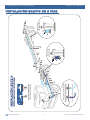
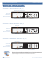
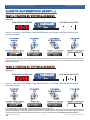
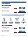
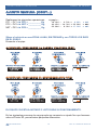
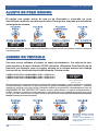
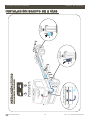
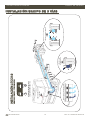
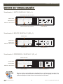
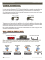
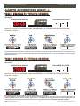
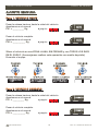
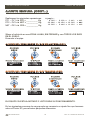
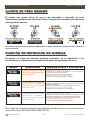
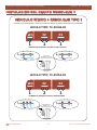
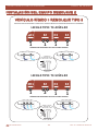
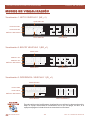
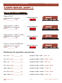
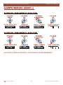
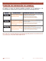
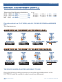
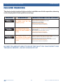
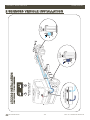
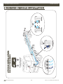
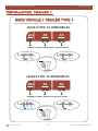
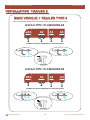
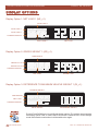
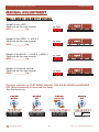
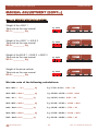
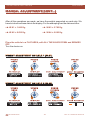
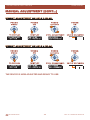
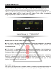
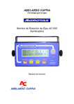
CONTENIDO
3
4
DATOS TÉCNICOS Y KIT DE INSTALACIÓN
VEHÍCULO ARTICULADO
4
5
6
7
9
11
12
Instalación equipo de 2 sensores
Instalación equipo de 3 sensores
Modos de visualización
Ajuste automático
Ajuste manual
Ajuste de peso máximo y cambio de vehículo
Función de detección de averías
13
VEHÍCULO RÍGIDO
13
14
15
16
18
20
Instalación equipo de 2 sensores
Instalación equipo de 3 sensores
Modos de visualización
Ajuste automático
Ajuste manual
Función de detección de averías y ajuste de peso máximo
21
VEHÍCULO TREN DE CARRETERA
21
22
23
24
28
29
Vehículo rígido + remolque tipo 1
Vehículo rígido + remolque tipo 2
Modos de visualización
Ajuste manual
Ajuste de peso máximo y cambio de vehículo
Función de detección de averías
APP ANDROID
30
30
31
Plastecnic Blue V2 (Articulados y rígidos)
Plastecnic Blue V3 (Trenes de carretera)
Instrucciones de seguridad.
Lea con atención las siguientes instrucciones de seguridad. El no seguirlas puede ser peligroso o ilegal.
- Para la instalación del equipo siga las instrucciones que aparecen en este manual.
- Exclusivamente puede instalar o reparar el lector de carga una persona encargada y cualificada.
- Atención, la humedad puede dañar gravemente el aparato. Colóquelo en lugar seco.
- Tenga en cuenta que para una lectura correcta del peso, el vehículo debe estar en una zona llana, con todos
los ejes en el suelo y sin frenar.
- El equipo lee instantáneamente la presión en la suspensión. La lentitud o rapidez en indicar el peso
correcto depende exclusivamente de la velocidad con la que el vehículo alcanza la altura correcta en los
procesos de carga.
- Se recomienda hacer una copia de los datos importantes (Factores de los ejes), una vez ajustado.
- Utilice siempre el equipo con el vehiculo inmovilizado.
PLASTECNIC
2
ED. 01 MAN/0215/ES-IN
DATOS TÉCNICOS
Datos Técnicos de elementos del visor:
Dimensiones: 175x52x40 mm. Adaptable a hueco DIN estándar.
Color: ABS Negro.
Display: Gráfico de 160 x32 retroiluminado con rango extendido de temperatura -20ºC a +70ºC.
Alimentación: 12 - 30 Vcc.
Consumo: 100 mA a 24 Vcc.
Precisión en la medida: Típica 0.5% FS, máxima 0.8% FS.
Resolución: 20 Kg.
Bluetooth.
Datos Técnicos de la caja de sensores:
Dimensiones: 91x166x56 mm.
Color: ABS Negro estanca.
Rango: 0 - 10 Bar.
Grado de protección: IP65.
Opciones:
Salida Puerto Serie RS232. (IMPRESORA, PC, GPS o cualquier otro dispositivo con ese estándar de
comunicaciones).
ELEMENTOS DEL KIT DE INSTALACIÓN
PLASTECNIC
3
ED. 01 MAN/0215/ES-IN
INSTALACIÓN LECC6.0
PLASTECNIC
1
1
4
E1
E2
DETALLE CAJA DE SENSORES 2 VÍAS
COLOCAR PROTEGIDA DE LA HUMEDAD
ALIMENTACIÓN VISOR
24 VOLTIOS
NÚMERO DE SENSORES ALTURA
EN LA SUSPENSIÓN NEUMÁTICA
E2
E1
VEHÍCULO ARTICULADO. TIPO ART-2VÍAS
E1
SEÑAL DE AIRE
CABEZA TRACTORA
E2
SEÑAL DE AIRE
SEMIRREMOLQUE
LECC6.0 VEHÍCULO ARTICULADO
MANUAL DE USUARIO
INSTALACIÓN EQUIPO DE 2 VÍAS
ED. 01 MAN/0215/ES-IN
INSTALACIÓN LECC6.0
PLASTECNIC
1
2
5
E1
E1
E2
DETALLE CAJA DE SENSORES 3 VÍAS
COLOCAR PROTEGIDA DE LA HUMEDAD
ALIMENTACIÓN VISOR
24 VOLTIOS
NÚMERO DE SENSORES ALTURA
EN LA SUSPENSIÓN NEUMÁTICA
E2
E1
VEHÍCULO ARTICULADO. TIPO ART-3VÍAS
E1
SEÑAL DE AIRE CABEZA TRACTORA
E2
SEÑAL DE AIRE
SEMIRREMOLQUE
LECC6.0 VEHÍCULO ARTICULADO
MANUAL DE USUARIO
INSTALACIÓN EQUIPO DE 3 VÍAS
ED. 01 MAN/0215/ES-IN
LECC6.0 VEHÍCULO ARTICULADO
MANUAL DE USUARIO
MODOS DE VISUALIZACIÓN
Visualización 1: NETO VEHÍCULO 1 (NE_v1)
PESO EN EJE1 (Cabeza tractora)
PESO TARA
PESO BRUTO
GRÁFICO DE CARGA
PESO EN EJE2 (Semirremolque)
PESO NETO
Visualización 2: BRUTO VEHÍCULO 1 (BR_v1)
PESO TARA
PESO EJE1
PESO EJE2
GRÁFICO DE CARGA
PESO NETO
PESO BRUTO
Visualización 3: DIFERENCIA VEHÍCULO 1 (DI_v1)
PESO MÁXIMO
PESO TARA
PESO NETO
GRÁFICO DE CARGA
PESO BRUTO
PULSAR
subir/bajar
OK
MENU
Esc
PLASTECNIC
PESO DIFERENCIA
Para el cambio entre las diferentes visualizaciónes se utilizan los botones de subir y
bajar. El equipo memorizará la visualización con la que se apaga, es decir, si el
equipo se apaga en la vista de bruto se encenderá con la misma.
6
ED. 01 MAN/0215/ES-IN
LECC6.0 VEHÍCULO ARTICULADO
MANUAL DE USUARIO
AJUSTE AUTOMÁTICO
Lo que nosotros llamamos E1 Y E2 (ver instalación), se puede corresponder con
uno o varios ejes del vehículo dependiendo de la estructura de la suspensión.
Con el mismo peso neto el vehículo puede llevar mayor o menor carga en los ejes
dependiendo de su distribución.
Neto = 25000
¿E1?
Neto = 25000
¿E2?
¿E1?
¿E2?
Tenemos pues dos puntos de medida en los vehículos articulados y debemos
saber cuánto peso soporta cada uno de ellos. Los procesos y cálculos necesarios
para determinar esos pesos es lo que se llamamos ajuste del equipo.
En el ajuste automático las operaciones matemáticas las realiza el propio visor
siendo así el método más sencillo.
PASO 1. PESAR EL VEHÍCULO VACÍO
Ejemplo:
PESO BRUTO EN BÁSCULA
PESO BRUTO EN LECTOR
VACÍO
Situar el vehículo en una ZONA LLANA, SIN FRENAR y con TODOS LOS EJES
EN EL SUELO. (Aconsejamos realizar esta operación con medio depósito)
Encender el equipo:
PULSAR
MENU
OK
MENU
Esc
Hasta Visualizar
AJUSTAR TARA?
(1/6) V:1/8
PLASTECNIC
PULSAR
OK
OK
MENU
PULSAR
subir/bajar
OK
Esc
DISPLAY
MENU
Esc
Hasta ajustar
-Ok- SOLO VACIO
Tara = 14200 Kg
PULSAR
OK
OK
MENU
Esc
Tara Ajustada
-Ok- SOLO VACIO
Tara = 14740 Kg
7
ED. 01 MAN/0215/ES-IN
LECC6.0 VEHÍCULO ARTICULADO
MANUAL DE USUARIO
AJUSTE AUTOMÁTICO (CONT...)
PASO 2. PESAMOS EL VEHÍCULO CARGADO
Ejemplo:
CARGADO
PESO BRUTO EN BÁSCULA
PESO BRUTO EN LECTOR
Situar el vehículo en una ZONA LLANA, SIN FRENAR y con TODOS LOS EJES EN EL SUELO.
Encender el equipo:
PULSAR
MENU
OK
MENU
Esc
Hasta Visualizar
-AUTO- AJUSTE?
(2/6) V:1/8
PULSAR
OK
OK
MENU
PULSAR
subir/bajar
Esc
OK
DISPLAY
MENU
OK
Esc
Hasta ajustar
Proceso carga n1
P.B. = 38820 Kg
PULSAR
OK
MENU
Esc
Peso Ajustado
Proceso carga n1
P.B. = 40620 Kg
Una vez realizados estos dos pasos, es posible que no se requiera el tercero ya que el equipo puede medir el peso correctamente en los
siguientes procesos de carga. En el caso de que existan diferencias pasaríamos al Paso 3, en el que volveríamos a introducir el peso
bruto total del vehículo.
PASO 3. PESAMOS EL VEHÍCULO CARGADO
Ejemplo:
CARGADO
PESO BRUTO EN BÁSCULA
PESO BRUTO EN LECTOR
Situar el vehículo en una ZONA LLANA, SIN FRENAR y con TODOS LOS EJES EN EL SUELO.
Encender el equipo:
PULSAR
MENU
OK
MENU
Esc
Hasta Visualizar
-AUTO- AJUSTE?
(2/6) V:1/8
PULSAR
subir/bajar
PULSAR
OK
OK
MENU
OK
Esc
MENU
Esc
Hasta ajustar
DISPLAY
Proceso carga n2
P.B. = 41420 Kg
PULSAR
OK
OK
MENU
Esc
Peso Ajustado
Proceso carga n2
P.B. = 40280 Kg
Si en pantalla aparece -Proceso COM- el equipo está programado y listo para su uso.
Si en pantalla aparece -Proceso INC- el equipo no pudo calcular los factores por ser los procesos de carga demasiado parecidos en
cuanto a su distribución o la diferencia de pesos muy pequeña. Le aconsejamos que el siguiente proceso de carga lo haga de manera no
uniforme para que el equipo pueda realizar los cálculos o reiniciar el proceso pulsando la tecla de MENU (PROCESO CARGA N1).
PLASTECNIC
8
ED. 01 MAN/0215/ES-IN
LECC6.0 VEHÍCULO ARTICULADO
MANUAL DE USUARIO
AJUSTE MANUAL
Paso 1. VEHÍCULO VACÍO
Pesar la cabeza tractora, hasta los pies de apoyo.
Apuntamos en el manual
PV1 = _________ Kg
Ejemplo:
VACÍO
Pesar el vehículo completo.
Apuntamos en el manual
PV2 = __________ Kg
VACÍO
Ejemplo:
Situar el vehículo en una ZONA LLANA, SIN FRENAR y con TODOS LOS EJES
EN EL SUELO. (Aconsejamos realizar esta operación con medio depósito)
Encender el equipo:
PULSAR
MENU
OK
MENU
PULSAR
OK
Esc
Hasta Visualizar
AJUSTAR TARA?
(1/6) V:1/8
OK
MENU
PULSAR
subir/bajar
OK
Esc
DISPLAY
MENU
Esc
Hasta ajustar
-Ok- SOLO VACIO
Tara = 14200 Kg
PULSAR
OK
OK
MENU
Esc
Tara Ajustada
-Ok- SOLO VACIO
Tara = 14740 Kg
Paso 2. VEHÍCULO CARGADO
Pesar la cabeza tractora, hasta los pies de apoyo.
Apuntamos en el manual
PC1 = _________ Kg
Ejemplo:
CARGADO
Pesar el vehículo completo.
Apuntamos en el manual
PC2 = __________ Kg
CARGADO
PLASTECNIC
Ejemplo:
9
ED. 01 MAN/0215/ES-IN
LECC6.0 VEHÍCULO ARTICULADO
MANUAL DE USUARIO
AJUSTE MANUAL (CONT...)
Realizamos las siguientes operaciones:
PC1 – PV1 =► PE1 = __________ Kg
PC2 – PV2 =► NET = __________ Kg
NET – PE1 =► PE2 = __________ Kg
Ejemplo:
18.020 – 9.700 = 8.320
40.620 – 14.740 = 25.880
25.880 – 8.320 = 17.560
= PE1
= NET
= PE2
Situar el vehículo en una ZONA LLANA, SIN FRENAR y con TODOS LOS EJES
EN EL SUELO.
Encender el equipo:
AJUSTE DEL PESO SOBRE LA CABEZA TRACTORA (P.E1)
PULSAR
MENU
OK
MENU
Esc
Hasta Visualizar
A. FACTOR E.1?
(5/6) V:1/8
PULSAR
OK
OK
MENU
PULSAR
subir/bajar
Esc
OK
DISPLAY
MENU
PULSAR
OK
OK
Esc
Hasta ajustar
F.E1 = [2200]
P.E1 =+09280 Kg
MENU
Esc
Eje1 Ajustado
F.E1 = [2035]
P.E1 =+08320 Kg
AJUSTE DEL PESO SOBRE EL SEMIRREMOLQUE (P.E2)
PULSAR
MENU
OK
MENU
Esc
Hasta Visualizar
A. FACTOR E.2?
(6/6) V:1/8
PULSAR
OK
OK
MENU
PULSAR
subir/bajar
OK
Esc
DISPLAY
MENU
Esc
Hasta ajustar
F.E2 = [1400]
P.E2 =+19200 Kg
PULSAR
OK
OK
MENU
Esc
Eje2 Ajustado
F.E2 = [1371]
P.E2 =+17560 Kg
EL EQUIPO YA ESTA AJUSTADO Y LISTO PARA SU FUNCIONAMIENTO.
En los siguientes procesos de carga puede ser necesario un ajuste fino que haremos
sobre el Factor E2, para eliminar pequeñas diferencias.
PLASTECNIC
10
ED. 01 MAN/0215/ES-IN
LECC6.0 VEHÍCULO ARTICULADO
MANUAL DE USUARIO
AJUSTE DE PESO MÁXIMO
El equipo nos puede avisar de que se ha alcanzado o superado un peso
determinado mediante una alarma acústica. Para ajustar ese peso procederemos
de la siguiente manera:
PULSAR
PULSAR
PULSAR
PULSAR
OK
subir/bajar
OK
MENU
OK
MENU
Esc
Hasta Visualizar
AJUSTAR PMA?
(4/6) V:1/8
OK
MENU
Esc
OK
DISPLAY
MENU
Esc
OK
Hasta ajustar
AJUSTAR ALARMA
P.M. = +39800 Kg
MENU
Esc
P.M. Ajustado
AJUSTAR ALARMA
P.M. = +41000 Kg
Por ejemplo: ajustado el peso máximo a 41000 kilos, el equipo emitirá unos pitidos cuando se alcance o
supere ese peso.
CAMBIO DE VEHÍCULO
Con este nuevo software el equipo es capaz de almacenar los valores de tara,
peso máximo y factores de hasta OCHO vehículos diferentes. Esta función se ha
pensado, por ejemplo, para un equipo situado en la cabeza tractora que trabaja
con mas de un semirremolque habitualmente. De este modo:
CABEZA TRACTORA + SEMIRREMOLQUE 1 = VEHÍCULO 1
CABEZA TRACTORA + SEMIRREMOLQUE 2 = VEHÍCULO 2
CABEZA TRACTORA + SEMIRREMOLQUE 3 = VEHÍCULO 3
......
AJUSTAR TARA?
(1/6) V:1/8
Número de VEHÍCULO
(Vehículo 1 de 8)
Supongamos que hemos programado el equipo para el semirremolque 1, y que procedemos a cambiar
de semirremolque, entonces, sin que se pierdan los ajustes realizados para el vehículo 1, debemos
cambiar de vehiculo en el visor (V:2/8) y después realizar la programación correspondiente. Una vez
programados los dos vehículos, sus valores quedan memorizados en lugares independientes y
cuando volvamos a cambiar al semirremolque 1 solo tendremos que cambiar de vehículo en el visor
(V:1/8) y de este modo el visor recogerá los datos almacenados anteriormente. Este proceso se puede
realizar hasta para 8 semirremolques.
PULSAR
MENU
OK
MENU
Esc
Hasta Visualizar
NUM. VEHICULO?
(3/6) V:1/8
PLASTECNIC
PULSAR
OK
OK
MENU
PULSAR
subir/bajar
OK
Esc
DISPLAY
MENU
Esc
Hasta ajustar
CAMBIO VEHICULO
NUMERO = V:1/8
CAMBIO VEHICULO
NUMERO = V:2/8
11
PULSAR
OK
OK
MENU
Esc
Cambio Realizado
En este caso:
La TARA, el PESO MÁXIMO y los
factores de los EJES serán ahora
del VEHÍCULO 2.
ED. 01 MAN/0215/ES-IN
LECC6.0 VEHÍCULO ARTICULADO
MANUAL DE USUARIO
FUNCIÓN DE DETECCIÓN DE AVERÍAS
El equipo es capaz de detectar posibles anomalías en la instalación o de
funcionamiento, apareciendo en pantalla los siguientes mensajes de error:
ERROR
DESCRIPCIÓN
POSIBLES CAUSAS Y SOLUCIONES
- ERROR EJEX *1* VER MANUAL
El visor no detecta el sensor
o sensores del eje de medida
número X (1 o 2).
El cable esta desconectado o averiado.
Comprobar que el cable esta conectado en sus dos extremos.
Comprobar que el cable no este dañado.
Sustituir el cable en el caso de que sea necesario.
El sensor o sensores del eje están averiados.
Contactar con el servicio técnico para su reparación .
- ERROR EJEX *2* VER MANUAL
El visor detecta una presión
muy baja en el sensor o
sensores del eje de medida
número X (1 o 2).
La presión que llega al sensor es muy baja.
Comprobar la instalación. El tecalán que lleva el aire al sensor puede
estar pinzado u obstruido .
La presión que detecta el sensor es próxima a 0 Bares. Verificar.
El sensor o sensores del eje están averiados.
Contactar con el servicio técnico para su reparación .
- ERROR EJEX *3* VER MANUAL
El visor detecta una presión
muy alta en el sensor o
sensores del eje de medida
número X (1 o 2).
La presión que llega al sensor es muy alta.
Comprobar la instalación. Verificar que el aire que le llegue al sensor
sea realmente el de la balona y no el del calderin de la suspensión.
La presión que detecta el sensor es próxima a 10 Bares. Verificar.
El sensor o sensores del eje están averiados.
Contactar con el servicio técnico para su reparación .
En el caso de no poder solucionar el problema puede ponerse en contacto con el
servicio técnico. Tel: 663 910 260 / 646 570 327
PLASTECNIC
12
ED. 01 MAN/0215/ES-IN
INSTALACIÓN LECC6.0
PLASTECNIC
1
1
13
E1
E2
DETALLE CAJA DE SENSORES 2 VÍAS
COLOCAR PROTEGIDA DE LA HUMEDAD
ALIMENTACIÓN VISOR
24 VOLTIOS
NÚMERO DE SENSORES ALTURA
EN LA SUSPENSIÓN NEUMÁTICA
E2
E1
VEHÍCULO RÍGIDO. TIPO RIG-2VÍAS
E1
SEÑAL DE AIRE
EJE DELANTERO
E2
SEÑAL DE AIRE
EJE TRASERO
LECC6.0 VEHÍCULO RÍGIDO
MANUAL DE USUARIO
INSTALACIÓN EQUIPO DE 2 VÍAS
ED. 01 MAN/0215/ES-IN
INSTALACIÓN LECC6.0
PLASTECNIC
2
1
14
E1
E2
E2
DETALLE CAJA DE SENSORES 3 VÍAS
COLOCAR PROTEGIDA DE LA HUMEDAD
ALIMENTACIÓN VISOR
24 VOLTIOS
NÚMERO DE SENSORES ALTURA
EN LA SUSPENSIÓN NEUMÁTICA
E2
E1
VEHÍCULO RÍGIDO. TIPO RIG-3VÍAS
E1
SEÑAL DE AIRE
EJE DELANTERO
E2
SEÑAL DE AIRE EJE TRASERO
LECC6.0 VEHÍCULO RÍGIDO
MANUAL DE USUARIO
INSTALACIÓN EQUIPO DE 3 VÍAS
ED. 01 MAN/0215/ES-IN
LECC6.0 VEHÍCULO RÍGIDO
MANUAL DE USUARIO
MODOS DE VISUALIZACIÓN
Visualización 1: NETO VEHÍCULO 1 (NE_v1)
PESO EN EJE1 (Eje delantero)
PESO TARA
PESO BRUTO
GRÁFICO DE CARGA
PESO EN EJE2 (Eje trasero)
PESO NETO
Visualización 2: BRUTO VEHÍCULO 1 (BR_v1)
PESO TARA
PESO EJE1
PESO EJE2
GRÁFICO DE CARGA
PESO NETO
PESO BRUTO
Visualización 3: DIFERENCIA VEHÍCULO 1 (DI_v1)
PESO MÁXIMO
PESO TARA
PESO NETO
GRÁFICO DE CARGA
PESO BRUTO
PULSAR
subir/bajar
OK
MENU
Esc
PLASTECNIC
PESO DIFERENCIA
Para el cambio entre las diferentes visualizaciónes se utilizan los botones de subir y
bajar. El equipo memorizará la visualización con la que se apaga, es decir, si el
equipo se apaga en la vista de bruto se encenderá con la misma.
15
ED. 01 MAN/0215/ES-IN
LECC6.0 VEHÍCULO RÍGIDO
MANUAL DE USUARIO
AJUSTE AUTOMÁTICO
Lo que nosotros llamamos E1 Y E2 (ver instalación), se puede corresponder con
uno o varios ejes del vehículo dependiendo de la estructura de la suspensión.
Con el mismo peso neto el vehículo puede llevar mayor o menor carga en los ejes
dependiendo de su distribución.
Neto = 15000
¿E1?
Neto = 15000
¿E2?
¿E1?
¿E2?
Tenemos pues dos puntos de medida en los vehículos rígidos y debemos saber
cuánto peso soporta cada uno de ellos. Los procesos y cálculos necesarios para
determinar esos pesos es lo que se llamamos ajuste del equipo.
En el ajuste automático las operaciones matemáticas las realiza el propio visor
siendo así el método más sencillo.
PASO 1. PESAR EL VEHÍCULO VACÍO
Ejemplo:
PESO BRUTO EN BÁSCULA
PESO BRUTO EN LECTOR
VACÍO
Situar el vehículo en una ZONA LLANA, SIN FRENAR y con TODOS LOS EJES
EN EL SUELO. (Aconsejamos realizar esta operación con medio depósito)
Encender el equipo:
PULSAR
MENU
OK
MENU
Esc
Hasta Visualizar
AJUSTAR TARA?
(1/6) V:1/8
PLASTECNIC
PULSAR
OK
OK
MENU
PULSAR
subir/bajar
Esc
OK
DISPLAY
MENU
Esc
Hasta ajustar
-Ok- SOLO VACIO
Tara = 14200 Kg
PULSAR
OK
OK
MENU
Esc
Tara Ajustada
-Ok- SOLO VACIO
Tara = 12620 Kg
16
ED. 01 MAN/0215/ES-IN
LECC6.0 VEHÍCULO RÍGIDO
MANUAL DE USUARIO
AJUSTE AUTOMÁTICO (CONT...)
PASO 2. PESAMOS EL VEHÍCULO CARGADO
Ejemplo:
PESO BRUTO EN BÁSCULA
PESO BRUTO EN LECTOR
CARGADO
Situar el vehículo en una ZONA LLANA, SIN FRENAR y con TODOS LOS EJES EN EL SUELO.
Encender el equipo:
PULSAR
MENU
OK
MENU
Esc
Hasta Visualizar
-AUTO- AJUSTE?
(2/6) V:1/8
PULSAR
OK
OK
MENU
PULSAR
subir/bajar
Esc
OK
DISPLAY
MENU
Esc
OK
Hasta ajustar
Proceso carga n1
P.B. = 28720 Kg
PULSAR
OK
MENU
Esc
Peso Ajustado
Proceso carga n1
P.B. = 25460 Kg
Una vez realizados estos dos pasos, es posible que no se requiera el tercero ya que el equipo puede medir el peso correctamente en los
siguientes procesos de carga. En el caso de que existan diferencias pasaríamos al Paso 3, en el que volveríamos a introducir el peso
bruto total del vehículo.
PASO 3. PESAMOS EL VEHÍCULO CARGADO
Ejemplo:
PESO BRUTO EN BÁSCULA
PESO BRUTO EN LECTOR
CARGADO
Situar el vehículo en una ZONA LLANA, SIN FRENAR y con TODOS LOS EJES EN EL SUELO.
Encender el equipo:
PULSAR
MENU
OK
MENU
Esc
Hasta Visualizar
-AUTO- AJUSTE?
(2/6) V:1/8
PULSAR
OK
OK
MENU
PULSAR
subir/bajar
OK
Esc
DISPLAY
MENU
Esc
Hasta ajustar
Proceso carga n2
P.B. = 24660 Kg
PULSAR
OK
OK
MENU
Esc
Peso Ajustado
Proceso carga n2
P.B. = 25800 Kg
Si en pantalla aparece -Proceso COM- el equipo está programado y listo para su uso.
Si en pantalla aparece -Proceso INC- el equipo no pudo calcular los factores por ser los procesos de carga demasiado parecidos en
cuanto a su distribución o la diferencia de pesos muy pequeña. Le aconsejamos que el siguiente proceso de carga lo haga de manera no
uniforme para que el equipo pueda realizar los cálculoso reiniciar el proceso pulsando la tecla de MENU (PROCESO CARGA N1).
PLASTECNIC
17
ED. 01 MAN/0215/ES-IN
LECC6.0 VEHÍCULO RÍGIDO
MANUAL DE USUARIO
AJUSTE MANUAL
Paso 1. VEHÍCULO VACÍO
Pesar la cabeza tractora, hasta la mitad del vehículo.
Apuntamos en el manual
PV1 = _________ Kg
Ejemplo:
VACÍO
Pesar el vehículo completo.
Apuntamos en el manual
PV2 = __________ Kg
VACÍO
Ejemplo:
Situar el vehículo en una ZONA LLANA, SIN FRENAR y con TODOS LOS EJES
EN EL SUELO. (Aconsejamos realizar esta operación con medio depósito)
Encender el equipo:
PULSAR
MENU
OK
MENU
PULSAR
OK
Esc
Hasta Visualizar
AJUSTAR TARA?
(1/5)
OK
MENU
PULSAR
subir/bajar
Esc
OK
DISPLAY
MENU
Esc
Hasta ajustar
-Ok- SOLO VACIO
Tara = 14200 Kg
PULSAR
OK
OK
MENU
Esc
Tara Ajustado
-Ok- SOLO VACIO
Tara = 12620 Kg
Paso 2. VEHÍCULO CARGADO
Pesar la cabeza tractora, hasta la mitad del vehículo.
Apuntamos en el manual
PC1 = _________ Kg
Ejemplo:
CARGADO
Pesar el vehículo completo.
Apuntamos en el manual
PC2 = __________ Kg
CARGADO
PLASTECNIC
Ejemplo:
18
ED. 01 MAN/0215/ES-IN
LECC6.0 VEHÍCULO RÍGIDO
MANUAL DE USUARIO
AJUSTE MANUAL (CONT...)
Realizamos las siguientes operaciones:
PC1 – PV1 =► PE1 = __________ Kg
PC2 – PV2 =► NET = __________ Kg
NET – PE1 =► PE2 = __________ Kg
Ejemplo:
8.560 – 6.120 = 2.440
25.880 – 12.620 = 13.260
13.260 – 2.440 = 10.820
= PE1
= NET
= PE2
Situar el vehículo en una ZONA LLANA, SIN FRENAR y con TODOS LOS EJES
EN EL SUELO.
Encender el equipo:
AJUSTE DEL PESO SOBRE EL EJE DELANTERO (P.E1)
PULSAR
MENU
OK
MENU
Esc
Hasta Visualizar
A. FACTOR E.1?
(4/5)
PULSAR
OK
OK
MENU
PULSAR
subir/bajar
Esc
OK
DISPLAY
MENU
Esc
Hasta ajustar
F.E1 = [0300]
P.E1 =+01280 Kg
PULSAR
OK
OK
MENU
Esc
Eje1 Ajustado
F.E1 = [0417]
P.E1 =+02440 Kg
AJUSTE DEL PESO SOBRE EL EJE TRASERO (P.E2)
PULSAR
MENU
OK
MENU
Esc
Hasta Visualizar
A. FACTOR E.2?
(5/5)
PULSAR
OK
OK
MENU
PULSAR
subir/bajar
Esc
OK
DISPLAY
MENU
Esc
Hasta ajustar
F.E2 = [0300]
P.E2 =+03240 Kg
PULSAR
OK
OK
MENU
Esc
Eje2 Ajustado
F.E2 = [0728]
P.E2 =+10820 Kg
EL EQUIPO YA ESTA AJUSTADO Y LISTO PARA SU FUNCIONAMIENTO.
En los siguientes procesos de carga puede ser necesario un ajuste fino que haremos
sobre el Factor E2, para eliminar pequeñas diferencias.
PLASTECNIC
19
ED. 01 MAN/0215/ES-IN
LECC6.0 VEHÍCULO RÍGIDO
MANUAL DE USUARIO
AJUSTE DE PESO MÁXIMO
El equipo nos puede avisar de que se ha alcanzado o superado un peso
determinado mediante una alarma acústica. Para ajustar ese peso procederemos
de la siguiente manera:
PULSAR
MENU
OK
MENU
PULSAR
OK
Esc
OK
Hasta Visualizar
AJUSTAR PMA?
(3/5)
MENU
PULSAR
subir/bajar
Esc
OK
DISPLAY
MENU
PULSAR
OK
Esc
OK
Hasta ajustar
AJUSTAR ALARMA
P.M. = +24800 Kg
MENU
Esc
P.M. Ajustado
AJUSTAR ALARMA
P.M. = +26000 Kg
Por ejemplo: ajustado el peso máximo a 26000 kilos, el equipo emitirá unos pitidos cuando se alcance o
supere ese peso.
FUNCIÓN DE DETECCIÓN DE AVERÍAS
El equipo es capaz de detectar posibles anomalías en la instalación o de
funcionamiento, apareciendo en pantalla los siguientes mensajes de error:
ERROR
DESCRIPCIÓN
POSIBLES CAUSAS Y SOLUCIONES
- ERROR EJEX *1* VER MANUAL
El visor no detecta el sensor
o sensores del eje de medida
número X (1 o 2).
El cable esta desconectado o averiado.
Comprobar que el cable esta conectado en sus dos extremos.
Comprobar que el cable no este dañado.
Sustituir el cable en el caso de que sea necesario.
El sensor o sensores del eje están averiados.
Contactar con el servicio técnico para su reparación .
- ERROR EJEX *2* VER MANUAL
El visor detecta una presión
muy baja en el sensor o
sensores del eje de medida
número X (1 o 2).
La presión que llega al sensor es muy baja.
Comprobar la instalación. El tecalán que lleva el aire al sensor puede
estar pinzado u obstruido .
La presión que detecta el sensor es próxima a 0 Bares. Verificar.
El sensor o sensores del eje están averiados.
Contactar con el servicio técnico para su reparación .
- ERROR EJEX *3* VER MANUAL
El visor detecta una presión
muy alta en el sensor o
sensores del eje de medida
número X (1 o 2).
La presión que llega al sensor es muy alta.
Comprobar la instalación. Verificar que el aire que le llegue al sensor
sea realmente el de la balona y no el del calderin de la suspensión.
La presión que detecta el sensor es próxima a 10 Bares. Verificar.
El sensor o sensores del eje están averiados.
Contactar con el servicio técnico para su reparación .
En el caso de no poder solucionar el problema puede ponerse en contacto con el
servicio técnico. Tel: 663 910 260 / 646 570 327
PLASTECNIC
20
ED. 01 MAN/0215/ES-IN
LECC6.0 VEHÍCULO TREN DE CARRETERA
MANUAL DE USUARIO
INSTALACIÓN DEL EQUIPO REMOLQUE 1
VEHICULO RÍGIDO + REMOLQUE TIPO 1
COLOCAR CAJAS DE SENSORES Y VISOR EN EL VEHICULO RÍGIDO EN ZONAS PROTEGIDAS DE LA HUMEDAD
LECC6.0 TIPO: TC-3VÍAS-R1
E1
E2
E3
1
1
1
NÚMERO DE SENSORES ALTURA O NIVELADORAS
DETALLE CAJA DE SENSORES 1
DETALLE CAJA DE SENSORES 2
E2
E1
E3
E4
DETALLE
Conexión aire
LECC6.0 TIPO: TC-4VÍAS-R1
E1
E2
E3
1
2
1
NÚMERO DE SENSOR ALTURA O NIVELADORAS
DETALLE CAJA DE SENSORES 1
E1
E2
DETALLE CAJA DE SENSORES 2
E3
E2
E4
DETALLE
Conexión aire
PLASTECNIC
21
ED. 01 MAN/0215/ES-IN
LECC6.0 VEHÍCULO TREN DE CARRETERA
MANUAL DE USUARIO
INSTALACIÓN DEL EQUIPO REMOLQUE 2
VEHÍCULO RÍGIDO + REMOLQUE TIPO 2
COLOCAR CAJAS DE SENSORES Y VISOR EN EL VEHICULO RÍGIDO EN ZONAS PROTEGIDAS DE LA HUMEDAD
LECC6.0 TIPO: TC-4VÍAS-R2
E1
E2
E3
E4
1
1
1
1
NÚMERO DE SENSORES ALTURA O NIVELADORAS
DETALLE CAJA DE SENSORES 1
DETALLE CAJA DE SENSORES 2
E2
E1
E4
E3
DETALLE
Conexión aire
LECC6.0 TIPO: TC-5VÍAS-R2
E1
E2
E3
E4
1
2
1
1
NÚMERO DE SENSORES ALTURA O NIVELADORAS
DETALLE CAJA DE SENSORES 1
E1
E2
DETALLE CAJA DE SENSORES 2
E3
E2
E4
DETALLE
Conexión aire
PLASTECNIC
22
ED. 01 MAN/0215/ES-IN
LECC6.0 VEHÍCULO TREN DE CARRETERA
MANUAL DE USUARIO
MODOS DE VISUALIZACIÓN
Visualización 1: NETO VEHÍCULO 1 (NE_v1)
PESO EN EJE3
PESO EN EJE1
PESO EN EJE2
GRÁFICO DE CARGA
PESO EN EJE4
PESO NETO
Visualización 2: BRUTO VEHÍCULO 1 (BR_v1)
PESO TARA
PESO E1+E2
PESO E3+E4
GRÁFICO DE CARGA
PESO NETO
PESO BRUTO
Visualización 3: DIFERENCIA VEHÍCULO 1 (DI_v1)
PESO MÁXIMO
PESO TARA
PESO NETO
GRÁFICO DE CARGA
PESO BRUTO
PULSAR
subir/bajar
OK
MENU
Esc
PLASTECNIC
PESO DIFERENCIA
Para el cambio entre las diferentes visualizaciónes se utilizan los botones de subir y
bajar. El equipo memorizará la visualización con la que se apaga, es decir, si el
equipo se apaga en la vista de bruto se encenderá con la misma.
23
ED. 01 MAN/0215/ES-IN
LECC6.0 VEHÍCULO TREN DE CARRETERA
MANUAL DE USUARIO
AJUSTE MANUAL
Paso 1. VEHÍCULO VACÍO
Pesar el EJE 1
Apuntamos en el manual
Pv1 = _________ Kg
EJEMPLO EN BÁSCULA
VACÍO
Pesar el EJE 1 + EJE 2.
Apuntamos en el manual
Pv2 = _________ Kg
EJEMPLO EN BÁSCULA
VACÍO
Pesar el EJE 1 + EJE2 + EJE3.
Apuntamos en el manual
Pv3 = _________ Kg
EJEMPLO EN BÁSCULA
VACÍO
Pesar el vehículo COMPLETO.
Apuntamos en el manual
Pv4 = _________ Kg
EJEMPLO EN BÁSCULA
VACÍO
Situar el vehículo en una ZONA LLANA, SIN FRENAR y con TODOS LOS EJES
EN EL SUELO. (Aconsejamos realizar esta operación con medio depósito)
Encender el equipo:
PULSAR
MENU
OK
MENU
Esc
Hasta Visualizar
AJUSTAR TARA?
(1/7) V:1/8
PLASTECNIC
PULSAR
OK
OK
MENU
PULSAR
subir/bajar
Esc
OK
DISPLAY
MENU
Esc
Hasta ajustar
-Ok- SOLO VACIO
Tara = 14200 Kg
PULSAR
OK
OK
MENU
Esc
Tara Ajustada
-Ok- SOLO VACIO
Tara = 17820 Kg
24
ED. 01 MAN/0215/ES-IN
LECC6.0 VEHÍCULO TREN DE CARRETERA
MANUAL DE USUARIO
AJUSTE MANUAL (CONT...)
Paso 2. VEHÍCULO CARGADO
Pesar el EJE 1
Apuntamos en el manual
Pc1 = _________ Kg
EJEMPLO EN BÁSCULA
CARGADO
Pesar el EJE 1 + EJE 2.
Apuntamos en el manual
Pc2 = _________ Kg
EJEMPLO EN BÁSCULA
CARGADO
Pesar el EJE 1 + EJE 2 + EJE 3.
Apuntamos en el manual
Pc3 = _________ Kg
EJEMPLO EN BÁSCULA
CARGADO
Pesar el vehículo COMPLETO.
Apuntamos en el manual
Pc4 = _________ Kg
EJEMPLO EN BÁSCULA
CARGADO
Realizamos las siguientes operaciones:
Pc1 – Pv1 =>
E1 = __________ Kg
Ejemplo: 7.760 – 6.120 = 1.640 = E1
Pc2 – Pv2 => Net1 = __________ Kg
Ejemplo: 22.880 – 12.620 = 10.260 = Net1
Net1 – E1 =>
Ejemplo: 10.260 – 1.640 = 8.620 = E2
E2 = __________ Kg
Pc3 – Pv3 => Net2 = __________ Kg
Ejemplo: 31.260 – 15.220 = 16.040 = Net2
Net2 – Net1 => E3 = __________ Kg
Ejemplo: 16.040 – 10.260 = 5.780 = E3
Pc4 – Pv4 => Net3 = __________ Kg
Ejemplo: 17.820 – 39.920 = 22.100 = Net3
Net3 – Net2 => E4 = __________ Kg
Ejemplo: 22.100 – 16.040 = 6.060 = E4
PLASTECNIC
25
ED. 01 MAN/0215/ES-IN
LECC6.0 VEHÍCULO TREN DE CARRETERA
MANUAL DE USUARIO
AJUSTE MANUAL (CONT...)
Después de realizar las operaciones ya tenemos los pesos que soporta cada eje ,
datos que debemos de introducirle al equipo: En el caso del ejemplo serian:
=► P.E1 = 1.640 Kg
=► P.E3 = 5.780 Kg
=► P.E2 = 8.620 Kg
=► P.E4 = 6.060 Kg
Situar el vehículo en una ZONA LLANA, SIN FRENAR y con TODOS LOS EJES
EN EL SUELO.
Encender el equipo:
AJUSTE DEL PESO SOBRE EL EJE 1 (P.E1)
PULSAR
MENU
OK
MENU
Esc
Hasta Visualizar
A. FACTOR E.1?
(4/7) V:1/8
PULSAR
OK
OK
MENU
PULSAR
subir/bajar
Esc
OK
DISPLAY
MENU
Esc
Hasta ajustar
F.E1 = [0101]
P.E1 =+00680 Kg
PULSAR
OK
OK
MENU
Esc
Eje1 Ajustado
F.E1 = [0325]
P.E1 =+01640 Kg
AJUSTE DEL PESO SOBRE EL EJE 2 (P.E2)
PULSAR
MENU
OK
MENU
Esc
Hasta Visualizar
A. FACTOR E.2?
(5/7) V:1/8
PLASTECNIC
PULSAR
OK
OK
MENU
PULSAR
subir/bajar
Esc
OK
DISPLAY
MENU
Esc
Hasta ajustar
F.E2 = [0102]
P.E2 =+00720 Kg
PULSAR
OK
OK
MENU
Esc
Eje2 Ajustado
F.E2 = [0771]
P.E2 =+08620 Kg
26
ED. 01 MAN/0215/ES-IN
LECC6.0 VEHÍCULO TREN DE CARRETERA
MANUAL DE USUARIO
AJUSTE MANUAL (CONT...)
AJUSTE DEL PESO SOBRE EL EJE 3 (P.E3)
PULSAR
MENU
OK
MENU
Esc
Hasta Visualizar
A. FACTOR E.3?
(6/7) V:1/8
PULSAR
OK
OK
MENU
PULSAR
subir/bajar
Esc
OK
DISPLAY
MENU
Esc
Hasta ajustar
F.E3 = [0103]
P.E3 =+00460 Kg
PULSAR
OK
OK
MENU
Esc
Eje3 Ajustado
F.E3 = [0810]
P.E3 =+05780 Kg
AJUSTE DEL PESO SOBRE EL EJE 4 (P.E4)
PULSAR
MENU
OK
MENU
Esc
Hasta Visualizar
A. FACTOR E.4?
(7/7) V:1/8
PULSAR
OK
OK
MENU
PULSAR
subir/bajar
Esc
OK
DISPLAY
MENU
Esc
Hasta ajustar
F.E4 = [0103]
P.E4 =+00540 Kg
PULSAR
OK
OK
MENU
Esc
Eje4 Ajustado
F.E4 = [0628]
P.E4 =+06060 Kg
EL EQUIPO YA ESTA AJUSTADO Y LISTO PARA SU FUNCIONAMIENTO.
PLASTECNIC
27
ED. 01 MAN/0215/ES-IN
LECC6.0 VEHÍCULO TREN DE CARRETERA
MANUAL DE USUARIO
AJUSTE DE PESO MÁXIMO
El equipo nos puede avisar de que se ha alcanzado o superado un peso
determinado mediante una alarma acústica. Para ajustar ese peso procederemos
de la siguiente manera:
PULSAR
PULSAR
PULSAR
PULSAR
OK
MENU
subir/bajar
OK
OK
MENU
Esc
Hasta Visualizar
AJUSTAR PMA?
(2/7) V:1/8
OK
MENU
Esc
OK
DISPLAY
MENU
Esc
OK
Hasta ajustar
AJUSTAR ALARMA
P.M. = +39800 Kg
MENU
Esc
P.M. Ajustado
AJUSTAR ALARMA
P.M. = +40000 Kg
Por ejemplo: ajustado el peso máximo a 40000 kilos, el equipo emitirá unos pitidos cuando se alcance o
supere ese peso.
CAMBIO DE VEHÍCULO
Con este nuevo software el equipo es capaz de almacenar los valores de tara,
peso máximo y factores de hasta OCHO vehículos diferentes. Esta función se ha
pensado, por ejemplo, para un equipo situado en el vehículo rígido que trabaja con
mas de un remolque habitualmente. De este modo:
VEHÍCULO RÍGIDO + REMOLQUE 1 = VEHÍCULO 1
VEHÍCULO RÍGIDO + REMOLQUE 2 = VEHÍCULO 2
VEHÍCULO RÍGIDO + REMOLQUE 3 = VEHÍCULO 3
......
AJUSTAR TARA?
(1/6) V:1/8
Número de VEHÍCULO
(Vehículo 1 de 8)
Supongamos que hemos programado el equipo para el remolque 1, y que procedemos a cambiar de
remolque, entonces, sin que se pierdan los ajustes realizados para el vehículo 1, debemos cambiar de
vehiculo en el visor (V:2/8) y después realizar la programación correspondiente. Una vez programados
los dos vehículos, sus valores quedan memorizados en lugares independientes y cuando volvamos a
cambiar al remolque 1 solo tendremos que cambiar de vehículo en el visor (V:1/8) y de este modo el
visor recogerá los datos almacenados anteriormente. Este proceso se puede realizar hasta para 8
remolques.
PULSAR
MENU
OK
MENU
Esc
Hasta Visualizar
NUM. VEHICULO?
(3/7) V:1/8
PLASTECNIC
PULSAR
OK
OK
MENU
PULSAR
subir/bajar
Esc
OK
DISPLAY
MENU
Esc
Hasta ajustar
CAMBIO VEHICULO
NUMERO = V:1/8
CAMBIO VEHICULO
NUMERO = V:2/8
28
PULSAR
OK
OK
MENU
Esc
Cambio Realizado
En este caso:
La TARA, el PESO MÁXIMO y los
factores de los EJES serán ahora
del VEHÍCULO 2.
ED. 01 MAN/0215/ES-IN
LECC6.0 VEHÍCULO TREN DE CARRETERA
MANUAL DE USUARIO
FUNCIÓN DE DETECCIÓN DE AVERÍAS
El equipo es capaz de detectar posibles anomalías en la instalación o de
funcionamiento, apareciendo en pantalla los siguientes mensajes de error:
ERROR
DESCRIPCIÓN
POSIBLES CAUSAS Y SOLUCIONES
- ERROR EJEX *1* VER MANUAL
El visor no detecta el sensor
o sensores del eje de medida
número X (1,2,3 o 4).
El cable esta desconectado o averiado.
Comprobar que el cable esta conectado en sus dos extremos.
Comprobar que el cable no este dañado.
Sustituir el cable en el caso de que sea necesario.
El sensor o sensores del eje están averiados.
Contactar con el servicio técnico para su reparación .
- ERROR EJEX *2* VER MANUAL
El visor detecta una presión
muy baja en el sensor o
sensores del eje de medida
número X (1 o 2). Sólo en el
vehículo rígido.
La presión que llega al sensor es muy baja.
Comprobar la instalación. El tecalán que lleva el aire al sensor puede
estar pinzado u obstruido .
La presión que detecta el sensor es próxima a 0 Bares. Verificar.
El sensor o sensores del eje están averiados.
Contactar con el servicio técnico para su reparación .
- ERROR EJEX *3* VER MANUAL
El visor detecta una presión
muy alta en el sensor o
sensores del eje de medida
número X (1,2,3 o 4).
La presión que llega al sensor es muy alta.
Comprobar la instalación. Verificar que el aire que le llegue al sensor
sea realmente el de la balona y no el del calderin de la suspensión.
La presión que detecta el sensor es próxima a 10 Bares. Verificar.
El sensor o sensores del eje están averiados.
Contactar con el servicio técnico para su reparación .
En el caso de no poder solucionar el problema puede ponerse en contacto con el
servicio técnico. Tel: 663 910 260 / 646 570 327
PLASTECNIC
29
ED. 01 MAN/0215/ES-IN
APP ANDROID PLASTECNIC BLUE V2
Nuestra aplicación Android BLUE V2 para VEHÍCULOS ARTICULADOS Y RÍGIDOS
se puede bajar directamente de la tienda de Google, Google play:
Primero realizamos el emparejamiento con el dispositivo PLASTECNIC, tan solo
una vez.
APLICACIONES => AJUSTES => CONEXIONES INALÁMBRICAS => BLUETOOTH
(ACTIVAR) => BUSCAR DISPOSITIVOS. Una vez encontrado, introducir el PIN
1234.
Ahora ya está todo configurado para poder utilizar la aplicación y apretando el
botón de conectar aparecerá el dispositivo PLASTECNIC preparado para su
enlace.
En nuestra pagina web: www.mvplastecnic.com podrá encontra mas información.
PLASTECNIC
30
ED. 01 MAN/0215/ES-IN
APP ANDROID PLASTECNIC BLUE V3
Nuestra aplicación Android BLUE V3 para TRENES DE CARRETERA se puede
bajar directamente de la tienda de Google, Google play:
Primero realizamos el emparejamiento con el dispositivo PLASTECNIC, tan solo
una vez.
APLICACIONES => AJUSTES => CONEXIONES INALÁMBRICAS => BLUETOOTH
(ACTIVAR) => BUSCAR DISPOSITIVOS. Una vez encontrado, introducir el PIN
1234.
Ahora ya está todo configurado para poder utilizar la aplicación y apretando el
botón de conectar aparecerá el dispositivo PLASTECNIC preparado para su
enlace.
En nuestra pagina web: www.mvplastecnic.com podrá encontra mas información.
PLASTECNIC
31
ED. 01 MAN/0215/ES-IN
CONTENT
TECHNICAL DATA AND INSTALLATION KIT
ARTICULATED VEHICLE
Two-sensors installation
Three-sensors installation
Display options
Automatic adjustment
Manual adjustment
Setting gross vehicle weight rating and vehicle exchange
Failure warning
34
35
35
36
37
38
40
42
43
44
RIGID VEHICLE
Two-sensors installation
Three-sensors installation
Display options
Automatic adjustment
Manual adjustment
Setting gross vehicle weight rating and failure warning
44
45
46
47
49
51
52
ROAD TRAIN VEHICLE
Installation trailer 1
Installation trailer 2
Display options
Manual adjustment
Setting gross vehicle weight rating and vehicle exchange
Failure warning
52
53
54
55
59
60
61
ANDROID APP
Plastecnic Blue V2 (Articulated and Rigid)
Plastecnic Blue V3 (Road train vehicles)
61
62
SAFETY INSTRUCTIONS.
Please, read carefully following safety instructions. Not following them might be dangerous or illegal.
- For a correct installation, please follow the instructions in this manual.
- The electronic Load Control Reader must be installed by qualified personnel.
- WARNING! Humidity may damage the device. Keep it away from humidity.
- To ensure a correct weight value is calibrated, place the vehicle on a flat area, with all the axles down and
the brakes off.
- The device instantly records the suspension pressure in real time. The amount of time the weight takes to
be displayed depends exclusively on the speed of the vehicle reaching the correct height while loading.
- Once the device is adjusted, it is advised to keep a copy of F.A1 y F.A2 data.
- Always use the device with the vehicle immobilized.
PLASTECNIC
33
ED. 01 MAN/0215/ES-IN
TECHNICAL DATA
DISPLAY TECHNICAL DATA:
Dimensions: 175x52x40mm. Adaptable to standard DIN.
Colour: ABS Black.
Display: 160x32 liquid crystal, back-lighted. Rank of temperature from 20ºC to +70ºC.
Supply: 12-30 Vcc.
Consumption: 100 mA at 24 Vcc.
Accuracy of measurement: Standard ± 0.5% FS, maximum ± 0.8% FS.
Steps: 20 Kg.
Bluetooth.
SENSOR BOX TECHNICAL DATA:
Dimensions: 91x166x56mm.
Colour: ABS Black.
Rank: 0-10 Bar.
Degree of protection: IP65.
OPTIONS:
RS232 Serial Output. (Printer, PC,GPS or any other device with the same connection).
INSTALLATION KIT
PLASTECNIC
34
ED. 01 MAN/0215/ES-IN
LECC6.0 INSTALLATION
PLASTECNIC
1
1
35
A1
A2
2 SENSORS BOX
KEEP AWAY FROM WET AREAS
DISPLAY POWER SUPPLY
24 VOLTS
NUMBER OF HEIGHT SENSORS
OF THE AIR SUSPENSION
A2
A1
ARTICULATED VEHICLE TYPE ART-2SENSORS
A1
TRUCK
AIR SIGNAL
A2
SEMITRAILER
AIR SIGNAL
LECC6.0 ARTICULATED VEHICLE
USER MANUAL
2 SENSORS VEHICLE INSTALLATION
ED. 01 MAN/0215/ES-IN
LECC6.0 INSTALLATION
PLASTECNIC
1
2
36
A1
A1
A2
3 SENSORS BOX
KEEP AWAY FROM WET AREAS
DISPLAY POWER SUPPLY
24 VOLTS
NUMBER OF HEIGHT SENSORS
OF THE AIR SUSPENSION
A2
A1
ARTICULATED VEHICLE TYPE ART-3SENSORS
A1
TRUCK AIR SIGNAL
A2
SEMITRAILER
AIR SIGNAL
LECC6.0 ARTICULATED VEHICLE
USER MANUAL
3 SENSORS VEHICLE INSTALLATION
ED. 01 MAN/0215/ES-IN
LECC6.0 ARTICULATED VEHICLE
USER MANUAL
DISPLAY OPTIONS
Display Option 1: NET LOAD 1 (NE_v1)
AXLE LOAD 1 (Truck)
TARE WEIGHT
GROSS WEIGHT
LOADING GRAPHIC
AXLE LOAD 2 (Semitrailer)
NET LOAD
Display Option 2: GROSS WEIGHT 1 (GR_v1)
TARE WEIGHT
AXLE LOAD 1
AXLE LOAD 2
LOADING GRAPHIC
NET LOAD
GROSS LOAD
Display Option 3: DIFFERENCE TO MAXIMUM VEHICLE WEIGHT 1 (DI_v1)
MAXIMUM WEIGHT
TARE WEIGHT
NET LOAD
LOADING GRAPHIC
GROSS WEIGHT
PRESS
up/down
OK
MENU
Esc
PLASTECNIC
DIFFERENCE WEIGHT
Press UP and DOWN to move to different display options.The system memorizes the
last display option used; it means that if the device is switched off in Gross Weight
mode it will show the same when it will be switched on again.
37
ED. 01 MAN/0215/ES-IN
LECC6.0 ARTICULATED VEHICLE
USER MANUAL
AUTO-ADJUSTMENT
What is named A1 and A2 (see installation), can correspond to one or various
vehicle axles, depending on the suspension structure.
With the same weight on the vehicle, the load on each axle can be different
depending on the loading distribution.
Net = 25000
¿A1?
Net = 25000
¿A2?
¿A1?
¿A2?
For articulated vehicles we have two measure points and we must know the weight
on each one. The processes and calculations needed to determinate the load
weight is what we call device adjustment.
We talk about AUTO-ADJUSTMENT because the mathematical operations are
made by the display, being that the simplest method.
STEP 1. WEIGH THE EMPTY VEHICLE
E.g:
TARE WEIGHT ON SCALE
TARE WEIGHT ON DISPLAY
EMPTY
Place the vehicle in a FLAT AREA, with ALL THE AXLES DOWN and BRAKES
OFF (We recommend to have half fuel tank).
Turn the device on:
PRESS
MENU
PRESS
OK
OK
OK
MENU
Esc
To Display
TARE ADJUST?
(1/6) V:1/8
PLASTECNIC
MENU
PRESS
up/down
OK
Esc
DISPLAY
MENU
PRESS
OK
Esc
OK
Until Adjustment
-Ok- ONLY EMPTY
TarE = 18520 Kg
MENU
Esc
Tare Adjusted
-Ok- ONLY EMPTY
Tare = 14740 Kg
38
ED. 01 MAN/0215/ES-IN
LECC6.0 ARTICULATED VEHICLE
USER MANUAL
AUTO-ADJUSTMENT (CONT...)
STEP 2. WEIGH THE LOADED VEHICLE
E.g.
LOADED
GROSS WEIGHT ON SCALE
GROSS WEIGHT ON DISPLAY
Place the vehicle in a FLAT AREA, with ALL THE AXLES DOWN and BRAKES OFF.
Turn the device on:
PRESS
MENU
PRESS
OK
OK
OK
MENU
Esc
MENU
PRESS
up/down
Esc
To Display
DISPLAY
-AUTO- ADJUST?
(2/6) V:1/8
Load process n1
G.W. = 38820 Kg
OK
MENU
PRESS
OK
OK
Esc
Until Adjustment
MENU
Esc
gross adjusted
Load process n1
G.W. = 40620 Kg
Once both steps are completed, a third step should not be required. However, should there be any differences we would proceed with the
third step, inputting the vehicle total gross weight.
STEP 3. WEIGH THE LOADED VEHICLE (IF NECESSARY)
E.g.
LOADED
GROSS WEIGHT ON SCALE
GROSS WEIGHT ON DISPLAY
Place the vehicle in a FLAT AREA, with ALL THE AXLES DOWN and BRAKES OFF.
Turn the device on:
PRESS
MENU
PRESS
OK
OK
OK
MENU
Esc
MENU
PRESS
up/down
OK
Esc
To Display
DISPLAY
-AUTO- ADJUST?
(2/6) V:1/8
Load process n2
G.W. = 41420 Kg
MENU
PRESS
OK
Esc
OK
Until Adjustment
MENU
Esc
gross adjusted
Load process n2
G.W. = 40280 Kg
When showing “Process COM”on the display, the device is ready to use.
When showing “Process INC” on the display, the device is not able to calculate factors as the loading process are too similar.
We recommend a next loading process not uniform in order to let the device calculate the factors or to restart the process pressing MENU
(LOAD PROCESS N1).
PLASTECNIC
39
ED. 01 MAN/0215/ES-IN
LECC6.0 ARTICULATED VEHICLE
USER MANUAL
MANUAL ADJUSTMENT
Step 1. WEIGH THE EMPTY VEHICLE
Weight of the truck only. Steer axle & drive axle (s) until
landing legs.
Take note on the user manual
E.g.
EW1 = _________ Kg
EMPTY
Weight of the Truck and the Trailer. All axles.
Take note on the user manual
EW2 = __________ Kg
E.g.
EMPTY
Place the vehicle in a FLAT AREA, with ALL THE AXLES DOWN and BRAKES
OFF (We recommend to have half fuel tank).
Turn the device on:
PRESS
MENU
PRESS
OK
OK
OK
MENU
Esc
TO DISPLAY
TARE ADJUST?
(1/6) V:1/8
MENU
PRESS
up/down
OK
Esc
DISPLAY
MENU
PRESS
OK
Esc
OK
until adjustment
-Ok- ONLY EMPTY
Tare = 14200 Kg
MENU
Esc
tare adjusted
-Ok- ONLY EMPTY
Tare = 14740 Kg
Step 2. WEIGH THE LOADED VEHICLE
Weight of the truck only. Steer axle & drive axle (s) until
landing legs.
Take note on the user manual
E.g.
LW1 = _________ Kg
Weight of the Truck and the Trailer. All axles.
Take note on the user manual
LW2 = __________ Kg
E.g.
PLASTECNIC
40
LOADED
LOADED
ED. 01 MAN/0215/ES-IN
LECC6.0 ARTICULATED VEHICLE
USER MANUAL
MANUAL ADJUSTMENT (CONT...)
Take note of the following calculations:
WL 1 – WE 1 =► WA1 = __________ Kg
WL 2 – WE 2 =► NET = __________ Kg
NET – WA1 =► WA2 = __________ Kg
E.g.:
18.020 – 9.700 = 8.320
40.620 – 14.740 = 25.880
25.880 – 8.320 = 17.560
= WE1
= NET
= WA2
Place the vehicle in a FLAT AREA, with ALL THE AXLES DOWN and BRAKES
OFF.
Turn the device on:
ADJUSTMENT OF THE WEIGHT ON THE TRUCK (W.A1)
PRESS
MENU
PRESS
OK
OK
OK
MENU
Esc
To Display
A. FACTOR A.1?
(5/6) V:1/8
MENU
PRESS
up/down
Esc
DISPLAY
OK
MENU
Esc
Until Adjustment
F.A1 = [2200]
W.A1 =+09280 Kg
PRESS
OK
OK
MENU
Esc
axle1 Adjusted
F.A1 = [2035]
W.A1 =+08320 Kg
ADJUSTMENT OF THE WEIGHT ON THE SEMITRAILER (W.A2)
PRESS
MENU
PRESS
OK
OK
OK
MENU
Esc
To Display
A. FACTOR A.2?
(6/6) V:1/8
MENU
PRESS
up/down
OK
Esc
DISPLAY
MENU
Esc
Until adjustment
F.A2 = [1400]
W.A2 =+19200 Kg
PRESS
OK
OK
MENU
Esc
Axle2 Adjusted
F.A2 = [1371]
W.A2 =+17560 Kg
THE DEVICE IN NOW ADJUSTED AND READY TO USE.
During the following loading processes an accurate manual adjustment on the
FACTOR A2 might be required in order to avoid any differences.
PLASTECNIC
41
ED. 01 MAN/0215/ES-IN
LECC6.0 ARTICULATED VEHICLE
USER MANUAL
SETTING GROSS VEHICLE WEIGHT RATING(GVWR)
The LECC6.0 warns when the weight is exceeded with a beep or alarm. The GVWR
can be adjusted on the display menu, following the steps:
PRESS
MENU
PRESS
OK
OK
OK
MENU
Esc
TO DISPLAY
GVWR ADJUST?
(4/6) V:1/8
MENU
PRESS
UP/DOWN
Esc
DISPLAY
OK
MENU
PRESS
OK
Esc
OK
MENU
Esc
UNTIL ADJUSTMENT M.W. ADJUSTED
SET ALARM
M.W. = +39800 Kg
SET ALARM
M.W. = +41000 Kg
E.g. Once the GVWRA is set to 41000 kg, an audible alarm will sound when that weight is reached or
exceeded.
VEHICLE EXCHANGE
With this new software, the system is able to store TARE, Maximum Weights and
Factor values for up to EIGHT different vehicles. This new option has been
designed as a device which is installed in the truck and works with different
semitrailers. Example:
TRUCK + SEMITRAILER 1 = VEHICLE 1
TRUCK + SEMITRAILER 2 = VEHICLE 2
TRUCK + SEMITRAILER 3 = VEHICLE 3
......
TARE ADJUST ?
(1/6) V:1/8
Vehicle number
(Vehicle 1 to 8)
E.g. We have programmed the equipment for semitrailer 1 (V: 1/8) but we need to change the
semitrailer. Then, without losing the adjustments made for vehicle 1, we must make a vehicle change on
the display (V: 2/8), and after that, create the corresponding programme.. Once both vehicles are
programmed, their values are then stored. When we want to change again to semitrailer 1, we just have
to change the vehicle on display (V: 1/8) and thus, the display will capture the previous data. This
process is applicable for up to 8 semitrailers.
PRESS
MENU
OK
MENU
Esc
TO DISPLAY
VEHICLE NUMB.?
(3/6) V:1/8
PLASTECNIC
PRESS
OK
OK
MENU
PRESS
up/down
OK
Esc
DISPLAY
MENU
PRESS
OK
OK
Esc
UNTIL ADJUSTMENT
VEHICLE CHANGE
NUMBER = V:1/8
VEHICLE CHANGE
NUMBER = V:2/8
42
MENU
Esc
CHANGED
Now TARE, MAXIMUM WEIGHT
and Axle Factors are adjusted to
VEHICLE 2.
ED. 01 MAN/0215/ES-IN
LECC6.0 ARTICULATED VEHICLE
USER MANUAL
FAILURE WARNING
The device is able to detect failures in the installation and in the operation,showing
on the display the following failure warnings:
WARNING
DESCRIPTION
- ERROR AXLE X *1* SEE MANUAL
The display is not detecting
the sensor from the axle
number X (1 or 2).
Wire is unplugged or damaged.
Check that the wire is plugged from both sides.
Check that wire is not damaged.
Replace the wire when needed.
The sensor from the axle is damaged.
Contact theTechnical Service department.
- ERROR AXLE X *2* SEE MANUAL
The display detects a very
low pressure at the sensor or
sensors of axle number X
(1 or 2).
Low pressure at the suspension circuit.
Check the installation. The cable that leads the air signal to the sensor
can be clamped .
When the pressure is close to 0 Bars, check it.
The sensor from the axle is damaged.
Contact theTechnical Service department.
- ERROR AXLE X *3* SEE MANUAL
The display detects a very
high pressure at the sensor
or sensors of axle number X
(1 or 2).
The pressure at the suspension circuit is very high.
Check the installation.Verify that the air signal comes from the cylinder
and not from the air receiver tank of the suspension.
The pressure detected by the sensor is close to 10 Bars. Check it.
The sensor from the axle is damaged.
Contact theTechnical Service department.
POSIBLE CAUSES AND SOLUTIONS
IN CASE YOU ARE NOT ABLE TO SOLVE THE FAULT YOU CAN CONTACT OUR
TECHNICAL SERVICE: +34 663 910 260/646 570 327
PLASTECNIC
43
ED. 01 MAN/0215/ES-IN
PLASTECNIC
1
1
44
A1
A2
2 SENSORS BOX
KEEP AWAY FROM WET AREAS
DISPLAY POWER SUPPLY
24 VOLTS
NUMBEROF HEIGHT SENSORS
OF THE AIR SUSPENSION
A2
A1
RIGID VEHICLE. TYPE RIG-2 SENSORS
LECC6.0 INSTALLATION
A1
FRONT AXLE
AIR SIGNAL
A2
REAR AXLE
AIR SIGNAL
LECC6.0 RIGID VEHICLE
USER MANUAL
2 SENSORS VEHICLE INSTALLATION
ED. 01 MAN/0215/ES-IN
LECC6.0 INSTALLATION
PLASTECNIC
2
1
45
A1
A2
A2
3 SENSORS BOX
KEEP AWAY FROM HUMIDITY
DISPLAY POWER SUPPLY
24 VOLTS
NUMERS OF HEIGHT SENSORS
OF THE AIR SUSPENSION
E2
A2
E1
A1
RIGID VEHICLE. TYPE RIG-3SENSORS
A1
FRONT AXLE
AIR SIGNAL
A2
REAR AXLE AIR SIGNAL
LECC6.0 RIGID VEHICLE
USER MANUAL
3 SENSORS VEHICLE INSTALLATION
ED. 01 MAN/0215/ES-IN
LECC6.0 RIGID VEHICLE
USER MANUAL
DISPLAY OPTIONS
Display Option 1: NET LOAD 1 (NE_v1)
AXLE LOAD 1 (Front Axle)
TARE WEIGHT
GROSS WEIGHT
LOADING GRAPHIC
AXLE LOAD 2 (Rear Axle)
NET LOAD
Display Option 2: GROSS WEIGHT 1 (GR_v1)
TARE WEIGHT
AXLE LOAD 1
AXLE LOAD 2
LOADING GRAPHIC
NET LOAD
GROSS LOAD
Display Option 3: DIFFERENCE TO MAXIMUM VEHICLE WEIGHT 1 (DI_v1)
MAXIMUM WEIGHT
TARE WEIGHT
NET LOAD
LOADING GRAPHIC
GROSS WEIGHT
PRESS
up/down
OK
MENU
Esc
PLASTECNIC
DIFFERENCE WEIGHT
Press UP and DOWN to move to different display options.The system memorizes the
last display option used; it means that if the device is switched off in Gross Weight
mode it will show the same when it will be switched on again.
46
ED. 01 MAN/0215/ES-IN
LECC6.0 RIGID VEHICLE
USER MANUAL
AUTO-ADJUSTMENT
What is named A1 and A2 (see installation), can correspond to one or various
vehicle axles, depending on the suspension structure.
With the same weight on the vehicle, the load on each axle can be different
depending on the loading distribution.
Net = 15000
¿A1?
Net = 15000
¿A2?
¿A1?
¿A2?
For rigid vehicles we have two measure points and we must know the weight on
each one. The processes and calculations needed to determinate the load weight
is what we call device adjustment.
We talk about AUTO-ADJUSTMENT because the mathematical operations are
made by the display, being that the simplest method.
STEP 1. WEIGH THE EMPTY VEHICLE
E.g:
TARE WEIGHT ON SCALE
TARE WEIGHT ON DISPLAY
EMPTY
Place the vehicle in a FLAT AREA, with ALL THE AXLES DOWN and BRAKES
OFF (We recommend to have half fuel tank).
Turn the device on:
PRESS
MENU
PRESS
OK
OK
OK
MENU
Esc
To Display
TARE ADJUST?
(1/6) V:1/8
PLASTECNIC
MENU
PRESS
up/down
OK
Esc
DISPLAY
MENU
PRESS
OK
Esc
OK
Until Adjustment
-Ok- ONLY EMPTY
Tare = 14200 Kg
MENU
Esc
Tare Adjusted
-Ok- ONLY EMPTY
Tare = 12620 Kg
47
ED. 01 MAN/0215/ES-IN
LECC6.0 RIGID VEHICLE
USER MANUAL
AUTO-ADJUSTMENT (CONT...)
STEP 2. WEIGH THE LOADED VEHICLE
E.g.
GROSS WEIGHT ON SCALE
GROSS WEIGHT ON DISPLAY
LOADED
Place the vehicle in a FLAT AREA, with ALL THE AXLES DOWN and BRAKES OFF.
Turn the device on:
PRESS
MENU
PRESS
OK
OK
OK
MENU
Esc
MENU
PRESS
up/down
Esc
To Display
DISPLAY
-AUTO- ADJUST?
(2/6) V:1/8
Load process n1
G.W. = 28720 Kg
OK
MENU
PRESS
OK
OK
Esc
Until Adjustment
MENU
Esc
gross adjusted
Load process n1
G.W. = 25460 Kg
Once both steps are completed, a third step should not be required. However, should there be any differences we would proceed with the
third step, inputting the vehicle total gross weight.
STEP 3. WEIGH THE LOADED VEHICLE (IF NECESSARY)
E.g.
GROSS WEIGHT ON SCALE
GROSS WEIGHT ON DISPLAY
LOADED
Place the vehicle in a FLAT AREA, with ALL THE AXLES DOWN and BRAKES OFF.
Turn the device on:
PRESS
MENU
PRESS
OK
OK
OK
MENU
Esc
MENU
PRESS
up/down
OK
Esc
To Display
DISPLAY
-AUTO- ADJUST?
(2/6) V:1/8
Load process n2
G.W. = 24660 Kg
MENU
PRESS
OK
Esc
OK
Until Adjustment
MENU
Esc
gross adjusted
Load process n2
G.W. = 40280 Kg
When showing “Process COM”on the display, the device is ready to use.
When showing “Process INC” on the display, the device is not able to calculate factors as the loading process are too similar.
We recommend a next loading process not uniform in order to let the device calculate the factors or to restart the process pressing MENU
(LOAD PROCESS N1).
PLASTECNIC
48
ED. 01 MAN/0215/ES-IN
LECC6.0 RIGID VEHICLE
USER MANUAL
MANUAL ADJUSTMENT
Step 1. WEIGH THE EMPTY VEHICLE
Weight of the steer (front) axle only, until half of the vehicle.
Take note on the user manual
EW1 = _________ Kg
E.g.
EMPTY
Weight of the whole vehicle.
Take note on the user manual
EW2 = __________ Kg
EMPTY
E.g.
Place the vehicle in a FLAT AREA, with ALL THE AXLES DOWN and BRAKES
OFF (We recommend to have half fuel tank).
Turn the device on:
PRESS
MENU
PRESS
OK
OK
OK
MENU
Esc
TO DISPLAY
TARE ADJUST?
(1/6) V:1/8
MENU
PRESS
up/down
OK
Esc
DISPLAY
MENU
PRESS
OK
Esc
OK
until adjustment
-Ok- ONLY EMPTY
Tare = 14200 Kg
MENU
Esc
tare adjusted
-Ok- ONLY EMPTY
Tare = 12620 Kg
Step 2. WEIGH THE LOADED VEHICLE
Weight of the steer (front) axle only, until half of the vehicle.
Take note on the user manual
LW1 = _________ Kg
E.g.
LOADED
Weight of the whole vehicle.
Take note on the user manual
LW2 = __________ Kg
LOADED
PLASTECNIC
E.g.
49
ED. 01 MAN/0215/ES-IN
LECC6.0 RIGID VEHICLE
USER MANUAL
MANUAL ADJUSTMENT (CONT...)
Take note of the following calculations:
WL 1 – WE 1 =► WA1 = __________ Kg
WL 2 – WE 2 =► NET = __________ Kg
NET – WA1 =►WA2 = __________ Kg
E.g.:
8.560 – 6.120 = 2.440
25.880 – 12.620 = 13.260
13.260 – 2.440 = 10.820
= WA1
= NET
= WA2
Place the vehicle in a FLAT AREA, with ALL THE AXLES DOWN and BRAKES
OFF.
Turn the device on:
ADJUSTMENT OF THE WEIGHT ON THE STEER (FRONT) AXLE. (W.A1)
PRESS
MENU
PRESS
OK
OK
OK
MENU
Esc
To Display
A. FACTOR A.1?
(5/6) V:1/8
MENU
PRESS
up/down
Esc
DISPLAY
OK
MENU
Esc
Until Adjustment
F.A1 = [0300]
W.A1 =+01280 Kg
PRESS
OK
OK
MENU
Esc
axle1 Adjusted
F.A1 = [0417]
W.A1 =+02440 Kg
ADJUSTMENT OF THE WEIGHT ON THE REAR (BACK) AXLE. (W.A2)
PRESS
MENU
PRESS
OK
OK
OK
MENU
Esc
To Display
A. FACTOR A.2?
(6/6) V:1/8
MENU
PRESS
up/down
OK
Esc
DISPLAY
MENU
Esc
Until adjustment
F.A2 = [0300]
W.A2 =+03240 Kg
PRESS
OK
OK
MENU
Esc
Axle2 Adjusted
F.A2 = [0728]
W.A2 =+10820 Kg
THE DEVICE IN NOW ADJUSTED AND READY TO USE.
During the following loading processes an accurate manual adjustment on the
FACTOR A2 may be required in order to any differences.
PLASTECNIC
50
ED. 01 MAN/0215/ES-IN
LECC6.0 RIGID VEHICLE
USER MANUAL
SETTING GROSS VEHICLE WEIGHT RATING(GVWR)
The LECC6.0 warns when the weight is exceeded with a beep or alarm. The GVWR
can be adjusted on the display menu, following the steps:
PRESS
MENU
PRESS
OK
OK
OK
MENU
Esc
TO DISPLAY
GVWR ADJUST?
(4/6) V:1/8
MENU
PRESS
UP/DOWN
Esc
OK
DISPLAY
MENU
PRESS
OK
Esc
OK
MENU
Esc
UNTIL ADJUSTMENT M.W. ADJUSTED
SET ALARM
M.W. = +24800 Kg
SET ALARM
M.W. = +26000 Kg
E.g. Once the GVWRA is set to 26000 kg, an audible alarm will sound when that weight is reached or
exceeded.
FAILURE WARNING
The device is able to detect failures in the installation and in the operation,showing
on the display the following failure warnings:
WARNING
DESCRIPTION
- ERROR AXLE X *1* SEE MANUAL
The display is not detecting
the sensor from the axle
number X (1 or 2).
Wire is unplugged or damaged.
Check that the wire is plugged from both sides.
Check that wire is not damaged.
Replace the wire when needed.
The sensor from the axle is damaged.
Contact theTechnical Service department.
- ERROR AXLE X *2* SEE MANUAL
The display detects a very
low pressure at the sensor or
sensors of axle number X
(1 or 2).
Low pressure at the suspension circuit.
Check the installation. The cable that leads the air signal to the sensor
can be clamped .
When the pressure is close to 0 Bars, check it.
The sensor from the axle is damaged.
Contact theTechnical Service department.
- ERROR AXLE X *3* SEE MANUAL
The display detects a very
high pressure at the sensor
or sensors of axle number X
(1 or 2).
The pressure at the suspension circuit is very high.
Check the installation.Verify that the air signal comes from the cylinder
and not from the air receiver tank of the suspension.
The pressure detected by the sensor is close to 10 Bars. Check it.
The sensor from the axle is damaged.
Contact theTechnical Service department.
POSIBLE CAUSES AND SOLUTIONS
IN CASE YOU ARE NOT ABLE TO SOLVE THE FAULT YOU CAN CONTACT OUR
TECHNICAL SERVICE: +34 663 910 260/646 570 327
PLASTECNIC
51
ED. 01 MAN/0215/ES-IN
LECC6.0 ROAD TRAIN VEHICLE
USER MANUAL
INSTALLATION TRAILER 1
RIGID VEHICLE + TRAILER TYPE 1
KEEP THE SENSOR BOX AND DISPLAY IN THE RIGID VEHICLE AND AWAY FROM WET AREAS.
LECC6.0 TYPE: TC-3SENSORS-R1
A1
A2
A3
1
1
1
NUMBER OF HEIGHT SENSORS OR LEVELING VALVES
SENSORS BOX 1
SENSORS BOX 2
A2
A1
A3
A4
air connection
LECC6.0 TYPE: TC-4SENSORS-R1
A1
A2
A3
1
2
1
NUMBER OF HEIGHT SENSORS OR LEVELING VALVES
SENSORS BOX 1
A1
A2
SENSORS BOX 2
A3
A2
A4
air connection
PLASTECNIC
52
ED. 01 MAN/0215/ES-IN
LECC6.0 ROAD TRAIN VEHICLE
USER MANUAL
INSTALLATION TRAILER 2
RIGID VEHICLE + TRAILER TYPE 2
KEEP THE SENSOR BOX AND DISPLAY IN THE RIGID VEHICLE AND AWAY FROM WET AREAS.
LECC6.0 TYPE: TC-4SENSORS-R2
A1
A2
A3
A4
1
1
1
1
NUMBER OF HEIGHT SENSORS OR LEVELING VALVES
SENSORS BOX 1
A1
SENSORS BOX 2
A4
A3
A2
air connection
LECC6.0 TYPE: TC-5SENSORS-R2
A1
A2
A3
A4
1
2
1
1
NUMBER OF HEIGHT SENSORS OR LEVELING VALVES
SENSORS BOX 1
A1
A2
SENSORS BOX 2
A3
A2
A4
air connection
PLASTECNIC
53
ED. 01 MAN/0215/ES-IN
LECC6.0 VEHÍCULO TREN DE CARRETERA
MANUAL DE USUARIO
DISPLAY OPTIONS
Display Option 1: NET LOAD 1 (NE_v1)
AXLE LOAD 3
AXLE LOAD 1
AXLE LOAD 2
LOADING GRAPHIC
AXLE LOAD 4
NET LOAD
Display Option 2: GROSS WEIGHT 1 (GR_v1)
TARE WEIGHT
WEIGHT A1+A2
WEIGHT A3+A4
LOADING GRAPHIC
NET LOAD
GROSS LOAD
Display Option 3: DIFFERENCE TO MAXIMUM VEHICLE WEIGHT 1 (DI_v1)
MAXIMUM WEIGHT
TARE WEIGHT
NET LOAD
LOADING GRAPHIC
GROS WEIGHT
PRESS
up/down
OK
MENU
Esc
PLASTECNIC
DIFFERENCE WEIGHT
Press UP and DOWN to move to different display options.The system memorizes the
last display option used; it means that if the device is switched off in Gross Weight
mode it will show the same when it will be switched on again.
54
ED. 01 MAN/0215/ES-IN
LECC6.0 ROAD TRAIN VEHICLE
USER MANUAL
MANUAL ADJUSTMENT
Step 1. WEIGH THE EMPTY VEHICLE
Weight of the AXLE 1
Take note on the user manual
WE1 = _________ Kg
E.g. SCALE
EMPTY
Weight of the AXLE 1 + AXLE 2.
Take note on the user manual
WE2 = _________ Kg
E.g. SCALE
EMPTY
Weight of the AXLE 1 + AXLE 2 + AXLE 3.
Take note on the user manual
WE3 = _________ Kg
E.g. SCALE
EMPTY
Weight of the whole vehicle.
Take note on the user manual
WE4 = _________ Kg
E.g. SCALE
EMPTY
Place the vehicle in a FLAT AREA, with ALL THE AXLES DOWN and BRAKES
OFF (We recommend to have half fuel tank).
Turn the device on:
PRESS
MENU
PRESS
OK
OK
OK
MENU
Esc
TO DISPLAY
TARE ADJUST?
(1/6) V:1/8
PLASTECNIC
MENU
PRESS
up/down
OK
Esc
DISPLAY
MENU
Esc
until adjustment
-Ok- ONLY EMPTY
Tare = 14200 Kg
PRESS
OK
OK
MENU
Esc
tare adjusted
-Ok- ONLY EMPTY
Tare = 17820 Kg
55
ED. 01 MAN/0215/ES-IN
LECC6.0 ROAD TRAIN VEHICLE
USER MANUAL
MANUAL ADJUSTMENT (CONT...)
Step 2. WEIGH VEHICLE LOADED
Weight of the AXLE 1
Take note on the user manual
WL1 = _________ Kg
E.g. SCALE
CARGADO
LOADED
Weight of the AXLE 1 + AXLE 2.
Take note on the user manual
WL2 = _________ Kg
E.g. SCALE
CARGADO
LOADED
Weight of the AXLE 1 + AXLE 2 + AXLE 3.
Take note on the user manual
WL3 = _________ Kg
E.g. SCALE
CARGADO
LOADED
Weight of the whole vehicle.
Take note on the user manual
WL4 = _________ Kg
E.g. SCALE
CARGADO
LOADED
We take note of the following calculations:
WL1 – WE1 =>
A1 = __________ Kg
E.g.: 7.760 – 6.120 = 1.640 = A1
WL2 – WE2 => Net1 = __________ Kg
E.g.: 22.880 – 12.620 = 10.260 = Net1
Net1 – A1 =>
E.g.: 10.260 – 1.640 = 8.620 = A2
A2 = __________ Kg
WL3 – WE3 => Net2 = __________ Kg
E.g.: 31.260 – 15.220 = 16.040 = Net2
Net2 – Net1 => A3 = __________ Kg
E.g.: 16.040 – 10.260 = 5.780 = A3
WL4 – WE4 => Net3 = __________ Kg
E.g.: 17.820 – 39.920 = 22.100 = Net3
Net3 – Net2 => A4 = __________ Kg
E.g.: 22.100 – 16.040 = 6.060 = A4
PLASTECNIC
56
ED. 01 MAN/0215/ES-IN
LECC6.0 ROAD TRAIN VEHICLE
user MANUAL
MANUAL ADJUSTMENT(CONT...)
After all the operations are made, we have the weights supported on each axle. We
have to introduce those data in the display. For the example given the data would be:
=► W.A1 = 1.640 Kg
=► W.A3 = 5.780 Kg
=► W.A2 = 8.620 Kg
=► W.A4 = 6.060 Kg
Place the vehicle in a FLAT AREA, with ALL THE AXLES DOWN and BRAKES
OFF.
Turn the device on:
WEIGHT ADJUSTMENT ON AXLE 1 (W.A1)
PRESS
MENU
PRESS
OK
OK
OK
MENU
Esc
To Display
A. FACTOR A.1?
(4/7) V:1/8
MENU
PRESS
up/down
Esc
DISPLAY
OK
MENU
PRESS
OK
OK
Esc
Until Adjustment
F.A1 = [0101]
W.A1 =+00680 Kg
MENU
Esc
axle1 Adjusted
F.A1 = [0325]
W.A1 =+01640 Kg
WEIGHT ADJUSTMENT ON AXLE 2 (W.A2)
PRESS
MENU
PRESS
OK
OK
OK
MENU
Esc
To Display
A. FACTOR A.2?
(5/7) V:1/8
PLASTECNIC
MENU
PRESS
up/down
Esc
DISPLAY
OK
MENU
PRESS
OK
OK
Esc
Until Adjustment
F.A2 = [0102]
W.A2 =+00720 Kg
MENU
Esc
axle2 Adjusted
F.A2 = [0771]
W.A2 =+08620 Kg
57
ED. 01 MAN/0215/ES-IN
LECC6.0 ROAD TRAIN VEHICLE
USER MANUAL
MANUAL ADJUSTMENT (CONT...)
WEIGHT ADJUSTMENT ON AXLE 3 (W.A3)
PRESS
MENU
PRESS
OK
OK
OK
MENU
Esc
To Display
A. FACTOR A.3?
(6/7) V:1/8
MENU
PRESS
up/down
Esc
DISPLAY
OK
MENU
PRESS
OK
OK
Esc
Until Adjustment
F.A3 = [0103]
W.A3 =+00460 Kg
MENU
Esc
axle3 Adjusted
F.A3 = [0810]
W.A3 =+05780 Kg
WEIGHT ADJUSTMENT ON AXLE 4 (W.A4)
PRESS
MENU
PRESS
OK
OK
OK
MENU
Esc
To Display
A. FACTOR A.4?
(7/7) V:1/8
MENU
PRESS
up/down
Esc
DISPLAY
OK
MENU
PRESS
OK
OK
Esc
Until Adjustment
F.A4 = [0103]
W.A4 =+00540 Kg
MENU
Esc
axle4 Adjusted
F.A4 = [0628]
W.A4 =+06060 Kg
THE DEVICE IS NOW ADJUSTED AND READY TO USE.
PLASTECNIC
58
ED. 01 MAN/0215/ES-IN
LECC6.0 ROAD TRAIN VEHICLE
USER MANUAL
SETTING GROSS VEHICLE WEIGHT RATING(GVWR)
The LECC6.0 warns when the weight is exceeded with a beep or alarm. The GVWR
can be adjusted on the display menu, following the steps:
PRESS
MENU
PRESS
OK
OK
OK
MENU
Esc
TO DISPLAY
GVWR ADJUST?
(3/7) V:1/8
MENU
PRESS
UP/DOWN
Esc
DISPLAY
OK
MENU
PRESS
OK
Esc
OK
MENU
Esc
UNTIL ADJUSTMENT M.W. ADJUSTED
SET ALARM
M.W. = +39800 Kg
SET ALARM
M.W. = +41000 Kg
E.g. Once the GVWRA is set to 41000 kg, an audible alarm will sound when that weight is reached or
exceeded.
VEHICLE EXCHANGE
With this new software, the system is able to store TARE, Maximum Weights and
Factor values for up to EIGHT different vehicles. This new option has been
designed as a device which is installed in the Rigid Truck and works with different
trailers. Example:
RIGID TRUCK + TRAILER 1 = VEHICLE 1
RIGID TRUCK + TRAILER 2 = VEHICLE 2
RIGID TRUCK + TRAILER 3 = VEHICLE 3
......
TARE ADJUST ?
(1/7) V:1/8
Vehicle number
(Vehicle 1 to 8)
E.g. We have programmed the equipment for trailer 1 (V: 1/8) but we need to change the trailer. Then,
without losing the adjustments made for vehicle 1, we must make a vehicle change on the display (V:
2/8), and after that, create the corresponding programme. Once both vehicles are programmed, their
values are then stored. When we want to change again to trailer 1, we just have to change the vehicle on
display (V: 1/8) and thus, the display will capture the previous data. This process is applicable for up to 8
trailers.
PRESS
MENU
OK
MENU
Esc
TO DISPLAY
VEHICLE NUMB.?
(2/7) V:1/8
PLASTECNIC
PRESS
OK
OK
MENU
PRESS
up/down
OK
Esc
DISPLAY
MENU
PRESS
OK
OK
Esc
UNTIL ADJUSTMENT
VEHICLE CHANGE
NUMBER = V:1/8
VEHICLE CHANGE
NUMBER = V:2/8
59
MENU
Esc
CHANGED
Now TARE, MAXIMUM WEIGHT
and Axle Factors are adjusted to
VEHICLE 2.
ED. 01 MAN/0215/ES-IN
LECC6.0 ROAD TRAIN VEHICLE
USER MANUAL
FAILURE WARNING
The device is able to detect failures in the installation and in the operation,showing
on the display the following failure warnings:
WARNING
DESCRIPTION
- ERROR AXLE X *1* SEE MANUAL
The display is not detecting
the sensor from the axle
number X (1,2,3 or 4).
Wire is unplugged or damaged.
Check that the wire is plugged form both sides.
Check that wire is not damaged.
Replace the wire when needed.
The sensor from the axle is damaged.
Contact theTechnical Service department.
- ERROR AXLE X *2* SEE MANUAL
The display detects a very
low pressure at the sensor or
sensors of axle number X
(1,2,3 or 4).
Low pressure at the suspension circuit.
Check the installation. The cable that leads the air signal to the sensor
can be clamped .
When the pressure is close to 0 Bars, check it.
The sensor from the Rigid axle is damaged.
Contact theTechnical Service department.
- ERROR AXLE X *3* SEE MANUAL
The display detects a very
high pressure at the sensor
or sensors of axle number X
(1,2,3 or 4).
The pressure at the suspension circuit is very high.
Check the installation.Verify that the air signal comes from the cylinder
and not from the air receiver tank of the suspension.
The pressure detected by the sensor is close to 10 Bars. Check it.
The sensor from the Rigid axle is damaged.
Contact theTechnical Service department.
POSIBLE CAUSES and SOLUTIONS
IN CASE YOU ARE NOT ABLE TO SOLVE THE FAULT YOU CAN CONTACT OUR
TECHNICAL SERVICE: +34 663 910 260/646 570 327
PLASTECNIC
60
ED. 01 MAN/0215/ES-IN
ANDROID APP PLASTECNIC BLUE V2
Our Android App BLUE V2 for ARTICULATED AND RIGID VEHICLES
downloaded directly from Google play:
can be
Firstly you have to pair PLASTECNIC device (only once).
APPLICATIONS => SETTINGS => WIRELESS AND NETWORK => BLUETOOTH
SETTINGS(TURN ON) => SCAN DEVICES. Once you find it, introduce the PIN 1234.
Now, everything is configurated and ready to use the App. Pressing the Connect
button, the PLASTECNIC device will appear ready to link.
Visit our web: www.mvplastecnic.com for more information.
PLASTECNIC
61
ED. 01 MAN/0215/ES-IN
APP ANDROID PLASTECNIC BLUE V3
Our Android App BLUE V3 for ROAD TRAIN VEHICLES
directly from Google play:
can be downloaded
Firstly you have to pair PLASTECNIC device (only once).
APPLICATIONS => SETTINGS => WIRELESS AND NETWORK => BLUETOOTH
SETTINGS(TURN ON) => SCAN DEVICES. Once you find it, introduce the PIN 1234.
Now, everything is configurated and ready to use the App. Pressing the Connect
button, the PLASTECNIC device will appear ready to link.
En nuestra pagina web: www.mvplastecnic.com podrá encontra mas información.
PLASTECNIC
62
ED. 01 MAN/0215/ES-IN
GARANTÍA
Garantía limitada:
Por 2 años contra todo defecto de fabricación. Si el dispositivo necesita el servicio de garantía, por favor, devuelvalo al vendedor donde usted lo
había comprado.
Condiciones:
La garantía es valida solamente en caso de entrega para la reparación o cambio del comprobante original en el que se pueda identificar la fecha de
compra.
La garantía no comprende los defectos producidos por un uso o instalación incorrectos ni por accidente.
Modelo: LECC6.0
Numero de Fabricación:
Tipo:
Fecha de venta:
Datos del distribuidor:
GUARANTEE
Limited Guarantee:
Two years guarantee in case of manufacturing fault. In case you need to use the guarantee, please return the equipment to the place you bought it.
Guarantee conditions:
The guarantee is only valid when the date of purchase is readable in the device or purchase ticket.
The guarantee does not cover an incorrect use or installation, or an accident.
Model: LECC6.0
Number of manufacturing:
Type:
Date of sale:
Data distributor:
NOTAS
PLASTECNIC
63
ED. 01 MAN/0215/ES-IN