1
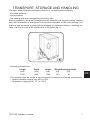
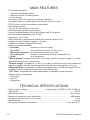
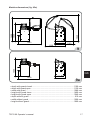
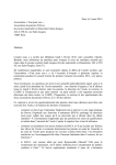
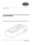
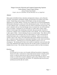
Automotive Equipment
OPERATOR’S MANUAL
WHEEL BALANCING MACHINE
TECO 66
Gb
Versione 3.0 del 12/09
MADE IN ITALY
CORREGGIO - R.E.
I
diritti di traduzione, di memorizzazione elettronica, di
riproduzione e di adattamento totale o parziale con qualsiasi mezzo (compresi microfilm e copie fotostatiche) sono
riservati.
Le informazioni contenute in questo manuale sono soggette a
variazioni senza preavviso.
A
ll rights reserved. No part of this publication may be
translated, stored in an electronic retrieval system, reproduced, or partially or totally adapted by any means (including
microfilm and photostats) without prior permission.
The information contained herein may be subject to modifications without prior notice.
L
es droits de traduction, de mémorisation électronique, de
reproduction et d’adaptation complète ou partielle par tout
type de moyen (y compris microfilms et copies photostatiques)
sont réservés.
Les informations fournies dans ce manuel peuvent être modifiées à tout moment et sans préavis.
A
lle Rechte der Übersetzung, der Speicherung, Reproduk
tion sowie der gesamten oder teilweisen Anpassung durch
ein beliebiges Mittel (einschließlich Mikrofilm und Fotokopien)
sind vorbehalten.
Die in diesem Handbuch enthaltenen Informationen können
ohne Vorbescheid geändert werden.
R
eservados los derechos de traducción, grabación
electrónica, reproducción y adaptación total o parcial con
cualquier medio (incluidos microfilmes y copias fotostáticas).
Las informaciones contenidas en el presente manual pueden
sufrir variaciones sin aviso previo.
Italiano
English
Français
Deutsch
Español
Elaborazione grafica e impaginazione
Ufficio Pubblicazioni Tecniche
2
TECO 66 Operator’s manual
EC declaration of conformity
We, TECO srl via Pio La torre 10, 42015 Correggio (RE), ITALY ,
do hereby declare, that the product
Wheel balancer
to which this statement refers, manufactured by us and for which
we hold the relative technical dossier, is compliant with the following
standards:
- EN ISO 12100-1; EN ISO 12100-2
- EN 60204-1
with reference to EC directives:
- 2006/42/CE
- 2006/95/CE;
- 2004/108/CE.
Gb
Correggio, 12 / 2009
.......................................
TECO srl
Barbetti Ing. Mauro
IMPORTANT: The EC Conformity Declaration is cancelled if the machine is not
used exclusively with TECO, original accessories and/or in observance of the
instructions contained in the user’s manual.
The form of this statement conforms to EN 45014 specifications.
TECO 66 Operator’s manual
3
4
TECO 66 Operator’s manual
ORIGINAL INSTRUCTIONS
CONTENTS
INTRODUCTION ......................................................................... 6
TRANSPORT, STORAGE AND HANDLING ............................... 7
INSTALLATION ........................................................................... 9
ELECTRICAL HOOK-UP ........................................................... 13
SAFETY REGULATIONS .......................................................... 14
MAIN FEATURES...................................................................... 16
TECHNICAL SPECIFICATIONS................................................ 16
EQUIPMENT ............................................................................. 18
OPTIONAL ACCESSORIES SUPPLIED ON REQUEST .......... 18
GENERAL CONDITIONS OF USE ........................................... 19
SWITCHING ON THE MACHINE .............................................. 20
WHEEL DATA ENTRY ............................................................... 21
UNBALANCE DISPLAY IN GRAMS / OUNCES ....................... 23
ROUNDING-OFF ...................................................................... 23
WHEEL SPIN ............................................................................ 24
WHEEL SPIN (with guard) ........................................................ 24
BALANCING PROGRAMMES .................................................. 25
FLASH OPT OPTIMISATION PROGRAMME ........................... 34
CALIBRATION PROGRAMMES ............................................... 37
DISPLAY MESSAGES .............................................................. 38
CHECK FOR CORRECT FUNCTIONING OF BALANCING
ACCESSORIES .................................................................... 39
TROUBLESHOOTING .............................................................. 40
MAINTENANCE ........................................................................ 42
SCRAPPING ............................................................................. 42
ENVIRONMENTAL INFORMATION .......................................... 43
FIRE-EXTINGUISHING MATERIALS TO BE USED ................. 44
GLOSSARY ............................................................................... 44
ELECTRICAL SYSTEM GENERAL DIAGRAM ......................... 45
TECO 66 Operator’s manual
Gb
5
INTRODUCTION
The purpose of this manual is to provide the owner and operator with effective and safe
instructions for the use and maintenance of the wheel balancer.
Follow all of the instructions carefully and your machine will assist you in your work and
give long-lasting and efficient service, in keeping with manufacturer traditions.
The following paragraphs define the levels of danger regarding the machine, associated
with the warning captions found in this manual.
DANGER
Refers to immediate dangers that result in serious injuries or even death.
WARNING
Refers to dangers or procedures that are not totally safe and that could result in
serious injuries or death.
ATTENTION
Dangers or unsafe procedures that can cause minor injuries or damage to property.
Read these instructions carefully before operating the machine. Keep this manual and the
illustrated materials supplied with the equipment in a folder near the place of operation
so as to allow the machine operators to consult the documentation at any time.
The technical documentation supplied is considered an integral part of the machine and
must always accompany the equipment if it is sold or transferred to a new owner.
The manual is only to be considered valid for the machine serial number and model
stated on the attached nameplate.
WARNING
The instructions and information described in this manual must always be complied with: the operator will be held responsible for any operation not specifically
described and authorised in this manual.
NOTE
Some of the illustrations contained in this booklet have been taken from pictures of
prototypes: standard production machines may differ slightly in certain respects.
These instructions are for the attention of personnel with basic mechanical skills. We have
therefore condensed the descriptions of each operation by omitting detailed instructions
regarding, for example, how to loosen or tighten the fixing devices. Do not attempt to
perform operations unless properly qualified or with suitable experience. If necessary,
please contact an authorised Service Centre for assistance.
6
TECO 66 Operator’s manual
TRANSPORT, STORAGE AND HANDLING
The basic wheel balancer packaging consists of 1 wooden crate containing:
- the wheel balancer ;
- the equipment;
- the wheel guard and corresponding mounting tube.
Before installation, the wheel balancer must be shipped in its original packing, making
sure that the machine is maintained in the position indicated on the outer packing. The
machine can be moved by placing the packaging on a wheeled trolley or inserting the
forks of a fork lift truck in the relative slots in the pallet (fig. 1).
1
- Packaging dimensions:
Length
(mm)
Depth
(mm)
Height
(mm)
1150
990
1360
Weight Packaging weight
(kg)
(kg)
120
Gb
30
- The machine must be stored in an environment meeting the following requirements:
• relative humidity ranging from 20% to 95%;
• temperature ranging from -10° to +60°C.
TECO 66 Operator’s manual
7
CAUTION
Do not stack more than two packs to avoid damaging them.
After installation, the machine can be moved using the following methods:
- with a crane, using special equipment that holds the machine at the designated lifting
points (fig. 2);
- by inserting the forks of a lift truck under the machine so that the centre of the forks
correspond approximately to the centre line of the body (fig. 3).
2
3
WARNING
Always unplug the power supply cable from the socket before moving the machine.
CAUTION
Never apply force to the wheel spin shaft when moving the machine.
8
TECO 66 Operator’s manual
INSTALLATION
WARNING
Take the utmost care when unpacking, assembling, lifting and setting up the
machine as indicated below.
Failure to observe these instructions can damage the machine and compromise
the operator's safety.
Remove the original packing material, after having positioned it as shown on the outside and keep intact so that the machine can be safely shipped at a later date if
necessary.
WARNING
All regulations in force concerning safety at work must be respected when choosing the installation position.
In particular, the machine must only be installed and operated in protected environments where there is no risk of exposure to dripping.
IMPORTANT: for the correct and safe operation of the machine, the lighting level in the
place of use should be at least 300 lux.
The floor must be strong enough to support a load equal to the weight of the equipment
plus the maximum load allowed. The support base on the floor and the envisaged fixing
means must also be taken into account.
Environmental operating conditions must comply with the following requirements:
- relative humidity ranging from 30% to 80% (without condensation);
- temperature ranging from 0° to +50°C.
CAUTION
For information concerning the technical features, warnings and maintenance
instructions consult the related operator manuals provided with the documentation of the machine.
WARNING
The machine must not be operated in potentially explosive atmospheres.
The machine is supplied partially disassembled and is to be assembled according to the
procedures described below.
TECO 66 Operator’s manual
9
Gb
Installing the wheel guard with the corresponding mounting (fig.4)
- Assemble the guard support on the pin that is on the swinging unit side of the body;
- turn the support until the holes on the support itself are aligned with those on the pin;
then fix the two parts using the included screw (fig.4);
- insert the metal tube (D, fig. 4a) into the two plastic guard front holes (C, fig. 4a);
- couple the guard to the rear side of the tube by inserting it into the correct position with
snap-in coupling (E, fig. 4a);
- secure the wheel guard by tightening the screw provided (F, fig. 4a).
4
4a
Fixing the machine to the ground (fig.6)
1500
600
600
Before fixing the machine to the ground, position it in its preselected location making
sure that the surrounding spaces are at least those indicated in figure 5/5a.
600
600
600
300
1500
1000
5
10
5a
TECO 66 Operator’s manual
- Fix the machine to the ground using the supplied kit on the rear side and on the flange
support side, as shown in the figure.
- In the case of a triangular foot (see accessories) the machine must only be fixed to the
ground if wheels are to be balanced that weigh more than or equal to 50Kg.
6
Main working parts (fig.7)
D
I
I
J
E
Gb
A
F
G
7
(A)
(D)
(E)
(F)
(G)
(I)
(J)
automatic diameter and distance measuring arm
display panel
flange holder
weight tray
wheel support shaft
handling holes
wheel guard
TECO 66 Operator’s manual
11
Display panel (fig. 8)
K
G
C
D
A
B
G
L
G
H
I
E
F
8
(A)
(B)
(C)
(D)
(E)
(F)
(G)
(H)
(I)
(J)
(K)
12
inner side display (left-hand)
outer side display (right-hand)
inner side position indicator
outer side position indicator
START key
STOP key
keys and indicator lights for selection of the functions and programmes available
key for manual input of the wheel geometric data
function key
indicator light for wheel geometric data setting
indicator light for unbalance display status
TECO 66 Operator’s manual
ELECTRICAL HOOK-UP
On request, the wheel balancer can be set up by the manufacturer to operate with the
power supply available in the place of installation. The set-up data for each machine are
given on the machine data plate and on a special label attached to the power supply
connection cable.
WARNING
Any operations for connecting the workshop electrical board must be carried out
only by qualified technicians in compliance with the regulations in force, under
the responsibility and at the charge of the customer.
The electric hook-up must be performed according to:
• the machine electric power as indicated on the machine data plate;
• the distance between the machine and the electric hook-up point, so that voltage
drops under full load do not exceed 4% (10% when starting up) of the rated voltage
specified on the data plate.
- The user must:
• fit a plug that respects the current regulations onto the power supply cable;
• connect the machine to its own electrical connection fitted with a suitable 30-mA
current sensitive circuit breaker;
• fit power supply protection fuses sized in compliance with specifications in the main
wiring diagram of this manual;
• provide the workshop electric installation with an efficient grounding circuit.
- Prevent unauthorised use of the machine, always disconnect the power supply plug
when the machine is not used (switched off) for extended periods of time.
- If the machine is connected directly to the power supply by means of the main electrical
board and without the use of a plug, install a key-operated switch or suitable lock-out
device to restrict machine use exclusively to qualified personnel.
WARNING
A good grounding connection is essential for correct operation of the machine.
NEVER connect the machine ground wire to a gas pipe, water pipe, telephone
cable or any other unsuitable object.
TECO 66 Operator’s manual
13
Gb
SAFETY REGULATIONS
WARNING
Failure to comply with the instructions and danger warnings can cause serious
injuries to the operator or other persons.
Do not operate the machine until you have read and understood all the danger/
warning notices in this manual.
The correct use of this machine requires a qualified and authorised operator. This operator must be able to understand the manufacturer written instructions, be suitably trained
and be familiar with the safety procedures and regulations. Operators are forbidden
from using the machine under the influence of alcohol or drugs that could affect his/her
physical and mental capacity.
The following conditions are essential under any circumstances:
- read and understand the information and instructions described in this manual;
- have a thorough knowledge of the features and characteristics of the machine;
- keep unauthorised persons well clear of the working area;
- make sure that the machine has been installed in compliance with all relevant standards
and regulations in force;
- make sure that all machine operators are suitably trained, that they are capable of using the machine correctly and safely and that they are adequately supervised during
work;
- do not touch power lines or the inside of electric motors or any other electrical equipment before making sure that they have been powered off;
- read this booklet carefully and learn how to use the machine correctly and safely;
- always keep this user manual in a place where it can be readily consulted and do not
fail to refer to it.
WARNING
Do not remove or deface the DANGER, WARNING, CAUTION or INSTRUCTION decals.
Replace any missing or illegible decals. If one or more decals have been detached
or damaged, they can be replaced by your nearest manufacturer dealer.
- When using and carrying out maintenance on the machine, observe the unified industrial accident prevention regulations for high voltage industrial equipment and rotating
machinery.
- Any unauthorised alterations made to the machine automatically release the manufacturer from any liability in the case of damage or accidents as a result of such alterations.
Specifically, tampering with or removing the machine’s safety devices is a breach of
the regulations for industrial accident prevention.
WARNING
During work and maintenance operations, always tie back long hair and do not
wear loose clothing, ties, necklaces, wristwatches or any other items that may get
caught up in the moving parts.
14
TECO 66 Operator’s manual
Key to caution and instruction labels
Never use the wheel spin shaft as a lifting point for the machine.
Unplug the power supply plug before performing any maintenance/
repair operations on the machine.
Do not lift up the guard when the wheel is turning.
Please use centring accessories with hole diameter 40 mm..
Gb
TECO 66 Operator’s manual
15
MAIN FEATURES
- Low balancing speed:
• minimises wheel spin times;
• reduces risk due to rotating parts;
• saves energy.
- Automatic sensor for measuring distance, diameter.
- Automatic brake for stopping the wheel at the end of the spin.
- STOP button to stop the machine immediately.
- Side flange holders.
- Top tray to take weights of all types.
- Automatic start by lowering the guard.
- Luminous digital display unit double display and 3D graphics.
- Microprocessor processing unit (16 bit).
- Resolution: 1g (1/10oz).
- Wide selection of programmes making the machine easy to use.
- Unbalance value display in grams or ounces.
- Unbalance display rounding-off setting.
- Balancing modes available:
• Standard
dynamic on both rim sides
• Alu / Alu P
seven different routines for alloy rims
• Motorcycle dynamic on both sides of motorcycle rims
• Alu motorcycle
dynamic on both sides of alloy motorcycle rims
• Static
on a single side.
- “Mobile planes” programme (in Alu P) for using multiple five gram weights, i.e.: available without the need for partial cuts.
- “Hidden weight” programme (in Alu P) in order to divide the outer side balancing
adhesive weights into two equal weights positioned behind the spokes of the rim.
- “Weight division” programme (motorcycle programmes) to divide the weight into two
equivalent values to be placed on either side of the spoke.
- “OPT flash” programme for rapid optimisation of operating noise reduction.
- General utility programmes:
• Calibration
• Service
• Diagnostics.
TECHNICAL SPECIFICATIONS
- Power supply voltage .................................. single-phase 115/230 V ±10%, 50/60 Hz
- Total power ....................................................................................................... 100 W
- Balancing speed ........................................................................................ 90/130 rpm
- Maximum unbalance value calculated ........................................................999 grams
- Average spin time (with 5”x14” wheel) ................................................................ 7 sec
- Shaft diameter ..................................................................................................40 mm
- Working environment temperature ...................................................... from 0 to 50°C
16
TECO 66 Operator’s manual
1540
1400
1060
Machine dimensions (fig. 9/9a)
585
1280
1100
1130
1060
9
Gb
1200
610
9a
• depth with guard closed ..............................................................................1100 mm
• depth with guard open ................................................................................1130 mm
• width with guard ..........................................................................................1280 mm
• height with guard close ...............................................................................1400 mm
• height with guard open ...............................................................................1540 mm
• depth without guard ......................................................................................610 mm
• width without guard .....................................................................................1200 mm
• height without guard....................................................................................1060 mm
TECO 66 Operator’s manual
17
Working range
• settable rim width ..............................................................................from 1.5" to 20"
• rim diameter measurable with the sensor ............................................ from 1” to 28”
• settable rim diameter ...........................................................................from 1" to 35"
• max. wheel/machine distance .......................................................................360 mm
• max. wheel width (with guard) ......................................................................600 mm
• max. wheel diameter (with guard) ............................................................... 1117 mm
- Max. wheel weight ..............................................................................................75 kg
- Overall weight (without accessories) ................................................................. 75 Kg
- Noise level in operation ............................................................. < 70 dB(A) ± 3 dB(A)
EQUIPMENT
Following parts are supplied together with the machine.
- Weight pliers.............................................................................................. 049700400
- Threaded hub .............................................................................................. 5-101514
- Caliper for wheel width measurement ....................................................... 100004200
- Open wrench CH 10 ........................................................................................ 442175
- Hexagon wrench CH 3 ................................................................................... 2-00673
- Hexagon wrench CH 4 ................................................................................... 2-00714
- Hexagon wrench CH 6 .................................................................................... 600906
- Hexagon wrench CH 10 .................................................................................. 600910
- IC screwdriver .............................................................................................. 4-101252
- 100 g weight ............................................................................................. 040009600
- Power supply cable ........................................................................................ 3-01943
OPTIONAL ACCESSORIES SUPPLIED ON
REQUEST
Please refer to relevant accessories catalogue.
18
TECO 66 Operator’s manual
GENERAL CONDITIONS OF USE
The machine is intended for professional use only.
WARNING
Only one operator at a time can work with the machine.
The wheel balancers described in this manual must be used exclusively to measure the
extent and position of car wheel unbalances, within the limits specified in the Technical
specification section. Furthermore, models equipped with motors must be provided with
a suitable guard, fitted with a safety device, which must be lowered during the wheel
spin operation.
WARNING
Any use other than those described in this manual is to be considered improper
and unreasonable.
CAUTION
Do not start the machine without the wheel locking equipment.
WARNING
Do not use the machine without the guard and do not tamper with the safety
device.
CAUTION
Do not clean or wash the wheels mounted on the machine with compressed air
or jets of water.
WARNING
When working, never use equipment not manufactured by the manufacturer.
Gb
WARNING
Get to know your machine. The best way to prevent accidents and obtain top
performance from the machine is to ensure that all operators know how the machine works.
Learn the function and location of all the controls.
Carefully check that all controls on the machine are working properly.
The machine must be installed properly, operated correctly and serviced regularly
in order to prevent accidents and injuries.
TECO 66 Operator’s manual
19
SWITCHING ON THE MACHINE
Connect the power supply cable (A, fig. 9b) supplied with the machine from the external
electrical panel located on the rear side of the wheel balancer body to the mains.
Switch on the machine using the switch on the rear side of the body (B, fig. 9b).
9b
The wheel balancer performs a checking test (all the LEDs illuminate), and if no faults are
detected, a beeper sounds and the cycle status initially active is displayed, as follows:
- active balancing mode: dynamic (DYN);
- values displayed: 000 000;
- grams displayed in units of 5 ( or 1/4 of an ounce);
- default geometric values: width = 5.5”, diameter = 14”, distance = 150 mm.
Now the operator can set the data of the wheel to be balanced or select one of the
programmes available.
20
TECO 66 Operator’s manual
WHEEL DATA ENTRY
The machine allows for the diameter and distance values to be entered automatically;
the width value can be entered using the keypad.
- Move the automatic measuring arm (A, fig. 7) so it comes into contact with the inner
side of the rim as shown in fig. 10/10a.
10
10a
Take great care to position the arm correctly so as to ensure accurate data reading.
- Keep the arm in contact with the rim until the machine has acquired the wheel's diameter
and distance values. The geometric data are displayed in sequence:
• d
distance value;
• di
diameter value.
When a geometric value is displayed, the corresponding LED illuminates on the display
panel.
- Check the values measured and then return the arm to the rest position. The machine
now presets for WIDTH measurement.
If an incorrect value has been acquired during the measurement phase, move the arm
to the rest position and then repeat the operation.
TECO 66 Operator’s manual
21
Gb
- Measure the width of the rim using the caliper provided (fig. 11).
11
- Modify the width value displayed by pressing the keys
until the desired
number is set.
The WIDTH can be set in millimetres or the values already set can be converted from
inches to millimetres by pressing the
Keep the
values.
button.
keys pressed to rapidly increase or decrease the previously set
Manual wheel data entry
In the event of failure of the automatic measuring system the geometrical data can be
entered using the keypad:
- Press the
button.
- Measure the width of the rim using the caliper provided (fig. 13).
until the desired
- Modify the width value displayed by pressing the keys
number is set. The width can be set in millimetres or the values already set can be
converted from inches to millimetres by pressing the
button.
- Values set previously can be increased or decreased quickly by keeping the keys
pressed.
- Press the
button to confirm the previous value and set the machine for diameter
data entry.
- Read the rated rim diameter value on the tyre.
22
TECO 66 Operator’s manual
- Modify the displayed diameter value by pressing the
buttons until the
read number is set. The diameter can be set in millimetres or the values already set
can be converted from inches to millimetres by pressing the
button.
button to confirm the previous value and set the machine for distance
- Press the
data entry.
- Bring the distance measuring arm into contact with the inner side of the rim (fig.
10/10a).
- Read the wheel/body distance on the rule.
- Modify the displayed distance value by pressing the
number is set.
- On completion, press
buttons until the read
to display the unbalance values recalculated on the basis
to perform a wheel spin.
of the new dimensions, or
UNBALANCE DISPLAY IN
GRAMS / OUNCES
The setting for the display of the unbalance values in grammes or ounces is made by
keeping the key
pressed for about five seconds.
ROUNDING-OFF
When started up, the machine is set to display the unbalance values at five-gramme
increments, i.e. rounded to the nearest multiple of five (or quarters of an ounce if visualised in ounces).
In this condition, the first four grams of unbalance are not displayed since an appropriate threshold, indicated by illumination of the
activated.
LED on the display panel, is
The
key can be pressed to eliminate the threshold (the illuminated indication “x5”;
“oz/4” goes out) and the unbalance values will be displayed gram by gram (or in tenths
of an ounce if display in ounces is active).
Pressing the key consecutively allows the user to set one display mode or the other.
TECO 66 Operator’s manual
23
Gb
WHEEL SPIN
Press the
key on the display and the button on the left side and hold them down
until the braking phase starts. If one of the two contacts, or both, is released during the
wheel start-up or reading phase, the message “A Cr” will appear and the brake will be
automatically activated.
WARNING
Do not operate the machine if the safety device has been tampered with.
WARNING
During machine use, personnel may not be present in the area enclosed by the
sectioning in fig.5a.
WHEEL SPIN (with guard)
Wheel spin takes place automatically when the guard is lowered, or can be triggered by
pressing the START key with the guard lowered.
A special safety device stops rotation if the guard is raised during the wheel spin; in this
case, the “A Cr” message is displayed.
WARNING
Do not operate the machine without the guard and/or if the safety device has been
tampered with.
WARNING
Never raise the guard before the wheel has come to a stop.
WARNING
If the wheel keeps spinning permanently due to a fault on the machine, switch off
the machine using the main switch or disconnect the plug from the power supply
board (emergency stop) and wait until the wheel stops before raising the guard.
24
TECO 66 Operator’s manual
BALANCING PROGRAMMES
Before starting a balancing operation, it is necessary to:
- fit the wheel on the hub using the most suitable flange;
- lock the wheel so that no movement is possible during the wheel spin and braking
phases;
- remove any counterweight, pebble, dirt or other foreign body;
- set the wheel's geometric data correctly.
Dynamic balancing (standard)
Proceed as follows to balance a wheel in dynamic mode:
- Press the
and keys until the LED corresponding to the DYN programme
illuminates.
to confirm the selection.
- Press the key
This programme is automatically launched when the machine is switched on.
- Set the wheel's geometric data.
- Spin the wheel by lowering the guard.
To obtain the most accurate results, do not apply any undue stress to the machine
during wheel spin.
- Wait for the wheel to stop automatically and for the calculated unbalance values to be
displayed.
- Select the first side to be balanced.
- Turn the wheel until the central element of the corresponding position indicator lights up.
- Apply the indicated balancing weight in the position on the rim corresponding to
12 o'clock.
- Repeat the operations listed above for the second side of the wheel.
- Perform a test wheel spin to check the balancing accuracy. If it is not satisfactory, modify
the value and position of the weights previously applied.
Bear in mind that a counterweight positioning error of just a few degrees may lead to a
residual unbalance as large as 5-10 grams during the verification phase, especially in
the case of large unbalances.
WARNING
Check that the system which fits the weight to the rim is in optimum condition.
A weight which is not fitted properly or correctly may come off as the wheel rotates,
thus creating a potential danger.
key is pressed whilst the wheel is rotating, the spin will be prematurely
If the
interrupted.
TECO 66 Operator’s manual
25
Gb
Static balancing
A wheel can be balanced using a single counterweight on one of its two sides or in the
centre of the well. In this case, the wheel is balanced statically. However, there is still the
risk of dynamic unbalance, which becomes more significant as the width of the wheel
increases.
- Press the
and keys until the LED corresponding to the STATIC programme
illuminates;
button to confirm selection;
- press the
- set the wheel diameter value (in static mode it is not necessary to enter the width and
distance values);
- spin the wheel by lowering the guard;
- wait for the wheel to stop automatically and for the calculated static unbalance value
to be displayed;
- rotate the wheel until the central element of the position indicator lights up;
- apply the balancing weight in the 12 o'clock position on either the outer or inner side,
or at the centre of the rim well, indifferently. If applied in the well, the weight is applied
on a diameter smaller than the rated diameter of the rim. A value of 2 or 3 inches less
than the rated value must therefore be entered when the diameter is set in order to
obtain correct results;
- follow the instructions specified in the dynamic balancing procedure to perform a test
wheel spin.
Alloy wheel balancing (ALU)
Self-adhesive weights are generally used to balance alloy wheels and are applied differently than for standard balancing (fig. 12).).
12
Several ALU balancing programmes are available, specially designed for these types
of rim.
ALU programmes can be selected as follows:
- Press the
illuminates.
keys until the LED corresponding to the ALU programme
key as often as necessary to confirm selection of the Alu programme
- Press the
desired (the corresponding balancing planes are highlighted on the rim shown on the
control panel).
26
TECO 66 Operator’s manual
ALU programmes 1P, 2P
These programmes are used for maximum precision balancing of light alloy rims that require
both weights to be applied on the same side (inner) in relation to the rim disk.
This type of wheel balancer is particularly suitable for application of adhesive weights on
the rim, thanks to the forward position of the wheel in relation to the body, which allows
a large zone on the inside of the rim to be accessed freely.
After selecting the desired ALU P programme, the wheel data must be acquired.
Wheel data acquisition
Geometric data relating to the actual balancing planes rather than the rated wheel
data (as in standard ALU programmes) have to be set. The balancing planes where
the adhesive weights are to be applied may be selected by the user according to the
specific shape of the rim. It should be remembered, however, that in order to reduce the
quantity of the weights to be applied it is better to select balancing planes placed as
far apart as possible; if the distance between the two planes is less than 37 mm (1.5”),
the “A 5” message is displayed.
- Move the end of the automatic measuring arm in line with the plane selected for the
application of the inner weight. In Alu 1 P, the centre of the pawl on the end section of
the lever is taken as a reference for the centre line of the weight (version without the
weight holding device). In versions with the weight holding device, the centre line of the
weight must correspond with the centre of the groove in which the weight will be placed.
(fig. 13/13a)
Gb
13
13a
- In Alu 2 P refer to the rim edge, since the inner weight is of the traditional clip type (fig. 10/10a).
Pay maximum attention when the end of the arm is being placed in an area of
the rim free of discontinuity, so that the weight can be applied in that position.
- Keep the arm in position. After two seconds the machine emits an acoustic confirmation
signal to indicate that the distance and diameter values have been acquired.
- Move the end of the automatic measuring arm in correspondence with the plane selected
for the application of the outside balancing weight (fig. 14/14a), in the same manner
as described previously for the inner side.
TECO 66 Operator’s manual
27
14
14a
- Keep the arm in position and wait for the acoustic confirmation signal.
- Return the measuring arm to the rest position.
If the measuring arm is returned to the rest position after acquiring the data relating to
only one plane or if first the outer plane data then the inner plate data are acquired, the
“A 23” message is displayed and the acquired data are not considered.
- Carry out a spin
Applying balancing weights. (fig.15)
- Select the plane where the first balancing weight is to be applied.
- Turn the wheel until the central element of the corresponding position indicator lights up.
If the weight to apply is of the traditional clip type (inner side in Alu 2P), position it at
12 o'clock. If, on the other hand, the weight to be applied is of the adhesive type and
there is a weight holder device, proceed as follows:
- Position it inside the grove of the weight-holder terminal of the measuring arm (fig.
15,a,b), with the guard paper of the adhesive band facing upwards. Then remove the
paper (fig. 15c).
28
TECO 66 Operator’s manual
a
b
c
d
e
15
- move the sensor until it reaches the indicated position. In this phase, one display continues to show the unbalance value of the side to be balanced, while the other shows
a numerical value updated on the basis of the sensor position, which becomes zero
when the position for application of the weight is reached.
- Turn the end of the measuring arm until the weight adhesive strip is in line with the rim
surface.
- Press the button (fig. 15d) to eject the weight and make it stick to the rim.
- Return the measuring arm to the rest position (fig.15e).
- Repeat the operations to apply the second balancing weight.
- Perform a test wheel spin to check the balancing accuracy.
The rim surface must be perfectly clean to make the weight stick efficiently to the rim. If
necessary, clean the surface using suitable cleansing products.
In the machine versions without a weight-holding device proceed as follows:
- Select the plane where the first balancing weight is to be applied.
- Turn the wheel until the central element of the corresponding position indicator lights up.
- Apply the adhesive weight manually in the position in which the relative plane was
measured.
“Mobile planes” programme (available only with Alu p programmes)
This function is automatically enabled when an ALU P programme is selected.
It modifies the selected positions for the application of adhesive weights, so as
to ensure perfect balancing of the wheel using commercially available adhesive
weights (i.e. multiples of five grams). The accuracy of the machine is thereby improved, avoiding rounding off or cutting the weights to be applied to come closer to the
actual unbalance values.
The modified positions, where the adhesive weights are to be applied, are identified by
the user according to the information given by the wheel balancer (see the BALANCING
WEIGHT APPLICATION section).
TECO 66 Operator’s manual
29
Gb
“Hidden weight” programme (available only with Alu p programmes)
This programme divides the outer balancing weight into two equal weights placed in
hidden positions behind two spokes of the alloy rim.
- Select in advance one of the programmes, ALU 1 P or ALU 2 P.
keys until the LED corresponding to the programme
- Press the
illuminates.
- Press the key
to confirm the selection.
This accesses the “hidden weight” programme, and the message “hid” appears on the
left-hand display. If the user tries to select this programme without previously selecting
an ALU P programme, the “A 26” message is displayed.
keys until the number of spokes in the rim appears on the
- Press the
right-hand display.
- Turn the wheel until the centre of a spoke reaches the 12 o'clock position.
to save the data entered (number of spokes and angular position) and
- Press
exit the data setting environment to go back to the previously selected ALUP programme.
- The LED
remains on to indicate that the “hidden weight” programme is active.
- OFF can be selected instead of a number of spokes to disable the programme selected
previously, or to exit without activating it.
- Carry out a spin.
The two unbalance values calculated will appear in alternation on the display relating to
the outer side, as the angular position of the wheel varies.
Each of the two outer side balancing weights is applied as described in the Alu P programme “BALANCING WEIGHT APPLICATION” section.
The HIDDEN WEIGHT function is combined with the MOBILE PLANES function to allow
balancing weights which are multiples of 5 grams to be used.
Standard ALU programmes (ALU 1, 2, 3, 4, 5)
The standard ALU programmes allow for the various modes of application of the weights
(fig.12) and supply correct unbalance values maintaining the settings of the rated geometric alloy wheel data.
- Press the
and keys until the LED corresponding to the ALU programme
illuminates.
30
TECO 66 Operator’s manual
- Press the
button as many times as necessary to confirm the selection of the Alu
programme desired (the corresponding balancing planes are highlighted on the rim
shown on the display).
- Set the rated geometric data.
If the values of the diameter and of the distance between the balancing planes, recalculated on a statistical basis starting from the rated geometric data of the wheel, exceed
the normally accepted interval stated in the TECHNICAL DATA section, the “A Alu”
message is displayed.
- Proceed as described for dynamic balancing.
Some slight residual unbalances may remain at the end of the test spin due to the
considerable difference in shape that may be found on rims having the same rated
dimensions. Therefore modify the value and position the previously applied weights for
accurate wheel balancing.
Motorcycle wheel balancing
Motorcycle wheels can be balanced in:
- Dynamic mode; when the wheel width is such (over 3 inches) to generate significant
unbalance components which cannot be eliminated with static balancing (the recommended procedure).
- Dynamic mode for alloy rims; a programme similar to the ALU programmes for car
wheels.
- Static mode; JUST ONE BALANCING WEIGHT, DIVIDED, IF NECESSARY, INTO
EQUAL PARTS ON THE TWO SIDES; PROCEDURE DESCRIBED IN THE Static
Balancing section.
Motorcycle Dynamic programme
Proceed as follows to balance a motorcycle wheel on two planes (dynamic balancing)
using clip weights:
- fit the motorcycle wheel adapter on the wheel balancer as shown in fig.17;
TECO 66 Operator’s manual
31
Gb
17
17a
- insert the two screws that are supplied in the holes on the wheel contact flange;
- tighten the screws on the adapter making sure that it rests on the flange correctly;
- fit the most suitable pin (depending on the wheel central hole) onto the shaft after
removing the threaded hub;
- mount the wheel after selecting the centring cones (one for each side of the wheel),
tighten with the appropriate ring nut using the spacers necessary for coupling the securing cones to the threaded part of the shaft.
IMPORTANT: The wheel must be fixed to the flange so as to avoid any movement of
the two during the spin or braking phases.
- Press the
illuminates.
keys until the LED corresponding to the programme
- Press the key
to confirm the selection.
- Mount the specific extension on the inner measuring arm, i.e. A if the weight-holder
device is not installed, B if the weight holder device is installed (fig.17 a).
Remember to remove this extension before performing the wheel spin.
- Set the wheel data as usual.
- Proceed as described for dynamic balancing.
32
TECO 66 Operator’s manual
Motorcycle ALU programme
Proceed as follows to balance motorcycle wheels dynamically using adhesive
weights:
- Press the
illuminates.
keys until the LED corresponding to the programme
button twice to select “Motorcycle Alu” programme (the correspond- Press the
ing balancing planes are highlighted on the rim shown on the control panel).
- Proceed as described previously for the “Motorcycle Dynamic” programme.
Best results can be achieved if the adhesive weights are positioned with the outer edge
flush with the rim edge.
Weight Division programme (available only with Motorcycle
programmes)
Some rims have spokes so wide that it is not possible to place adhesive weights next to
them; a programme which divides the counterweights into two parts has been introduced
to solve this problem.
In this case, when the centred position is reached and it becomes obvious that the balancing weight will have to be applied in line with a spoke, proceed as follows:
- remain in the centred position;
- press
;
keys to select the width of the spoke:
- use the
• 1 = small
• 2 = medium
• 3 = large
• OFF = deactivates the programme;
Gb
- confirm with the
key;
- apply two new counterweights in the positions indicated.
In “ALU MOTO” and “dynamic” modes it is possible to divide the balancing weights
over both sides of the wheel to be balanced.
TECO 66 Operator’s manual
33
FLASH OPT OPTIMISATION PROGRAMME
This procedure minimises any vibration still present on the vehicle while running even
after accurate balancing, thus minimising the rim-tyre coupling run-out.
The professional experience of the tyre specialist is extremely important in these cases.
If it is decided that this extra step could be helpful to reduce road noise to a minimum,
this programme can be selected.
The calculations performed by this programme are based on the unbalance values
measured during the last wheel spin performed which must therefore refer to the wheel
being serviced.
Proceed as follows to recall this programme:
and keys until the LED corresponding to the OPT programme
- Press the
illuminates.
to confirm the selection.
- Press the key
Once the selection has been made, the machine will indicate whether it is convenient to
proceed with the programme. To do this the machine will flash the following message:
• “YES OPT” if it is worth executing the programme;
• “NO OPT” in the opposite case.
key to exit from the programme and return to the DYN environment.
Press the
When the procedure is recalled, the left-hand display will show: “OP.1”.
OPT 1
- Take the valve to 12 o'clock.
- Confirm by pressing
the button.
OPT 2
- Turn the wheel until you reach the position indicated by the illuminated central elements
of the position indicator.
- Mark the 12 o'clock position on the outer tyre side using a piece of chalk.
- Press the
button.
key is pressed now, the system temporarily exits from the OPT programme
- If the
(to return, repeat the initial OPT programme activation procedure).
- Disassemble the wheel from the wheel balancer.
- Turn the tyre on the rim until the chalk mark is in line with the valve (180° rotation).
- Remount the wheel on the wheel balancer.
- Turn the wheel until the valve is in the 12 o'clock position.
- Press the
button.
- Carry out a spin.
34
TECO 66 Operator’s manual
The improvement preview can be displayed before continuing with the last phase of
the optimisation procedure. If the improvement is considered insufficient or if no further
significant improvements can be achieved, press the
button to exit.
Proceed as follows to display the improvement that can be achieved:
button once: the actual unbalance values of the wheel as currently
- press the
mounted on the wheel balancer are now shown on the displays;
- press the
button again: the unbalance values indicated on the displays are
the values that can be achieved by continuing with the last phase of the optimisation
procedure;
- when the
button is pressed for the third time, the machine prepares for the last
phase of the OPT programme.
OPT 3
- Rotate the wheel until you reach the position indicated by the illuminated central elements of the position indicator.
- Make a double mark on the outer side of the tyre in the 12 o'clock position using a
piece of chalk. If instructed to mount the tyre on the rim in the reverse direction, make
the double mark on the inner side. The user can switch from the “with reversal” to the
“without reversal” mode by pressing the
key.
button.
- Press the
- Disassemble the wheel from the wheel balancer.
- Turn the tyre (and reverse its mounting if necessary) on the rim until the double chalk
mark is in line with the valve.
- Remount the wheel on the wheel balancer.
- Press the
button to confirm the performed rotation.
- Carry out a spin.
When the spin is over the optimisation programme has been completed and the weights
to be applied to balance the wheel are displayed.
If an error that may affect the end result occurs, the machine indicates it by temporarily
displaying the “E 6” message. The procedure can now be repeated.
TECO 66 Operator’s manual
35
Gb
Special cases
- The “OUT 2” message can be displayed at the end of the first spin. In this case it is
: the values of the weights
advisable to exit the programme by pressing the key
necessary for balancing the wheel are displayed. The execution of the programme is
interrupted, thus not achieving the moderate improvement of the end results. By presskey the optimisation procedure can be continued.
ing the
- At the end of the first spin the instruction that the tyre is to be mounted on the rim in
the reverse direction may appear. If you do not intend to reverse the tyre or if doing so
is impossible, press the
key and the machine will provide the instructions for
completing the programme without reversing the tyre.
36
TECO 66 Operator’s manual
CALIBRATION PROGRAMMES
Sensitivity calibration
Calibrate when detecting that the setting condition is out-of-tolerance or when the machine so requires as the “E1” message is displayed.
- Fit a wheel of average dimensions (preferably with only small unbalance) on the wheel
balancer.
- Set the wheel geometric data correctly.
- Press the
keys until the luminous dot corresponding to the CAL programme
illuminates.
to confirm the selection.
- Press the key
- After the selection, the machine will display the message:
• CAL on the left-hand display;
• GO on the right-hand display.
- Perform a first spin.
- At the end of the spin, turn the wheel until it reaches the position marked by the position
indicator and the message “100” (“3.5” if the ounces view mode has been selected) is
displayed.
- Apply a sample weight of 100 grams (3.5 oz) to the INSIDE of the rim, at exactly 12
o’clock.
- Perform a second spin.
- At the end of the spin, remove the sample weight and turn the wheel until it reaches
the position marked by the position indicator and the message “100” (or “3.5”) is displayed.
- Apply the sample weight of 100 grams (3.5 oz) to the OUTSIDE of the rim, at exactly
12 o’clock.
- Perform a third spin.
This last calibration phase includes the execution of three consecutive spins in
automatic mode.
At the end of the spin(the message “End CAL" will appear on the display), if the
calibration has been successful, an acoustic consent signal goes off at the end of the
spin otherwise the message E 2 is temporarily displayed.
NOTES
- On completion of the procedure, remove the sample weight of 100 gr (3.5 oz).
- Pressing the key
, it is possible to interrupt the programme at any time.
- THE CALIBRATION DESCRIBED ABOVE IS VALID FOR ANY TYPE OF WHEEL!
TECO 66 Operator’s manual
37
Gb
DISPLAY MESSAGES
The machine can recognise a certain number of malfunction conditions and signals them
to the user by visualising the relevant messages on the display.
– A – notice messages
A3
A5
A7
A 10
A 23
A 26
A Stp
A Cr
Wheel not suitable for performing the sensitivity calibration, use a wheel of
average dimensions.
Incorrect dimension settings for an ALU programme. Correct the dimensions
that have been set.
The machine is not enabled temporarily to select the programme requested.
Perform a wheel spin, then repeat the request.
Internal sensor not in the rest position. Return the sensor to the rest position
(completely in). If the message does not disappear, internal sensor operation
button.
can be disabled by pressing the
Incomplete or incorrect data entry in ALU P.
Repeat the input correctly.
Programme available only after selecting one of the following programmes:
ALU 1P / ALU 2P / Motorcycle Dynamic / Alu Motorcycle or if selected in the
Motorcycle Programme but with the wheel NOT in the centred position.
Wheel stop during the spin phase.
Spin performed with the guard raised.
Lower the guard to perform the wheel spin.
– E – error messages
E1
E2
E4
E6
E 16
E 27
E 28
E 30
E 32
38
Absence of sensitivity calibration.
Perform the sensitivity calibration procedure.
Error condition on sensitivity calibration.
Repeat the sensitivity calibration procedure.
Distance-diameter sensor fault. Request assistance from technical support
service
Error condition when executing optimisation programme.
Repeat the procedure from the beginning.
Motor temperature too high. Wait before performing a new spin (do not
turn off the machine).
Excessive braking time. If the problem persists, call in the technical
support centre.
Encoder counting error. If the error occurs frequently, call in the technical
support centre.
Wheel spin device failure. Switch off the machine and call in the technical
support centre.
The wheel balancer has been jolted during the reading phase. Repeat the
wheel spin.
TECO 66 Operator’s manual
Other messages
CAL [GO] Calibration wheel spin.
GO Alu
Wheel spin with Alu programme selected.
GO d15
Wheel spin with Motorcycle Dynamic programme selected.
GO A15
Wheel spin with Alu Motorcycle programme selected.
St
Wheel spin with Static programme selected.
hid n
Setting of number of spokes in “hidden weight” programme.
CCC CCC Unbalance values greater than 999 grams.
CHECK FOR CORRECT FUNCTIONING OF
BALANCING ACCESSORIES
Checking balancing accessories allows the operator to make sure that wear has not altered
the mechanical specifications of flanges, cones, etc. beyond the specified limits.
A perfectly balanced wheel, which has been disassembled and reassembled in a different
position, should not show an unbalance value greater than 10 grams.
When a higher unbalance is found, check all the accessories carefully and replace the
components that are not in perfect condition (e.g. showing dents, abnormal wear, flange
unbalance, etc.).
Anyhow it is necessary to bear in mind that, if the cone is used to centre the wheel,
satisfactory balancing results cannot be achieved if the central hole of the wheel is outof-round or incorrectly centred; Better results can be achieved by centring the wheel
using the securing holes.
Bear in mind that any re-centring error made when the wheel is mounted on the car can
be removed only removed with an “on-the-vehicle balancing” of the wheel, using an onthe-vehicle wheel balancer to complement the work of the wheel balancer.
TECO 66 Operator’s manual
39
Gb
TROUBLESHOOTING
Below is a list of faults that may occur and that the user can solve if the cause is found
among those indicated.
For any other malfunction or fault call in the technical support centre.
The machine does not switch on(the displays remain switched off)
No power at the socket.
Check the mains voltage is present.
Check the electrical power circuit in the workshop.
The machine plug is defective.
Check that the plug is undamaged.
One of the FU1-FU2 fuses of the rear electrical panel has blown.
Replace the blown fuse.
The values of the dimensions measured with the automatic sensor do not
match the rated values of the rims
The sensors have not been positioned correctly during measurement.
Bring the sensor to the position shown in the manual and follow the instructions in
the WHEEL DATA ENTRY section.
The automatic sensor does not work
The sensor was not in the rest position at switch-on (A 10) and the
key has
been pressed to enter the wheel geometric data with the keypad, disabling control
of the automatic sensor.
fl
Switch off the machine, return the sensors to the correct position and switch back on.
Pressing the START key and the button
(only the START key if the guard is installed)
the wheel fails to spin (the machine does not start)
For machines with guard, check that it is not raised (the message “A Cr” appears).
fl
Lower the wheel guard.
For machines without guard, check that both the START key as well as the button on
the side of the machine have been pressed.
The wheel balancer provides unsteady unbalance values
The machine was jolted during the spin.
fl
Repeat the spin, taking care not to disturb the machine while measuring is in
progress.
The machine does not firmly rest on the floor.
fl
Make sure that the floor support is firm The wheel is not locked correctly.
fl
Tighten the securing ring nut correctly.
40
TECO 66 Operator’s manual
Several spins are to be performed to balance the wheel
The machine was jolted during the spin.
fl
Repeat the spin, taking care not to disturb the machine while measuring is in
progress.
The machine does not firmly rest on the floor.
fl
Make sure that the floor support is firm.
The wheel is not locked correctly.
fl
Tighten the securing ring nut correctly.
The machine has not been calibrated correctly.
fl
Carry out the sensitivity calibration procedure.
The entered geometric data are not correct.
fl
Check that the data corresponds to the dimensions of the wheel and correct, if
necessary.
WARNING
The “Spare parts” handbook does not authorise the user to carry out work on the
machine with the exception of those operations explicitly described in the User
Manual. It only enables the user to provide the technical assistance service with
precise information, to minimise delays.
Gb
TECO 66 Operator’s manual
41
MAINTENANCE
WARNING
The company is not to be held responsible for any claims deriving from the use
of non-original spare parts or accessories.
WARNING
Unplug the machine from the power supply and make sure that all moving parts
have been locked before performing any adjustment or maintenance operation.
Do not remove or modify any part of the machine (except for service interventions).
CAUTION
Keep the work area clean.
Never use compressed air and/or jets of water to remove dirt or residues from
the machine.
Take all possible measures to prevent dust from building up or raising during
cleaning operations.
Keep the wheel balancer shaft, the securing ring nut, the centring cones and flange clean.
These components can be cleaned using a brush previously dripped in environmentally
friendly solvents.
Handle cones and flanges carefully so as to avoid accidental dropping and subsequent
damage that would affect centring accuracy.
After use, store cones and flanges in a place where they are suitably protected from
dust and dirt.
If necessary, use ethyl alcohol to clean the display panel.
Perform the calibration procedure at least once every six months.
SCRAPPING
If the machine is to be scrapped, remove all electrical, electronic, plastic and ferrous
components and dispose of them separately, as provided for by local legislation.
42
TECO 66 Operator’s manual
ENVIRONMENTAL INFORMATION
The following disposal procedure must be applied to the machines having the crossed-out
bin symbol on their data plate
.
This product may contain substances that can be hazardous to the environment or to
human health if it is not disposed of properly.
The following information is therefore provided to prevent the release of these substances
and to improve the use of natural resources.
Electrical and electronic equipment must never be disposed of in the usual municipal
waste but must be separately collected for their proper treatment.
The crossed-out bin symbol, placed on the product and on this page, reminds the user
that the product must be disposed of properly at the end of its life.
Thus, the hazardous consequences that non-specific treatments of the substances contained in these products, or improper use of parts of them, may have on the environment
or on human health are prevented. Furthermore, this helps to recover, recycle and reuse
many of the materials contained in these products.
Electrical and electronic equipment manufacturers and distributors set up proper collection and treatment systems for these products for this purpose.
Contact your local distributor to obtain information on the collection procedures at the
end of the life of your product.
When purchasing this product, your distributor will also inform you of the possibility to
return another end-of-life piece of equipment free of charge as long as it is of equivalent
type and had the same functions as the purchased product.
Any disposal of the product performed in a different way from that described above will
be liable to the penalties provided for by the national regulations in force in the country
where the product is disposed of.
Further measures for environmental protection are recommended: recycling of the internal and external packaging of the product and proper disposal of used batteries (only
if contained in the product).
Your help is crucial to reduce the amount of natural resources used for manufacturing
electrical and electronic equipment, minimise the use of landfills for product disposal
and improve the quality of life, preventing potentially hazardous substances from being
released in the environment.
TECO 66 Operator’s manual
43
Gb
FIRE-EXTINGUISHING MATERIALS TO BE
USED
Consult the following table to choose the most suitable fire extinguisher.
Water
Foam
Powder
CO2
Dry materials
YES
YES
YES*
YES*
Flammable liquids
NO
YES
YES
YES
Electrical equipment
NO
NO
YES
YES
YES* Use only if more appropriate extinguishers are not at hand or when the fire
is small.
WARNING
This table contains general instructions to be used as guidelines for users. All
the applications of each type of extinguisher must be obtained from the relevant
manufacturer.
GLOSSARY
Below is a brief description of some technical terms used in this manual.
SELF-CALIBRATION
This procedure calculates suitable correction coefficients starting from known operating conditions. It improves the machine accuracy by correcting to a certain extent the
calculation errors that may result from the alteration of the machine's features over the
course of time.
CALIBRATION
See SELF-CALIBRATION.
CENTRING
Procedure for positioning the wheel on the wheel balancer shaft to ensure that the shaft
axis corresponds to the wheel rotation axis.
BALANCING CYCLE
Sequence of operations to be performed by the user and the machine from the beginning of
the wheel spin until the wheel is braked to a stop after calculating the unbalance values.
CONE
Conical element with a central hole which, when inserted on the wheel balancer shaft,
is used to centre the wheels having central holes with a diameter ranging between
maximum and minimum values..
DYNAMIC BALANCING
Procedure for unbalance compensation by applying two weights, one on each of the
two wheel sides.
STATIC BALANCING
Procedure for correcting only the static element of the unbalance, by applying only one
weight, usually at the centre of the rim well. Accuracy increases as the width of the
wheel decreases.
44
TECO 66 Operator’s manual
FLANGE (of the wheel balancer)
Circular crown-shaped disk against which the disk of the wheel mounted on the wheel
balancer rests. Also used for keeping the wheel perfectly perpendicular to its rotation
axis.
FLANGE (adapter - centring accessory)
Device for supporting and centring the wheel. Also used for keeping the wheel perfectly
perpendicular to its rotation axis.
Mounted on the shaft of the wheel balancer by means of the central bore.
RING NUT
Wheel blocking device on the wheel balancer, fitted with elements for coupling with the
threaded hub and side pins for tightening it.
SPIN
Procedure starting from the action that causes the wheel to rotate and the subsequent
rotation of the wheel.
THREADED HUB
Threaded part of the shaft on which the ring nut is engaged to lock the wheel. It is supplied disassembled from the machine.
UNBALANCE
Uneven distribution of the wheel mass that generates centrifugal forces during rotation.
SENSOR (measuring arm)
Mobile mechanical element that, when brought into contact with the rim in a specific
position, measures the geometric data: distance, diameter. Data can be measured automatically if the sensor is equipped with suitable measurement transducers.
ELECTRICAL SYSTEM GENERAL DIAGRAM
AP1
AP5
BP1
BP2
FU1
FU2
M1
QS1
SQ1
XS1
BR2
BR3
Feeder and control board
Search card
Internal pick-up
External pick-up
Fuse
Fuse
Motor
Main switch
Safety guard micro-switch
Power supply socket
Diameter measuring sensor
Distance measuring sensor
TECO 66 Operator’s manual
Gb
45
18
46
TECO 66 Operator’s manual
Note
Gb
TECO 66 Operator’s manual
47
®
Automotive Equipment
TECO s.r.l. Via Pio La Torre 10 - 42015 Correggio (R.E.)
ITALY tel. 0522/631562 - fax 0522/642373
Home Page : www.teco.it - E-mail : [email protected]