1
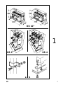
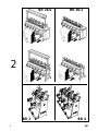
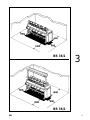
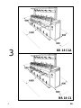
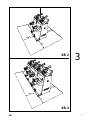
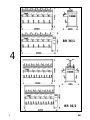
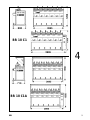
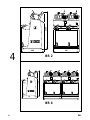
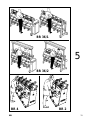
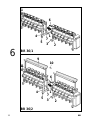
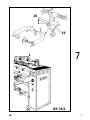
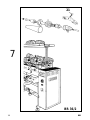
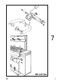
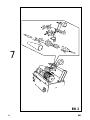
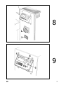
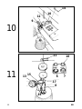
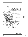
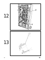
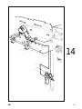
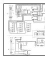
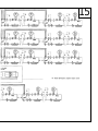
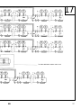
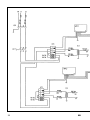
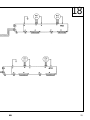
BR
Versione 5.1 del 03/01
Italiano
Manuale d’uso
English
Operator’s manual
Français
Manuel d’utilisation
Deutsch
Betriebsanleitung
Español
Manual de uso
INTRODUCTION
The purpose of this manual is to furnish the owner and operator of this Corghi machine
with a set of practical and safe instructions for the use and maintenance of the BR
hank-to-cone machine.
Follow all the instructions carefully and your balancer will assist you in your work and
give lasting and efficient service in keeping with CORGHI traditions.
The following paragraphs define the levels of danger regarding the machine associated
with the warning captions found in this manual:
DANGER
Refers to immediate danger with the risk of serious injury or death.
WARNING
Dangers or unsafe procedures that can cause serious injury or death.
ATTENTION
Dangers or unsafe procedures that can cause minor injuries or damage to property.
Read these instructions carefully before powering up the machine. Conserve this
manual and all illustrative material supplied with the machine in a folder near the tyre
changer where it is readily accessible for consultation by the machine operator.
The technical documentation supplied is considered an integral part of the machine;
in the event of sale all relative documentation must remain with the jack.
The manual is only valid for the machine model and serial number indicated on the
nameplate applied to the machine itself.
WARNING
Adhere to the contents of this manual: Corghi declines all liability in the case of
actions not specifically described and authorised in this manual.
NOTE
Some of the illustrations in this manual have been taken from photographs of prototypes; the standard production model may differ slightly in certain respects.
These instructions are meant for persons with a certain level of mechanical and
electrical expertise. We have therefore left out descriptions of simple operations, such
as methods for tightening or loosening the clamping devices. Do not attempt to carry
out procedures which exceed your level of proficiency, or which you do not have
experience with. Contact an authorized service centre for assistance if necessary.
All rights reserved. No part of this publication may be translated, stored in an electronic retrieval system, reproduced, or partially or totally adapted by any means (including microfilm and photostats) without prior permission.
The information contained herein may be subject to modifications without prior notice.
BR operator’s manual
SHIPPING, STORAGE AND HANDLING
Machine shipping conditions
The hank-to-cone machine must be shipped in its original packaging and kept in the
position indicated on the packing.
- Size of packages (fig.1):
• Width 2,360 mm (10” version: 3,000 mm)
• Depth 1,000 mm
• Height 1,480 mm
- Weight of the machine with package:
• BR 36/1 single-phase 195 kg
(10” version: 315 kg)
• BR 36/1 three-phase 230 kg
(10” version: 345 kg)
• BR 36/2 single-phase 305 kg
• BR 36/2 three-phase 340 kg
- Weight of the add module with package:
• BR-1 single side 175 kg (10” version: 295 kg)
• BR-2 double side 285 kg
- Weight BR2: 55 kg
- Weight BR4: 110 kg
Machine storage and shipping specifications
- Temperature: -25°C to +55°C.
To avoid damage do not place other articles on top of the packages.
Handling
To move the packaging, insert the forks of a fork-lift truck in the openings provided in
its base (pallet); for the BR2 and the BR4 use the hook supplied with the machines
(fig.2).
Before lifting, the machine must be disconnected from the electrical and compressed
air supply systems.
ATTENTION!
Keep the original packing; it could be useful in the future for machine transfer.
BR operator’s manual
GB
INSTALLATION
WARNING
The unpacking, assembly, lifting and installation procedures which follow should be
performed according to instructions. Failure to comply with these instructions could
damage the machine and put the operator at risk.
Remove the upper part of packing from the machine. Check the machine was not
damaged during shipping and identify pallet attachment points (fig.1a-b). At this point
the machine is ready for installation.
N.B. : If the machine is equipped with add-on modules, refer to the section on INSTALLING ADDITIONAL MODULES.
WARNING
The place where the machine is to be installed must conform to applicable safety at
work regulations.
IMPORTANT: for correct, safe use of the equipment, users must ensure a lighting level
of at least 300 lux in the place of use.
WARNING
The machine must not be installed in an open area.
Move the machine to the designated installation site, respecting the minimum
distances reported in Fig. 3.
Work environment conditions
- Relative humidity: 30 ÷ 95% (without condensation)
- Temperature 0°C - +55°C
WARNING
The machine must not be operated in potentially explosive atmosphere.
BR base module, BR2 and BR4
WARNING
Position the unit at least 60 cm. from any heat source (Fig. 3).
Level the machine using the adjustable feet (5 fig.5 and 5 fig.6).
Hook-up to the electric mains (see the section on “Electrical and Pneumatic hook-up”.
Installing add-on modules
Remove the left side panel (1 Fig. 6) on the BR base module. Slacken off the nuts
under the shoulder (2 Fig. 6) and rotate the plates (3 Fig. 6) 90° outwards and tighten
firmly in place.
Position the add-on module over the base module, remove the feet (5 Fig. 6) and
place shoulder 4 over the plates (3 Fig. 6). Check alignment, then fix securely using the
BR operator’s manual
screws provided. Fix with the 4 screws (6 Fig. 6) and the angle brackets (7 Fig. 6).
Repeat the operation for the other modules and fix the left side panel (1 Fig. 6) to the
last module. If the machine is double-fronted, fit the cone supports (9 Fig. 6) and
fasten together with the plates supplied (10 Fig. 6).
To make the electrical connections between the various modules, remove the cover (8
Fig. 6) by loosening the 3 screws on the underside of the cover and unscrewing the
yarn restraints (11 Fig. 6). Feed the cables through the holes in the shoulders (4 Fig. 6)
and plug the connectors into the circuit boards (see electrical diagram). Replace the
cover, fixing the yarn restraints (11 Fig. 6) horizontally. To connect the machine to the
power supply, follow the instructions in the chapter ‘Electrical and pneumatic hook-up’.
Additional modules may be installed on the base module to obtain various machine
compositions.
To build up machines with several modules, connect the add-on modules to the base
module in a number not exceeding the maximum permitted, which is:
- 36 single-side or double-side heads for the 6 head version;
- 30 single-side or double-side heads for the 5 head version;
- 18 single-side heads for the 10" version
GB
BR operator’s manual
ELECTRICAL AND PNEUMATIC HOOK-UP
WARNING
All operations required for the electrical hook-up of the machine must be carried
out exclusively by a qualified electrician.
- The electrical supply must be suitably sized in relation to:
• absorbed power specifications indicated on the machine dataplate.
• the distance between the machine and the power supply hook-up point, so that
voltage drops under full load do not exceed 4% (10% in the case of start-up) below
the rated voltage specified on the dataplate.
- The user must equip the machine with the following:
• a dedicated power plug in compliance with the relevant electrical safety standards.
• a suitable circuit-breaker (residual current set to 30 mA) on the mains connection
• power line fuses in accordance with specifications in the main wiring diagram of this
manual.
• a suitable earthing system installed on the workshop mains line
- To prevent unauthorised use of the machine, always disconnect the mains plug when
the machine is not used (switched off) for extended periods of time.
- If the machine is connected directly to the power supply by means of the main
electrical panel and without the use of a plug, install a key-operated switch or
suitable lock-out device to restrict machine use exclusively to qualified personnel.
The standard version power supply is single phase plus ground at 220 V, 50/60 Hz, or
380 V (other voltages available on request). The cross section of the power line wires
will be based on the machine’s draw rating shown on the serial plate.
NOTE
The machine version equipped with the splicer accessory includes a pressure regulator set to 6 bar (for standard machine use).
WARNING
An efficient grounding circuit is essential for safe and correct machine operation.
NEVER connect the grounding line to gas or water lines, to telephone wires, or to
other non-suitable objects.
BR operator’s manual
SAFETY REGULATIONS
WARNING
Failure to observe these instructions and the relative danger warnings can cause
serious injury to the operator and others. Do not power up the machine before you
have read and understood all the danger/warning/attention notices in this manual.
This machine must be used only by qualified and authorised personnel. A qualified
operator is construed as a person who has read and understood the manufacturer’s
instructions, is suitably trained, and is conversant with safety and adjustment procedures to be adhered to during operations. Operators are expressly forbidden from
using the machine under the influence of alcohol or drugs capable of affecting physical
and mental capacity.
The following conditions are essential:
- the operator must be able to read and understand the contents of this manual;
- make sure the operator has a thorough knowledge of the capabilities and characteristics of this machine.
- Keep unauthorised persons well clear of the area of operations.
- Check that machine installation complies with all currently effective regulations and
standards.
- Make sure that all machine operators are suitable trained, that they are capable of
using the machine correctly and that they are adequately supervised during their
work.
- Never leave nuts, bolts, tools or anything else on the machine which could get caught
up in moving parts while the machine is in operation.
- Never touch electrical devices, lines or motors without checking that the plug has
been removed from the power socket.
- read this manual carefully and learn how to use the machine correctly and safely;
- always keep this user manual in a place where it can be readily consulted when
working with the machine and consult it whenever you are in need of confirmation or
explanations.
WARNING
Do not remove or cover up any of the WARNING, CAUTION or INSTRUCTION
decals. Replace any decal which is not legible or which has fallen off. If one or
more of these decals has been detached or damaged, request them from your
closest dealer.
- When operating or servicing the machine, always be sure to follow all industrial
accident prevention regulations covering high voltage equipment.
- Any unauthorised alterations made to the machine automatically release the manufacturer from any liability in the case of damage or incidents attributable to such
alterations. Specifically, tampering with or removing the machine’s safety devices is a
breach of the regulations for industrial accident prevention.
CAUTION
During all operating and servicing procedures, long hair should be restrained. Do
not wear large or flapping clothes, ties, necklaces, rings or wristwatches which
could be caught up in the machine’s moving parts.
BR operator’s manual
GB
MACHINE DESCRIPTION
The BR is a cone-to-cone winder with grooved roller, driven cone and manual loading.
The characteristics, dimensions and weight are indicated in the section ‘TECHNICAL
CHARACTERISTICS’.
Works with tailstocks on cones of any shape with stroke of 5", 6", 8" and 10" and taper
of 0" (parallel) at 9° 15'.
Suitable for winding any type of spun yarn with continuous filament (cotton, acrylic,
wool and synthetic).
The BR is a modular machine. Each module may be single-side or double-side with 5
or 6 heads on each side (for BR with overfeeders, the machine is supplied single-side
only).
The version with 6-12 heads per module allows a maximum composition of 36 heads.
The version with 5-10 heads per module allows a maximum composition of 30 heads.
The 10" version allows a maximum composition of 18 heads.
The 2 head version is not modular and is supplied with stroke 6” only.
TECHNICAL CHARACTERISTICS
- Drive: 1 coaxial motor per head
- Power requirements: 50/60 Hz
• Single-phase 230 Vac up to 12 heads
• Three-phase 400-440 Vac up to 36 heads
• Other voltages available on request.
- Power absorption: 0.09 kW per motor 6”
- Power absorption: 0.13 kW per motor 8” - 10”
- Speed range: from 300 to 1200 metres/min per 6”.
- Speed range: from 300 to 1000 metres/min per 8” and BR2.
- Speed range: from 300 to 800 metres/min per 10”.
- Speed adjustment: electronic with +/- pushbutton control and digital readout (BR2 by
means of the trimmer)
- Cross over angle: standard 14° (other angles available on request)
- Traverse: 6" (152 mm)
- Traverse: 8" (200 mm)
- Traverse: 10" (250 mm)
- Package dimensions: max. 290 mm (11.4"). Cone head stops at diameter required.
- Package dimensions: max. 390 mm (15.5"). Cone head stops at diameter required.
- Winding:
• cylindrical 0°
• truncated cones 3°30', 4°20’, 5°57’,9°15’
- Slub catcher: 1 per head, mechanical with micrometric adjustment
- Square hole waxer: 1 per head, rotating and counter-rotating controlled
- Self-cleaning yarn brake: 1 per head, rotating, controlled with yarn guide pin
- Yarn threading: automatic of waxer components.
BR operator’s manual
- Machine composition:
• With a single control module
MC/1 - min. 5 heads, max. 36 heads
MC/2 - min. 10 heads, max. 36 heads
• With two control modules, it is possible to create compositions of up to 72 heads on
a single axis (2x36) for 6 head versions, and up to 60 heads on a single axis (2x30) for
5 head versions.
- Dimensions (fig. 4):
• Single-fronted version
Length of base module: 2200 mm
Length of add-on module: 2000 mm
Depth: 800 mm
Height: 1250 mm
(10" version: 2895 mm).
(10" version: 2695 mm).
(10" version with overfeeders: 710 mm)
(10" version: 1300 mm).
(10" version with creel: 1920 mm).
• Double-fronted version
Length of base module: 2200 mm
Length of add-on module: 2000 mm
Depth: 960 mm
Height: 1650 mm
• BR2
Length 700 mm
Depth 600 mm
Height 1130 mm
• BR4
Length 1410 mm
Depth 600 mm
Height 1130 mm
- Net weight
• single-fronted version: 170 kg
10" 3ph version: 130 kg
10" 1ph version: 280 kg
•double-fronted version: 280kg
• single-fronted add-on module: 150 kg
• 10" version: 260 kg
• double-fronted add-on module: 260 kg
• BR2: 55 kg
• BR4: 110 kg
- Noise level during operation: ≤ 60 dB (A)
BR operator’s manual
GB
STANDARD EQUIPMENT
950315051
950329015A
950331770
950345915
950420839
950353086
950355604
950451349
950451350
Yarn frictioning bush (1 per head)
Beam mounting bracket (2) (no BR2)
Foot plate (4) (no BR2)
Support plate (2) (no BR2)
Spring 17x32x0.8 (1 per head)
Spacer for mandrel inclination (10" version only)
Yarn guide lever
START lamp
STOP lamp
OPTIONAL ACCESSORIES
807247886
807250378
807246329
807247885
807249443
807249441
807249442
807249440
807249222
807247939
807247887
ST mandrel kit (not for 10" version)
6" SS mandrel kit (not for 10" version)
Axial movement for main element (not for 10" - BR2 version)
Axial movement for additional element (not for 10" - BR2 version)
Metre-counter kit for double-side additional element (not for 10" - BR2
vers.)
Metre-counter kit for double-side main element (not for 10" - BR2
version)
Metre-counter kit for single-side additional element (no BR2)
Metre-counter kit for single-side main element (no BR2)
Double waxing device kit
Pneumatic kit for splicer (see figure 14)
Splicer kit (see figure 15).
BR operator’s manual
NORMAL OPERATING CONDITIONS
The equipment is intended for professional use only.
WARNING
Only one operator may work on the equipment at a time.
CAUTION!
Get to know your machine : your familiarity with its exact operation is the best
guarantee of safety and performance.
Learn the set up of all controls and their functions.
Accurately check for correct functioning of every machine control device.
To prevent accidents and personal injury, all the equipment must be correctly
installed, correctly operated and correctly serviced.
The BR hank-to-cone machines have been designed exclusively for hank-to-cone
winding operations, using the instruments that they are equipped with, according to
the instructions reported in this manual.
ATTENTION
Any use of the machine other than the described use is to be considered as improper and unreasonable.
ATTENTION
It is advisable to use only CORGHI original tools for the work.
Fig. 5 shows correct operator position during loading and unloading of the cones.
ATTENTION!
To stop the machine under emergency conditions:
- flip the emergency switch
- remove the plug from the power socket.
- cut off the pneumatic air supply system by disconnecting the shut-off valve (quick
coupling).
Danger warning decals
During all working procedures, keep hands far away from the yarn
guide and roller to prevent crushing accidents.
BR operator’s manual
GB
OPERATING INSTRUCTIONS
BR modular
- Turn the machine on from the main switch (1 Fig. 8) and the thermal magnetic switch
(2 Fig. 8).
- Set the electronic radial accelerator by way of the pushbutton (3 Fig.9) and LEDs 1
and 2:
LEDs off = radial accelerator off; LED 1 on = every 8 seconds; LED 2 on = every 16
seconds
- Set the required speed by means of the ‘+/-’ pushbuttons (4 Fig. 9). The speed of all
the heads is displayed on the readout in metres per minute.
- To start a roller, press the corresponding start pushbutton (6 Fig. 11).
- To stop a roller, press the STOP button (7 fig. 11).
- To stop all the rollers at once, operate the main switch (1 Fig. 8).
BR 2 - BR4
- Turn the machine on using the main switch 1 fig.7.
- Set the electronic radial accelerator using the switch 2 fig.7.
- Set the required speed by means of the trimmer 3 fig.7.
- To start a roller, press the corresponding start pushbutton (6 Fig. 11).
- To stop a roller, press the STOP button (7 fig. 11).
- To stop all the rollers at once, operate the main switch (1 Fig. 8).
General operating pointers
To obtain evenly wound cones, never make adjustments (to speed, phase shift, yarn
braking, waxing, threading) during cone formation. It is not advisable to use compressed air to clean the machine as this will spread yarn fluff over the mechanical
moving parts and electronic components.
CAUTION
Before removing cover panels to replace a fuse or a circuit board, always switch the
machine OFF, disconnect the power supply cable from the control panel and wait a few
minutes to allow residual voltage to discharge from the capacitors.
Instructions
a) Cone-to cone winding
For cone-to-cone winding, feed the yarn through the guide (8 Fig. 11) to the right of the
slub catcher (15 Fig.11), through the guide (11 Fig. 11) under the restraint (14 Fig. 10) in
the tube (Fig.7).
Press pushbutton (6 Fig. 11) after checking the yarn is correctly positioned on the tube.
The moment the roller starts, the yarn is automatically threaded through the ring (16
Fig. 11) in the yarn brake restraint (17 Fig. 11) under the yarn brake (9 Fig. 10) and the
waxer (10 Fig. 10).
If the tension is insufficient, adjust yarn brake (9 Fig. 10).
Repeat the threading operation feeding the yarn behind the restraint (12 Fig. 11) then
to the right of the yarn brake (9 Fig. 11); only pass the yarn under the restraint (14 Fig.
10) if necessary.
BR operator’s manual
a) BR10" winding machine for chenille
Pass the yarn through the yarn-guide (29 fig. 11) and then through the tensioner (28 fig.
11) of the electronic slub catcher, on the outside of the first ceramic core (26 fig. 11),
around the overfeeder (25 fig. 11), into the second ceramic core (26 fig. 11), under the
overfeeder again (25 fig. 11), into the tensioner (24 fig. 11) and under the contrast (22
fig. 11), then fix the yarn into the cone.
If it is not necessary to pass through the overfeeder twice after the first ceramic core
(26 fig. 11), pass the yarn through the overfeeder (25 fig. 11) and then straight into the
tensioner (24 fig. 11).
b) Yarn braking
To obtain tighter or looser cones, adjust the yarn brake (9 Fig. 10). The braking effect
decreases when the yarn brake is raised, and increases when it is lowered. The yarn
brake may be excluded altogether by raising and turning the top plate, and it can
easily be removed for cleaning.
The machine is supplied with a larger spring to replace the original spring in the yarn
brake (9 Fig. 10) to obtain particularly tight cones. This is normally used when the
cones are not sufficiently tight even when the yarn is threaded behind the restraint (12
Fig. 10). Bear in mind that the higher the speed, the tighter the cones. Note also that
over-waxing will have the effect of braking the yarn.
If you do not want to wax the yarn, use the appropriate square hole disc supplied with
the waxer.
c) Slub catching
To adjust the slub catcher (15 fig. 11), turn the numbered knob (13 fig. 11) to obtain an
opening suitable for the yarn gauge.
For 10" version with overfeeders: the machine is equipped with electronic slub
catcher.
d) Waxing
The quantity of wax applied can be adjusted by adding the wax ring with squared hole
provided or adjusting the height of the yarn-guide (11 fig. 11).
For 10" version with overfeeders: the waxing device is not used.
e) Cone stop at required diameter
The cone stop microswitch (1 Fig. 7) is normally operated by the magnet (2 Fig. 7) to
stop the head when the cone has reached maximum diameter. To change this diameter, adjust the position of the microswitch (2 Fig. 7).
f) Radial accelerator
Cone acceleration at 8" intervals if LED 1 is illuminated, or at 16" intervals if LED 2 is
illuminated; when both LEDs are off the radial accelerator is disabled.
(BR2 and BR4 versions: to start the radial accelerator use the switch 3 fig.7; unlike
those on modular BR machines, this accelerator is not adjustable).
These settings are selected by pressing the yellow pushbutton on the display board. If
you wish to modify these characteristics to suit special requirements, the display
board can be programmed as follows:
press the + and - pushbuttons (4 Fig. 9) simultaneously for 4-5 seconds. The moment
BR operator’s manual
GB
the display (5 Fig. 9) starts flashing, press the yellow pushbutton (3 Fig. 9). Each time
the pushbutton is pressed a different message will appear (maximum speed, minimum
speed, radial acceleration 1-1-1, radial acceleration 2-2-2). By pressing the + or pushbuttons you can modify each function as you wish. For the radial acceleration
function, the first digit (1 or 2) refers to the time interval, the second digit (1 or 2) refers
to the duration of acceleration and the third digit (1 or 2) refers to the acceleration
percentage.
After having modified these values, press the yellow pushbutton repeatedly until
maximum speed 1200 metres is displayed; then press the + and - pushbuttons (4 Fig.
9) simultaneously for 4 or 5 seconds to memorise the new settings. Be careful not to
use too high a radial acceleration as this could cause the yarn to drop. We recommend
a low radial acceleration setting at high speed and higher acceleration at low speed.
g) Spring counterweight
With particularly slippery yarns, screw in the register 19 fig. 7; unscrew it with especially soft yarns to reduce the weight on the cone.
With the mandrel kit, adjust the clutch (21 fig. 7) if the cone vibrates.
For 10" version: with particularly slippery yarns, turn the counterweight on the rear of
the mandrel forward and up; with especially soft yarns turn it backward and up to
lighten the cone.
BR2 and BR4 versions: with particularly slippery yarns, turn the counterweight 29 fig.7
forward; with especially soft yarns turn it backward to lighten the cone.
BR operator’s manual
TROUBLE SHOOTING
The yarn breaks
Speed too fast for yarn titre.
➥ Reduce the speed,
Excessive yarn braking.
➥ Slacken off pressure on yarn brakes (9 fig.10).
Yarn threaded incorrectly
➥ Check the yarn route (Fig. 13)
Mechanical parts do not move freely
➥ Check the movement of the tube holder centres or the spindle.
Defective or deformed cones
Speed, braking or threading settings adjusted during cone formation.
➥ Avoid making adjustments between the start and finish of each cone.
Cones too dense.
➥ Excess braking will make the cone bounce. Slacken off the yarn brakes or reduce the
running speed.
Cones too soft.
➥ Counterweight too far back.
➥ Insufficient braking.
➥ Arm too tight.
➥ Increase braking or speed.
Cone vibrates.
➥ Tube faulty or not suitable for the spindle.
➥ Arm insufficiently tightened; regulate lock-rings.
➥ Cone too dense.
Turns were too slack at the beginning.
➥ The spindle centers are not running freely.
➥ Arm too tight.
➥ Insufficient counterweight on the cone.
➥ Regulate. If this does not solve the problem, when starting briefly rub the yarn
between the fingers, as the yarn is too slippery.
The yarn comes off its track
➥ Pass the yarn under the restraint(14 Fig. 10).
➥ Increase the braking force and reduce the radial acceleration (1-2 Fig. 9).
Yarn falls off laterally
➥ Reduce the weight and the radial acceleration.
Cording
The yarn comes off the yarn brake and the cone is too light.
➥ Modify the brake threading adjustment (Fig. 13) and increase the counterweight by
screwing in the adjuster ring (19 Fig. 7).
BR operator’s manual
GB
No heads work
The displays on the control module do not switch on.
➥ Power line failure or the emergency switch or the thermal magnetic switch is open.
Bad contact at a connector or socket in the high-voltage power line.
➥ Check and fix.
Thermal magnetic cutout tripped
➥ Look for a short-circuit in the electrical system or the motors.
➥ Check the available supply kW against the power requirements kW. Reduce speed if
low power is found to be the cause.
Some heads do not work
Bad contact in the power cable or the board of the stopped module or the module
before it.
➥ Replace the defective cable or board,; check fuses (see electrical diagram).
Adjustable frequency drive has cut out due to overtemperature.
➥ Drive temperature sensor is faulty; once a given temperature threshold is reached it
is not starting the cooling fan, or the fan is faulty (in all cases, call the after-sales
service). To restart: switch off the machine with the emergency switch and blow
compressed air on the drive to remove any felt which is blocking the slits.
Inverter stopped due to overload
➥ Reduce the speed or eliminate one of the heads, then check if the inverter resumes
operation. Then check that all mechanical parts move freely. In any case, consult the
Service Centre regarding repair or replacement of the defective part (refer to diagram).
One of the power supply wires is detached from the terminal (1 Fig. 12) or the
inverter (2 Fig. 12) or the transformer (3 Fig. 12)
➥ Reconnect the detached wire.
One of the sensors is short-circuited.
➥ Disconnect each of these sensors in turn to identify the one at fault, then replace.
A single head does not work
Motor (4 Fig. 7) stopped.
➥ If the motor overheats, a cutout is tripped; identify the cause of overheating; clean
the motor and check that the roller turns freely.
Motor power supply failure
➥ Check the motor connector on the board inside the cover (3 Fig. 7) and check for
loose connections
Motor runs slowly
➥ A part is jammed or too tight. Check the roller (2 Fig. 7), the tube carrier (1 Fig. 7),
the motor (4 Fig. 7) and eliminate any problems.
Motor noisy and runs slowly
➥ Defective relay; replace the relay board (see diagram).
Pushbutton faulty
➥ Check for loose connections and replace if necessary.
BR operator’s manual
The motor on one head fails to stop
One of the connectors on the board inside the cover panel (3 Fig. 7) is disconnected.
➥ Insert correctly (it can only be inserted in one way).
Detached wire
➥ Replace cable complete with microswitch (1 Fig. 7).
Broken wire
➥ Replace cable complete with microswitch (1 Fig. 7).
Broken microswitch
➥ Replace cable complete with microswitch (1 Fig. 7).
Sensor connector detached
➥ Re-connect.
GB
BR operator’s manual
MAINTENANCE
WARNING
Corghi declines all liability for claims deriving from the use of non-original spares or
accessories.
WARNING
Any procedure aimed at changing the pressure setting on the pressure relief device
is strictly prohibited.
The manufacturer declines any and all responsibility for damage caused by tampering with these regulators.
WARNING
Before proceeding with any adjustment or maintenance work, disconnect the
machine from pneumatic and electric power supply, and check that all the moving
parts are locked in place.
ATTENTION
Do not remove or make changes to any part of this machine (only the assistance
service may do this).
- The regulator/lubricator filter is equipped with a semi-automatic condensate water
drain. This device is automatically activated whenever pneumatic supply to the
machine is cut off. Drain manually when the level of condensate is too high.
- From time to time, lubricate the spindle carrier arm on the rotation axis.
- On a regular basis, when the machine is at a standstill, remove the back panels and
remove the fluff that has collected there. Be careful not to pull out the electric wires.
Do not use compressed air to clean the machine, since this will spread the yarn fluff
on the mechanical moving parts and the electronic components.
WARNING
Keep the work area clean
Do not clean the machine with compressed air or jets of water.
When cleaning the area take steps to avoid raising dust as far as possible.
BR operator’s manual
INFORMATION REGARDING MACHINE
DEMOLITION
If the machine is to be scrapped, remove all electrical, electronic, plastic and metal
parts and dispose of them separately in accordance with current provisions as prescribed by law.
RECOMMENDED FIRE-EXTINGUISHING
EQUIPMENT
When choosing the most suitable fire extinguisher consult the following table:
Water
Foam
Dry chemical
CO2
Dry materials
YES
YES
YES*
YES*
Inflammable liquids
NO
YES
YES
YES
Electrical fires
NO
NO
YES
YES
WARNING
The indications in this table are of a general nature. They are designed as a
guideline for the user. The applications of each type of extinguisher will be illustrated fully by the respective manufacturers on request.
GLOSSARY
Crossover angle
The angle at which the yarn is wound on the cone.
Counterweight
Adjustable weight, used to counterbalance the spindle.
Cording
Accumulation of yarn with the same pattern.
Braking
Disc device for increasing tension on yarn.
Waxing
Yarn lubrication using paraffin.
Cone-to-cone winding
Transferring the yarn from one cone to another.
Slub catching
Size-control of the yarn and of any irregular slubbing.
BR operator’s manual
GB
ELECTRIC LAYOUT
Power (fig.15 - 18)
AP1.1..AP1.3
AP2.1..AP2.6
EV
F1 (AP2.1..AP2.6)
FU1..FU2
FUO
M1.1..M1.6
QS1
Q1
TC1
TV1.1..TV1.3
X1
X2
Inverter
Main board
Fan
Fuse T 3.15A
Fuse T 3.15A
Fuse T 25A
3-phase motor
Main switch
Thermal magnetic switch
Power supply transformer
Autotransformer
Power supply socket
Terminal block
Controls (fig.16)
AP1.1..AP1.3
AP2.1..AP2.6
AP3
AP4.1..AP4.6
F1 (AP2.1..AP2.6)
FU1..FU2
FUO
HL1
HL2
M2.1..M2.6
M3.1..M3.6
SB1
SB2
SQ1
SQ2
TC1
X2
Inverter
Main board
Display board
C board
Fuse T 3.15A
Fuse T 3.15A
Fuse T 25A
Start lamp
Stop lamp
1-phase motor
1-phase motor
START pushbutton
STOP pushbutton
Cone stop microswitch
Yarn sensor
Power supply transformer
Terminal block
Connection (fig.17)
AP1.1..AP1.3
AP2.1..AP2.6
F1 (AP2.1..AP2.6)
FU1..FU2
FUO
M1.1..M1.6
M2.1..M2.6
QS1
Q1
TC1
TV1.1..TV1.3
X1
X2
Inverter
Main board
Fuse T 3.15A
Fuse T 3.15A
Fuse T 25A
3-phase motor
Overfeeder 3-phase motor
Main switch
Thermal magnetic switch
Power supply transformer
Autotransformer
Power supply socket
Terminal block
BR operator’s manual
BR 36/1
1
BR 36/2
BR 10”
2
BR
1450
1200
BR 10”
1
0
172
60
10
76
0
10
BR 2
a
BR
50
BR 4
b
3
BR 36/2
BR 36/1
2
BR 2
4
BR 4
BR
BR 36/1
3
BR 36/2
BR
5
3
BR 18 C1A
BR 18 C1
6
BR
600
0
100
0
100
600
BR 2
3
600
0
100
100
0
600
BR 4
BR
7
BR 36/1
4
BR 36/2
8
BR
BR 18 C1
4
BR 18 C1A
BR
9
1130
600
700
4
1130
BR 2
600
700
700
1410
BR 4
10
BR
BR 36/1
5
BR 36/2
BR 4
BR
BR 2
11
11
8
6
1
4
5
6
7
3
2
BR 36/1
9
10
11
8
6
4
1
5
7
3
2
BR 36/2
12
BR
20
2
1
19
7
1
2
3
4
BR 36/1
BR
13
21
7
2
3
4
BR 36/2
14
BR
7
BR 18 C1A
BR
15
7
BR 2
16
BR
8
1
2
5
4
9
3
BR
17
14
12
10
9
10
11
11
13
15
6
18
7
17
8
16
18
BR
22
28
27
11
26
23
24
25
24
BR 18 C1A
BR
19
2
12
3
13
20
BR
14
BR
21
15
16
26
BR
17
BR
27
28
BR
18
BR
29
EC statement of conformity
We, CORGHI SPA, Strada Statale n°9, Correggio (RE), ITALY, do hereby declare, that the product
BR cone-to-cone winder
to which this statement refers, conforms to the following standards or to other regulatory
documents:
EN 292, 09/91
according to directives:
- 98/37/CE;
- 89/336/EEC amended with directives 92/31/EEC
Correggio,
01 / 01 / 96
..........................................................
CORGHI S.p.A.
E. Santoro
IMPORTANT: The EC Conformity Declaration is cancelled if the machine is not used exclusively with
CORGHI original accessories and/or in observance of the instructions contained in the user’s manual.
The form of this statement conforms to EN 45014 specifications.
Déclaration CE de conformité
Nous, CORGHI SPA, Strada Statale 468, n° 9, Correggio (RE) Italy, déclarons que le matériel
bobineuse BR
objet de cette déclaration est conforme aux normes et/aux documents légaux suivants:
EN 292 du 09/91
Sur la base de ce qui est prévu par les directives:
- 98/37/CE;
- 89/336/CEE modifié par la directive 92/31/CEE.
Correggio,
01 / 01 / 96
..........................................................
CORGHI S.p.A.
E. Santoro
IMPORTANT : La déclaration CE de conformité est considérée comme nulle et non avenue dans le cas
où la machine ne serait pas utilisée exclusivement avec des accessoires originaux CORGHI et/ou, dans
tous les cas, conformément aux indications contenues dans le Manuel d’utilisation.
Le modèle de la présente déclaration est conforme à ce qui est prévu par la EN 45014.
CE - Konformitätserklärung
CORGHI SPA, Strada Statale 468, Nr. 9, Correggio (RE), ITALY, erklärt hiermit, daß das Produkt
Spulmaschine BR
worauf sich die vorliegende Erklärung bezieht, den Anforderungen folgender Normen und/oder
normativer Dokumente entspricht:
EN 292 vom 09.91
auf Grundlage der Vorgaben durch die Richtlinien:
- 98/37/CE;
- 89/336/EWG mit Änderung durch die Richtlinien 92/31/EWG.
Correggio,
01 / 01 / 96
..........................................................
CORGHI S.p.A.
E. Santoro
WICHTIG: Die CE-Konformitätserklärung verliert ihre Gültigkeit, falls die Maschine nicht ausschließlich
mit CORGHI-Originalzubehör und/oder unter Mißachtung der in der Betriebsanleitung aufgeführten
Gebrauchsanweisungen verwendet wird.
Das Modell der vorliegenden Erklärung entspricht den Anforderungen der in EN 45014 aufgeführten Vorgaben.
Declaración CE de conformidad
La mercantil CORGHI SpA abajo firmante, con sede en Strada Statale 468 nº 9, Correggio (RE),
Italia, declara que el producto:
bobinadora BR
al cual se refiere la presente declaración, se conforma a las siguientes normas y/o documentos
normativos:
EN 292 de 09/91
a tenor de lo dispuesto en la Directiva:
- 98/37/CE;
- 89/336/CEE, modificada por la Directiva 92/31/CEE.
Correggio,
01 / 01 / 96
..........................................................
CORGHI S.p.A.
E. Santoro
IMPORTANTE: La declaración de conformidad CE deja de tener validez en el caso en que la máquina
no sea utilizada exclusivamente con accesorios originales CORGHI y/o, en cualquier caso, con arreglo
a las indicaciones contenidas en el Manual de Empleo.
El modelo de la presente declaración se conforma a lo dispuesto en la EN 45014.
Dichiarazione CE di conformità
Noi CORGHI SPA, Strada Statale 468 n°9, Correggio (RE),
ITALY, dichiariamo che il prodotto
roccatrice BR
al quale questa dichiarazione si riferisce è conforme alle seguenti
norme e/o documenti normativi:
EN 292 del 09/91
in base a quanto previsto dalle direttive:
- 98/37/CE;
- 89/336/CEE modificata con la direttiva 92/31/CEE.
Correggio, 01 / 01 / 96
IMPORTANTE: La dichiarazione CE di conformità decade nel caso in cui
la macchina non venga utilizzata unicamente con accessori originali CORGHI
e/o comunque in osservanza delle indicazioni contenute nel Manuale d’uso.
Il modello della presente dichiarazione è conforme a quanto previsto nella EN 45014.
CORGHI S.p.A. - Strada Statale 468 n.9
42015 CORREGGIO - R.E. - ITALY
Tel. ++39 0522 639.111 - Fax ++39 0522 639.150
www.corghi.com - [email protected]
UPT - Cod.447497 - 03/01 - 300.
..........................................................
CORGHI S.p.A.
E. Santoro