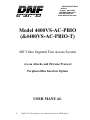
1
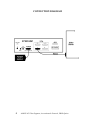
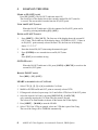
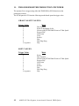
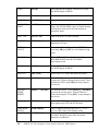
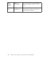
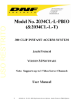
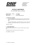
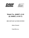
12843 Foothill Blvd., Suite D Sylmar, CA 91342 818 898 3380 voice 818 898 3360 fax www.dnfcontrols.com Model 4400VS-AC-PBIO (&4400VS-AC-PBIO-T) 400 Video Segment Fast Access System Accom Attache and 2Xtreme Protocol Peripheral Bus Interface Option USER MANUAL 1 4400VS-AC Video Segment, Accom Attache Protocol, PBIO Option Table of Contents SECTION CONTENTS PAGE 1. REVISION HISTORY ………………………………. 3 2. SYSTEM DESCRIPTION.................................…….. 3 Getting Started . . . 3. SYSTEM INSTALLATION..................................….. 4 4. SETUP MENU......................................................……. 6 5. LEARN ON THE ST300......................................……. 8 6. LEARN ON THE PRODUCTION SWITCHER…… 9 7. RECALL ON THE ST300...................................……. 9 8. RECALL ON THE PRODUCTION SWITCHER….. 9 9. VIEW CONTENTS OF CUE POINTS…........……... 9 10. PLAY A SEGMENT.............................................…… 9 11. TRIGGERS……………………………………………. 10 Advanced Features . . . 12. TRANSFERRING CUELISTS............................…… 11 Reference . . . 13. FUNCTION TABLE.............................................…… 13 14. SPECIFICATIONS...............................................…… 16 15. KEY LAYOUT ………………………………………. 17 16. DNF CONTROLS LIMITED WARRANTY ………. 18 Manual Version .................................................. 2.4 112503 Document No ...............4400VS-AC-PBIO_User_Manual.doc 2 4400VS-AC Video Segment, Accom Attache Protocol, PBIO Option 1. 2. REVISION HISTORY 101003 Rev. 2.3 Company header information revised. 112503 Rev. 2.4 Updated Transmit Cue List Function and Receive Cue List Function description. Added DNF Controls Limited Warranty. DESCRIPTION NOW, production switchers can load & play video segments on Accom Attache and 2Xtreme. Use the EMEM or SNAPSHOT Learn & Recall functions of the production switcher to load and play a video segment from a Recall or timeline. Use the Run and Trigger functions of the production switcher to Play, Stop or Recue the video segment. The PERIPHERAL BUS INTERFACE Option for the ST300 VTR Controller is special software in the ST300. With this Option, the ST300 has 4 Peripheral Device Addresses, one for each VTR that it controls. This allows the production switcher to control any and all VTRs connected to the ST300. Upon receipt of the Learn command from the production switcher, the ST300 saves the IN and OUT points for the currently defined video segments, the VTRs they are loaded on and the current GANG mode into the appropriate Cue Point. When the Recall command is received, the ST300 loads the learned IN & OUT onto the learned VTRs, cues the VTR to the learned IN time, then restores the learned GANG mode. Learn & Recall may also be done directly from the ST300 without the production switcher. The Trigger function on the production switcher puts the selected VTRs in to Play, Stop, Recue or other available modes. The SEGMENT PLAYBACK option for the ST300 VTR Controller in combination with a DDR or VTR provides a Quick and Easy way to access and play up to 400 video segments. Each ST300 Cue Point consists of an IN point and an OUT point. IN/OUT points can be manually entered or marked with the current “tape” time from the Video Server. All Cue Points are retained when power is off. DEFINITIONS Throughout this document, VTR, DDR, VDR & Video Server will be referred to collectively as “Video Server”. The ST300-S/SM as the ST300. Words surrounded by brackets, for example, [ENTER], are keys on the ST300. [XXX] + [XXX] means hold the two keys down simultaneously. 3 4400VS-AC Video Segment, Accom Attache Protocol, PBIO Option Getting Started . . . 3. SYSTEM INSTALLATION ST300-S/SM, VTR/DDR CONTROLLER 1. Plug one end of a 9 conductor, RS422 serial cable into the VTR 1 (2, 3 or 4) connector on the rear of the ST300. Plug the other end of the cable into the REMOTE connector on the Video Server. 2. Connect the +5, +12, -12 VDC POWER SUPPLY into the POWER connector on the rear of the ST300. Plug the Power Supply into an outlet, 90 VAC to 240 VAC. 3. Check SETUP MENU prior to using the ST300 to confirm proper Record mode and other User settable modes. 4. Select REMOTE mode on the Video Server 's front panel. PRODUCTION SWITCHER 1. Plug one end of a 9 conductor, RS422 serial cable into the “AUX” connector on the rear of the ST300. Connect the other end of the cable to the Peripheral Bus Connector on the production switcher. (Communication Format- 38.4K, N, 8,1) 2. To select a Production Switcher type (default = Grass Valley Group). a. Press [MENU] and turn the wheel until “SWITCHER” is displayed. b. Press Softkey to toggle between Sony and Grass Valley Group types. c. Press [ESC] at anytime to exit MENU mode. 3. 4. The ST300 has 4 Peripheral Device Addresses, one for each VTR that it controls. To set the Device Address for each VTR: Press [MENU] and turn the wheel until “Peripheral Address” is displayed. 5. Press VTR [1], VTR[2], VTR[3] or VTR[4] to select a VTR. 6. Assign a Peripheral Device Address for that VTR, from 0 to 23, by entering the desired address using the numeric keypad. To turn off the address, press [DEL]. Any address >23 turns off the address. 7. Select the next VTR and assign a Peripheral Device Address for it. Each VTR should have its own unique address. 8. When done, press [ESC] to exit the MENU. 9. Configure the production switcher: Enable the Peripheral Bus. Enable the Peripheral Device Addresses assigned to the ST300. Enable the appropriate Learn/Recall levels. Enable the Timeline or Recall Trigger function. Installation is complete. 4 4400VS-AC Video Segment, Accom Attache Protocol, PBIO Option CONNECTION DIAGRAM 5 4400VS-AC Video Segment, Accom Attache Protocol, PBIO Option LCD DISPLAY During normal operation, the top row of the display shows the selected time mode and current time location of the VTR. For example: TM 01:12:09:23 Time Modes - TM= Tape Timer TC= LTC VT= VITC The currently selected SLO-MO speed is displayed on the far right side of the top row. The bottom row of the display shows the current Cue Point number and its contents. 4. SETUP MENU Press [MENU]. The MENU indicator will turn on. Turn the Wheel to select item to change. Press [MENU] OR use the Softkeys to change the desired mode for that option. Turn the Wheel at anytime to select another item. Press [ESC] at anytime to exit SETUP MENU. The [MENU] indicator will turn off. MENU MODES: RECORD (Turning Wheel clockwise) Press [MENU] to select the desired record mode: Lockout, Assemble, Crash (Full) or Insert. Only in INSERT mode: Press the associated Softkey, located below the display, to toggle Video(V), Audio1(A1), Audio2(A2), Audio3(A3), Audio4(A4) on/off. WIND MODE Press Softkey to select: HOLD (fast wind is maintained only while key is depressed) OR LATCH (fast wind is initiated and maintained with momentary key press) Select fast wind speed (3.9 to 23.7) by pressing Softkey below SPD. SLOMO ST300 display shows: SLOMO with: TBAR WHEEL Speed Prset Press Softkey [TBAR] (or [WHEEL]) to toggle between them. NOTE - The T-BAR has a fixed speed range of 0 Æ +200 with a detent at +100 % play speed. For Wheel only: Press Softkey [SPEED] to select SLOMO speed ranges: Press Softkey to select: 0 Æ +200 OR -100 Æ +200. Press Softkey [BACK] to return to SLOMO MENU. Press [ESC] to exit OR turn the Wheel to select another item. 6 4400VS-AC Video Segment, Accom Attache Protocol, PBIO Option For Wheel only: Press Softkey [PRSET] to select the SLOMO Preset Speed Mode. Press Softkey [UPDATE] When exiting SLOMO mode, the last used speed is saved in the Preset Speed register. Press Softkey [STATIC] The Preset Speed register is NOT updated when exiting SLOMO mode. It is only changed by [SHIFT] + [SLOMO] (PRESET SLOMO). ST300 SETUP ST300 SETUP Clear Cues SetDefault Press Softkey beneath ClearCues to clear all Cue Points to 00:00:00:00. Press Softkey [YES] when asked “Are You Sure?” Press Softkey beneath SetDefault to set ST300 to default settings. Press Softkey [YES] when asked “Are You Sure?” DISPLAY The version number for the currently installed software is SOFTWARE displayed. VERSION DROP FRAME Press Softkey to select DROP FRAME ON or OFF. Used in conjunction with Timecode Generator preset. RECORD Press Softkey to select single button or 2-button record. RECORD = [REC] Only OR [REC] + [PLAY] FREEZE Press Softkey to enable or disable FREEZE at Record Outpoint. Changing mode automatically clears FREEZE point. PBIO ADDRESS 1 through 23 SWITCHER Grass Valley Group or Sony TYPE TRANSMIT Transmits Cuelist to another ST300 or to a PC CUELIST RECEIVE CUELIST 7 Receives Cuelist from another ST300 or a PC 4400VS-AC Video Segment, Accom Attache Protocol, PBIO Option 5. LEARN ON THE ST300 MARK AN IN (OUT) POINT Press [IN] ([OUT]). The IN (OUT) indicator turns ON. The second row of the display shows the currently marked IN (OUT) time for ½ second. The current time is marked into the IN (OUT) point. VIEW THE IN (OUT) POINT When the IN (OUT) indicator is ON, the content of an IN (OUT) point can be viewed by pressing and holding [IN] ([OUT]). ENTER AN IN (OUT) POINT 1. Press [SHIFT] + [IN] ([OUT]). The first row of the display shows the current IN (OUT) time. The second row of the display shows “ENTER IN (OUT)”. If there is no IN (OUT) point currently selected on that VTR, the first row of the display shows “??:??:??:??” 2. Enter the desired IN (OUT) time using the numeric keypad. 3. Press [ENTER] to save entered time as an IN (OUT) time OR Press [ESC] to exit without saving. GOTO IN POINT When the IN (OUT) indicator is ON, press [GOTO] or [RECUE] to search to the current IN (OUT) point DELETE IN/OUT POINT Press [DEL] + [IN] ([OUT]). LEARN A SEGMENT INTO A CUE POINT 1. Select VTR [1], [2], [3] or [4] to establish a Cue Point. 2. MARK or ENTER an IN and OUT point on currently selected VTR. 3. If Gang mode is desired, repeat steps 1 & 2 until all the VTRs have IN & OUT points. 4. Select the desired Cue Point by pressing [NEXT CUE], [LAST CUE] or by manually entering the Cue Point using the numeric keypad. The selected Cue Point number is shown on the bottom line of the display. 5. Press [SHIFT] + [MARK] to start the LEARN. 6. Select VTR. If the VTRs are ganged, select one VTR that is part of the Gang. The rest of the Gang will be LEARNed automatically. 8 4400VS-AC Video Segment, Accom Attache Protocol, PBIO Option 7. Press [MARK] to complete the LEARN OR Press [ESC] to exit without LEARNing. The ST300 will: LEARN (save) the VTR Number (1,2,3,4), the current gang configuration and the current IN/OUT time into the selected Cue Point. 6. LEARN ON THE PRODUCTION SWITCHER 1. Select and enable the Peripheral Device Addresses for the ST300. 2. Do a LEARN to the desired REGISTER. The ST300 will save the VTR number, gang configuration and current IN time into the REGISTER number in the ST300. 7. RECALL ON THE ST300 1. Select the desired Cue Point by pressing [NEXT CUE], [LAST CUE] or by manually entering the Cue Point using the numeric keypad. The selected Cue Point number is shown on the bottom line of the display. 2. Press [GOTO] on the ST300. The IN and OUT of the Cue Point becomes the current IN and OUT points. The ST300 parks the learned VTR’s at the IN point. 8. RECALL ON THE PRODUCTION SWITCHER RECALL the desired REGISTER NUMBER. The ST300 will automatically load the Learned Segment on the Learned VTR, cue the clips to the Learned time and set the Learned GANG mode. 9. VIEW CONTENTS OF CUE POINTS 1. Press and hold [SHIFT] + [NEXT CUE] OR [LAST CUE]. The display shows the current cue number and its contents for the current VTR. 2. Release the keys to exit the view mode. 10. PLAY A SEGMENT 1. Select a video segment by pressing [LAST CUE] or [NEXT CUE]. OR Enter the desired cue number on the numeric keypad. 2. Press [GOTO]. 3. Press and hold [SHIFT], then press and release [PLAY]. 9 4400VS-AC Video Segment, Accom Attache Protocol, PBIO Option 11. TRIGGER FROM THE PRODUCTION SWITCHER The operator fires a trigger using either the TIMELINE or RUN function on the production switcher. The ST300 puts the VTR into the following modes based upon the trigger value: GRASS VALLEY VALUES: Trigger Value 0 1 2 3 4 5 6 7 8 9 or greater Mode Play Segment Recue to beginning of clip Slo-mo using ST300 Wheel Preset or T-Bar Speed Reverse Play Still Frame Loop Record Play Play Ping-Pong Play SONY VALUES: Trigger Value 0 1 2 3 4 5 6 7 8 9 or greater 10 Mode Recue Play Segment Slo-mo using ST300 Wheel Preset or T-Bar Speed Reverse Play Still Frame Loop Record Play Play Ping-Pong Play 4400VS-AC Video Segment, Accom Attache Protocol, PBIO Option ADVANCED FEATURES . . . 12. TRANSFERRING CUELISTS The TRANSMIT CUELIST function allows you to transmit your list of Cue Points to a PC, using the provided utility software on the PC, or to another ST300. Transfer to a PC requires OpSuite 3.0 software, which runs on a Windows-based computer. Contact DNF Controls for more information. TRANSMIT CUELIST FUNCTIONS To Transmit a Cuelist to an ST300: 1. Connect the VTR 4 connector on the rear of the ST300 to the VTR4 connector of the receiving St300 using an RS422 9-pin cable with TX and RX lines crossed (A “turnaround” cable.) 2. Press [MENU]. 3. Scroll the wheel until “Transmit CUE List? YES=Enter, Exit=ESC” is displayed. 4. Press [ENTER] to start transmitting. The Display shows “Waiting to transmit” on the first line. 5. When the Receiver is ready, transfer starts automatically. The Display now shows ”Transmitting cuelist”. 6. After the transfer is over, the display shows “Transfer is over” for one second and then shows “Waiting to transmit” again. 7. Connect another ST300 to transmit the list again OR Press [ESC] twice to exit the MENU mode. 8. To Transmit a Cuelist to a PC: 1. Connect the VTR4 connector on the back of the ST300 to one of the COM ports on the PC using a RS422 to RS232 adapter. 2. Repeat steps 2-8 of the TRANSMIT CUE POINTS to the ST300 section. 11 4400VS-AC Video Segment, Accom Attache Protocol, PBIO Option RECEIVE CUELIST FUNCTION. The RECEIVE CUELIST function allows you to receive your list of Cue Points from a PC or from another ST300. Transfer to a PC requires OpSuite 3.0 software, which runs on a Windows-based computer. Contact DNF Controls for more information. To Receive a Cuelist from an ST300: 1. Connect the VTR4 connector on the back of the ST300 from the VTR4 connector of the transmitting ST300 using RS422 9-pin cable with TX and RX lines crossed. (A “Turnaround” Cable) 2. Press [MENU]. 3. Scroll the wheel until “Receive CUE List? YES=Enter, Exit=ESC” is displayed. 4. Press [ENTER] to start receiving. The Display shows “Waiting to receive” on the first line. 5. When the Transmitter is ready, transfer starts automatically. The Display now shows “Receiving cuelist”. 6. After the transfer is over the display shows “Done-Success! Press any key…” 7. Press any key. The display shows “Receive cuelist?” message. 8. Press [ESC] to exit the MENU mode. To Receive a Cuelist from a PC: 1. Connect the VTR4 connector on the back of the ST300 to one of the COM ports on the PC using RS422 to RS232 adapter 2. Repeat steps 2-8 of the RECEIVE CUE POINTS from the ST300 section. 12 4400VS-AC Video Segment, Accom Attache Protocol, PBIO Option Reference . . . 13. FUNCTION TABLE Function Key Press Description EE On/Off [EE] Toggle EE mode on/off. Status indicator is on when EE is on. ENTER TIME [ENTER TIME] To manually entered timecode numbers into the currently displayed Cue Point. Enter the desired timecode number using the numeric keypad. Press [ENTER] to save your entry OR [ESC] to exit without saving. To enter a GOTO location without altering the contents of the Cue Point, enter the desired timecode number using the numeric keypad. Press [GOTO] to search to the entered time. Press [ESC] to exit without searching. FREEZE ON LAST GOOD VIDEO Active in SLO-MO only. In SLO-MO mode, STILL frame the VTR when the current time code is within 6 frames of the last Record Out point (memorized automatically upon exiting Record mode.) Enable, disable or clear FREEZE point from SETUP MENU. GOTO CUE or ENTERED TIME [GOTO] Search the VTR to the contents of the currently displayed Cue Point. If ENTER TIME is active (LED is on), search the VTR to the entered time. To enter a GOTO location without altering the contents of the Cue Point - Press [ENTER TIME]. Enter the desired timecode number using the numeric keypad. Press [GOTO] to search to the entered time. Press [ESC] to exit without searching. GANG [SHIFT] + [VTR#1] [SHIFT] + [VTR#2] [SHIFT] + [VTR#3] [SHIFT] + [VTR#4] Select VTRs to gang together. The ganged VTRs’ LEDs will turn on. Press [ESC] to exit. GOTO FREEZE POINT [SHIFT] + [GOTO] Search VTR to FREEZE point (last Record Out point). 13 4400VS-AC Video Segment, Accom Attache Protocol, PBIO Option FFWD [FFWD] Press and HOLD to shuttle. Release key to stop. Set WIND Speed in MENU. JOG [JOG] Select JOG mode and enable the Wheel. LAST CUE [LAST CUE] Step to the previous Cue Point Location. MARK CUE POINT [MARK] Save the current time in the currently displayed Cue Point. Per SETUP MENU, the Cue Point Location will advance to the next Cue Point location or remain the same. NEXT CUE [NEXT CUE] Step to the next Cue Point Location. PREROLL [PREROLL] Preroll the VTR to the contents of the currently displayed Cue Point. PREROLL VALUE Enter desired Preroll Value. Press [ENTER] to save entry OR press [ESC] to exit without saving entry. RECORD [REC] Places VTR in the Record mode selected by RECORD MODE in the SETUP MENU. One button record. REWIND [RWD] Press and HOLD to shuttle. Release key to stop. Set WIND Speed in MENU. SHUTTLE [SHUTTLE] Select SHUTTLE mode and enable the Wheel. SLOMO [SLOMO] Press SLOMO to slo-mo the VTR. Turn the Wheel or move the T-Bar to change the play speed. Press SLOMO to STILL frame OR press any transport key to exit. SLO-MO SPEED PRESET [SHIFT] + [SLOMO] For WHEEL ONLY - Press [SHIFT] + [SLOMO] to preset the slo-mo speed. Turn the Wheel to select desired speed. Press [ESC] or any transport key to exit. STOP [STOP] Press once to STILL frame VTR. Press again to put VTR into STOP mode. TIME MODE SELECT LOOP PLAY [TIME MODE] Press to toggle between Timecode (TC), VITC (VT) or Tape Timer (TM) display modes. Video segment plays from first frame of video to last frame, then plays again from first frame. Function is continuous. 14 [LOOP PLAY] 4400VS-AC Video Segment, Accom Attache Protocol, PBIO Option TIME PRESET (Generator Preset) SHIFT] + [TIME MODE] Press to enter Time Preset. Press [ENTER] to load Time Generator OR press [ESC] to exit without saving PING PONG PLAY [SHIFT] + [LOOP PLAY] Plays to the end of the segment, then plays backward to the first frame of video, then plays forward. Function is continuous. 15 4400VS-AC Video Segment, Accom Attache Protocol, PBIO Option 14. SPECIFICATIONS Power: Size: Weight: Rear Panel Connectors: Display: Jog/Shuttle Wheel: Optional “T”-bar: 90 VAC to 265 VAC adapter supplied with IEC connector (L” x W” x H”) 12” x 6” x 1.5” (front) 3.0” (rear) 4 lbs. VTR1, VTR2, VTR3, VTR4 (All DB9F) GPI (DBF15F) Power (DB9M) Aux (DB9F) Easy to read 2 line, back-lit LCD display (User adjustable contrast) With mechanical detents Slo-mo 0-200% of Play Speed RS422 Serial Connector 9 Pin D Type, Female (DB9F) Pin # 1 2 3 4 5 Frame Ground Receive A Í Transmit B Î Transmit Common Spare 6 7 8 9 Receive Common Receive B Í Transmit A Î Frame Ground Power Connector 9 Pin D Type, Male (DB9M) Pin # 1 2 3 4 5 +5v DC +5v DC Ground +12 VDC –12 VDC 6 7 8 9 +5 VDC Ground Ground Ground GPI IN/OUT Connector 15 Pin D type, Female (DB15F) Pin # 16 1 2 3 4 5 GPI 1 Out GPI 2 Out GPI 3 Out GPI 4 Out GPI 5 Out 6 7 8 9 10 GPI 6 Out GPI 7 Out Ground GPI 1 In GPI 2 In 11 12 13 14 15 GPI 3 In GPI 4 In GPI 5 In GPI 6 In GPI 7 In 4400VS-AC Video Segment, Accom Attache Protocol, PBIO Option 15. KEY LAYOUT 17 4400VS-AC Video Segment, Accom Attache Protocol, PBIO Option 16. DNF CONTROLS LIMITED WARRANTY DNF Controls warrants its product to be free from defects in material and workmanship for a period of one (1) year from the date of sale to the original purchaser from DNF Controls. In order to enforce the rights under this warranty, the customer must first contact DNF’s Customer Support Department to afford the opportunity of identifying and fixing the problem without sending the unit in for repair. If DNF’s Customer Support Department cannot fix the problem, the customer will be issued a Returned Merchandise Authorization number (RMA). The customer will then ship the defective product prepaid to DNF Controls with the RMA number clearly indicated on the customer’s shipping document. The merchandise is to be shipped to: DNF Controls 12843 Foothill Blvd., Suite D Sylmar, CA 91342 USA Failure to obtain a proper RMA number prior to returning the product may result in the return not being accepted, or in a charge for the required repair. DNF Controls, at its option, will repair or replace the defective unit. DNF Controls will return the unit prepaid to the customer. The method of shipment is at the discretion of DNF Controls, principally UPS Ground for shipments within the United States of America. Shipments to international customers will be sent via air. Should a customer require the product to be returned in a more expeditious manner, the return shipment will be billed to their freight account. This warranty will be considered null and void if accident, misuse, abuse, improper line voltage, fire, water, lightning or other acts of God damaged the product. All repair parts are to be supplied by DNF Controls, either directly or through its authorized dealer network. Similarly, any repair work not performed by either DNF Controls or its authorized dealer may void the warranty. After the warranty period has expired, DNF Controls offers repair services at prices listed in the DNF Controls Price List. DNF Controls reserves the right to refuse repair of any unit outside the warranty period that is deemed non-repairable. DNF Controls shall not be liable for direct, indirect, incidental, consequential or other types of damage resulting from the use of the product. ### 18 4400VS-AC Video Segment, Accom Attache Protocol, PBIO Option