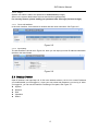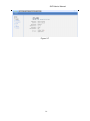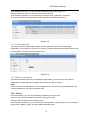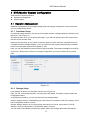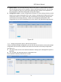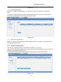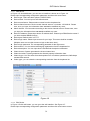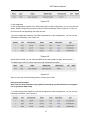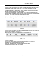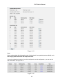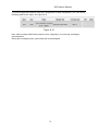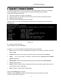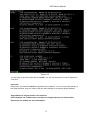
1
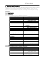
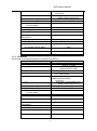
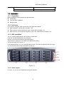
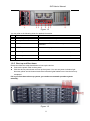
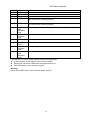
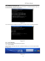
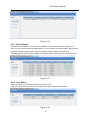
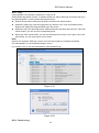
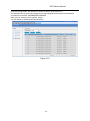
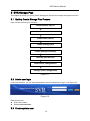
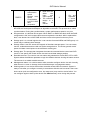
Storage Video Recorder User’s Manual SVR User’s Manual Table of Contents 1 FEATURES AND FUNCTIONS........................................................................... 8 1.1 Specification ........................................................................................................................................... 8 1.1.1 SVR3016H ......................................................................................................................................... 8 1.1.2 SVR3016G ......................................................................................................................................... 8 1.1.3 SVR3016L .......................................................................................................................................... 9 1.2 Installation ............................................................................................................................................. 10 1.2.1 Preparation ...................................................................................................................................... 10 1.2.2 Set Device ........................................................................................................................................ 10 1.2.3 HDD Installation .............................................................................................................................. 10 1.2.4 Cable Layout.................................................................................................................................... 10 1.2.5 Boot up and Shut down .................................................................................................................. 11 2 SYSTEM OPERATION ..................................................................................... 13 2.1 Preparation Work ................................................................................................................................. 13 2.2 Network Setup...................................................................................................................................... 13 2.2.1 Set Controller IP Address .............................................................................................................. 13 2.2.2 Network Connection Test .............................................................................................................. 14 2.2.3 Set IP Address ................................................................................................................................ 14 2.3 3 Boot up Device ..................................................................................................................................... 15 WEB CONFIGURATION ................................................................................... 17 3.1 Web Login ............................................................................................................................................. 17 3.2 System Management .......................................................................................................................... 17 3.2.1 Information ....................................................................................................................................... 17 3.2.2 Parameter ........................................................................................................................................ 18 3.2.3 Organization .................................................................................................................................... 18 2 SVR User’s Manual 3.2.4 Group ................................................................................................................................................ 19 3.2.5 User................................................................................................................................................... 20 3.2.6 Upgrade ............................................................................................................................................ 22 3.2.7 Shut down System .......................................................................................................................... 22 3.3 Network Management ......................................................................................................................... 23 3.3.1 Network Configuration .................................................................................................................... 23 3.3.2 Router Configuration ...................................................................................................................... 25 3.4 Disk Management ................................................................................................................................ 26 3.4.1 Disk Information .............................................................................................................................. 26 3.4.2 RAID Configuration ......................................................................................................................... 29 3.4.3 Storage Pool Configuration ........................................................................................................... 32 4 SVR MONITOR SYSTEM CONFIGURATION .................................................. 35 4.1 Operation Management ...................................................................................................................... 35 4.1.1 Parameter Setup ............................................................................................................................. 35 4.1.2 Storage Setup.................................................................................................................................. 35 4.1.3 Device Configuration ...................................................................................................................... 37 4.1.4 Storage Plan .................................................................................................................................... 39 4.1.5 Alarm Configuration ........................................................................................................................ 41 4.1.6 Configuration Management ........................................................................................................... 44 4.2 System Status ...................................................................................................................................... 45 4.2.1 Service Status ................................................................................................................................. 45 4.2.2 Device Status .................................................................................................................................. 46 4.2.3 Record Status .................................................................................................................................. 47 4.2.4 User Status ...................................................................................................................................... 47 4.2.5 Log .................................................................................................................................................... 48 4.2.6 Service Log ...................................................................................................................................... 48 5 SVR STORAGE PLAN ...................................................................................... 50 5.1 Quickly Create Storage Plan Process .............................................................................................. 50 5.2 Admin user login .................................................................................................................................. 50 3 SVR User’s Manual 5.3 Create system user ............................................................................................................................. 50 5.4 RAID device configuration .................................................................................................................. 51 5.5 Storage pool configuration ................................................................................................................. 53 5.6 Storage Folder Configuration............................................................................................................. 54 5.7 Storage Parameter Configuration ..................................................................................................... 54 5.8 Device Configuration ........................................................................................................................... 55 5.9 Storage Plan Configuration ................................................................................................................ 55 5.10 Alarm Plan Configuration.................................................................................................................... 56 5.11 Enable Storage Service ...................................................................................................................... 57 6 ESS3015A ........................................................................................................ 58 6.1 ESS3015A and SVR ........................................................................................................................... 58 6.1.1 Disk Management ........................................................................................................................... 58 6.1.2 RAID Setup ...................................................................................................................................... 59 6.1.3 Storage Plan Configuration ........................................................................................................... 60 7 APPENDIX A ---TERMS EXPLANATION ......................................................... 62 8 APPENDIX B DISK HOT SWAP OPERATION ................................................. 64 9 APPENDIX C COMMAND OPERATION .......................................................... 71 4 SVR User’s Manual Welcome Thank you for using our Storage Video Recorder (SVR)! This user’s manual is designed to be a reference tool for the installation and operation of your system. 5 SVR User’s Manual How to use SVR User’s Manual If it is your first time to use our SVR, please read Chapter 1 ---Features and Functions After your installation, please refer to the following chapters for setup. Chapter 2 ---System Operation If you want to know the basic system configuration, please read: Chapter 3 ---Web Configuration If you want to know the SVR and front-end device monitor configuration, please read: Chapter 4 ---SVR Monitor System Configuration If you want to quickly use our SVR, please read: Chapter 5 ---SVR Storage Plan If you want to know SVR disk hot swap operation, please read: Appendix B--Disk Hot Swap If you have installed the SVR, but you forgot the password or you want to restore factory default setup, please read: Appendix C- Command Operation Before installation and operation please read the following safeguards and warnings carefully! 6 SVR User’s Manual Important Safeguard and Warnings 1.Electrical Safety All installation and operation should conform to your local electrical safety codes. We assume no liability or responsibility for all the fires or electrical shock caused by improper handling or installation 2.Installation Keep upward. Handle with care. Do not apply power to the unit before completing installation. 3.Qualified Engineers Needed All installation here should be done by the qualified engineers. All the examination and repair should be done by the qualified service engineers. We are not liable for any problems caused by unauthorized modifications or attempted repair. 4.Environment The server shall be installed in a cool, dry place away from direct sunlight, inflammable, explosive substances and etc. 5. About Accessories Be sure to use all the accessories recommended by manufacturer. Contact you local retailer ASAP if something is missing or damaged in your package. 7 SVR User’s Manual 1 Features and Functions This series network storage video recorder (SVR) has installed all necessary software. It works in 1000M network environment (recommended) or 10/100mbps Ethernet. You can use web browser to set network parameter, storage space, and manage device configuration, storage plan and etc. 1.1 Specification 1.1.1 SVR3016H Please refer to the following sheet for SVR3016H specification. Specification SVR3016H Network Port Dual 10/100/1000Mbps Ethernet ports Storage Media 16 SATA Ⅱ HDDs HDD Installation Independent HDD bracket Support HDD hot swap Data Protection Support RAID0/ RAID1/ RAID5 Recommended Channel Amount D1: 128 channels CIF: 256 channels Server Microsoft Windows 2000/XP/NT/Server2003 Linux/Unix Fan Redundant dual ball bearing fan MTBF>100 thousand hours Redundant Configuration Support 2+1 hot swap power Power Consumption 100V~240VAC;50Hz~60Hz; Whole Unit Power Consumption 280W~350W (16 SATA HDDs) Dimension (H*W*D) 133*450*650(mm) Working Temperature 5℃~40℃ Working Humidity 10%~80%(Non condensation) Storage Environment Temperature Storage Environment Humidity Extension Function Altitude Unit Weight (Exclude HDD) -20℃~70℃ 5%~90%(Non condensation) Max 2 ESS3015A,total 46 HDDS -60m~3000m 33Kg Certificate and Security China Compulsory Certificate Unit Fan Support on-line update 1.1.2 SVR3016G Please refer to the following sheet for SVR3016G specification. Specification SVR3016G Network Port Dual 10/100/1000Mbps Ethernet ports Storage Media 16 SATA Ⅱ HDDs HDD Installation Independent HDD bracket Support HDD hot swap Data Protection Support RAID0/ RAID1/ RAID5 Recommended Channel Amount D1: 96 channels CIF: 192 channels Server Microsoft Windows 8 SVR User’s Manual 2000/XP/NT/Server2003 Linux/Unix Redundant dual ball bearing fan MTBF>100 thousand hours Support 2+1 hot swap power 100V~240VAC;50Hz~60Hz; 280W~350W Fan Redundant Configuration Power Consumption Whole Unit Power Consumption (16 SATA HDDs) Dimension (H*W*D) Working Temperature 133*450*650(mm) 5℃~40℃ Working Humidity 10%~80%(Non condensation) Storage Environment Temperature Storage Environment Humidity Extension Function Altitude Unit Weight (Exclude HDD) -20℃~70℃ 5%~90%(Non condensation) Max 2 ESS3015A,total 46 HDDS -60m~3000m 33Kg Certificate and Security China Compulsory Certificate Unit Fan Support on-line update 1.1.3 SVR3016L Please refer to the following sheet for SVR3016L specification. Specification SVR3016L Network Port Dual 10/100/1000Mbps Ethernet ports Storage Media 16 SATA Ⅱ HDDs HDD Installation Independent HDD bracket Support HDD hot swap Data Protection Support RAID0/ RAID1/ RAID5 Recommended Channel Amount D1: 64 channels CIF: 128 channels Server Microsoft Windows 2000/XP/NT/Server2003 Linux/Unix Fan Redundant dual ball bearing fan MTBF>100 thousand hours Redundant Configuration Support 2+1 hot swap power Power Consumption 100V~240VAC;50Hz~60Hz; Whole Unit Power Consumption 280W~350W (16 SATA HDDs) Dimension (H*W*D) 133*450*650(mm) Working Temperature 5℃~40℃ Working Humidity 10%~80%(Non condensation) Storage Environment Temperature Storage Environment Humidity Extension Function Altitude Unit Weight (Exclude HDD) -20℃~70℃ 5%~90%(Non condensation) Max 2 ESS3015A,total 46 HDDS -60m~3000m 33Kg 9 SVR User’s Manual Certificate and Security China Compulsory Certificate Unit Fan Support on-line update 1.2 Installation 1.2.1 Preparation Before installation please prepare the following items: SATA HDD Tools for HDD installation Network cable 1.2.2 Set Device If you want to configure setup, please follow the steps listed below. HDD installation. Please refer to chapter 1.2.3 Connect power cable and network cable. Please refer to chapter 1.2.4. Boot up device and check self-diagnosis is OK or not. Please refer to chapter 1.2.5. 1.2.3 HDD Installation You can use the HDD bracket in the chassis to install HDD. First, pull out HDD bracket from the front panel. Second, remove the bar that fixes the HDD bracket. Third, use four screws to fix one HDD in the HDD bracket firmly. The unit is shown as in Figure 1-1. In the following figure, you can view HDD serial number. The value ranges from left to the right. You can see the 13th to 16th at the bottom of the unit. Figure 1-1 1.2.4 Cable Layout In Figure 1-2, you can see SVR3016H rear panel interface. 10 SVR User’s Manual Figure 1-2 You can refer to the following sheet for detailed information. SN Port Function 1 Power Port Connect to 220V AC 2 Mouse/keyboard port Connect to mouse or keyboard to view device status. 3 USB port Connect to USB device. 4 COM Connect to RS232 COM to go to the command interface. 5 CRT Port Connect to displayer. 6 Ethernet port It is used to transmit data. 1000M Ethernet port. 7 Ethernet port It is used to transmit data. 1000M Ethernet port. 8 Extension Connection Port Connect to the extension disk rack. 1.2.5 Boot up and Shut down Please the follow the steps listed below to boot up the device. Connect the power cable to the system. Click the device power button to boot up the system. You can see power indication light becomes yellow and all channel read-write indication lights flashed once. Now the boot up completed. If it is your first time to boot up system, you need to set network operation system manually. Figure 1-3 11 SVR User’s Manual SN 1 2 3 4 Name Power Alarm Fan Temperature NETb Function If there is error in one of the three alarm sockets, the light becomes red. If there is alarm from the system fan, the light becomes red. If there is alarm from the system temperature, the light becomes red. It is network data channel 2indication light. The yellow light flashes if the network port is working properly 5 NETa It is network data channel 2indication light. The yellow light flashes if the network port is working properly 6 System HDD Indication Light Power Indication Light RESET The blue light flashes when current channel is reading or writing data. System Button After connected the device to the power, click it to boot up the device. 7 8 9 It becomes yellow after you connect device to the power. Click this button to reboot system. 10 HDD Power The yellow light flashes when connect the HDD channel to the power. Indication Light 11 HDD ReadThe blue light flashes when the system is reading or writing the HDD. write Indication Light If you want to turn off unit power, please follow the following steps: In web interface, select option to shut down the system. Please wait until the blue HDD read-write light becomes off. Click PWR button to shut down the system. Warning! Do not click PWR button to shut down the system directly! 12 SVR User’s Manual 2 System Operation 2.1 Preparation Work 10/100Mbps or 1000Mbps Ethernet hub or switcher. Controller of the following configuration: Windows 2000/XP, IE 6.0. Check the real panel cable layout is O.K or not. (Power cable, network card and etc) 2.2 Network Setup SVR default network setup is shown as below: IP: 192.168.0.111. Gateway: 192.168.0.1. Subnet mask:255.255.0.0 User name: admin Password:888888888888(12-digit) To configure device via WEB, you need to set controller panel IP first. 2.2.1 Set Controller IP Address Right click My Network Places, select property. And then right click local connection and then click property, double click internet protocol (TCP/IP). In Internet protocol interface (see Figure 2-1), you can modify IP setup and then click O.K button. Please note controller IP and device IP shall be in the same network segment. Figure 2-1 13 SVR User’s Manual 2.2.2 Network Connection Test In DOS environment, input the command: ping 192.168.0.111. If network connection is right, you can see the following interface. See Figure 2-2. Figure 2-2 If you see an interface is shown as in Figure 2-3, you need to check your network connection. Figure 2-3 2.2.3 Set IP Address Please follow the steps below to set device IP address. 2.2.3.1 Input IP address Open IE browser, input http://192.168.0.111(default IP address) you can see the login interface. See Figure 2-4. Figure 2-4 14 SVR User’s Manual 2.2.3.2 Log in System user name is admin and password is 888888888888(12-digit). Admin is the system administrator account and has the highest priority. For security reasons, please modify your password after first login (At least 12-digit). 2.2.3.3 Go to edit interface In the main interface, from network to network and then click edit button. See Figure 2-5. Figure 2-5 2.2.3.4 Input setup The edit interface is shown as in Figure 2-6 .Here you can input your new IP address information and then click save button. Figure 2-6 2.3 Boot up Device Open IE browser, and input http://10.12.5.9 in the address column (10.12.5.9 is a new IP address you modified after you first logged in.). Input your user name and password, you can log in. After you logged in, you can see an interface consisting of five parts. See Figure 2-7. System Network Disk Operation Status 15 SVR User’s Manual Figure 2-7 16 SVR User’s Manual 3 Web Configuration SVR software operation consists of four parts. Web login System management Network management Disk management The recommended environment: Windows 2000/XP IE v6.0 3.1 Web Login In windows OS, open IE browser and then input system IP address. Click Enter, you can see the following interface. See Figure 3-1. Please input user name and password to login. Figure 3-1 3.2 System Management In this interface, you can see the following seven parts. System information System Parameter Organization Group User Upgrade Shut down 3.2.1 Information After you logged in, you can see system information interface. Or you can click system and then select system information item to go to current interface. See Figure 3-2. Here you can see the following information: System Time Start time Device model Software version Power status CPU temperature Fan speed 17 SVR User’s Manual System displays three fan speeds here including one CPU fan speed. Note: If it is your first time to go to the system, please set system time. When device internal temperature is higher than the threshold value (55 centigrade) or the fan speeds is lower than 1500r/m, system displays corresponding information in red font to alert you. Figure 3-2 3.2.2 Parameter Click parameter button, you can see the following interface. See Figure 3-3. Host name: Current SVR device name. Date: SVR device date. Time: SVR device time. Start auto synchronization setup: Please input server IP and synchronization interval. Start SVR maintenance service: Please check the box and then input auto maintain time and date. System can detect error and fix it through auto maintenance operation. Please note, the time server IP and device IP shall be in the same network segment. After you clicked update now button, system begins synchronizing time with the time server. Figure 3-3 3.2.3 Organization 18 SVR User’s Manual Click organization button, you can see the following interface. See Figure 3-4. System default root name is “root“and it can not be removed. In the following interface you can see there is a second-level organization “overseas” There are two third-level organizations: Sales engineer and technical engineer. Figure 3-4 3.2.3.1 Add Organization If you want to add an organization, please click the add button after the corresponding organization. The interface is shown as in Figure 3-5. Please input the organization name and its note (optional), and then click save button to exit. Figure 3-5 3.2.3.2 Remove Organization Click the delete button after the corresponding organization; you can remove the selected organization. System pops up a dialogue box, please click OK to continue. Note: If there is lower-level organization in current organization, or there are devices belonging to the current organization, the remove operation fails. 3.2.4 Group Click group button, you can see the following interface. See Figure 3-6. Here you can view all operators’ information: name, group type. There are also configuration and delete button. In the following interface, you can see there are two operators: “operator_group” and “overseas”. Please note “operator_group” is system default operator group. 19 SVR User’s Manual Figure 3-6 3.2.4.1 Group Configuration Click configuration button after the corresponding operator group name, you can see the following interface. See Figure 3-7. Here you can select the organization and view the device(s) belonging to it. You can set monitor, play, PTZ and alarm right. Note: When you added a new device, system enable all rights by default. Figure 3-7 3.2.4.2 Remove Group In Figure 3-6, click the delete button after corresponding group, you can remove current group. Note: Once there is user belonging to current group, the remove operation fails. 3.2.5 User Click user button, you can see the following interface. See Figure 3-8. System consists of two-level users: admin level and operator level. Administrator: The admin can read, write or delete all storage data in current system. It can configure the whole system rights. Operator: The operator can use client-end software to begin operation such as user IPC device, search storage recorded files or playback key record. 20 SVR User’s Manual Please note password initialization is for administrator only, admin can click it to restore operator factory default password (123456). Figure 3-8 3.2.5.1 Add user Click add button, you can see an interface is shown as in Figure 3-9. Please input user name, password and then confirm password. Please check the corresponding box group name and then click save button, system goes back to account interface if the operation succeeded. Please note: The user name here can only contain character and number. The added user here is operator user. Figure 3-9 3.2.5.2 Edit User password Click edit button of corresponding user, you can see the following interface. See Figure 3-10. Please input new password and confirm, you can modify the user’s password. Please click save button, system goes back to account interface if the operation succeeded. 21 SVR User’s Manual Figure 3-10 3.2.5.3 Remove User In Figure 3-8, click the delete button of the corresponding user. You can remove current account. System deletes the user name and password, and you can not use current account to login any more. 3.2.6 Upgrade From system to upgrade, here you can see a system upgrade interface is shown as in Figure 3-11. Administrator can use this service to upgrade software. Click browser button to select the upgrade file and then you can click upgrade button to begin update. Note: Before you upgrade the system, please go to our official website to download the latest version. Figure 3-11 3.2.7 Shut down System Click shut down system button; you can see the following interface. See Figure 3-12. There are two options for you: shut down /reboot the system. In each interface, you can see these two buttons on the top right corner. It is very convenient for you to shutdown the system or reboot it. 22 SVR User’s Manual Figure 3-12 3.3 Network Management In this interface you can set device network card and router in the LAN. 3.3.1 Network Configuration Click network configuration button, you can view current network card information. See Figure 3-13. Network card name IP address Subnet mask Default gateway Mac address Status You can also view network status, edit network information, binding or remove the binding. System provides default gateway setup function. Figure 3-13 3.3.1.1 Set network card In the above interface, click edit button you can see the following interface. See Figure 3-14. You can modify IP address, subnet mask, default getaway. Please note, in network binding status, bond0 is the exclusive port for the SVR. If you modify the network port information when SVR service has booted up, system needs to reboot to activate current setup. 23 SVR User’s Manual Figure 3-14 3.3.1.2 View status In Figure 3-13, click status button, you can see an interface is shown as in Figure 3-15. Here you can view current network port connection status; data send out status and receive status. Figure 3-15 3.3.1.3 Remove binding. Click remove binding button in Figure 3-13, you can see the interface is shown as in Figure 3-16. These two cards are displayed respectively. The independent network card etho information is the same as previous binding information. If you want to view network card detailed information, please click status button. If you want to configure the network card, please click corresponding edit button. The interface is similar to Figure 3-16. 24 SVR User’s Manual Figure 3-16 3.3.1.4 Default gateway setup In Figure 3-16, you can set default gateway. If you select etho, then the devices in the WAN can access the SVR via the gateway of etho. In Figure 3-16, the device can use the gateway of 10.10.0.1 to access. 3.3.1.5 Network card binding In Figure 3-13, click network card binding button, you can go to the following interface. See Figure 3-17. Please select two network cards first and then input IP address, subnet mask and default gateway. Click OK button you can complete the binding setup. Please note, if current SVR service has booted up, system needs to reboot to activate current setup. Figure 3-17 3.3.2 Router Configuration From network, select router item, you can view current router setup. See Figure 3-18. No. IP address Gateway Network 25 SVR User’s Manual Interface After you configured the following two routers as the network card, the system default router IP address may vary according to the network card IP address. The first router: The default router setup allows SVR to connect to the pc in the segment 10.12.0.0. The second router: The default router setup allows SVR to connect to the all pc in the segment except 10.12.0.0. Figure 3-18 If the network card binding has removed, you can see an interface is shown as Figure 3-19. Here you can view the etho and eth1 router information. Please note, right now the etho network port is connected and eht1 is disconnected, so in the following figure, you can only see the LAN router and WAN router of etho. Figure 3-19 3.4 Disk Management Disk management is to display disk physical information in the system, configure multiple disks into RAID group and then create storage pool in the RAID group. 3.4.1 Disk Information Please click disk button to view disk information. See Figure 3-20. Here you can review the following information. 26 SVR User’s Manual Channel Disk name Disk space Status Group Use status Type Figure 3-20 3.4.1.1 Display disk S.M.A.R.T. Information When disk channel number is blue, it means current channel disk is available. Now you can view disk S.M.A.R.T. information. Click one channel number; you can go to the following S.M.A.R.T.information interface. See figure 3-21. It includes the following items: Channel Read error Boot up Reallocated Seek error Boot up Correct Temperature Rate In the following interface, there are three buttons: return/detail information/initialization. Back: You can click it to go to previous interface. Initialization: it is to initialize the disk. Disk initialization is going to remove all data in current disk. So, do not use it causally unless there is a must. 27 SVR User’s Manual Detail information: You can click it to view more detail information in a new interface. Click return button you can go back to Figure 3-16. Figure 3-21 3.4.1.2 Add hot spare disk In Figure 3-20, click add hot swap disk button, you can see an interface is shown as in Figure 322. Here you can view idle disk list. You can click the select button to select the hot spare disk. Then you can click save button to exit. Please note one device can max have four disks. Figure 3-22 3.4.1.3 Remove hot spare disk In Figure 3-20, click remove hot spare disk button, you can see an interface is shown as in Figure 3-23. Please note all the disks in the list are hot spare disks. You can click the select button and then click save to remove the hot spare disk. The specified disk now becomes idle. 28 SVR User’s Manual Figure 3-23 3.4.2 RAID Configuration Click raid button, you can see an interface is shown as in Figure 3-24. Here you can see the following information: RAID name Type: RAID5, RAID0, RAID1. Status: It is in synchronization or not. If it is in synchronization, system can display current process. Member disk Total space(Unit: G) The disk group status includes: “clean degraded, recovering”,“clean, recycling” and “clean” RAID1 and RAID5 provide data restore function. But the function becomes valid after the synchronization. When RAID device status is Inactive, it can not be used right now. In the following interface, you can see: There is only one Raid5 device, device name is md1. Right now, md1 is in the synchronization process and has completed 0.1%. It consists of three disks: disk2, disk1, disk9. Its total space is 932G. You can refer to the following information for RAID device capacity calculation. RAID5: Please refer to Appendix A for RAID5 definition. The RAID5 capacity is (N-1)× min(capacityN). CapacityN is the total amount of all disks. You can view the value in the Web. RAID1: Please refer to Appendix A for RAID1 definition. The RAID5 capacity is min (capacityN). CapacityN is the total amount of all disks. You can view the value in the Web. RAID0: Please refer to Appendix A for RAID0 definition. The RAID5 capacity is the total amount of all disks. You can view the value in the Web. 29 SVR User’s Manual Note: If RAID device is in synchronization process now, system can display current percentage and speed (MB/S). Usually, please use the device after the synchronization completed. That is to say, do not create storage pool logic volume during the synchronization. Figure 3-24 3.4.2.1 Edit RAID configuration In Figure 3-24 click edit button after specified RAID, you can go to the edit interface. See Figure 3-25. Here administrator can remove one RAID device or and a disk. Please note, you can not add or remove RAID1/ RAID5 unless the RAID1/RAID5 group is damaged. Figure 3-25 RAID5 Remove disk: System max supports one disk. All data are safe after remove. After removed the disk, RAID5 device is in degrading status. Please note RAID 5 is invalid once you remove more than one disk. 30 SVR User’s Manual Note: Do not remove the disk casually unless there is a must! Do not remove the disk when RAID5 device is in synchronization process. If you find one RAID5 disk is malfunction, please remove the disk in the interface and then remove it from the chase. Insert disk: This operation also needs to be done after synchronization. Before you add a disk, you first need to remove one disk. Otherwise you cannot add any disk. If you have removed one RAID5 device disk, you can add another one. Then you can see system begins synchronization after the add operation. All data in the device are safe. RAID1 Remove: System max supports one disk. All data are safe after remove. RAID1 device can use properly. Note: Do not remove the disk casually unless there is a must! Do not remove the disk when RAID1 device is in synchronization process. If you find one RAID1 disk is malfunction, please remove the disk in the interface and then remove it from the chase. Insert disk: This operation also needs to be done after synchronization. Before you add a disk, you first need to remove one disk. Otherwise you cannot add any disk. If you have removed one RAID1 device disk, you can add another one. Then you can see system begins synchronization after the add operation. All data in the device are safe. RAID0 You can not remove or add disk. See Figure 3-26. Figure 3-26 3.4.2.2 Add RAID configuration In Figure 3-24, click add button, you can see an interface is shown as below. See Figure 3-27. Here you can select RAID type (RAID0,RAID1,RAID5)Then you can select the RAID device disk. All disks listed below are available to be used. Last, you can click save button to complete the add operation. 31 SVR User’s Manual Figure 3-27 3.4.2.3 Remove RAID configuration The remove operation includes the following three environments. (See Figure 3-24) Current RAID group has not been used: That is to say, there is no storage pool. You can click remove button to delete RAID group directly. System is using current RAID group: That is to say, there is storage pool in current RAID group, but there is no share directory. You need to remove the storage pool first and then remove the RAID group. Otherwise the operation may fail. System is using current RAID group: That is to say, there is storage pool and there is share directory in the pool. You need to remove all directories in the storage pools first and then remove the storage pool. Finally, you can remove RAID group. 3.4.3 Storage Pool Configuration From disk to storage pool item, you can see an interface is shown as in Figure 3-28. Here you can view the storage pool information. Storage pool name Member device Total space Used space Please note, if current storage pool is damaged. You can see the corresponding prompt saying current storage pool has been damaged. Now the total space and used space both are shown as 0. 32 SVR User’s Manual Figure 3-28 3.4.3.1 Add storage pool The storage pool device includes RAID device (RAID5 / RAID1 / RAID0), single disk (such as disk1), disk combination (such as disk 2,disk3). Usually we recommend RAD1 and RAID5. You can select the device and then click save button to exit. See Figure 3-29. Note: We recommend to use RAID1/RAID5. Figure 3-29 3.4.3.2 Edit storage pool In Figure 3-28, click edit button, you can see an interface is shown as in Figure 3-30. Here you can view all share folder information in the storage pool. If the storage directory does not exist or it has not been successfully mounted. You can view the use status is shown as “not available” and there is a corresponding remove button for you to remove current device. 33 SVR User’s Manual Figure 3-30 3.4.3.3 Remove storage pool The remove operation includes the following two environments. See Figure 3-28. There is no storage configuration: You can click remove button directly. There is storage configuration: You need to remove the storage configuration first and then you can remove the storage pool. 34 SVR User’s Manual 4 SVR Monitor System Configuration SVR extension function includes: Operation management System status 4.1 Operation Management Operation management is to manage storage plan and storage configuration, at the same time you can configure the device. 4.1.1 Parameter Setup In parameter setup interface, you can set record pack duration, storage capacity information and log service. See Figure 4-1. The pack duration is for you to specify file length. If you set five minutes here, then all recorded files are of five minutes video. Reserved volume setup is very useful in case the system is down when the recorded files have occupied the whole storage capacity. If you set 10G here, then system automatically overwrites previous records when system free capacity is 10G. Here you can also enable log service and set log saved path. The setup here applies to the SVR service log. Please note if there is no storage configuration, you can not select the log saved path. Figure 4-1 4.1.2 Storage Setup Click storage set button, the interface is shown as in Figure 4-2. Here you can view storage directory, volume group, total space, free space, system status and configuration status. In the following interface, you can see there are two storage setups. Setup1: storage direcoty is 99,RAID5 group, total volume is 0 and free volume is 0.system now is bad. Configuration status is normal. Setup2: storage directory is ew, poola group, total volume is 132.93, free volume is 132.90. System is now running properly. Configuration status is normal. You can refer to the following contents for system status and configuration status information. 35 SVR User’s Manual System status: It is the storage directory status in the system. If system status is normal then the storage directory can run properly. If there is abnormal phenomenon, then the data from he storage plan may loss, it has close relationship wit the proper record operation of the storage plan, it affect the storage data security and integrity. Configuration status: It means configuration information of current storage directory can be saved ion the system configuration file or note. If there is configuration file being saved, then configuration status is use, which means the recorded data of corresponding storage plan can be saved in the storage directory. If there is no corresponding information in the configuration file, then the recorded data can not be saved in the specified storage directory. Figure 4-2 4.1.2.1 Storage configuration status in abnormal environment If there is abnormal storage configuration, you can click the remove button to remove the storage configuration. But the remove operation will delete all record data in the storage configuration. See Figure 4-3. For system status, there are two abnormal statuses: Storage pool is damaged/File system is abnormal. For use status, the abnormal status is configuration error. Do not operate it casually unless there is a must! 36 SVR User’s Manual Figure 4-3 4.1.2.2 Add storage directory In Figure 4-1, please click add button. You can see an interface is shown as in Figure 4-4. Note: In case there is abnormal device status, system usually reserves 5G from the total space for record space management. Please click save button to exit. Figure 4-4 4.1.2.3 Remove storage directory Before you remove storage directory, please disable SVR service (Figure 4-15) and then click remove button (Figure 4-4). 4.1.3 Device Configuration Click device configuration button, the interface is shown as in Figure 4-5. Here you can view device number, device name, device type, device channel amount, device IP address and its belonging organization. You can use choose all/choose none button to quickly select all or cancel all devices. Figure 4-5 37 SVR User’s Manual 4.1.3.1 Add device In Figure 4-5, click add button, you can see an interface is shown as in Figure 4-6. Please input corresponding configuration parameter and then click save button. Device type: There are three options: DVR/IPC/NVS. Device name: You can input a self-defined name. Device manufacture: Please select a name from the dropdown list. Device channel amount: Device record channel amount. It includes: 1/2/3/4/8/16. Please note, once you input, the information here can not be modified any more. Alarm channel: You can select according to the device channel amount. Please note, once you input, the information here can not be modified any more. Device IP address: Please input device IP address here. Please input DDNS device name if you have enabled DDNS function. Device port: Default value is 37777. Device login name: Please input a name for your login. This name shall be reusable (Multiple users can use this account to login at the same time.). Device login password: The corresponding password for the login name. Device owner: You can select its belonging organization from the dropdown list. Device description: You can input device self-defined description information. Channel name: System generates the channel name here. Channel number: System generates the channel property information here. Channel type: You can select from the dropdown list. It includes: speed dome,/Half-shape camera/fixed camera. Codec type: you can select the corresponding resolution from the dropdown list. Figure 4-6 4.1.3.2 Edit Device In Figure 4-5 click edit button, you can go to the edit interface. See Figure 4-7. Please input corresponding configuration parameter and then click save button to save. 38 SVR User’s Manual You can refer to chapter 4.1.3.1 for more information. Please note channel name and channel number information here is generated automatically. Figure 4-7 4.1.3.3 Remove Device In Figure 4-5 click remove button, you can delete the mounted front-end device. 4.1.4 Storage Plan Click storage plan button, you can go to the following interface. See Figure 4-8. Here you can view the storage plan information such as serial number, storage plan name, camera, storage plan name (Content), storage position, status. You can use choose all button to check all plans here. You can use change status button to modify several plans at the same time. In the following interface, you can see: The first storage plan name is “100101301_2009072116550” The device is DVR_10.12.8.71. It is schedule record and the record becomes valid in 00:00:00 to 23:59:00. The recorded file is in storage in folder 66 and current plan has been enabled. 39 SVR User’s Manual Figure 4-8 4.1.4.1 Add storage plan In Figure 4-8, click add button, you can go to an interface shown as in Figure 4-9. System can backup the corresponding device channel data of enabled storage plan in specified storage directory. Please input configuration parameter, then click save button, you can add a storage plan. Camera: Select the channel from the front-end device. There are four buttons: add one single device channel(“->”), add several device channel (“=>”), remove single device channel(“<-”), remove several device channel(“<=”). Plan name: System auto creates the plan name. It consists of device number+channel number_ creation time. Storage position: Please select a created storage position. Store strategy: Here you can select the record type. It includes: full day record and schedule record. 40 SVR User’s Manual Status: Here you can enable or disable storage plan. Note: Memorize corresponding event. Figure 4-9 4.1.4.2 Edit storage plan In Figure 4-8, click edit button, you can go to the following interface. See Figure 4-10. Please note, you just can edit plan name and status only. Figure 4-10 4.1.4.3 Remove storage plan In Figure 4-7, click remove button directly, you can remove one storage plan. 4.1.5 Alarm Configuration Click alarm configuration button, you can see an interface is shown as in Figure 4-11. 41 SVR User’s Manual Here you can view the following item: Serial number:1. Alarm device:dvr_10.12.5.36 Device IP address:10.12.5.36 Alarm name: Alarm test Alarm channel:100100301 Alarm type: Video loss Storage position: The folder share Status: Current alarm policy has been enabled. You can click it to disable current policy. You can use choose all button to check all alarm plans here. You can use change status button to modify several alarm plans at the same time. Figure 4-11 4.1.5.1 Add alarm plan In Figure 4-11, click add button, you can see an interface is shown as below. See Figure 4-12. Alarm device: You can select a mounted front-end device. If there is external alarm channel, the alarm device name is shown as Device name+device ID+ACH+alarm channel. Alarm name: You can input self-defined information here. Alarm type: There are four options: video loss/camera masking/motion detection/external alarm. Please note, according to the device configuration information, if you have selected one alarm channel as alarm device, then you can only select external alarm here. If you have selected ordinary record channel as alarm device, then you can only select: video loss/camera masking/motion detection. Record device: You can view all configured device on the left side column. You can select the button “->” or “->>” to select device. And you can use “<-” or “<<-” to remove device. You can also move you mouse to the device and then you can see import option to add the device. Record time: You can input record duration here. Storage position: You can specify the folder to save the recorded file. Period: You can set the period for the record operation Status: You can click enable button to activate current record plan. 42 SVR User’s Manual Note: You can input self-defined information here. Please note the storage position is for you to specify the path to save recorded file of one channel. For one channel, you can specify one path for both the storage plan and the alarm configuration. Please input corresponding parameter and then click save button to add an alarm plan. Figure 4-12 4.1.5.2 Edit alarm plan In Figure 4-11, click edit button, you can see an interface is shown as below. See Figure 4-13. Please note you can just modify alarm name, record time, period and status. 43 SVR User’s Manual Figure 4-13 4.1.5.3 Remove alarm plan In Figure 4-11, click remove button, you can delete the alarm plan. 4.1.6 Configuration Management Click configuration management button, you can go to the following interface. See Figure 4-14. In the following interface, you can import or export SVR system file. When current SVR storage is abnormal, you need to remove the storage configuration and storage pool, and configure system. You can use this function. Before remove configuration, please click export button, you can export current user configuration and device configuration. After you configured the storage pool and storage configuration, please import the configuration files again. Then you can get the user configuration and device configuration as before. 44 SVR User’s Manual Figure 4-14 4.2 System Status System status includes the following items: SVR service status, device management, record status, record status, and user status and log information. 4.2.1 Service Status Click service status button, the interface is shown as in Figure 4-15. Here you can view SVR configuration status, time synchronization server status and network protocol server status. The SVF configuration service includes database status, SVR service status and maintenance service status. You can click set button to set corresponding information. Database status SVR provides database service configuration function. It includes data service and database synchronization. Boot up database service: In Figure 4-15 click start button and then click set button. Disable database service: In Figure 4-15 click stop button and then click set button. Reboot database service: In Figure 4-15 click restart button and then click set button. SVR service status SVR service status includes: configuration service, device management service, transmission service and storage service. When it is in enabled status, it means current SVR service is available. If the SVR service is disabled and maintenance service is enabled, system can auto enable SVR service. Enable SVR service: In Figure 4-15 click start button and then click set button. Disable SVR service: In Figure 4-15 click stop button and then click set button. Reboot SVR service: In Figure 4-15 click restart button and then click set button. Maintenance service status SVR provides maintenance service. Enable maintenance service: In Figure 4-15 click start button and then click set button. Disable maintenance service: In Figure 4-15 click stop button and then click set button. Reboot maintenance service: In Figure 4-15 click restart button and then click set button. 45 SVR User’s Manual Time synchronization server SVR provides the time synchronization function. Use this function; you can synchronize the other device to the SVR. Enable time synchronization service: In Figure 4-15 click start button and then click set button. Disable time synchronization service: In click Figure 4-15 click stop button and then click set button. Reboot time synchronization service: In Figure 4-15 click restart button and then click set button. Network protocol server SVR communicates with other front-end device via network protocol. The network protocol service is very important. If its status is abnormal, you need to reboot the network protocol service. Enable network protocol server service: In Figure 4-15 click start button and then click set button. Disable network protocol server service: In click Figure 4-15 click stop button and then click set button. Reboot network protocol server service: In Figure 4-15 click restart button and then click set button. Figure 4-15 4.2.2 Device Status Click device status, you can see an interface is shown as in Figure 4-16. Here you can view all mounted devices. Here you can view device serial number, device name, device type, device channel amount, device IP address, device position and status. 46 SVR User’s Manual Figure 4-16 4.2.3 Record Status Click record status button, you can see an interface is shown as in below. See Figure 4-17. Here you can view all valid record plan status. You can view device serial number, device name, device IP address, channel name, channel number, storage position and start time. If the storage plan has not been enabled, the storage position and start time are shown as NA. Figure 4-17 4.2.4 User Status Click user status, the interface is shown as in Figure 4-18. Here you can view all user account. It includes user name, alias, type and status. Figure 4-18 47 SVR User’s Manual 4.2.5 Log Click log button, the interface is shown as in Figure 4-19. SVR provides log search function. It supports search all, search latest log and search the log in the specified period. It also provides log export function. Search all logs: Select search all log button and then click search button. Search the latest logs: Input the log amount you want to view. Then click search button. System can display the latest specified log in the screen. Search the log in the specified period: Please select the start time and end time. Then click search button, you can view the corresponding logs. Export log: Click export button, you can see a dialogue box shown as in Figure 4-20. Click save button, you can save logs in your local pc. Note: System max supports 1000 logs. Once it is full, the old log will be overwritten by default. For administrator, he can download all logs in the pc For ordinary user, he can only download his own operation logs. Figure 4-19 Figure 4-20 4.2.6 Service Log 48 SVR User’s Manual Click service log button, the interface is shown as below. See Figure 4-21. The interface here is to provide system service log management function for the operators. It includes five services: CMS/DMS/MTS/SS/RMS. Here you can view log name, log time, length. You can delete or download the specified logs. Figure 4-21 49 SVR User’s Manual 5 SVR Storage Plan This chapter is to help you quickly create storage plan and provide storage management service. 5.1 Quickly Create Storage Plan Process Here is a flow chart for your reference. Administrator logs in Create a user Create RAID device Create storage pool Create Storage Directory Boot up SVR Service Add Device Configuration Storage Plan Configuration Figure 5-1 5.2 Admin user login In the login interface, you can input administrator name and password to log in. See Figure 5-2. Figure 5-2 Default account is: User name: admin. Password:88888888888. 5.3 Create system user 50 SVR User’s Manual From the system management, select user management. See Figure 5-3. Figure 5-3 In user interface click add button, you can see an interface is shown as in Figure 5-4. Figure 5-4 Create system user Here you can create a user such as user1. See Figure 5-5. Figure 5-5 5.4 RAID device configuration Here we take RAID5 as an example. From disk management, select RAID configuration. See Figure 5-6. 51 SVR User’s Manual Figure 5-6 Now you can see an interface is shown as in Figure 5-7. Please click add button to go on. Figure 5-7 You can see an interface is shown as in Figure 5-8. Here you can select RAID5 device (at least three disks) 52 SVR User’s Manual Figure 5-8 Note Before using devices here, please enable RAID5 device synchronization process. 5.5 Storage pool configuration From disk management, select storage pool configuration. See Figure 5-9. Figure 5-9 Now you can see an interface is shown as n Figure 5-10. 53 SVR User’s Manual Figure 5-10 Click add button. Now you can configure storage pool. See Figure 5-11. Here you can see raid5 device disk15 constitutes storage pool1. Figure 5-11 5.6 Storage Folder Configuration From operation item, select storage set. Click add button, you can see the following interface. See Figure 5-12. Figure 5-12 5.7 Storage Parameter Configuration Click parameter button, you can set pack time, reserved volume, log path and then enable current function. See Figure 5-13. 54 SVR User’s Manual Figure 5-13 5.8 Device Configuration And then in Figure 5-12, click device set button on the left side and then click add button. The interface is shown as in Figure 5-14. Please input the corresponding information and then click save button to exit. Figure 5-14 5.9 Storage Plan Configuration From operation item, select storage policy button. Then please click add button. You can go to Figure 5-15 to set storage plan. 55 SVR User’s Manual Figure 5-15 5.10 Alarm Plan Configuration From Operation to Alarm policy, and then click add button. You can go to Figure 5-16. Here you can set alarm plan. Figure 5-16 56 SVR User’s Manual 5.11 Enable Storage Service From Status to service status item, the interface is shown as in Figure 5-17. Please enable SVR service and database service. Figure 5-17 57 SVR User’s Manual 6 ESS3015A ESS3015A is disk extension rack. It applies to extend network intelligent storage capacity. 6.1 ESS3015A and SVR Disk rack connects to HBA via miniSAS cable. HBA connects to SVR via PCI or PCI-X slot. You can refer to Figure 6-1. Figure 6-1 One SVR can connect to two HBA and one HBA can connect to two SVR devices. One ESS3015A can install 15 SATA disks. So ESS3015A device can effectively extend SVR capacity. In this chapter, we talk about how to extend SVR capacity. Though ESS3015A (disk rack) is an extensible device, but for SVR device, it just adds some available disks in the system. The Web operation and share application is the same as SVR. Here we merely talk about the difference. 6.1.1 Disk Management From disk management to disk management, you can see an interface is shown as in Figure 6-2. Here you can see there are five buttons. Host and expand 1/2/3/4. It shows current SVR connects to four disk racks. When you go to disk information interface, system just shows host rack information by default. You can click expand rack button to view corresponding information. 58 SVR User’s Manual Figure 6-2 6.1.2 RAID Setup From disk management to RAID setup, you can see an interface is shown as in Figure 6-3. System displays host rack RAID configuration information by default. You can click expand disk rack button to view corresponding information. Please note, though sometimes user interface just shows there is only disk rack1, you can not say there is only one disk rack connects to current SVR. If you have not created RAID device in disk rack 2, system just shows there is one host rack and one expand rack1. 59 SVR User’s Manual Figure 6-3 Add RAID Setup In Figure 6-3, click add button, you can see an interface is shown as in Figure 6-4. Here you can select RAID type (RAID0, RAID1, and RAID5), disk rack number (host, expand1/2/3/4) and then select disks to create a RAID device. In this interface you can just see all the available disks, those used or malfunction disks will not be displayed,. Click save button after you complete adding RAID device operation. Figure 6-4 6.1.3 Storage Plan Configuration From disk management to storage pool configuration, you can see the storage pool information. See Figure 6-5. 60 SVR User’s Manual System displays host storage pool information by default. The Host button is blue. You can click Expand1 button to view the storage pool information in the rack 1. Please note, the following figure does not mean there is only one Expand in current SVR. For example, current SVR connected to two rack (Expand 1 and Expand 2), but you only created storage pool in the Host and Expand 1. Then system does not display Expand 2 because there is no storage pool in it. Figure 6-5 61 SVR User’s Manual 7 Appendix A ---Terms Explanation Here are some terms explanations in this user’s manual. SVR: It is the abbreviation for Storage video recorder. It adopts large capacity HDD, RAID technology to store large data and can guarantee high safety. DVR: It is the abbreviation for digital video recorder. SATA:It is the abbreviation for serial ATA. In current released Serial ATA 2.0, data transmission speed can reach 300MB/second. RAID: It is the abbreviation for redundant array of independent disks. It is to combine several independent HDDs (physical HDD) to form a HDD group (logic HDD) to provide more storage capacity and data redundancy. Now it consists of seven levels, ranging from RAID0 to RAID6.Besided, it has some basic RAID combination groups such as RAID10 (RAID0 and RAID1, RAID 50(RAID 0 and RAID 5). Here is a comparison between RAID 0, RAID 1, RAID 5. In this manual, we call RAID5, RAID 1,RAID0 as RAID5 device, RAID1 device and RAID 0 device respectively. RAID0: RAID0 is so called Striped Disk Array without Fault Tolerance. It represents the highest storage performance in RAID level. RAID0 is to read-write continue data in several HDD. So, system data query will be performed in several HDDs at the same time. RAID1: It is also called Mirror or mirroring. Its aim is to maximally guarantee data safety and restorable. RAID1 is to automatically copy user input data fully to other RAID1 HDDs. RAID 5: RAID5 does not backup the storage data. Instead, it will memorize data and corresponding verification information to HDDs of RAID5. The data and verification information will be backed up in different HDDs respectively. When data in one of the HDDs is damaged, system can use the rest data and corresponding verification information to restore the lost data. RAID Advantage RAID 0 RAID 1 High readwrite efficiency. No verification to occupy CPU resources. Easy to design, use and configure Theoretically , it has double speed. 100% data redundancy function. Easy to design, use and configure. Disadvantage No verification or restore function. No data error tolerance. Not suitable for harsh environment. Min HDD Amount Applied zone 2 Create and edit video Low HDD use efficient. High storage cost. In soft RAID1 mode, performance descends gravely. 62 2 Financing statistics and data base financing system. Need high maintena nce work. SVR User’s Manual High read HDD error will transmission affect the speed. File and input and Medium write applicatio output speed. speed, RAID 5 4 n server, The controller Considerable database design is a low ECC HDD server. little bit data difficult. occupation. Synchronization: After creating RAID 1or RAID5, before using, system needs to read-write the HDD at a fixed speed and adopts an algorithm to calculate. This process is so called synchronization. During the synchronization, system performance speed is very low. Hot spare disk: It is disk set as hot spare. When RAID1 or RAID5 lost disk, while the RAID configuration is OK, the hot spare disk can auto replace the lost disk. After it replaced the disk, it can become one of the RAID and does not have hot spare function any more. Storage pool: it is a virtual logic device. It can consist of several HDDs and RAID group. It is a main way to realized virtual storage. Storage folder: Local PC access the top path of the share storage space. You can create, remove, authenticate and set valid user at the storage device. It includes general record space and alarm record space to save different record types. Storage plan: The storage plan integrates the external connected device record and SVR record. It can specify the record device time and record data storage position. Reusable account: You need to use user name and password to access DVR, IPC or NVS. System allows the different operators to login the different devices b using the same account. The account is so-called reusable account. Management status: It is a device status when controller configure device via web. Actually, when there is no error or damage, device shall be always in management status. Working status: It is a device status when controller access HDD via network. System is ready to use after you configure correctly in accordance with this user’s manual. Some nondevice error (such as configuration error, hot swap error) may result in device failure. You can configure again to boot up the device. But data loss may occur during this process. 63 SVR User’s Manual 8 Appendix B Disk Hot Swap Operation Hot swap operation instruction. When device is in management mode (Please refer to appendix A---Terms Explanation), after dismantle or insert disk, system is still in management mode and no damage to the system and disk. Whether system is in working status (Please refer to the terms explanation), it depends on the administrator operation. Here we talk about how to operate hot swap operation while at the same time guarantee device is always in working status. Note: Only RAID5 and RAID1 can guarantee data safety and support data restore function. So, before your operation, please make sure the disk group to be hot swapped is set to be the RAID1 or RAID5. When RAID device is in working status, RAID1 and RAID5 support hot swap one disk. After hot swap, the working RAID 1 and RAID 5 become degrading level. If you dismantle one more disk, it may result in data loss in the whole group disk! Now system only support hot swap in degraded RAID5/RAID1 group, and then RAID device becomes ready status. Device returns to working status after disk synchronization. Note: please use SVR when RAID is in working status. Hot swap only be operated when RAID is in working status, otherwise it may result in data loss in RAID device! Ready status: It only applies to RAID1/RAID5, e.g these disk groups are in RAID synchronization. When disk group are in ready status, in the web configuration interface, from disk management to RAID configuration, you can see the corresponding RAID group status is “clean,degraded,recovering”. Working status: it only applies to RAID1/RAID5. It is a RAID status after synchronization. When disk group are in ready status, in the web configuration interface, from disk management to RAID configuration, you can see the corresponding RAID group status is “clean,degraded,recovering”. Degraded status: It only applies to RAID1/RAID5. e.g the working RAID disk group status after hot swap a disk. When RAID is in degraded status, in the web configuration interface, from disk management to RAID configuration, you can see the corresponding RAID group status is “clean,degraded”. Operation example The RAID5 and RAID1 have the same hot swap operation steps. Now we take RAID5 as an example. 64 SVR User’s Manual In SVR, there is a RAID5 disk group consists of four disks (dsk1, disk2, disk3, disk4.). All these four disks are in working status. Note: SVR max supports 16 SATA disks. But for performance and safety consideration, we recommend RAID 5 consists of four to six disks, RAID1 consists of two to three disks. Note: Here we just take four disks as an example. When your disk amount is more than 4, the operation is just the same. 1). Disk hot swap example. In web configuration interface, from disk management to disk information, you can see the information before hot swap. See Figure 8-1. Here you can see the following information: In SVR, disk group has four disks. The four disks are: dsk1, disk2, disk3, disk4. These four disks are corresponding to channel 1 to channel 4 respectively. All disks are in running status, which means there is no error. Figure 8-1 2) In web configuration interface, from disk management to RAID configuration, you can see current RAID device status. Before hot swap, please make sure the disk to be hot swapped is in RAID5 (RAID1) and RAID5 (RAID1) is in working status. See Figure 8-2. Figure 8-2 3). Log out disk to be hot swapped. In Figure 8-2, click edit button of the corresponding RAID device. You can see an interface is shown as in Figure 8-3. Here you can see the following information: RAID 5 device md0 total space is 698.66, and it consists of four disks. The RAID status is in working status. (Clean mode). The group consists of four disks: disk1, disk2, disk3, disk4. There is a newly added disk list. Check remove button after disk1 and then click save button. Now you are about to remove disk1. 65 SVR User’s Manual Figure 8-3 4).In web configuration interface, from disk management to disk information, you can see the disk information after hot dismantle: disk1 is in free status. See Figure 8-4. Now there are two options: You can remove the disk1 from the rack. You can insert the disk1 into other RAID5/RAID1 in degraded mode. And then create storage pool and share folder to provide share service. Figure 8-4 5).In web configuration interface, from disk management to RAID configuration, you can see RAID device status. See Figure 8-5. After hot swap disks, RAID5 device from working status to clean, degraded status. Current RAID5 disk group can still work properly. 66 SVR User’s Manual Figure 8-5 6). Hot swap disk In web configuration interface, from disk configuration to disk configuration, you can see the disk status. Disk3 corresponding channel number is channel 3(Please refer to Figure 8-4), now you can remove the corresponding disk from the rack. 7).In web configuration interface, from disk configuration to disk configuration, you can see the RAID status information. See Figure 8-6. Figure 8-6 8).from disk to RAID, you can view the RAID device status after hot swap. See Figure 8-7. The RAID status after hot swap is the same with that before hot swap. Figure 8-7 Now you can refer to the following part for inserting a new disk. Hot insert disk example. Note: The hot insert operation only applies to the disk group that has been hot swapped. It is to guarantee data safety. 1). In web configuration interface, from disk configuration to disk configuration, you can see the following information. See Figure 8-8. 67 SVR User’s Manual Figure 8-8 2). Insert the disk directly to the idle disk channel of SVR and memorize the disk channel name (such as disk1). In this example, we are going to insert the disk1 that just was removed. From disk management to disk information, you can review disk information before hot swap. And then check disk information again after hot swap. Compare the information before and after hot swap. You can see before hot swap, there are three disks: dksk2, disk3, disk4. After hot swap, you can see the there are four disks: disk2, disk3, disk4, disk1. Now you can see the newly inserted disk name is disk1. 3). In web configuration interface, from disk configuration to disk information, you can see the disk information. See Figure 8-9. Figure 8-9 4).In web configuration interface, from disk configuration to RAID configuration, you can see the following RAID device status. See Figure 8-10. Since current disk group md4 is in degraded status, you can add disk now. Figure 8-10 5). Insert hot swap disk. In Figure 8-10, click edit button, you can see an interface is shown as in Figure 8-11. Now please check the add button and then click save Please note, hot swap operation only applies to degrade RAID1/RAID5 RAID begins synchronization again after hot swap. 68 SVR User’s Manual Figure 8-11 Note: Since newly added disk information take “disk volume” as a symbol (such as disk1), so in the step (2) please memorize hot swap disk name. 6).In web configuration interface, from disk configuration to disk configuration, you can see the disk information. See Figure 8-12. Figure 8-12 69 SVR User’s Manual 7) In web configuration interface, from disk configuration to RAID configuration, you can see the following RAID device status. See Figure 8-13. Figure 8-13 Note: after hot swap, RAID5 device status is from “degrading” to “recovering” and begins synchronization. During the hot swap process, system data will not be damaged. 70 SVR User’s Manual 9 Appendix C Command Operation The command operation is very useful in case you forgot administrator password or IP address. This function applies to our all series SVR. Here we take SVR3016H as an example. Please follow the steps listed below: Connect the SVR to the monitor via COM port. Login the system via “dh_admin” account and then go to the Debug command interface. Debug command operation. Login Debug command operation via “dh_admin”. Input user name “dh_admin” and its paaword debug after the corresponding command prompt. See Figure 9-1 Figure 9-1 Debug command operation Input command “help” after “#DEBUG>“ In Figure 9-1, you can see Debug command provides seven commands: help: Here you can view the corresponding information of the Debug command. Command format:help. netshow: Here you can view system current IP address. Command format: netshow netset: It is to reset system IP address. Command format: netset bond IP netmask gateway (Optional). adminpwdset: Restore administrator (admin) factory default password (888888888888) reboot:: Reboot system. sysreco: Restore system default configuration. Before the operation, please make sure you have exported current configuration. ipreco: Restore system default IP information. Now we take netshow as an example. Operation: Input “netshow” and then click the Enter button after the Debug command. You can see the result in Figure 9-2. 71 SVR User’s Manual Figure 9-2 You can refer to the information after the bond0. You can see the system current IP address is 10.12.5.27. Important! Please note, for command netset, the gateway item is optional. If you do not set the gateway in the COM operation, then you need to login the web interface to set system default gateway. Slight difference may be found in user interface. All the designs and software here are subject to change without prior written notice. Please visit our website for more information. 72