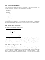
1
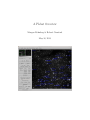
A PhAst Overview
Morgan Rehnberg & Robert Crawford
May 10, 2013
Contents
1 Introduction
1.1 Overview . . . . . . . . . . . . . . . . . . . . . . . . . . . . . . . . . . . . . .
1.2 What’s different about PhAst . . . . . . . . . . . . . . . . . . . . . . . . . .
3
3
3
2 Installing PhAst
2.1 PhAst binary . . . . . . .
2.2 Installing from source . . .
2.2.1 Required packages
2.3 Optional packages . . . . .
2.4 Directory structure . . . .
2.5 The configuration file . . .
2.6 Checking for updates . . .
2.7 Miscellaneous notes . . . .
.
.
.
.
.
.
.
.
5
5
5
5
6
6
6
7
7
.
.
.
.
.
.
8
8
8
8
9
9
9
.
.
.
.
.
.
.
.
.
.
10
10
10
10
10
11
11
11
11
11
11
.
.
.
.
.
.
.
.
.
.
.
.
.
.
.
.
3 Working with multiple images
3.1 Overview . . . . . . . . . . . .
3.2 Adding images . . . . . . . .
3.3 Removing images . . . . . . .
3.4 Refreshing images . . . . . . .
3.5 Navigating the stack . . . . .
3.6 Blinking images . . . . . . . .
4 PhAst features
4.1 Overview . . . .
4.2 Image types . .
4.3 Mouse modes .
4.3.1 Color . .
4.3.2 Zoom .
4.3.3 Blink . .
4.3.4 ImExam
4.3.5 Vector .
4.3.6 Label . .
4.4 WCS features .
.
.
.
.
.
.
.
.
.
.
.
.
.
.
.
.
.
.
.
.
.
.
.
.
.
.
.
.
.
.
.
.
.
.
.
.
.
.
.
.
.
.
.
.
.
.
.
.
.
.
.
.
.
.
.
.
.
.
.
.
.
.
.
.
.
.
.
.
.
.
.
.
.
.
.
.
.
.
.
.
.
.
.
.
.
.
.
.
.
.
.
.
.
.
.
.
.
.
.
.
.
.
.
.
.
.
.
.
.
.
.
.
.
.
.
.
.
.
.
.
.
.
.
.
.
.
.
.
.
.
.
.
.
.
.
.
.
.
.
.
.
.
.
.
.
.
.
.
.
.
.
.
.
.
.
.
.
.
.
.
.
.
.
.
.
.
.
.
.
.
.
.
.
.
.
.
1
.
.
.
.
.
.
.
.
.
.
.
.
.
.
.
.
.
.
.
.
.
.
.
.
.
.
.
.
.
.
.
.
.
.
.
.
.
.
.
.
.
.
.
.
.
.
.
.
.
.
.
.
.
.
.
.
.
.
.
.
.
.
.
.
.
.
.
.
.
.
.
.
.
.
.
.
.
.
.
.
.
.
.
.
.
.
.
.
.
.
.
.
.
.
.
.
.
.
.
.
.
.
.
.
.
.
.
.
.
.
.
.
.
.
.
.
.
.
.
.
.
.
.
.
.
.
.
.
.
.
.
.
.
.
.
.
.
.
.
.
.
.
.
.
.
.
.
.
.
.
.
.
.
.
.
.
.
.
.
.
.
.
.
.
.
.
.
.
.
.
.
.
.
.
.
.
.
.
.
.
.
.
.
.
.
.
.
.
.
.
.
.
.
.
.
.
.
.
.
.
.
.
.
.
.
.
.
.
.
.
.
.
.
.
.
.
.
.
.
.
.
.
.
.
.
.
.
.
.
.
.
.
.
.
.
.
.
.
.
.
.
.
.
.
.
.
.
.
.
.
.
.
.
.
.
.
.
.
.
.
.
.
.
.
.
.
.
.
.
.
.
.
.
.
.
.
.
.
.
.
.
.
.
.
.
.
.
.
.
.
.
.
.
.
.
.
.
.
.
.
.
.
.
.
.
.
.
.
.
.
.
.
.
.
.
.
.
.
.
.
.
.
.
.
.
.
.
.
.
.
.
.
.
.
.
.
.
.
.
.
.
.
.
.
.
.
.
.
.
.
.
.
.
.
.
.
.
.
.
.
.
.
.
.
.
.
.
.
.
.
.
.
.
.
.
.
.
.
.
.
.
.
.
.
.
.
.
.
.
.
.
.
.
.
.
.
.
.
.
.
.
.
.
.
.
.
.
.
.
.
.
.
.
.
.
.
.
.
.
.
.
.
.
.
.
.
.
.
.
.
.
.
.
.
.
.
.
.
.
.
.
.
.
.
.
.
.
.
.
.
.
.
.
.
.
.
.
.
.
.
.
.
.
.
.
.
.
.
.
.
.
.
.
.
.
.
.
.
.
.
.
.
.
.
.
.
.
.
.
.
.
.
.
.
.
.
.
.
.
.
.
.
.
.
.
.
.
.
.
.
.
.
.
.
.
.
.
.
13
13
13
13
13
14
16
16
17
17
18
18
18
19
5 Experimental features
5.1 SPICE . . . . . . . . . . . . . . . . . . . . . . . . . . . . . . . . . . . . . . .
22
22
A Keyboard shortcuts
23
4.5
4.6
4.7
4.4.1 Star overlay . . . . . . . . . .
4.4.2 Search . . . . . . . . . . . . .
4.4.3 Image alignment . . . . . . .
Photometry . . . . . . . . . . . . . .
4.5.1 Overview . . . . . . . . . . .
4.5.2 Aperture centering and sizing
4.5.3 Color terms . . . . . . . . . .
4.5.4 Multi-image photometry . . .
Processing images . . . . . . . . . . .
4.6.1 SExtractor integration . . . .
4.6.2 SCAMP integration . . . . . .
4.6.3 missFITS integration . . . . .
4.6.4 Photometric zero-point . . . .
MPC reporting . . . . . . . . . . . .
B Calibration process
B.1 Overscan correction
B.2 Bias subtraction . .
B.3 Dark subtraction .
B.4 Flat division . . . .
B.5 Binning . . . . . .
B.6 Precession . . . . .
.
.
.
.
.
.
.
.
.
.
.
.
.
.
.
.
.
.
.
.
.
.
.
.
.
.
.
.
.
.
.
.
.
.
.
.
.
.
.
.
.
.
.
.
.
.
.
.
.
.
.
.
.
.
.
.
.
.
.
.
.
.
.
.
.
.
.
.
.
.
.
.
.
.
.
.
.
.
.
.
.
.
.
.
.
.
.
.
.
.
.
.
.
.
.
.
.
.
.
.
.
.
.
.
.
.
.
.
.
.
.
.
.
.
.
.
.
.
.
.
.
.
.
.
.
.
.
.
.
.
.
.
.
.
.
.
.
.
.
.
.
.
.
.
.
.
.
.
.
.
.
.
.
.
.
.
.
.
.
.
.
.
.
.
.
.
.
.
.
.
.
.
.
.
.
.
.
.
.
.
.
.
.
.
.
.
.
.
.
.
.
.
.
.
.
.
.
.
.
.
.
.
.
.
.
.
.
.
.
.
.
.
.
.
.
.
.
.
.
.
.
.
.
.
.
.
.
.
.
.
.
.
.
.
.
.
.
.
.
.
.
.
.
.
.
.
.
.
.
.
.
.
.
.
.
.
.
.
.
.
.
.
.
.
.
.
.
.
.
.
.
.
.
.
.
.
.
.
.
.
.
.
.
.
.
.
.
.
.
.
.
.
.
.
.
.
.
.
.
.
.
.
.
.
.
.
.
.
.
.
.
.
.
.
.
.
.
.
.
.
.
.
.
.
.
.
.
.
.
.
.
.
.
.
.
.
.
.
.
.
.
.
.
.
.
.
.
.
.
.
.
.
.
.
.
.
.
.
.
.
.
.
.
.
.
.
.
.
.
.
.
.
.
.
.
.
.
.
.
.
.
.
.
.
.
.
.
.
.
.
.
.
.
.
.
.
.
.
.
.
.
.
.
.
.
.
.
.
.
.
.
.
.
.
.
.
.
.
.
.
.
.
.
.
.
.
.
.
.
.
.
.
.
.
.
.
.
.
.
.
.
.
.
.
.
.
.
.
.
.
.
.
.
.
.
.
.
.
.
.
.
.
.
.
.
.
.
.
24
24
24
24
25
25
25
C Programming with PhAst
C.1 Overview . . . . . . . . . .
C.2 PhAst program structure .
C.2.1 PhAst index . . . .
C.2.2 Compilation order
C.2.3 Execution order . .
C.3 Common blocks . . . . . .
C.3.1 phast state . . . .
C.3.2 phast images . . .
C.4 The image object . . . . .
C.5 The image stack . . . . . .
.
.
.
.
.
.
.
.
.
.
.
.
.
.
.
.
.
.
.
.
.
.
.
.
.
.
.
.
.
.
.
.
.
.
.
.
.
.
.
.
.
.
.
.
.
.
.
.
.
.
.
.
.
.
.
.
.
.
.
.
.
.
.
.
.
.
.
.
.
.
.
.
.
.
.
.
.
.
.
.
.
.
.
.
.
.
.
.
.
.
.
.
.
.
.
.
.
.
.
.
.
.
.
.
.
.
.
.
.
.
.
.
.
.
.
.
.
.
.
.
.
.
.
.
.
.
.
.
.
.
.
.
.
.
.
.
.
.
.
.
.
.
.
.
.
.
.
.
.
.
.
.
.
.
.
.
.
.
.
.
.
.
.
.
.
.
.
.
.
.
.
.
.
.
.
.
.
.
.
.
.
.
.
.
.
.
.
.
.
.
.
.
.
.
.
.
.
.
.
.
.
.
.
.
.
.
.
.
.
.
.
.
.
.
.
.
.
.
.
.
.
.
.
.
.
.
.
.
.
.
.
.
.
.
.
.
.
.
.
.
.
.
.
.
.
.
.
.
.
.
.
.
.
.
.
.
.
.
.
.
.
.
.
.
.
.
.
.
.
.
.
.
.
.
.
.
.
.
.
.
26
26
26
26
26
26
27
27
27
27
28
.
.
.
.
.
.
.
.
.
.
.
.
.
.
.
.
.
.
2
Chapter 1
Introduction
1.1
Overview
PhAst is an interactive astronomical image display program, built on ATV 2.3. It is written
in IDL. PhAst allows the user to open, view, and process multiple images in the popular
FITS format.
1.2
What’s different about PhAst
PhAst is a fork of Aaron Barth’s ATV project at the 2.3 release. The project aims to expand
ATV in three ways:
1. Redesign the GUI for use with modern widescreen displays
2. Provide support for multi-image analysis
3. Integrate outside tools to streamline the data reduction process
ATV’s GUI is vertically oriented, while modern displays have become increasingly horizontal.
PhAst attempts to make use of this newfound horizontal real estate by moving the main
control panel to the left of the display window. For example, maximizing ATV tends to
simply expand the menu panel far beyond what is needed, while expanding the image an
equal amount. In PhAst, the menu panel remains fixed at all times, and any change in the
program’s size is directly translated into an increased image size.
Although ATV provides rudimentary support for blinking up to three images, only a
single image is retained in memory at any given time. For example, if a user opens an
image, scales it for blinking, then opens a second image and stretches it, these changes
are not applied back to the initial image, which is now lost from memory. This process is
useful for images of different exposure, but many sets of astronomical images have identical
exposure and a single adjustment should be applied to all of them. By storing all images
in an expandable stack, PhAst allows the user to manipulate any number of images, adjust
them as a group, and animate through them all.
3
Finally, although ATV offers a robust photometry tool, it does not address astrometry
other than support for existing WCS coordinates. PhAst also does not include a dedicated
astrometry package, but it integrates with Emmanuel Bertin’s excellent SExtractor and
SCAMP tools for solving images. Including this capability also allows PhAst to expand its
use of WCS coordinates, since the user can always use the astrometry pipeline to add them
to his images.
4
Chapter 2
Installing PhAst
2.1
PhAst binary
PhAst is available in binary form from http://www.noao.edu/noao/staff/mighell/phast/.
The binary is required for any user who does not have a valid IDL license. Running the binary
requires the IDL Virtual Machine, available from http://www.exelisvis.com.
2.2
Installing from source
If you wish to modify PhAst, you must install it from source. The latest stable version is
available from http://www.noao.edu/noao/staff/mighell/phast/. There is also a Git
repository located at http://github.com/forceflow1049/phast. This repository contains
past code versions plus the latest in-development version, which is likely to be unstable.
Move the directory containing PhAst to the location in which you want it installed.
Launch IDL and type ‘phast install’. This will add the current location to your IDL path
and check for the presence of the NASA Astronomy User’s Library and the Coyote Library,
which are required for operation. Once PhAst is installed, you can run it from any directory
by typing ’phast’ at the IDL prompt.
NOTE: PhAst requires IDL 8.0 or later to run.
2.2.1
Required packages
The main PhAst application is contained in a single IDL procedure, phast.pro. The following
packages are also required:
• The NASA IDL Astronomy User’s Library
• The Coyote Library
5
2.3
Optional packages
PhAst also supports a pipeline of reduction tools, designed to expedite data analysis. The
following packages are optional, but will extend PhAst’s capabilities:
• SExtractor
• SCAMP
• missFITS
• zeropoint.param
• read vicar.pro
• vicgetpars.pro
See section 4.6 for more information on the features involving these packages. If you are using
the binary version of PhAst, the files read viar.pro and vicgetpars.pro are already included.
2.4
Directory structure
The PhAst directory structure should look like:
phast/
phast.pro
phast install.pro
lib/
output/
catalogs/
images/
PhAst requires an output directory named output in the same directory as the main
program. The directories catalogs and images must exist inside of output. If PhAst is started
and these directories are not found, it will ask to create them. Not creating these directories
will cause PhAst to behave incorrectly and possibly crash. The images sub-directory can
always be cleared by selecting File>Remove and selecting to empty the output directory.
2.5
The configuration file
Since PhAst is a GUI application, no configuration file is required for operation. Support for
a configuration file is provided, however, to allow the user to set commonly used parameters
to a desired value. If a configuration file is desired, create the file phast.conf in the same
directory as the main program. Parameters can be set in the form parameter
value,
where a single tab separates the parameter and its value. Do not place quotes around string
6
values. Naturally, not all program variables can be set via the configuration file. Allowable
parameters are listed in tables throughout this manual.
2.6
Checking for updates
You can check for updates to PhAst from within the application. Simply choose Help>Check
for updates. By default, PhAst will check for updates every time it is started. Automatic
update checking is a silent process - you will only be notified when a new version is available.
Parameter
Default Type Description
check updates 1
0/1
check for updates on
startup?
2.7
Miscellaneous notes
Because PhAst deals with large data files (in the form of images), it is rather dependant
on a high-bandwidth, low-latency connection. It is always best to run PhAst from the local
machine, or a machine on the local network. If you absolutely must run the program over
the public internet, please be patient! It can take up to ten seconds for certain actions to
load completely (ie, examing a star’s photometry).
7
Chapter 3
Working with multiple images
3.1
Overview
A major advantage of PhAst over ATV is the ability to examine and process multiple images
at once. This greatly expands the user’s image comparison options. Although only one image
can be displayed on the screen at a time, all added images are stored in an stack, where they
can be readily accessed.
3.2
Adding images
Images can be added either one-by-one, or in entire directories. Adding single images has
one potential advantage: packed (i.e., .fz) files can be loaded. Directory adding is limited
to uncompressed images. FITS files can be added to the stack by choosing File>Read and
selecting either a single image or an entire directory. Images are always added to the end of
the stack. If an entire directory has been added, the images are added in the order in which
they appear in the directory.
3.3
Removing images
A currently displayed image can be easily removed from the image stack. This is useful
for an accidental image selection or when a poor-quality image is identified. Images can be
removed by selecting File>Remove and choosing either to remove the current image or all
images. The image(s) will be removed, the stack will be collapsed, and the next available
image will be displayed. If all images are removed, any loaded catalog data is erased (see
section 4.4.1 for more information).
8
3.4
Refreshing images
If the user modifies an image while it is in the stack, such modifications may not automatically
be reflected in the archived image. Refreshing an image reloads it from disk, which will
update the archived image to the latest version. This can be done by selecting File>Refresh
and selecting to refresh either the current image or all archived images. Some processes,
such as computing the photometric zero-point will automatically refresh the image upon
completion.
3.5
Navigating the stack
Images can be quickly skimmed through with the arrow buttons located directly under the
pan and track mini-windows. The user can also jump to any desired image by selecting
it from the drop down list. More advanced navigation options are available in the Blink
Control toolset, discussed in section 3.6. The keyboard shortcuts Page Up / Page Down can
also be used to move forward and backwards through the stack. The Home key will jump to
the first image and the End key will jump to the last.
3.6
Blinking images
The arrangement of working images into the stack makes blinking easy. Simply add the
images in the order you wish them to be animated. The blink control toolbox provides an
easily-accessible method for controlling the blinking process. To start a blink, simply press
the play button. The images will begin to animate through at their default rate. This rate
can be controlled with the Animate Speed slider. Three animation types are offered: forward, backward, and bounce (where the images are played forwards and then backwards).
The animation can be stopped by pressing the pause button.
Parameter
animate speed
Default
0.4
Type
float
Description
time (in sec) per image on
[0.1,1]
animate type
forward string forward/backward/bounce
tb blink visible 1
0/1
draw the blink controls?
tb blink toggle 1
0/1
expand blink controls initially?
9
Chapter 4
PhAst features
4.1
Overview
The following is an incomplete list of notable, non-obvious features of PhAst. For a more
complete listing of basic functionality, see the documentation for ATV.
4.2
Image types
PhAst is primarily designed to view FITS images. It does not currently support FITS
spectra. As of version 1.1, there is experimental support for NASA’s VICAR image format,
used on some spacecraft missions. These images can be opened by going to File > Read
and selecting Read VICAR Image. VICAR images can be opened in the same session as
FITS images. Pipeline features such as SExtractor and SCAMP execution do not work with
VICAR images.
4.3
Mouse modes
ATV is built around a series of mouse modes, which define the behavior of mouse clicks on
the main images. PhAst adds an additional mouse mode, Label. PhAst also changes the
default mouse mode from Color to ImExam.
4.3.1
Color
While in Color mode, click and drag to adjust the brightness and contrast of the displayed
image. Image adjustments are carried through to all opened images.
Parameter
Default Type Description
invert colormap 0
0/1
invert image by default?
10
4.3.2
Zoom
While in Zoom mode, left-clicking magnifies the image and right-clicking demagnifies the
image. Middle-clicking will center the image on the clicked pixel.
4.3.3
Blink
PhAst places less emphasis on the blink mouse mode than does ATV, instead relying on the
Blink Control toolbox on the left pane. Clicking the mouse in blink mode will rapidly blink
through up to three images, defined by choosing Blink>SetBlink1, etc from the menu bar.
This method of blinking does not take into account any further changes made to the images
(see section 3.6).
4.3.4
ImExam
ImExam mode allows basic information about a given region of the image to be quickly
viewed. Left-clicking in ImExam mode displays the photometry window (see section 4.5),
while right-clicking displays basic statistics. Middle-clicking centers the clicked pixel on the
display area.
4.3.5
Vector
Click and drag in Vector mode to generate a 1-D spectrum of pixel brightnesses.
4.3.6
Label
The label mouse mode is new to PhAst. It provides a simpler interface to commonly performed labeling tasks. Left clicking while in label mode brings up the label region dialog,
usually accessed through Labels>Region. In label mode, this form is automatically populated with the coordinates of the mouse click. The user can either left-click or left-click and
drag to activate this feature. If only a click is performed, the radius is set to 10 px, allowing
small circles to be quickly placed. If the user also drags, the radius of the circle will be set
as the distance from mouse-press to mouse-release.
If the right mouse button is pressed, a text label can be placed on the image. A dialog
box will popup for input and the label will be placed at the location of the mouse click.
Figure 4.1 shows some of the available annotations.
4.4
WCS features
PhAst supports World Coordinate System coordinates encoded in the FITS header. As the
user mouses over an image, the left panel displays the current cursor position in terms of
RA and Dec, as well as x,y image coordinates. The coordinate system can be changed in the
ImageInfo menu category. The current image rotation is indicated by arrows showing north
11
Figure 4.1: Images can be annotated with text labels and shapes.
12
and east on the overview image. PhAst also makes use of WCS for both reference catalog
lookup and image alignment.
4.4.1
Star overlay
Any image with valid WCS can have known catalog stars overlaid on the image. This is
controlled by the Overlay Stars toolset on the left panel. The user can select the limiting
magnitude down to which stars will be overlaid, and whether or not the names should be
displayed (as opposed to just the positions). The default catalog for reference stars is USNOB1.0, which is an online catalog. The catalog can be changed by selecting ImageInfo>Select
Catalog.
Parameter
Default Type Description
tb overlay visible 1
0/1
Draw star overlay toolbox?
tb overlay toggle 0
0/1
Expand star overlay toolbox
initially?
4.4.2
Search
If you have valid WCS and access to a catalog, you can search the current image for a known
catalog star. This is useful if you are searching a dense field for a particular star. To perform
a search, simply type the catalog name into the search box at the bottom of the Overlay
Stars toolbox and press search. If the specified star is present in the current image, it’s
position and name are overlaid on the screen, in the same fashion as the star overlay option.
4.4.3
Image alignment
Images with valid WCS can also be aligned (registered), so that the fixed stars remain in
place. This is especially useful when blinking images. Aligning the images will help any
moving object in the field stand out despite any field motion. Image alignment can be selected in the basic stack navigation toolbox, directly under the pan and track mini-windows.
Parameter
Default Type Description
align toggle 0
0/1
align images? 1=yes
If an image does not have WCS coordinates, these features are unavailable. The proper
pointing data, however, can be written to the FITS header of each image as part of the
pipeline process.
4.5
4.5.1
Photometry
Overview
PhAst maintains ATV’s aperture photometry package, modifying it only to facilitate photometry over multiple images. The photometry window can be opened either by choosing
13
ImageInfo>Photometry or left-clicking while in the ImExam mouse mode. Two new buttons have been added to the photometry window, allowing the user to cycle through the
images in the image stack. Once a star is selected, these buttons can be used to examine
the photometry of the same star in several images. Note that this feature currently makes
use of ATV’s ability to snap to a nearby star. If your field shifts dramatically from image to
image, or your field is particularly dense, use this feature with caution. The snap-to radius
can be adjusted with the Centering box size field.
4.5.2
Aperture centering and sizing
PhAst offers three methods for centering the photometric aperture on a target:
• Snap to centering (inherited from ATV) in which the apertures are re-centered on the
brightest pixel within the measuring aperture before the centroid is computed. The
method attempts to find the object nearest to the location of the users mouse click.
• Flux centering, based on the x-y centroid of the flux contained within the inner sky
aperture (to account for all of the flux) after subtracting the median sky background
from total counts. The calculation is performed twice: first, based on the user’s manual
positioning of the cursor; second, based on the centroid computed in the first pass.
The two-pass approach largely eliminates the influence of the user’s initial manual
positioning on the calculated centroid.
• Manual centering (inherited from ATV) in which the center of the whole pixel on
which the user has clicked is taken as the centroid of the object and used to center the
apertures.
The default centering method is snap to. The x-y position of the center of the aperture is
also the basis for any astrometric position computed by PhAst.
When the program starts, the photometry apertures are sized automatically to cover
defined fractions of the flux in a 2D Gaussian profile using the current value of PhAsts
estimate of FWHM in images. The default value is 1.3”. The sizing algorithm is:
1. The measurement aperture is sized to contain 72% of the flux for a 2D Gaussian PSF.
This is considered to be the optimum for aperture measurements, because the sky noise
grows more rapidly than the object flux beyond this point, leading to deterioration in
the SNR. Once measured, the flux value (and error) are grown to give a total flux
coverage of 90% or 94%. A theoretical growth curve based on the integrated volume
under a circular 2D Gaussian PSF is used for this purpose.
2. The inner sky aperture is set so that 99.9% of the flux for a Gaussian PSF is contained
within it, and essentially no object flux contaminates the sky annulus.
3. The outer sky aperture is set so that the sky annulus contains at least 200 pixels from
which to determine the sky contribution.
14
Figure 4.2: The photometry window in its default state.
15
4.5.3
Color terms
As discussed below, PhAst has the capability to determine the photometric zeropoint of an
image and will include a color term in the determination by default. PhAst provides two
methods for selecting the color of an observed object. The object’s spectral type (B-M,
0-9) can be selected from the photometry window and the appropriate color terms will be
retrieved from a standard table. Alternatively, the color terms can be explicitly provided.
The default spectral type is K0.
4.5.4
Multi-image photometry
The Do all button allows you to perform a photometric measurement at this point on all
images. This is useful for recording a lightcurve for an object. For example, to write photometric data for an objext over a set of images, you would do the following (see Figure ??):
1. Set mouse mode to ImExam
2. Click on object of choice (use star name overlay to find, if necessary)
3. Click Write results to file... and choose a filename
4. Click Do all
5. Click Close photometry file
This file will contain the photometric readings and error estimates for the object in each of
your images.
Parameter
ccdgain
ccdrn
ccdrotangle
innersky
magunits
outersky
photerrors
photfilename
phot rad plot
pixelscale
seeing
skytype
Default
1.0
0.0
90.0
10.0
0
Type
float
float
float
float
0/1
Description
ccd gain
ccd readnoise
rotation of ccd in deg
inner sky radius
Units: 0=counts, 1=magnitudes
20.0
float
outer sky radius
0
0/1
calculate photometric error? 1=yes
phastphot.dat string filename of output photometry data file
open 1
0/1
show radial plot of photometry by default?
1.0
float
pixel scale in arcseconds
2*pixelscale
float
seeing in arcseconds
0
int
sky
subtraction
type:
0=idlphot,
1=median,
2=none
16
4.6
Processing images
PhAst provides a flexible option for calibrating images. To access the calibration features,
choose Pipeline>Process images from the top menu. The calibration window allows the
user to select an image to be calibrated, as well as a dark, flat, and bias image, if desired.
Check the tickboxes for the calibration types you wish to use, and then select an image to
correspond to each. Checking the overscan correct box will subtract any present overscan
region from each image and then trim this region from the file. Custom binning values can
be supplied to resize an image. For a detailed description of the calibration process, see
section B.
NOTE: Binning an image will change its plate scale, which must be accounted for in
other configuration files!
Parameter
bias file
Type Description
string bias file to be used for
bration
cal file name ./output/images/phast.fits string default filename for
brated image
string dark file to be used for
dark file
bration
flat file
string flat file to be used for
bration
4.6.1
Default
-
calicalicalicali-
SExtractor integration
The currently displayed image can be plate-solved with SExtractor to extract any objects
present. To use this feature, you must have a version of SExtractor installed such that it
can be called via the command line with the command sex. In addition, the appropriate
configuration files must be configured and placed in the same directory as PhAst. A text box
is also given to allow you to pass commands to SExtractor. These commands are passed in
the form of OPTION NAME VALUE. For more information regarding SExtractor options,
see its manual.
NOTE: SExtractor requires a number of configuration files to run. These files must be
present in the same directory as phast.pro. The purpose of these files is described in the
SExtractor manual.
17
Parameter
Default Type Description
compute astrometry 0
0/1
Compute astrometry?
string path to where SExtractor
sex catalog name
catalog is placed
sex flags
string list of SExtractor flags. Use
one space between flags
fits crota1
0
float
RA field rotation
fits crota2
0
float
Dec field rotation
float
RA plate scale
fits cdelt1
fits cdelt2
float
Dec plate scale
4.6.2
SCAMP integration
If a source list has been created using SExtractor, PhAst runs SCAMP to find an astrometric
solution and write those coordinates to the FITS header. If there is significant uncertainty
in an image’s pointing data, you may need to relax SCAMP’s error tolerance. Consult the
SCAMP manual for the exact procedure to make this change.
NOTE: If your images do not contain the CROTA and CDELT keywords in their FITS
headers (or the data is incorrect), SCAMP will not solve them correctly. Use the configuration file parameters listed below to provide or override the rotation and plate scale.
Parameter
scamp flags
Default
-
Type
string
fits
fits
fits
fits
0
0
-
float
float
float
float
4.6.3
crota1
crota2
cdelt1
cdelt2
Description
list of SCAMP flags. Use
one space between flags
RA field rotation
Dec field rotation
RA plate scale
Dec plate scale
missFITS integration
Once a SCAMP solution is found, PhAst will use missFITS to write this data to the header
of the calibrated image.
Parameter
Default Type Description
missfits flags string list of missFITS flags. Use
one space between flags
4.6.4
Photometric zero-point
If an image has been solved, and its WCS coordinates written to the FITS header, PhAst can
use an external catalog to calculate the photometric zero-point. To calculate the zero-point
for the currently displayed image, choose Pipeline>Photometric zero-point and click start.
18
The photometric zero-point will be calculated based on data from the currently selected
catalogand written to the FITS header with the keyword MAGZERO. By default, the GSC2.3.2 star catalog is used during the zero-point computation.
To determine catalog magnitudes, the flux coverage of the measuring aperture must be coordinated with the size of SExtractors elliptical apertures. This is done automatically based
on the SExtractor parameter PHOT AUTOPARAMS[0]. If the value is 2.0, then the flux is
grown to 90% coverage. If the value is 2.5, then the flux is grown to 94% coverage. These
choices will be made (and the coverage ratio set) even if the user will simply measure instrumental magnitudes with PhAst. The default for PhAst is PHOT AUTOPARAMS[0] = 2.5
and a flux coverage ratio of 94%.
PhAst offers the option to report measurements as calibrated or absolute magnitudes.
PhAst will solve for the zero-point and color-term coefficient of the filter passband used in
the image. The solution involves matching the objects detected in the image to entries in
the GSC-2.3.2 catalog by position. The GSC-2.3.2 catalog is derived from the same all-sky
Schmidt sky survey used by the USNO-B1.0 catalog, but has superior photometry in the
photographic B and R bands. The B-R color term is used in the zero-point determination.
This method requires that the image have a valid astrometric solution to support the match
of image stars to the catalog. To determine the zeropoint, a weighted linear regression
analysis is performed to relate instrumental magnitudes to the R band catalog magnitude,
with outlier rejection at the 2.4-sigma level (2 percent chance of false positive). Z0 (zeropoint)
and Zc (color term) coefficients. are estimated.
A limitation of PhAsts zeropoint determination at present is that it operates on images individually. It can account for varying instrumental zeropoints by image (e.g., due to
non-photometric conditions) only in the fit to catalog magnitudes. If the ensemble of catalog stars varies by image in the fits, the varying zeropoints may not be completely controlled.
NOTE: The file zeropoint.param must be present in the same directory as phast.pro for
zero-point calibration to work.
NOTE: For technical reasons, processing currently does not automatically compute the
photometric zero-point for images. This must be performed separately on each image.
4.7
MPC reporting
If a set of images have been properly calibrated with WCS and photometric zero-point data,
PhAst can generate an object report for the Minor Planets Center (MPC). To prepare an
MPC report, select ImageInfo>MPC report. You will be presented with three tabs to walk
you through the report creation process. The Info tab displays the site and observer information to be included in the report. This information can be specified using the configuration
file (see end of section for appropriate keywords). The data tab allows the user to select the
data points they wish to select. With MouseMode ImExam selected, click Choose a data
point and then click on the object in the image. The photometry window will appear. Use
19
Figure 4.3: PhAst’s batch processing allows for the calibration of an entire directory of files,
or all currently loaded files.
20
it to confirm you have selected the correct target and that the object’s magnitude seems
appropriate. When you are satisfied that the correct object has been selected, click Add
selected point to store the point for reporting. Up to five points can be stored for reporting.
After at least two points have been selected, clicking the Check Plots tab will display plots
of RA,Dec, and Magnitude vs time, as well as the computed velocity and position angle.
This information can be used to help determine whether a suspected detection is real.
Parameter
Default
mpc ack
mpc code
mpc com
mpc contact address mpc contact email
mpc contact name
mpc height
mpc lat
N
mpc lat dir
mpc lon
mpc
mpc
mpc
mpc
mpc
mpc
mpc
mpc
lon dir
observers
measurer
net
note1
note2
site code
telescope
Type
string
char
string
string
string
string
float
float
N/S
float
W
E/W
string
string
USNO-B1.0 string
char
char
int
string
21
Description
MPC report ACK line
single character code
MPC report comment
Contact address
Contact email
Contact person’s name
Observatory elevation (m)
Observatory latitude (deg)
Is lat north or south?
Observatory
longitude
(deg)
Is the lon east or west?
Observers’ names
Measurer’s name
MPC NET line
MPC note 1 (see standard)
MPC note 2 (see standard)
MPC site code
Telescope name
Chapter 5
Experimental features
The features described in this section probably don’t work. If they do work, they are probably
riddled with bugs. Even if you survive the bugs, these features probably aren’t useful to
you. You have been warned!
5.1
SPICE
The SPICE system is a software suite developed to provide the location and trajectories of
all major objects in the solar system, including planets, moons, and spacecraft.
SPICE integration in PhAst currently allows the user to check whether their VICAR
image contains any moons of Saturn and plots their position and range on the image. To
use this feature, you must enable it in phast.conf and have the IDL SPICE package (ICY)
properly installed and configured. SPICE kernels to be loaded should be listed, one per line,
in a file specified by the parameter kernel list. The default is kernels.txt.
Parameter
Default
tb spice visible 0
tb spice toggle 0
kernel list
kernels.txt
Type
0/1
0/1
Description
draw the SPICE controls?
expand SPICE controls initially?
string file containing list of kernels
to load
22
Appendix A
Keyboard shortcuts
Below is a table of keyboard shortcuts available in PhAst. Note that the image part of the
main window must have focus for keyboard shortcuts to be recognized.
Key
c
e
h
i
m
p
q
r
s
t
x
Down
End
Home
Left
Page Down
Page Up
Right
Up
Description
column plot
erase annotations
histogram of pixel values
image statistics
cycle mouse modes
photometry
quit PhAst
row plot
surface plot
contour plot
extract spectrum
move mouse cursor down
last image
first image
move mouse cursor left
previous image
next image
move mouse cursor right
move mouse cursor up
23
Appendix B
Calibration process
The calibration process used by PhAst is described below. If any of the calibration images
are omitted, then the corresponding calibration step is not performed. If the bias frame is
omitted, the bias value is assumed to be 0.
B.1
Overscan correction
If the overscan correction tickbox has been selected, all the images have their overscan
subtracted. The FITS keyword BIASSEC is found and parsed for the bias region. For every
row in the image, the median value from that row’s bias region is found and subtracted from
each other element. This process occurs for the science, dark,flat, and bias images (or any
that have been provided). The overscan is then trimmed from the images.
B.2
Bias subtraction
The bias image is now subtracted from the science image on a pixel-by-pixel basis. A floor
of zero is placed on each resulting value, preventing negative counts.
B.3
Dark subtraction
The bias frame is first subtracted from the dark frame. Since the dark frame could have
a different exposure length than the science image, it must then be scaled to reflect this
different. The EXPTIME keyword is extracted from both FITS headers and the ratio is
used to scale the dark frame. Once scaled, the dark is subtracted from the science on a
pixel-by-pixel basis.
24
B.4
Flat division
The bias frame is first subtracted from the flat frame. The dark frame is then scaled to
match the flat’s exposure time as described in the previous section. This scaled dark is then
subtracted from the flat. The median value of a region defined by the middle 50% of each
dimension is then computed. A flat map is then created by dividing the flat by this median
value. The science image is then divided by this flat map.
B.5
Binning
Images are binned in the x and y directions using the FREBIN procedure. Surface flux is
conserved.
B.6
Precession
Images whose equinox or epoch is not J2000 will be precessed to J2000. The IDL Astronomy
User’s Library procedure precess is used to perform the precession and the FITS header is
updated to reflect the new equinox.
25
Appendix C
Programming with PhAst
C.1
Overview
PhAst is open-source software and you are encouraged to modify it for your own purposes.
To assist in this, this appendix will describe the basic internal structure of PhAst.
C.2
C.2.1
PhAst program structure
PhAst index
An index file, index.txt, is located in the lib/ directory and lists the location of every PhAst
procedure.
C.2.2
Compilation order
The main procedure, phast.pro compiles and calls a series of additional procedures located
in the lib/ directory. They are compiled in alphabetical order so prepending a filename with
aaax will set it’s compile order. Note that aaaa, aaab, and aaac are already reserved.
C.2.3
Execution order
Starting PhAst results in the following initial procedure calls:
1. phast.pro
2. phast compile modules.pro
3. phast startup.pro
4. phast initcommon.pro
26
5. phast read config.pro
Once these procedures are called, PhAst should be sitting idle on its launch screen.
C.3
C.3.1
Common blocks
phast state
The phast state common block holds the values of all program-wide variables. It includes
things such as the number of images loaded, the current image displayed, and the current
astrometric catalog as well as interface states, like whether the blink widget is currently
visible. If you want to add a system-wide value, create a new line in the state structure
definition in the procedure phast initcommon. Variables that do not need global scope should
not be placed here and should be confined to their respective procedure or function. This
helps avoid namespace overlap and increases performance.
C.3.2
phast images
This common block contains copies of all the images PhAst needs, including both the temporary display copies and stored stack version. The image stack is known as the image archive
in the code. The image archive is an array which holds all the image objects created from
loaded images.
C.4
The image object
Images stored in the image stack are contained in objects. These objects are defined by the
phast image define procedure and have the class name phast image. Each object has local
pointers to the following data:
• image: the array containing the image data
• header : contains the data from the FITS header
• name: a string containing the pathname to the file originally loaded into PhAst
• size: a two-element array containing the x-y size of the image in pixels
• rotation: a float containing the rotation of the image in degrees, measured from the
image’s initial orientation on loading
• astr : contains the astrometric data, if available
Data can be altered and retrieved from the image object through the typical set of helper
functions.
27
C.5
The image stack
The image stack is an array which contains the image objects for all images loaded into
PhAst. It is called the image archive and located in the phast images common block. Images
can be added to the stack through the phast add image procedure and removed via the
phast remove image procedure.
28