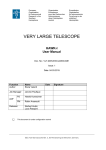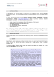
1
European
Organisation
for Astronomical
Research in the
Southern
Hemisphere
Organisation
Européenne
pour des Recherches
Astronomiques
dans l’Hémisphère
Austral
Europäische
Organisation
für astronomische
Forschung in der
südlichen
Hemisphäre
VERY LARGE TELESCOPE
ADAPTIVE OPTICS FACILITY
HAWK-I/GRAAL Observation Preparation
Doc. No.: VLT-SPE-ESO-22000-5838
Issue: 2
Date: 31.01.2015
Function
Author
Name
Ralf Siebenmorgen
Job Manager
Jerome Paufique
PS
Harald Kuntschner
PM
Robin Arsenault
Date
Signature
AOF
Releaser
Norbert Hubin
Luca Pasquini
This document is under configuration control
ESO, Karl-Schwarzschild-Str. 2, 85748 Garching bei München, Germany
HAWK-I/GRAAL
Observation Preparation
Doc:
Issue
Date
Page
VLT-SPE-ESO-2200-5838
2
31.01.15
2 of 19
CO-AUTHORS
Co-Authors
Jerome Paufique
Harald Kuntschner
Affiliation, Division
ESO, INS
ESO, INS
REVIEWERS
Reviewers
HAWK-I IOT
P.-Y. Madec
L. Tacconi-Garman
Affiliation, Division
G. Carraro et al.
ESO, INS
ESO, DMO
CHANGE RECORD
ISSUE
0.3
0.6
1
2
DATE
11.03.13
09.04.13
25.04.13
31.01.15
SECTION/PARA.
AFFECTED
All
All
All
Table 1
REASON/INITIATION
DOCUMENTS/REMARKS
Initial draft
Major update by HKU et al
Issue 1
Issue 2 by EVA, RSI
HAWK-I/GRAAL
Observation Preparation
Doc:
Issue
Date
Page
VLT-SPE-ESO-2200-5838
2
31.01.15
3 of 19
TABLE OF CONTENTS
1 2 3 4 5 Scope ......................................................................................................................... 4 List of Abbreviations & Acronyms............................................................................... 4 List of Applicable and Referenced Documents .......................................................... 5 Observations Preparation Software Tool ................................................................... 5 Use cases ................................................................................................................ 15 5.1 UC – Definition of non-AO HAWK-I observation in Phase 2.............................. 15 5.2 UC – Definition of AOF mode HAWK-I/GRAAL observation in Phase 2 ........... 17 6 Conclusion................................................................................................................ 18 HAWK-I/GRAAL
Observation Preparation
1
Doc:
Issue
Date
Page
VLT-SPE-ESO-2200-5838
2
31.01.15
4 of 19
Scope
Requirements on the HAWK-I/GRAAL observation preparation, the so-called
GuideCam tool, are given. This tool will be used by observers in Phase 2
preparation to enable the selection of the natural guide star used for AOF tip-tilt
corrections and optionally the separate VLT guide star. The tool produces a
observing setup for the HAWK-I/GRAAL acquisition that is used by p2pp and in
addition provides VLT compliant finding charts. A direct link between the tool and
p2pp allows the user to automatically upload the relevant AOF parameters into the
HAWK-I acquisition templates.
2
List of Abbreviations & Acronyms
This document employs several abbreviations and acronyms to refer concisely to
an item, after it has been introduced. The following list is aimed to help the reader
in recalling the extended meaning of each short expression:
2MASS
Two Micron All Sky Survey
AO
Adaptive Optics
AOF
Adaptive Optics Facility
BOP
Bright Object Protection
DSS
Digitized Sky Survey
ESO
European Southern Observatory
FOV
Field of View
NGS
Natural Guide Star
P2PP
Phase 2 Proposal Preparation Tool
TBC
To Be Clarified
TBD
To Be Defined
TT
Tip Tilt
TTS
Tip Tilt Wave Front Sensor
HAWK-I/GRAAL
Observation Preparation
3
VLT-SPE-ESO-2200-5838
2
31.01.15
5 of 19
List of Applicable and Referenced Documents
RD1
RD2
RD3
RD4
RD5
4
Doc:
Issue
Date
Page
Top-Level Requirements for the
Adaptive Optics Facility (AOF)
HAWK-I User Manual
VLT-SPE-ESO-112504375
VLT-MAN-ESO-148003486
Calabretta, M. R., Greisen, E. W., 2002, Representations of
A&A, 395, 1077
celestial coordinates in
FITS
Observation Preparation and Observer
VLT-SPE-MUS-14670Support Software Tools Specifications
0628
HAWK-I Template Reference Guide
VLT-MAN-ESO-148004076
Observations Preparation Software Tool
The typical observing sequences are described in RD2. We describe in this
section the specific field selection software tool that will help the user to prepare
the observations. They are supposed to be executed during the preparation of
P2PP. The requirements are written in a rather verbose style to ease the reading.
The Guide Cam tool shall allow the user to define the precise field centre,
instrument orientation (position angle on sky) and the natural guide star locations
of suitable GRAAL tip-tilt star candidates (GRAAL TT-star) and the VLT guide star.
The tool prepares the necessary input for p2pp (acquisition template) and
supports the production of VLT compliant finding charts.
R1.
Selection modes
The user can select one out of three available observing modes:
- Non-AOF mode
- AOF TT-star-free mode
- AOF mode (standard)
The Non-AOF mode covers the currently available observing modes of HAWK-I
where only field centre, instrument orientation, target offset and optionally the VLT
guide star position can be defined. This mode is useful when the user is not
interested in any AO correction but rather desires the shortest possible setup times
(e.g. bright star photometry, transient objects).
The AOF TT-star-free mode allows the setup of the instrument when no suitable
GRAAL TT-star is available but some degree of AO correction is still desired and
can be realized via the Laser Guide Star only. For instruments like SINFONI this is
referred to as “seeing enhancer” mode. Here the field centre, instrument
HAWK-I/GRAAL
Observation Preparation
Doc:
Issue
Date
Page
VLT-SPE-ESO-2200-5838
2
31.01.15
6 of 19
orientation, target offset and optionally the VLT guide star position can be defined.
The telescope is set into AOF-mode and the necessary preparations for AOF
support (e.g. laser) are started.
The AOF mode allows the full setup of the instrument configuration including the
GRAAL TT-star position.
The Guide Cam tool starts in AOF mode by default.
R2.
Swap between modes
It is possible to swap between observing modes at any time. Previous settings,
which are common to the modes, are preserved while swapping between modes
(especially the field centre and the instrument position angle) as long as they are
not overwritten by an action of the user.
R3.
Guide Cam input
The Guide Cam main input data are the
•
•
•
target coordinate (in J2000, mandatory input),
the optional science target offset (default 0.0, 0.0 or undefined to begin
with in AOF mode)
the optional instrument position angle (default: 0° or undefined to begin
with in AOF mode).
Optional further input data are the catalogue search magnitude ranges for
•
•
•
VLT guide stars (default 8 < R < 13.5 mag; latter values are TBC and
shall be coded as parameters).
Jitter box width (default 5”, max range 5 … 60” for NonAOF and AOF
TT-star-free modes and 0 … 50” for AOF mode).
GRAAL TT-star (default 6 < R < 14.5 mag, max range 6 … 18 mag,
(values are TBC and shall be coded as parameters).
For Non-AOF and AOF TT-star-free modes the mandatory target coordinate, the
optional science target offset (default 0.0, 0.0) and optional instrument position angle
(default 0) are used to draw the HAWK-I FOV in the Guide Cam tool (see R4).
For the standard AOF mode, at the beginning of the selection process only the
mandatory target coordinate is used to indicate all possible TT-star candidates in the
FOV considering the full range of possible target offsets and instrument position
angles. This allows for maximum flexibility to choose the best suited TT-star (see R4).
The input data (see above) can be interactively changed within the allowed limits at
any time and the field configuration with the corresponding set of suitable TT-stars is
redrawn on demand.
HAWK-I/GRAAL
Observation Preparation
R4.
Doc:
Issue
Date
Page
VLT-SPE-ESO-2200-5838
2
31.01.15
7 of 19
Guide Cam image and FOV display
The Guide Cam tool shall load an image at the specified target coordinate. As image
the 2MASS K-band shall be used by default. However, DSS or other 2MASS bands or
a user provided input image shall be available on demand. Image scale and
orientation shall be visible.
For the Non-AOF and AOF TT-star-free modes the HAWK-I FOV at the specified or
default field position, instrument orientation and target offset shall be indicated. The
science target position shall also be indicated, see also Sect.5 Use Cases.
For the AOF mode the area for GRAAL TT-star selection shall be indicated and
suitable stars shown. This area is an annulus between 4 and 15 arcmin (values are
TBC and shall be coded as parameters) radius around the target coordinate. The
HAWK-I FOV with TTS area is only drawn after the selection of a specific TTcandidate and science target offset (see below Sect.5 Use Cases). The resulting
information on science target offset and instrument position angle is updated on the
display.
In a separate window the HAWK-I FOV is schematically shown in the fixed detector
coordinate frame (see
Figure 2,
i.e. Q4 to the top left). This window is used to show the science target
position (if there are no offsets specified, this position is identical to the instrument
field centre) and allows for interactive change or setting of science target position
by mouse interaction.
GRAAL TT-star search field:
Beyond the mechanical design of GRAAL (fixed PA of TTS with respect to HAWK-I
detectors and limited TTS radial search range) there are three parameters which
determine the TT-star search field: (1) the target coordinate, (2) the instrument
position angle and (3) the science target offset (in other words the science target
position within the detector array). Since in practice a full a priori specification of the
three criteria given above will yield not a single TT-star candidate, one would like to
start with the maximum allowed flexibility.
(1) Firstly, only the mandatory target coordinate is used to show all possible TTstar candidates in the main window given full flexibility in science target offset
(within the HAWK-I detector array) and instrument position angle. In the
second window (HAWK-I detector coordinate frame) the possible area of
science target positions for suitable TT-candidates is shown
(2) The TT-star area selection shall then be further restricted by either choosing a
specific TT-star or a specific target offset position
(3) Once the first down-selection has been achieved the remaining specification of
either a specific TT-candidate or science target offset shall be carried out.
When the instrument position is fully defined (and in case of the AOF mode the
GRAAL TT-star is selected) then the Guide Cam tool shall draw the areas allowed for
VLT guide star selection and indicate suitable candidates. An indication of the jitter
box width shall be given, i.e. which area will be covered by the science detectors
taking jittering into account.
HAWK-I/GRAAL
Observation Preparation
Doc:
Issue
Date
Page
VLT-SPE-ESO-2200-5838
2
31.01.15
8 of 19
VLT guide star search field is defined by an annulus with an inner circle of 7.5arcmin
radius around the field centre. This corresponds to the unvignetted telescope focal
plane that shall be also drawn. Outside this radius there is vignetting by the tertiary
mirror of the telescope.
•
•
An outer circle of 15 arcmin corresponding to the maximum search radius for
VLT guide stars is drawn.
The maximum search radius for VLT guide stars is 15 arcmin and the default
search range is between 10 and 12 arcmin.
Please keep above numbers configurable.
Figure 1: VLT guide-probe selection tool. The location of the VLT guide-star is displayed with the
guide probe arm, covering the blue-shaded annulus; the location of the GRAAL TT field is the pink
square.
R5.
Guide Cam catalogues and NGS candidate display
The Guide Cam tool will load the needed catalogues (visible and near IR) for the
drawn FOV and display suitable stars for the
•
•
VLT guide star (R-band)
AOF mode: suitable candidates for the GRAAL TT-star (R, I-band).
HAWK-I/GRAAL
Observation Preparation
Doc:
Issue
Date
Page
VLT-SPE-ESO-2200-5838
2
31.01.15
9 of 19
The selection of catalogue entries to be displayed is performed on two criteria:
(1) stars within the allowed search area
(2) stars meeting magnitude limits
Magnitude limits can be interactively changed up to predefined ranges (see R3). The
R-I color of the GRAAL TT-star is mandatory information for p2pp. Currently it is not
foreseen to include R-I into the search criteria. The display shall include an indication
of corresponding instrument position angle for the suitable GRAAL TT-stars.
R6.
VLT guide star candidate selection
The user shall be able to (optionally) select one of the suitable VLT guide star
candidates by mouse click. In case the selected star creates a risk of overlap between
the VLT guide-probe arm and the GRAAL TT-star sensor or the HAWK-I detector
area, the Guide Cam tool shall inform the user (e.g. pop-up to acknowledge). There
should be a button allowing the selection of the alternate guide probe position (see
specs for the VIMOS GuideCam tool).
R7.
GRAAL TT-star candidate selection
The user shall be able to select one (or two, see below) suitable GRAAL TT-star
candidates by mouse click and the display will on demand redraw the field
configuration. This will involve generally an update of the target offset and instrument
orientation. In AOF mode the Guide Cam tool shall require the selection of at least
one TT-star for valid production of the p2pp input.
Important information for the GRAAL TT-star are its magnitude (R-band) but also its
colour (R-I). Both parameters shall be made available in p2pp. The search and
selection is carried only on the R-band magnitude.
The Guide Cam tool shall enable the (optional) selection and specification of a
second, alternative GRAAL TT-star as backup in case the primary candidate turns out
to be not suitable at the time of execution at the telescope (e.g. magnitude catalogue
entry wrong, unknown double star configuration). Note, that the alternative TT-star
selection includes in practise a full new definition set of the instrument orientation and
science target offset. This information shall be made available in p2pp. The field
centre, which coincides with the OB coordinates, must be the same for both TT-stars
selected by the user.
R8.
GRAAL TT-star position in TTS
The selected GRAAL TT-star shall always be put in the centre of the TTS for the
telescope setup. This allows the definition of a clearly defined and point-symmetric
jitter box around this TT-star position. It also clearly defines search radii for the
GRAAL TT-star. In principle it would be possible to allow an off-centre placement of
the TT-star but for simplicity reasons this is currently not foreseen in the operation
model. For a typical layout see Figure 2.
HAWK-I/GRAAL
Observation Preparation
R9.
Doc:
Issue
Date
Page
VLT-SPE-ESO-2200-5838
2
31.01.15
10 of 19
GUIDE CAM TOOL zoom and un-zoom capabilities
Zoom on any portion of the field and un-zoom back to original input view size. The
default view size is 30x30 arcmin2.
R10. GUIDE CAM TOOL Offset Capabilities
The science target offset from the field centre shall be specified by Δα, Δδ, values
entered in arcsec, or by mouse click. Field centre and science target position shall be
indicated on the overlay (see R4). The user should be able to simulate the offsets
by a button-click. This shall ease final verification by the observer.
R11. GUIDE CAM TOOL Catalog Display
Coordinates, magnitude (and R-I color for the GRAAL TT-star) of the displayed
catalogue stars shall be shown on demand by e.g. mouse click on a specific star
candidate. Information on the astrometric uncertainties of the star shall be given.
R12. GUIDE CAM TOOL User Image Loading Capability
As an alternative to the default image loaded by the GUIDE CAM TOOL, a usersupplied image (FITS format) shall be loaded on demand on overlay in addition of the
current loaded image. This image must contain the world coordinate system (centre,
scale, orientation) as described in RD3. The image is rotated and rescaled to match
the current orientation and field size. Easy switch between the two images shall be
possible, as well as overlaying image transparency management as goal.
R13.
GUIDE CAM TOOL Finding Chart
A finding chart shall be generated with all the requested information and following
ESO standards. The corresponding P2PP input shall be generated and via a
dedicated button automatically uploaded into the acquisition template.
R14.
GUIDE CAM TOOL Detector gaps display
GUIDE CAM TOOL shall be able to display the gaps of the HAWK-I detectors as
displayed in
Figure 2.
The default orientation is PA=0 degree and North along +y axis, East along
the –x-axis for quadrant 1.
HAWK-I/GRAAL
Observation Preparation
Doc:
Issue
Date
Page
VLT-SPE-ESO-2200-5838
2
31.01.15
11 of 19
Figure 2: HAWK-I detector layout. The detector quadrants 2,3 and 4 are tilted with respect to the first
quadrant by 0.13, 0.04 and 0.03 degrees, respectively ([RD-2]). The gray area on the left represents the
total field of view of the adaptive optics TT detector, including radial movement for star selection. The
thick solid line on the TT area shows the 1 arcmin segment on which the TT-star will be positioned
during the acquisition.
Once a TT star is selected, the area on the HAWK-I FOV shall be highlighted that is
accessible for this TT star. The science target must fall on a pixel of that area. This
area is shown in Figure 3 as green area. The two circles give the green area. Both
circles have a radius given by the distance between the science target and the TT
star. The centres of the circles are computed by using the two extreme positions of
the radial movement of the TT stage. A schematic drawing is given of Figure 3.
Two cases shall be distinguished:
1) Select a TT star and draw the green area as described above. The user shall
select the pixel location of the science target on the HAWK-I FOV that intersect
with that green area. The tool shall return the required off set parameters
automatically.
2) The user prefers to define the pixel location of the science target on the
HAWK-I FOV. In that case the tool shall display all accessible TT stars for that
HAWK-I/GRAAL
Observation Preparation
Doc:
Issue
Date
Page
VLT-SPE-ESO-2200-5838
2
31.01.15
12 of 19
pixel location accordingly. Then the user selects the TT star and the tool shall
highlight the green area as described above.
The tool provides a powerful support to the astronomers in the selection of the TTstar. It allows re-defining the pixel location of the science target on the detector area
with less try-and-error.
d
Figure 3: Schematic describing the allowed position of the science target for a given TT-star. The
distance between the TT-star and the science target is labelled “d”. The area on which the science
target must be placed to use this TT-star is indicted as green area that is intersected by the HAWK-I
detector quadrants (black). The TT-star lies necessarily on the two radial search segments that are
given when using the extreme positions of the TT stage. Both extreme positions are indicted by a
circle and are shown either as the orange or as the green area.
R15.
GUIDE CAM TOOL output
The GUIDE CAM TOOL provides on demand the following output
•
•
VLT compliant finding chart
Info send to p2pp acquisition template
The finding chart includes information about BOP candidates if relevant.
The input to the p2pp acquisition template covers the following information.
•
Instrument information
o field centre coordinates
o rotation angle
•
(optionally) VLT guide star information
o coordinate
HAWK-I/GRAAL
Observation Preparation
Doc:
Issue
Date
Page
VLT-SPE-ESO-2200-5838
2
31.01.15
13 of 19
o R-band magnitude
•
(in AOF mode) GRAAL TT-star information
o coordinate
o R-band magnitude
o R-I color
The output of the Guide Cam tool shall populate the acquisition template in p2pp.
These output parameters are detailed in Table 1. The parameters are essentially a
merging of the three existing acquisition templates of HAWK-I and a detailed
description is given in the HAWK-I Template Reference Guide [RD5]. Keywords that
are required for the HAWK-I observing templates are not part of the GuideCam tool
and will be set by the observer when using p2pp. In the AOF mode one important
restriction is that the jitter box is (SEQ.JITTER.WIDTH) is limited to a maximum of
25arcsec.
HAWK-I/GRAAL
Observation Preparation
Doc:
Issue
Date
Page
VLT-SPE-ESO-2200-5838
2
31.01.15
14 of 19
Table 1: Output Parameters of GuideCam tool
Parameter
Hidden
Range (default)
Label
SEQ.WIN.NX
no
0..2048 (2048)
SEQ.WIN.NY
SEQ.WIN.STARTX
SEQ.WIN.STARTY
TEL.AG.GUIDESTAR
TEL.GS1.ALPHA
no
no
no
no
no
0..2048 (2048)
1..127 (1)
1..2047 (1)
NONE / SETUPFILE / CATLOGUE
(0.0)
TEL.GS1.DELTA
no
(0.0)
TEL.GS2.ALPHA
no
(0.0)
TEL.GS1.DELTA
no
(0.0)
TEL.AG.TTS1
TEL.TTS1.RMAG
TEL.TTS1.RIMAG
TEL.TTS1.ALPHA
TEL.TTS1.DELTA
TEL.ROT1.OFFANGLE
TEL.TTS1.RADPOS
TEL.AG.TTS2
TEL.TTS2.RMAG
TEL.TTS2.RIMAG
TEL.TTS2.ALPHA
TEL.TTS2.DELTA
TEL.ROT2.OFFANGLE
TEL.TTS2.RADPOS
TEL.TARG.ADDVELALPHA
TEL.TARG.ADDVELDELTA
TEL.TARG.ALPHA
TEL.TARG.DELTA
TEL.TARG.EQUINOX
TEL.TARG.NAME
TEL.TARG.OFFSET1ALPHA
no
no
no
no
no
no
yes
no
no
no
no
no
no
yes
yes
yes
no
no
no
no
no
NONE / SETUPFILE / CATLOGUE
8 ..13.5 (12)
(0.0)
(0.0)
(0.0)
-360.0..360.0 (0)
0..60 (0)
NONE / SETUPFILE / CATLOGUE
8 ..13.5 (12)
(0.0)
(0.0)
(0.0)
-360.0..360.0 (0)
0..60 (0)
-100..100 (0)
-100..100 (0)
(NODEFAULT)
(NODEFAULT)
-2000..3000 (2000)
(NODEFAULT)
-350..350 (0.0)
TEL.TARG.OFFSET1DELTA
no
-350..350 (0.0)
TEL.TARG.OFFSET2ALPHA
no
-350..350 (0.0)
TEL.TARG.OFFSET2DELTA
no
-350..350 (0.0)
Number of columns for each window
stripe
Number of rows for each window stripe
First column of window within a stripe
First row of window within a stripe
Telescope Guide Star Selection
RA of telescope guide star 1; -999=no
star
DEC of telescope guide star 1; -999=no
star
RA of telescope guide star 2; -999=no
star
DEC of telescope guide star 2; -999=no
star
Tip Tilt Star Selection of star 1
R mag of TT star 1
R-I color of TT star 1
RA of telescope TT star 1; -999=no star
DEC of telescope TT star 1; -999=no star
Position Angle on Sky for star1 (deg)
Radial position TTS1 arm (“)
Tip Tilt Star Selection of star 2
R mag of TT star 2
R-I color of TT star 2
RA of telescope TT star 2; -999=no star
DEC of telescope TT star 2;-999=no star
Position Angle on Sky for star2 (deg)
Radial position TTS2 arm (“)
Add Velocity Alpha
Add Velocity Delta
Target position in alpha
Target position in delta
Equinox
Name of the Target
Alpha offset for the target if TTS1 is used
(“)
Delta offset for the target if TTS1 is used
(“)
Alpha offset for the target if TTS2 is used
(“)
Delta offset for the target if TTS2 is used
(“)
Parameter
Hidden
Value
Label
DPR.CATG
DPR.TECH
DPR.TYPE
yes
yes
yes
ACQUISITION
IMAGE
OBJECT
Data product category
Data product technique
Data product type
HAWK-I/GRAAL
Observation Preparation
5
5.1
Doc:
Issue
Date
Page
VLT-SPE-ESO-2200-5838
2
31.01.15
15 of 19
Use cases
UC – Definition of non-AO HAWK-I observation in Phase 2
Summary
Steps
1
As astronomer, I want to define a non-AO HAWK-I observation for a single
science target with on-source jittering.
•
•
•
•
•
•
Start GUIDE CAM TOOL
Select non-AOF mode (different from default AOF mode)
Input:
o target coordinates (J2000)
o target offset (default 0”,0”)
o instrument position angle (default 0°)
o (optionally) magnitude range for VLT guide stars (e.g. 11 < R <
13.5)
o (optionally) jitter box width (default 5”, range 5 … 60”)
Visualize HAWK-I FOV with surrounding VLT FOV. Display includes:
o Background image (2MASS or DSS)
o HAWK-I detector area, instrument centre, science target
position
o Indication of maximum covered area due to jitter box width
o VLT guide star search field
o VLT guide probe arm outline in one of the possible orientations
(POS or NEG)
o Suitable VLT guide stars selected from catalogue (e.g. USNOB1)
o BOP candidates selected from IR catalogue (2MASS)
User adjusts target coordinate, target offset, instrument position angle,
and guide probe orientation (POS or NEG) until satisfied. Information
on selected VLT guide star (coordinate, magnitude etc.) is provided. If
BOP objects are found, the catalogue info (e.g. coordinate, magnitude)
is given on demand and e.g. pop-up window warns the user.
On demand GUIDE CAM TOOL produces
o input file for p2pp
o VLT compliant finding chart
Special Cases :
-
HAWK-I/GRAAL
Observation Preparation
Note
•
Doc:
Issue
Date
Page
VLT-SPE-ESO-2200-5838
2
31.01.15
16 of 19
There are two catalogues:
o Visual (R-band) catalogue from which suitable VLT guide star
candidates will be selected according to a predefined
magnitude range and the allowed search field.
o NearIR catalogue (J, H, K) from which too bright objects on the
detector array will be selected according to pre-defined
magnitude range.
HAWK-I/GRAAL
Observation Preparation
5.2
Doc:
Issue
Date
Page
VLT-SPE-ESO-2200-5838
2
31.01.15
17 of 19
UC – Definition of AOF mode HAWK-I/GRAAL observation in Phase 2
Summary
As astronomer, I want to define an AOF supported HAWK-I/GRAAL
observation for a single science target with on-source jittering.
Steps
•
•
•
•
•
•
•
•
•
•
Start FST
Use AOF mode which is selected by default
Input:
o target coordinate (J2000)
o (optionally) magnitude range for VLT guide stars (default:
11 < R < 13.5 mag)
o (optionally) jitter box width (default 5”, max range 5”…
25”)
o (optionally) magnitude range for GRAAL TT-stars
(default: 6 < R < 14.5 mag, max range 6 < R < 18 mag)
Visualize HAWK-I FOV with surrounding VLT FOV. Display
includes:
o Background image (2MASS or DSS)
o Maximum GRAAL TT-star search field (annulus between
4 and 15 arcmin)
o Suitable GRAAL TT-stars selected from catalogue (e.g.
USNO-B1)
User selects GRAAL TT-star (or science target offset). FST
calculates remaining suitable TT-stars and updates display.
Users selects science target offset (or GRAAL TT-star). FST
redraws the field of view with new configuration and indicates
instrument position and TTS, which is now fully defined. Also the
suitable area and suitable VLT guide stars are indicated.
User updates TT-star selection, target coordinates, target offset,
instrument position angle until satisfied.
The full procedure is repeated if an alternative GRAAL TT-star is
to be specified, with the only exception that the field centre
defined during the selection of the first TT-star shall be kept.
Optionally a VLT guide star is selected as last step in the setup.
Information on selected GRAAL TT-star and VLT guide star
(coordinates, magnitude etc.) is provided. If BOP objects are
found, the catalogue info (e.g. coordinate, magnitude) is given on
demand and clearly indicated on the finding chart and the user
asked to acknowledge.
On demand FST produces
o input file for p2pp (paf file)
o VLT compliant finding chart
2
HAWK-I/GRAAL
Observation Preparation
Note
6
•
Doc:
Issue
Date
Page
VLT-SPE-ESO-2200-5838
2
31.01.15
18 of 19
There are two catalogues:
o Visual (R-band) catalogue from which suitable GRAAL
TT-star(s) and VLT guide star candidate will be selected
according to a predefined magnitude range and the
allowed search field.
o NearIR (J, H, K-band) catalogue from which too bright
objects on the detector array will be selected according to
pre-defined magnitude ranges.
Conclusion
We provide the specifications and requirements of the HAWK-I/GRAAL observation
preparation tool called “GuideCam tool”. Its including a detailed description of the
Input and output parameters are described in detail. The Guide Cam tool output is
used in the acquisition templates.