1
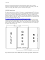
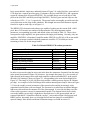
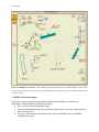
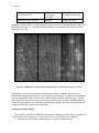
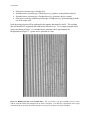
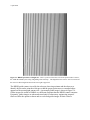
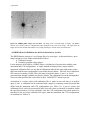
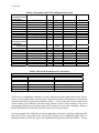
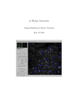
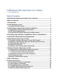
7 April 2006
HIRES Instrument and Data Format
1.0 HIRES Instrument
HIRES, the High Resolution Echelle Spectrograph, is installed permanently at the right
Nasmyth focus of the Keck-1 telescope, and was commissioned in the summer-fall of 1993. The
capabilities and functionality of the instrument are well described in Vogt et al (1994) and the
HIRES User's Manual. The instrument has arguably been the most powerful high-resolution
optical spectrograph ever built. It has been used in a wide range of astronomical studies. These
include investigations into the large scale structure and history of the universe through
absorption of high-Z quasar spectra; the structure and chemical evolution of stars and the related
evolution of galaxies; the chemistry and dynamics of solar system bodies; and the discovery of
hundreds of extra-solar planets through precise time-series analysis of small doppler motions of
such planets around their parent stars.
The instrument has achieved outstanding results partly through its high opto-mechanical stability
and long well-serviced continuity of operation. HIRES was designed to be versatile through the
optical spectrum covering 300 - 1000 nm by use of interchangeable optical components
optimized for either blue or red sides of the bandpass, in conjunction with a wide degree of
control of the imaged spectrum by the user. The interchangeable large optics include the
collimating mirrors and cross disperser grating mosaic. The cross-dispersers are changed out
between blue and red-blazed grating mosaics by observatory personnel for specific scheduled
research programs. Through an exacting calibration procedure the opto-mechanical position of
the cross-dispersers is recovered, ensuring the long-term stability required of the spectrograph.
HIRES is highly user-configurable through the remote operation of motorized stages to select
spectral and spatial resolution, filter bandpasses, grating settings to position wavelength regions
of interest precisely on the CCD, and focus settings of optics and the CCD to achieve high data
quality. It is also supplied with internal calibration sources and supplemental instrumentation
including the iodine cell velocity reference, sky position image rotator, and photon-counting
exposure meter.
1.1 The Upgraded HIRES CCD Mosaic
On 18 August 2004, HIRES underwent a major upgrade of its detector. The CCD upgrade
resulted in significant improvements in the HIRES detector, dewar, and CCD electronics. The
new detector consists of a mosaic of three 2048 x 4096 15-μm pixel MIT/Lincoln Labs CCDs,
compared to a single 2048 x 2048 24-μm pixel Textronix CCD of the old detector. The new
device has dramatically: 1) improved the blue/UV response shortward of 3800 Å (by a factor of
~ 8), 2) increased the wavelength coverage for single instrument setting, 3) provided finer
sampling of the point-spread function (PSF), and 4) reduced the CCD readout noise and readout
time. New software was developed and old software enhanced to handle the new electronics and
higher data density. In addition, a new field flattener was created to accommodate the increased
7 April 2006
mosaic size and the flat focal plane characteristics of the new CCDs. Table 1.0 below shows a
comparison of the CCD characteristics between the two devices. Other, most up-to-date
characteristics of the detector mosaic can be found at
http://www2.keck.hawaii.edu/inst/hires/usernotes.pdf.
Table 1.0: Comparison of CCD characteristics
Old CCD
Manufacturer
Array size
Pixel size
QE (@ 3200 Å)
CTE
Dark current
Readout noise
Readout time
Textronix
One 2048 x 2048
24 μm
8%
< 10 e /pixel/hour
5-6 eSeveral minutes
Upgraded CCDs
MIT/Lincoln Labs
Three 2048 x 4096
15 μm
65%
0.999997
2 e-/pixel/hour
< 3 e< 30 sec.
The figure below shows the layout of the new CCD mosaic compared to the old system, and how
it is situated in the dewar and oriented with respect to the spectral orientation.
The gaps between the CCD chips are about 100 μm (6-7 pixels).
Figure 1.0: Layout of the new HIRES upgraded CCD mosaic
7 April 2006
At the focus of the spectrograph camera, the CCD detector is held at -130 C operating
temperature continuously through the use of an automated liquid nitrogen filling system. The
CCD focus is highly stable and has required re-calibration infrequently.
2.0 HIRES Image Format
The data produced by the new HIRES CCD mosaic are in multiple-extension FITS file format.
This consists of a primary header, which is the first header of the FITS file, followed normally
by three or more extensions, called header data units (HDUs). Each HDU contains the two
standard components of any FITS file: (a) an ASCII text header holding a list of keywords that
describe the data unit of that HDU, and (b) the binary data following it. For a description of the
keywords in the primary header unit, visit
http://www2.keck.hawaii.edu/koa/public/keywords/koa_keywords.php.
The number of extensions is determined in part by the number of amplifiers used, and can be
controlled by the PANE and PANELIST keywords. In normal operations, single-amp readout
would produce three extentions (HDUs), one for each CCD in the mosaic. In dual-amp readout
mode, the number of HDUs would double to six. A schematic of the data mosaic in the singleamp mode is shown in Figure 2.0.
Figure 2.0 Schematic layout of the three HIRES CCDs in their default, single-amplifier, unbinned format.
7 April 2006
In its current default, single-amp, unbinned format of Figure 2.0, each of the blue, green and red
CCD chips has a separate prescan region 12 columns wide (keyword PRECOL), and a postscan
region 80 columns wide (keyword POSTPIX). The available image area of each chip is 2048
pixels wide (NAXIS1) and 4096 pixels high (NAXIS2). The blue, green and red chips are also
referred to as CCD = 1, 2 or 3, respectively. The spectral orders run roughly up and down in the
vertical direction on the chips in this schematic. Wavelength increases from bottom to top and
from left to right on each chip, as in Figure 1.0.
The HIRES CCD electronics and software are capable of reading out the current 2048 x 4096
pixel, three-CCD mosaic in a number of different modes. The most important readout
parameters, corresponding keywords, and default values are listed in Table 2.0. These values
correspond to single-amplifier, low-gain readout with single pixel binning. Currently, only one
amplifier, SINGLE:B, is functional. Amplifier modes SINGLE:A or DUAL:A+B are not usable
at this time. An image recorded with these parameters would be 52,761,600 bytes in size
(assuming a fixed size for the image header).
Table 2.0: Default HIRES CCD readout parameters
Readout parameter
Number of readout amplifiers
Number of video inputs
Pixel binning factor
Number of prescan columns
Number of postscan columns
CCD readout amplifier gain
Mosaic readout mode
CCD readout speed
Keyword
AMPMODE
NVIDINP
BINNING
PRECOL
POSTPIX
CCDGAIN
MOSMODE
CCDSPEED
Default value
SINGLE:B
3
1,1
12
80
low
B, G, R
fast
In order to increase the signal to noise ratio in the data, the astronomer frequently bins the image
in the spatial (horizontal in Figure 2.0) direction. An example bias image (e.g. zero second, no
light exposed on the image) taken with single-amplifier readout and binned by 2 in the spatial
direction (2x1 binning) is shown in Figure 2.1, corresponding to the same layout displayed in
Figure 2.0. This image is 26,461,440 bytes long and has a smaller postscan region (40 columns
per chip). An example of a flat field image taken with an internal quartz lamp is shown in Figure
2.2. Note the roughly vertical orientation of the spectral orders and the increasingly wider
separations between them with wavelength. The spectrum is recorded from an internal halogen
light source directed into the entrance slit of the spectrograph. It is used by dividing out of the
science object spectra to correct for instrumental response. The diagonal streak [most clearly
seen in the middle (green) chip] is light that is dispersed twice by the spectrograph, and is a
scattered light defect. Sometimes called the “meteor”, such scattered light is not present in all
HIRES spectra, but mainly shows up in bright flat field and star images at certain HIRES
spectral settings. More details on internal calibration images are found in section 3.1.
7 April 2006
Figure 2.1 HIRES bias image in its 2x1 binning format. Orientation is as in Figs. 1.0 and 2.0
Figure 2.2 HIRES flat field image in its 2x1 binning format. Orientation as in Figs. 1.0 and 2.0
7 April 2006
3. HIRES Configurations and Image Types
The HIRES is very broadly configurable through its user interface which controls the
selection and positions of instrumental components through remote operation of motorized
stages. The HIRES user interface is shown in Figure 3.0. The user interface provides a
schematic of the instrument light path, a status display with broadcasts of the current position of
each motorized stage, and individual and compound control of the motorized stages through popup menus and a multitasking utility (called GO). Components which form a basic HIRES
instrumental configuration include:
• Slit or decker size
• Wheels behind the slit filter (2 each 12 position)
• Collimator selection, including focus, which is accomplished through a look-up table
• Echelle grating position
• Cross-disperser type
• Cross-disperser grating position
Table 3.0 lists keywords which describe the above configuration parameters.
Table 3.0: HIRES Instrumental Configuration Parameters
Configuration
parameter
Slit decker
Keyword
DECKNAME
Filter wheel 1 selection
Filter wheel 2 selection
Collimator
Echelle position
Cross-disperser type
Cross-disperser position
LFIL1NAME
LFIL2NAME
COLLBLUE or COLLRED
ECHRAW and ECHANGL
XDISPERS
XDRAW and XDANGL
Possible values
30 (ascii, configurable but generally
fixed)
12 (same)
12 (same)
blue (not blue), red (not red)
integer and real
BLUE, RED
integer and real
7 April 2006
Figure 3.0: HIRES user interface. Each motorized stage of the instrument is controlled through a menu which
pops up when the stage button is selected. The current position of each stage and cover is broadcast to the interface
every few seconds.
3.1 HIRES Calibration Images
Calibration images are defined as data taken with internal illumination or without any
illumination. Standard internal calibrations include:
• Bias: zero-second non-illuminated image
• Dark: non-illuminated images taken at longer exposure times to measure dark current in
the CCD electronics
• Flat field: spectra taken with internal quartz halogen illumination for each HIRES
configuration setting
7 April 2006
•
•
•
Thorium-Argon (Th-Ar): spectra taken with the Th-Ar lamp in each HIRES configuration
setting
Trace: spectra taken with the D5 pinhole with internal quartz illumination to provide a
trace spectrum for echelle order extraction. This purpose is often fulfilled with standard
stars or the program stars if sufficiently bright.
Focus: Th-Ar spectra taken with D5 pinhole for focusing purposes
Non-illuminated calibration images include short-exposure (i.e. generally less than 2s) or zerolength exposure bias images, and long exposure dark images. Table 3.1 lists keywords that may
be used to identify bias and dark images. Keywords listed with more than a single possible value
might only be used to verify an image type (for instance, if AUTOSHUT is F then the shutter did
not open and the resulting image is a bias or dark; a similar discussion holds for other keywords
in Table 3.1). Dark images are not frequently taken, since the CCD system has very low dark
current that is inconsequential for all reasonable exposure times. Still, a dark image can be used
as a system diagnostic at any time and should be part of a long- term instrument trend analysis.
Table 3.1: Internal calibration keywords: bias or dark image
Internal calibration identifier
Bias image, shutter
Bias image, exposure length
Dark image, shutter
Dark image, exposure length
Bias or dark image
Keyword
AUTOSHUT
TIME
AUTOSHUT
ELAPTIME
HATCLOS
Value
F
Short (< 2) s
T or F
Any value
closed or not closed
HIRES is equipped with internal calibration lamps that project halogen flat field and ThoriumArgon comparison sources onto the entrance slit. The flat field spectrum is used to correct
scientific object spectra for pixel to pixel variation in CCD response, and in some cases to
correct for instrumental wavelength response. An example of a flat field spectrum is shown in
Figure 2.2. The Th-Ar spectrum provides emission lines at precise wavelengths, the positions of
which are used to wavelength calibrate the science object spectra. An example a Th-Ar
spectrum is shown in Figure 3.1. Table 3.2 lists keyword values that can be used to identify
images as internal calibration spectra of certain types.
Table 3.2: HIRES internal calibration keywords
Internal calibration identifier
Keyword
Flatfield spectrum
LAMPNAME
Trace
Focus
DECKNAME
DECKNAME
LAMPNAME
DECKNAME
LAMPNAME
Value
quartz, quartz1 or quartz2
(ascii)
Same as program object
D5
quartz, quartz1 or quartz2
(ascii)
D5
ThAr1 or ThAr2 (ascii)
7 April 2006
Th-Ar spectrum
Th-Ar spectrum ON
Comparison mirror in beam
LAMPNAME
CATCUR1 or
CATCUR2
LMIRRIN
ThAr1 or ThAr2 (ascii)
25.0 (real, nominal, mA)
in light path (ascii)
Note that LAMPNAME is a configurable keyword, so there is no guarantee that the values will
match those in Table 3.2. For ThAr spectra, the lamp current must also be turned on for the
spectrum to be valid.
Figure 3.1: HIRES Th-Ar comparison spectrum binned 2x1. Orientation as in Figs. 1.0 and 2.0
Other images used for data calibration include spectra taken of standard stars or the sky
background. Standard stars fall into several categories, including flux standards, flat continuum
stars for atmospheric telluric line removal, radial velocity standards, and other types. Bright
stars are also used to provide a trace spectrum for echelle order extraction. Sky background or
direct reflectance spectra are often taken in planetary programs to provide a solar spectrum for
subtraction from the scientific object spectrum.
3.2 Program Object Images
The scientific versatility of HIRES means that the instrument is used to observe a number of
classes of objects by astronomers. These include but are not limited to the following:
• Point-source spectroscopy of faint objects (e.g. quasars and faint stars).
7 April 2006
•
•
•
•
Point-source spectroscopy of bright stars.
Extended-source spectroscopy of faint objects (e.g. galaxies, some planetary objects)
Extended-source spectroscopy of bright objects (e.g. planetary objects, comets)
Point-source velocity-calibrated spectroscopy of bright stars (e.g. planet-hunting with the
use of the iodine cell).
Each observing program will be conducted in the manner determined by the PI. The resulting
data will therefore be organized and calibrated in different ways. Two example program object
spectra are shown in Figure 3.2 (extended object spectrum with a superimposed sky
background) and Figure 3.3 (point source spectrum of a star).
Figure 3.2: HIRES spectrum of an extended object. This is a portion of the green (middle) CCD of a comet
with the reflected and absorbed sunlight from the earth’s atmosphere. The dark lines superimposed on the bright
continuum bands are primarily Fraunhofer absorption from specific elements in the Sun's atmosphere.
7 April 2006
Figure 3.3: HIRES spectrum of a bright star. This is a portion of the blue CCD. Each spectral order is narrow,
the width determined by the seeing and guiding of the telescope. The diagonal streak “meteor” can be seen toward
the lower left. Wavelength increases from lower right to upper left.
The HIRES guider camera is used by the telescope observing assistant and the observer to
identify objects and to point the telescope so that the proper point source or extended object
appears on the spectrograph entrance slit. An example guider image is shown in Figure 3.4.
Guider images are stored at WMKO on a different computer than the HIRES control computer.
Frequently, guider images are taken and stored only for observatory engineering purposes.
Observers have the option to choose and save selected guider images for their own use.
7 April 2006
Figure 3.4: HIRES guider image of a star field. The image scale is inverted (black is bright). The HIRES
entrance slit is faintly evident as a brighter horizontal rectangle in the center of the image. The signal from the
bright star left of the slit has saturated the CCD, causing the charge to "bleed" in the vertical direction.
4.0 HIRES Data Set Definition for the Keck Observatory Archive
The HIRES dataset consists of a set of image files of several types. As discussed above, these
image categories can be further subdivided as follows:
1. Calibration images
2. Scientific (program) object images
For the purposes of the archive, a HIRES dataset is defined as all spectra taken with the same
instrument and CCD configurations. A simple method of linking science targets with the
appropriate calibration files is to say that all calibrations taken on the same night as the science
target and with the same configuration is part of that objects dataset. The basic set of calibration
files consist of a number of flats, ThAr (arc lamp), bias and/or darks. A “trace” or “focus”
spectrum taken through a pinhole may also be present. The calibration files can be distinguished
from each other and from the science files by their “IMAGETYP” header keyword.
Association of a science object with calibration files is made in near real time as an archive
query is sent. A calibration can be associated with a target by comparing certain keywords that
define both the instrument and CCD configurations (see Table 4.1). A pair of science and
calibration files is said to be associated if these keyword values are identical or matched, within
the specified tolerances. For bias and darks, only the CCD configuration keywords need to be
matched; for the rest of the calibration file types, both the instrument and CCD configurations
are matched (see Table 4.2).
7 April 2006
Table 4.1 Instrument and CCD Configuration Keywords
INSTRUMENT
CONFIGURATION
KEYWORDS
SLITWID
SLITWIDT
FIL1NAME
FIL2NAME
COLLRED
COLLBLUE
ECHANGL
XDISPERS
XDANGL
CCD
CONFIGURATION
KEYWORDS
AMPMODE
AMPLIST
BINNING
MOSMODE
NVIDINP
PRECOL
POSTPIX
CCDGAIN
WINDOW
CCDSPEED
DESCRIPTION
UNIT
FORMAT
EXAMPLES
Slit width
Slit width projected on sky
Filter #1
Filter #2
Red collimator in?
Blue collimator in ?
Echelle angle
Cross disperser type
Cross disperser angle
mm
arcsec
deg
deg
float
F10.8
A8
A8
A1
A1
F9.8
A4
F9.8
10.21383190
0.861
KV370
clear
T/F
T/F
0.01441866
RED
0.32800001
Amplifier mode
Amplifier list
Binning
Mosaic readout mode
No. of video inputs
Pre-column pixels
Post-column pixels
CCD gain setting
CCD window
CCD readout speed
-
char
SINGLE:B
pix
pix
pix
-
char
I1,I1
char
I1
I3
I3
char
A25
char
3,1,0,0
2,1
B, G, R
3
12
80
low
0,0,0,2048,2048
fast
TOLERANCE
±0.005
±0.005
±0.001
±0.001
±0
±0
Table 4.2 Keywords Comparison for Association
Science Files
Object
IMAGETYP
Calibration Files
CCD Comparison Only
Both Instrument and CCD Comparison
Bias
Flatlamp
Dark
Trace
Arclamp
Focus
The best set of calibrations is defined to be those taken on the same night as the science files or,
if they’re not available, those closest in time. Currently the archive user interface is constraint to
automatically look for associated calibrations within +/- 3 days of the date of observations of the
science targets. All calibration files that match with the science files according to the above
prescription within the specified date range will be returned. An ascii file containing a listing of
all the calibration files associated with each science file is also provided.
In future upgrades, the calibration association algorithm will look for matching calibration files
taken only on the same night as the science files, moving out to neighboring nights only if a
minimum number of files for each of the calibration file types has not been reached. If users
7 April 2006
desire to search for calibration files over more extended time periods, this option will also be
implemented.
References:
HIRES User’s Manual, http://www2.keck.hawaii.edu/inst/hires/manual1.pdf
Vogt et al. (1994), "HIRES: the High Resolution Echelle spectrometer on the Keck
10-m Telescope," S.P.I.E., 2198, 362.