1
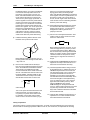
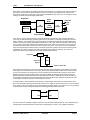
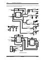
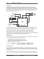
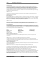
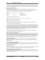
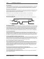
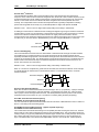
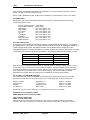
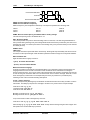
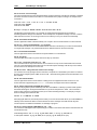
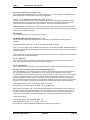
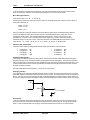
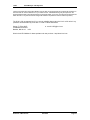
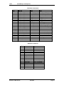
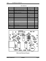
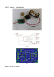
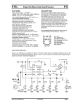
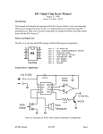
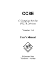
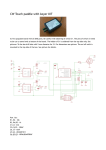
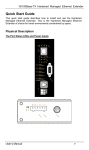
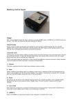
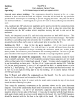
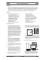
K1EL
K-20
CW Keyer and Keyboard Kit
Introduction
The K20 is a single board Morse keyer with a built in IBM AT keyboard interface. It can be used as a
keyer only or as a CW keyboard. All keyer configuration and control is done through the keyboard. This
is a kit product consisting of a single sided PCB, two PIC microcontrollers, memory, board-mounted
components, and keyboard connector. Through hole components are used allowing easy assembly.
This document describes how the K20 works, how to assemble one, and how to operate it.
Features
•
•
•
•
•
•
•
•
•
•
•
•
•
•
•
•
•
•
•
•
•
•
Built-In PS/2 AT Keyboard Interface
Iambic CW Paddle Interface
PTT Output: Open Collector (low true)
Adjustable lead in and tail delays
Key Output: Open Collector (low true)
Adjustable Speed 5-99 WPM
Adjustable Dit/Dah Weighting
Adjustable Character Spacing
Built-In Sidetone Generator
On Board Speaker
Sidetone with adjustable frequency
12 Message memories
No crystals or oscillators
Operating Voltage: 8-18 VDC
On board regulated 5 volt supply
Current Draw: < 5 ma less keyboard
Embedded commands in messages
Iambic A, B, and “Bug” keyer modes
Built in CW practice modes
Autospace
First Dit/Dah adjustable correction
HSCW Output Capability
Assembly Instructions
First off, inventory and identify all parts
ahead of time using the Bill of Materials on
Page 18. This will allow the assembly to
proceed smoothly. You might want to verify
resistor values with an ohmmeter if your
color impaired like I am.
1
3)
First install C5. Then the 1/4 watt resistors.
It's best to start with R1 and do them in
order. (Note that R3 and R7 are not included
in the kit) Double check the silk screen to
make sure you are putting them in the
correct holes. After soldering, trim the leads.
Red
7805
7)
Bend a resistor lead scrap to fit in the JMP
position and solder it in place.
K20 User’s Manual rev2
Install the three bypass caps C4, C8, C9.
Blk
After inventory, carefully inspect the PCB for
any solder shorts between etches, it's easier
to find one now.
8
locate pin one later on. It's easier if you bend two
legs over on the back to hold them in when you
solder them in place. If you do this just make sure
that the bent over lead doesn't accidentally short
to an adjacent trace.
6)
2)
4)
Next install the three 8 pin DIP sockets. Orient
them so the little notch in the top aligns with the
notch in the silk screen. This will make it easier to
G
1)
5)
8/27/2003
B+
The assembly of the K20 is very easy; all
you need is a low wattage soldering iron,
some solder, a few pieces of hook up wire, a
pair of decent wire cutters, and small pliers.
A VoltOhmMeter is handy for debug but not
essential if you take your time and assemble
the kit carefully. You will also need some
sort of power supply that provides a voltage
between 8 to 18 VDC (12VDC is optimum) at
about 250 ma. These instructions will take
you through a step by step process that will
test portions as you go. This will make
debugging much easier since if a problem
arises you will be able to locate the source
right away.
Now we will install and check out the 5-volt
regulator circuit. First ins tall C1 and C2
followed by VR1. The long lead of C2 goes
toward R1 (plus). Orient VR1 as shown in
Page 1
K1EL
K20 CW Keyer and Keyboard
the diagram above, if you put it in backwards
it won't work. Next strip and tin the end of
two pieces of hook up wire: one red, one
black, and install the black wire as shown in
the G hole and the red wire in the B+ hole.
These are our power supply input leads. To
test the regulator connect the power leads to
a power source that can provide something
in the range of 7 to 18 volts DC. Connect the
red lead to the positive power terminal and
black to the negative. Turn on the power and
measure the voltage between pin 1 and 8 on
U1 with a voltmeter. Pin 1 should sit at +5
volts relative to pin 8, if it doesn't recheck
that VR1 is in correctly and there aren't any
solder shorts. Remove power after testing.
8)
Install Q3 observing that the flat face of the
transistor lines up with the silk screen.
Next install the speaker, make sure you put
the long speaker lead through the hole with a
+ sign next to it.
9)
Now it's time to install and test the Keyer
PIC. First of all, install two lengths of hook up
wire in the PCB holes marked DAH and DIT.
These will be your paddle keying leads.
Connect a third wire to the G hole next to the
AF hole. This will be the common return from
the keyer paddles. Carefully install U1 (the
12C672 PIC with the red dot) in the socket
with the little circular notch on the IC and
1
U1
socket lining up:
Turn on the power and the K20 should come
to life and send an "R" out the speaker. If
not, quickly turn power off and recheck the
IC orientation. If that's OK, look for solder
shorts on the IC connections. When you get
that to go, touch the keying leads to the
keying ground lead you should get dits,
dahs, and alternating dits/dahs if you hold all
three together. If there is a problem here, the
first place to check is for correct values in
R1, R2, and R5. Again solder shorts are the
most common source of assembly problems.
Remove power after testing.
10) Now install the keying transistor Q1 and the
PTT transistor Q2. Also install the keying
bypass caps C3 and C7, you may have to
straighten the leads to get them to fit
properly in the PCB.
11) We are now at the keyboard interface. First
install L1 and L2, these consist of a ferrite
bead on a resistor lead:
Next, install the keyboard connector J1, the
holes are a tight fit but if you take your time
you'll find it will slide into place. Make sure
the connector body is flush against the PCB
before you solder it in place. Now install the
12C672 Console PIC U2 (white or no dot)
observing pin 1 alignment as was done in
step 8.
12) Install the 24LC16B EEPROM U3 observing
alignment as in step 8. Note that all ICs on
the boards are oriented the same way.
13) Test the keyboard interface: Plug in a PS/2
style keyboard into J1. (Please don't use an
old IBM-XT keyboard as it won't work and
may damage the K20). Turn on power and
you'll hear the KEYER PIC send an "R"
followed by an "N" (which means the K20
has detected a brand new EEPROM). At the
same time the lights on the keyboard may
come on and then go out, in any case the
lights should be off after power up. Now
press the NUMLOCK key and the
NUMLOCK light on the keyboard should
come on. Press it again and it'll go out. Press
any letter key and it should come out the
Keyer PIC in sidetone with the PTT and KEY
lines activated as well.
14) That's it! After reading through the theory of
operations it’s on to the command section
learn about the K20 command set.
Theory of Operation
This section will help you learn how the K20 works. As shown in the block diagram two PIC processors
share the task of converting keystrokes to Morse code. U2, the console PIC, is responsible for retrieving
K-20 User’s Manual rev2
8/27/2003
Page 2
K1EL
K20 CW Keyer and Keyboard
keystrokes from the keyboard and determining what to do with them. U1 is the Keyer PIC which is a slave to
the console, its main task is to generate Morse code and monitor the keyer paddle inputs. It throttles the
Console PIC via the flow control signal. The 2-kilobyte EEPROM memory stores up to 12 messages, system
settings, and holds the keyboard type ahead buffer.
Keyboard
EEPROM
Memory
Serial
Data
U2
Console
Flow
Control
Transmit:
Key
U1
Keyer
PTT
AF
Keyer Paddle
There are two types of keyboard inputs: Commands and Data. Commands modify the K20's operation in
some way, for example changing operating speed, turning off sidetone, recording a message etc. Data are
letters, numbers, or prosigns that are to be sent in Morse. Commands and data are processed differently in
the K20. Data is put into a type ahead buffer that allows the user to type faster than the Morse that is being
sent. The size of this buffer is about 200 characters and is a FIFO which is an acronym for First In First Out.
This means that characters are taken out in the order they were put in. Since there can be a considerable
delay from keyboard input to Morse output, commands bypass the input FIFO and are sent to the Keyer PIC
immediately. This allows changes to be made immediately while sending is underway. The command
bypass also allows one message to be sent while another is being entered.
Key
Processor
Key Input
Command
Bypass
FIFO
Output to Keyer PIC
Since there are times when you don't want commands to take effect immediately, the K20 allows commands
to be buffered. This means that the command is placed in the typeahead buffer and won’t be acted on until it
comes out of the buffer. An example of the use of a buffered command would be to send two words at two
different speeds, the first at 15 WPM and the second at 20 WPM. By placing a buffered speed command
between the words the speed will not be changed until the first word is completely sent. Not all, but many of
the immediate commands can be entered as buffered commands. Most often, buffered commands are used
in messages. This will be covered in the message entry section.
The K20 provides a low-level filtered “near sinewave” sidetone audio output which can be fed into the microphone of a transmitter. By keying the transmitter with the PTT output you have AF driven CW. The PTT output is
open collector and in most cases can drive the transmitter PTT input directly. Full control over PTT is provided to
compensate for transmit changeover delay and hold keying between letters and words.
MIC
AF
PTT
PTT In
Transceiver
K20
One of the Keyer PIC’s analog to digital converters is used to read the paddle input. R1, R2, and R5 make up a
voltage divider network that feeds a voltage to the PIC depending on which, if any, paddles are pressed.
K-20 User’s Manual rev2
8/27/2003
Page 3
K1EL
K20 CW Keyer and Keyboard
The K20 also has a built in speaker driver that can drive either an on board Piezo speaker or an external 8-ohm
speaker. The volume is fixed by an on board resistor.
R1 - 4.7KΩ
C4
.01 µF
DAH
5 VDC
R2
10KΩ
1
2
3
4
Serial
Data
Vcc
Gnd
PTT
Paddle
Key
FlowCtl
6
Tone
Serial In
C5
.001 µF
R5 - 10KΩ
DIT
8
G
7
6
Flow Ctl
R7 - 330KΩ
R3 - 33KΩ
AF
5
C10
.05 µF
U1 - Keyer
PIC12C72
JMP
C6
.05 µF
5 VDC
SPKR
R8 - 100Ω
Q3
2N2222
1
B+
C1
.047 µF
VR1
7805-5.0V
Regulator
KEY
3
5 VDC
+
2
SPK
R6 - 4.7KΩ
C2
47 µF
C7
.01 µF
Q2
2N2222A
G
PTT
R4 - 4.7KΩ
C8
5 VDC
1
2
Serial Data
FlowCtl
Q1
2N2222A
.01 µF
Vcc
Gnd
Kclk
EEPclk
8
C9
7
6 6
3 SerOut EEPdata
4 FlowCtl
5
Kdata
U2 - Console
PIC12C72
1
2
J1
3
PS/2 4
Keybd 5
6
C3
.01 µF
L2
1
2
A0
A1
3 A2
4
Gnd
.01 µF
Vcc
8
5 VDC
WP 7
6
SCL 6
SDA
5
U3 - EEPROM
24LC16B
5 VDC
L1
K20 PCB Schematic
K-20 User’s Manual rev2
8/27/2003
Page 4
K1EL
K20 CW Keyer and Keyboard
Using the K20
The following diagram illustrates a basic K20 set up. The paddle is optional and is not a requirement.
Likewise the K20 could be used without the keyboard but it would not be possible to enter commands, or
play messages. The PTT output is used primarily in HSCW and AF keying modes. A PTT connection would
not be required for normal CW keying of a transmitter or transceiver. The on-board keying circuit on the K20
PCB is only capable of keying positive voltages up to 60 VDC. It is not compatible with negative keying
voltages and external circuitry is required.
Iambic
Paddle
GND
8-18 VDC
To XMIT Key Input
V+ G
PTT
G
DAH
KEY
K20
DIT
AF
G
SP
To PS/2
Keyboard
K1EL K20 PCB
The sidetone SP output can drive an 8-ohm speaker in a situation where you need more sidetone volume.
The 100-ohm resistor R8 fixes the volume level and can be adjusted to suit. In most configurations you will
use the sidetone built into your transceiver, but it’s nice to have it for practice or testing purposes.
When the K20 powers up it will automatically load its settings from EEPROM and be ready to use.
Messages will be preserved from your last session as well as any setting you may have saved.
!! Important Note: Some older keyboards draw a significant amount of power and can cause the 7805
regulator to overheat. A heatsink maybe required in some extreme cases !!
Shift/ALT/CTL Keys
This is basic stuff but, the Shift, Ctrl, and Alt keys allow multiple key functions to be assigned to a single key.
If you are not familiar with these keys here’s how they are used:
1) Press and hold the CTL key then press the letter A for CTL-A.
2) Press and hold the ALT key then press the letter A for ALT-A.
3) Press and hold the SHIFT key then press the letter A for SHIFT-A.
4) Press the A key by itself for the letter A
In this User Manual: SHIFT-key
ALT-key
^key
refers to a key pressed with Shift: SHIFT-F1 for example
refers to a key pressed with Alt:
ALT-PGUP for example
refers to a key pressed with Ctrl: ^C, ^B for example
General Information
The K20 accepts input from a keyboard or iambic paddle; you can switch between them whenever you want.
Just remember if there is data being sent out of the circular buffer when you press the paddles, the two may
collide and give you unexpected results. If you want to pause the K20 in order to use the paddles just press
the Insert or TAB key.
When you press a command key that requires additional parameters, the CAPS light on the keyboard will
turn on to remind you that more keystrokes are required to finish the command. When recording a message
K-20 User’s Manual rev2
8/27/2003
Page 5
K1EL
K20 CW Keyer and Keyboard
or other stored information the CAPS light will stay on until recording is ended. When the K20 is in pause
state (via the INSERT/TAB KEY or by the ^W buffered wait command) the CAPS light will flash to remind
you the K20 is paused and waiting for user intervention (either a INSERT or TAB key) to continue. The
SCROLL LOCK light is used to signify when either a message buffer or the type ahead buffer is full. Most of
the information on how to use the keyer revolves around the command set so we will dive right in.
Command Description by Key
Note: SHIFT-F1 means F1 pressed while the shift key is held. For clarity a space is placed between
commands and values in the following examples, in reality no spaces are used in any command. Likewise
argument values shown enclosed with <> are entered without the <>. So an example like:
SHIFT-F2 <45> should really be entered as SHIFT-F245
F1 through F12: Send Message
To make message access easy, they are assigned to the twelve function keys. Hitting one of these keys will
cause a message to be queued up and sent after the current contents of the FIFO buffer have been sent, in
other words they are buffered commands. There is no way to send a message immediately except to clear
the FIFO buffer with the ESC key and then send the message. If you hit the message key of an empty slot
nothing will happen. See the SHIFT-F1 command description below for instructions on how to load a
message.
SHIFT-F1: Save Something in Memory
The K20 has the ability to store messages and other items in non-volatile memory. Non-volatile means that
the memory contents are preserved even if power is turned off. Recording begins by pressing the SHIFT-F1
key; the following chart shows all available recording options:
SHIFT-F1 followed by:
F1-F12
SHIFT F9-F12
SHIFT 0-9
M
P
- Record a message
- Set a Fast WPM key
- Record a Custom Prosign
- Map a numeric
- Store current settings as the power-on default
Message Recording
Message recording is easy, let's say you want to put a new message in slot F4, first press SHIFT-F1 then
press F4. The CAPS light will come on to let you know that you are in record mode and you can then enter
your message. If you make a mistake you can back up using the BACKSPACE key. At any time you can
clear what you've done and start over by pressing the ESC key. Any alphanumeric key or prosign can be put
into a message as well as any buffered command. The message slots are fixed in size, when you get to
within 8 entries of the slot being full the SCROLL LOCK light will turn on. When you reach the end of the slot
(Slot FULL) the SCROLL LOCK light will flash. When you are all finished and want to save the message,
press the ENTER key and the CAPS LOCK light will go out. If you want to review your message, without
actually sending it, hit the Transmit Mute key (SHIFT-F7) followed by the desired message key and your
message will be played in sidetone only. (Don't forget to turn off transmit mute when you are ready to go
"live" again). The following chart shows the sizes of the 12 message buffers in letters/commands:
F1 - 200
F2 - 200
F3 - 200
F4 - 200
F5 - 200
F6 - 200
F7 - 200
F8 - 200
F9 - 42
F10 - 42
F11 - 42
F12 - 42
Fast WPM Keys
Four command keys SHIFT-F9 through SHIFT-F12 are assigned as Fast WPM change keys. You can
program these keys to speeds of your choice. To set these keys simply press SHIFT-F1 followed by the
desired Fast WPM key and a two digit number from 5-99. For example, to set the SHIFT-F10 key to 14
WPM enter the sequence:
SHIFT-F1 SHIFT-F10 <14>
NOTE: Fast WPM settings are not automatically saved in EEPROM, to save them you need to enter the
“Preserve Settings” command (SHIFT-F1 P) described in a later section.
K-20 User’s Manual rev2
8/27/2003
Page 6
K1EL
K20 CW Keyer and Keyboard
Custom Prosigns
You can permanently assign 10 custom prosigns. A "prosign" in this context is simply any two normal
characters concatenated into a single character. The 10 abbreviation keys !@#$%^&*() are reserved for
custom prosigns. Several common prosigns such as AR, SK, BT, And DN are already assigned (see page
15) so you don't have to add these. One application of this feature could be adding special European
language characters or uncommon prosigns. To illustrate how the command works let's assign AS to the @
key, just enter the following sequence:
SHIFT-F1 @ A S
From this time on, anytime you press @ AS will be sent. Custom prosigns are automatically stored in
EEPROM after they are entered.
Numeric Mapping
Numeric Mapping allows you to substitute a letter for a number when sending a serial number. T is a popular
mapping for zero but you can choose what you like for 0 and any other numbers 1-9. To record a mapping
press SHIFT-F1 followed by M. After the CAPS light turns on, press the number you want to map followed
by what you want it to map to. So to map 0 to T you enter the sequence:
SHIFT-F1 M 0 T
NOTE: Only 0 through 9 can be mapped. Numeric mappings are not automatically saved in EEPROM, to
save them you need to enter the “Preserve Settings command (SHIFT-F1 P) described below.
Preserving Settings
The basic settings of the K20 are preserved when power is shut off. When the K20 is powered on for the first
time a default set of values are loaded into EEPROM. You can customize these defaults very easily. When
you have the K20 setup the way you like it, just press SHIFT-F1 followed by the letter P and current settings
for the following items will be saved in EEPROM memory:
Speed
Weight
Character Spacing
Iambic Mode
Autospace Setting
Paddle Swap
Sidetone disable
Sidetone Frequency
PTT delays
Serial number
Paddle Sensitivity
Fast WPM keys
Numeric mapping
SHIFT-F2: Change Sending Speed
This immediate command will set the current WPM speed to whatever you desire. The syntax for the
command is:
SHIFT-F2 <nn>
where nn is a two digit decimal speed from 05 to 99 WPM
Two digits must be entered or the command will be ignored. Note that you can also change speed in
increments of 1 WPM with the UP and DOWN arrow keys. See the section on buffered commands to learn
how buffered speed changes are made.
SHIFT-F3: HSCW Speed Set
The K20 supports HSCW (High Speed CW) transmit rates through the use of this immediate command. The
syntax for the command is :
SHIFT-F3 <nn> where nn is a two digit number representing the lpm rate divided by 100.
For example nn=20 selects 2000 lpm and nn=35 selects 3500 lpm. Any rate from 1000 to 8000 can be
picked although only a handful are actually used by radio amateurs. In the US, common rates are 1000,
2000, 4000 and 6000 lpm while in Europe 1000, 1500, 3000, 4000 lpm are common.
HSCW Operation Hints: In running HSCW mode, a common practice is to key the transmitter when
sending and feed keyed audio tones into the microphone input. You can use the K20 sidetone output directly
as a tone source as this is a keyed 2000 Hz tone in HSCW mode. Alternatively, you can use the K20 key
output to key an external tone generator. In either case, the PTT output of the K20 should be connected to
the PTT input of the transmitter.
K-20 User’s Manual rev2
8/27/2003
Page 7
K1EL
K20 CW Keyer and Keyboard
You have a choice of either inserting an HSCW command at the beginning of every message or use the
SHIFT-F3 command to force the K20 into HSCW mode at all times. Use SHIFT-F2 to leave HSCW mode by
setting a non-HSCW CW speed.
SHIFT-F4: Morse Code Practice
A dual mode multi-level code practice program is built into the K20. It's accessed via the SHIFT-F4
command key. There are two styles of practice, receive only and echo (receive/respond) practice. There are
four levels of practice organized by easy to difficult letter groups. The four levels are:
Level 1:
Level 2:
Level 3:
Level 4:
E
C
1
?
T
Q
2
/
A
P
3
,
N
J
4
.
I M W
F B V
5 6 7
AR SK
S G D U K O R
Y H X Z L
including level 1
8 9 0
including level 1 & 2
BT AS
including level 1 & 2 & 3
The syntax for entering a practice mode is:
SHIFT-F4<style><level> where style is R for receive or E for echo practice
SHIFT-F4 R2 selects Level 2 receive practice
SHIFT-F4 E4 selects Level 4 echo practice
Receive Practice Description: Random characters from the selected level are sent in groups of five.
Practice will continue until the ESC key is pressed.
Echo Receive/Transmit Practice Description: The K20 will send a character from the selected level and you
must respond by echoing the character back on the keyboard. If you get it right the K20 will repeat the first
character followed by a new character. Now you must echo back both characters. The K20 will continue to
add characters until it reaches five after which it will start with a new set. If you miss a character the K20 will
send 8 dits and start over with a new sequence of characters. When you want to end this practice hit the
ESC key and the K20 will send an SK to let you know it’s done.
Known Bug: If you hit a message key during Echo practice the K20 will send random characters for the
length of the message and then go back to echo practice.
SHIFT-F5: Toggle Farnsworth Sending
Farnsworth spacing is useful for CW practice because it encourages you to learn characters by sound not
individual dits and dahs. In the K20, Farnsworth is implemented by sending letters at a fixed rate of 18 WPM
regardless what the WPM sending rate is. Spacing between characters is determined by the sending rate.
When the WPM rate is set above 18 WPM, Farnsworth is automatically disabled. It's a "toggle" command
which means if Farnsworth is on when you press SHIFT-F5 it'll be turned off, if it's off you'll turn it on
SHIFT-F6: Toggle Sidetone
This is how you turn sidetone on and off. If you would rather use the sidetone already provided by your
transceiver just disable the K20 sidetone, it's not required. This command is both an immediate and a
toggle command.
SHIFT-F7: Toggle Transmitter Muting
This command allows you to temporarily disable the Key and PTT outputs. Sidetone is not affected by this
command. Transmit muting is useful for verifying a message "off line" or for code practice. This is both an
immediate and toggle command.
SHIFT-F8: Tune Toggle
Use this command to force transmit keying to a constant key down condition. Both the KEY and PTT outputs
are turned on. Press SHIFT-F8 again to cancel tune. ESC will also cancel a tune command.
SHIFT-F9 through SHIFT-F12: Fast WPM Keys
In contesting or just general QSO hunting it's handy to have several preset CW speed settings that you can
select with a single key press. One key press and your speed gets changed. You learned how to program
these keys in the SHIFT-F1 section.
K-20 User’s Manual rev2
8/27/2003
Page 8
K1EL
K20 CW Keyer and Keyboard
ALT Commands
The ALT command keys are configuration commands that setup K20 operating preferences. In most cases
you'll set these once, save them to memory, and not think about them again. Remember to use the SHIFTF1 P command to save these settings in EEPROM so that they will be loaded next time you power up.
ALT-F2: PTT Lead In Delay Time
The K20 provides a transmitter PTT output that can be used to switch a transmitter over to transmit mode in
advance of actual CW keying. You have control over the time delay between when PTT is asserted and
when CW keying will start. The format for the command is:
ALT-F2 <nn>
where nn is a two digit number calling out the delay in 10's of milliseconds.
nn= 26 selects 260 milliseconds. The maximum delay that can be set is 99 or 9.9 seconds.
ALT-F3: PTT Tail Delay Time
The time of PTT deassertion is programmed in units of 10 of mSecs. The syntax is the same as ALT-F2.
PTT
Lead-in Delay
Tail Delay
Key
The letter A
ALT-F4: Set Serial Number
For contesting, the ability to send and keep track of a serial number is indispensable. This command allows
you to preset the serial number to any 4 digit number from 0000 to 9999. Just hit ALT-F4, wait for the CAPS
LOCK to light and enter 4 numbers. If you make a mistake hit ESC to cancel and re-enter the number (in
other words backspace won’t work on this guy). Any non-numeric entered will cause the K20 to simply
ignore the command and not change the serial number. Once the serial number is set you can increment,
decrement, and send the serial number using buffered commands CTL-I, CTL-D, and CTL-N respectively.
ALT-F5: Toggle Softsidetone
There are two sidetone modes, standard and soft. The K20 sidetone output is a squarewave toggling
between 0 and 5 volts. In standard mode the sidetone output rests at zero volts between tones. In soft mode
the sidetone output pin is tristated at rest. This helps reduce the hard sound of the sidetone. Note that this
only applies to AF keying it shouldn’t be enabled if the onboard speaker and AF driver transistor are used.
ALT-F6: Toggle BUG Mode (applies to paddle input only)
The K20 supports Iambic A, B and Bug manual keying modes. In iambic mode the K20 makes both dits and
dahs automatically based on which paddle you press. In bug mode the K20 makes the dits and you make
the dahs. You also can use bug mode to operate in straight key mode or if you want to key through the K20
with a different keyer, simply set bug mode and use the dah input to key the K20.
ALT-F7: Toggle Autospace (applies to paddle input only)
Here is how autospace works: If you pause for more than one dit time between a dit or dah the K20 will
interpret this as a letter-space and will not send the next dit or dah until full letter-space time has been met.
The normal letter-space is 3 dit spaces but by using the ALT-LEFT and ALT-RIGHT commands you can
modify this. The K20 has a paddle event memory so that you can enter dits or dahs during the inter-letter
space and the K20 will send them as they were entered. With a little practice, autospace will help you to
send near perfect Morse.
ALT-F8: Toggle Iambic Mode between A and B (applies to paddle input only)
In either iambic mode, alternating dits and dahs are sent while both paddles are held closed. In mode B an
extra alternate dit or dah is sent after both paddles are released.
ALT-F9: Swap Paddles (applies to paddle input only)
You can swap paddles with the command. This is a nice feature to have when right and left handed ops
want to share the same keyer.
K-20 User’s Manual rev2
8/27/2003
Page 9
K1EL
K20 CW Keyer and Keyboard
ALT-F10: Set 1 st Extension
The K20 addresses problems often encountered when keying older transceivers with slow break in
response. Due to a slow receive to transmit changeover time, the first dit or dah of a letter sequence can be
chopped and reduced in length. Adding a fixed amount to the first element of a sequence can compensate
this for. In other words if an R is sent the first dit will be elongated but the subsequent dah-dit is sent
normally. The compensation amount is transceiver dependent and is generally independent of sending
speed. Note though that this is usually only a noticeable problem at higher CW speeds >25 WPM.
ALT-F10 <nn>
where nn is a two digit number (0-99) calling out the delay in milliseconds.
A challenge in this scheme is to determine when sending has stopped long enough to cause the transceiver
to switch back to receive. If it has it’ll require a new first element correction on the next sequence. The K20
uses the PTT tail timer to determine this, set the tail timer to roughly match the transmit to receive
changeover time of the transceiver and things will work fine. It takes some trial and error to get it set up right
so make sure you save the values in EEPROM when you're done using the SHIFT-F1 P command.
Normal R
Increased 1st Dit
ALT-F11: Set Weighting
This command allows a fixed amount to be either added or subtracted from the length of all dits and dahs
sent. QSK keying on modern transceivers can cause shortening of the dit and dah elements which is
especially noticeable at high speeds. The K20 allows the length of the dit and dah elements to be increased
uniformly to compensate for this. The dit/dah lengths can also be decreased as well. The adjustments are
made in units of one millisecond steps. The maximum adjustment is 49 mSecs and the minimum is –50
mesas. The format for the commands is:
ALT-F11 <nn>
where nn is a two digit number calling out the delay in milliseconds.
When nn = 50 there is no adjustment, greater than 50 are adds, less than 50 are subtracts. So for example,
nn=48 will subtract two mSecs while nn=52 will add two mSecs. nn=99 will add 49 mSecs, nn=00 will
subtract 50 mSecs.
Decreased Weighting
Normal R
Increased Weighting
ALT-F12: Start Persistent Beacon
When this command is issued the K20 will send the message in slot 1 (F1) repetitively. A jump to message
F1 command is not required at the end of the message. The message can contain any valid command,
calls or jumps to other messages will be honored. It is called persistent because if power is lost and then
restored the beacon will continue to cycle. The beacon is ended by hitting the ESC (escape key).
ALT-LEFT: Decrease Intercharacter Spacing
ALT-RIGHT: Increase Intercharacter Spacing
You can customize the space between characters with this command. It adds/subtracts in units of 10ths of a
dit time. This setting will track sending speed.
ALT-PGDN: Decrease Paddle Sensitivity (applies to paddle input only)
ALT-PGUP: Increase Paddle Sensitivity
This controls when the K20 will start looking for a new paddle press after sensing the current one. The K20
doesn’t wait for a dit or dah to finish before looking for the next paddle action. This means there needs to be
a delay to allow you to get off a paddle before it’s latched again. If there were no delay the keyer would send
dits or dahs continually, if there is too much delay it bogs you down because you can't get ahead of the
keyer. The default value is one dit time and is adjustable in units of 1/10th of a dit time. Faster operators
K-20 User’s Manual rev2
8/27/2003
Page 10
K1EL
K20 CW Keyer and Keyboard
report a setting somewhat less than default is more pleasing. Use the ALT-HOME command to check the
setting. The delay is calculated with this formula:
DELAY_TIME = (SENSITIVITY*DIT_TIME)/10 where Sensitivity is a value between 5 and 33, 10 is default
ALT-HOME: Status
Hitting this key will cause several status values to be sent in Morse. Hitting ESC will abort the sending.
The following values are sent:
Console Software Revision
Keyer Software Revision
WPM Setting
Ratio Setting
PTT Lead In
PTT Tail
1st bit Adjust
Weighting
Extra Letterspace
Paddle Sensitivity
(single letter)
(single letter)
(one or two digits 5 – 99)
(one or two digits 5 – 33)
(one or two digits 0 – 99)
(one or two digits 0 – 99)
(one or two digits 0 – 99)
(one or two digits 0 – 99)
(one or two digits 5 – 33)
(one or two digits 5 – 33)
ALT-TAB: A/D Diagnostic
A diagnostic tool is provided to help debug problems with the paddle analog interface. The paddles
are connected to the Keyer PIC's via a built in analog to digital converter. By reading the voltage on a
resistor voltage divider circuit, the paddle’s position can be determined by comparison to predetermined thresholds. To allow for tolerance in resistor values and connection paths there is a range
of values that will meet each of the four possibilities. The following table gives the ranges for each:
Paddle State
Both paddles up
Dit paddle down
Dah paddle down
Both paddle down
Keyer Pin 7 Voltage
5 - 3 volts
2.9 – 2.0 volts
1.9 – 1.4 volts
1.39 – 0 volts
A/D Diag Callout
> 152
151 – 104
103 – 71
70 - 0
When the ALT-F12 command is issued the K20 will continually send the A/D input value in decimal. You can
look the value up in the chart to check out your paddle connections. Sometimes paddle contacts can exhibit
unusually high resistance values due to corrosion, this can cause the K20 to incorrectly respond to a paddle
press. Most times a good cleaning of the contacts will fix things up. Be careful to follow your paddle
manufacturer’s recommendation for contact cleaning as abrasives can damage contact plating.
CTL-ALT-DEL: Clear EEPROM and Restart
This causes the K20 to clear all of EEPROM and reload the factory settings. Be careful when using this
because it will erase all of your messages, prosigns, and numeric mappings. The factory settings are:
Speed = 15 WPM
Autospace off
Iambic B
PTT Delays = 0
Extra Space = 0
1st Extension = 0
Weighting normal
Ratio normal
Shift-F9 = 13 WPM
Shift-F10 = 15 WPM
Shift-F11 = 18 WPM
Shift-F12 = 20 WPM
Known bug: only one of the two delete keys on the keyboard will work for CTL-ALT-DEL
UP ARROW: Increase Speed by 1 WPM
DOWN ARROW: Decrease Speed by 1 WPM
LEFT: Decrease Dit/Dah Ratio
RIGHT: Increase Dit/Dah Ratio
Add or Subtract 10% of a dit time from the dah time. This causes an intentional distortion of the Morse
waveform. Some ops use this option to make their CW sound less “machine like”. A little goes a long way !!
K-20 User’s Manual rev2
8/27/2003
Page 11
K1EL
K20 CW Keyer and Keyboard
Increased Dit \Dah Ratio
Normal R
Decreased Dit \Dah Ratio
PGUP: Increase Sidetone Frequency
PGDN: Decrease Sidetone Frequency
Sidetone frequency can be adjusted in fixed steps. The steps are specified in the following chart:
400 Hz
444 Hz
500 Hz
571 Hz
666 Hz
800 Hz
1000 Hz
1333 Hz
2000 Hz
HOME: Reset Character Spacing and Dit/Dah Ratio to factory settings.
This sets extra spacing to zero and dit/dah ratio to 1:3
ESC: Abort/Clear Buffer
This can be pressed at any time to abort a message, abort a command, or to clear the typeahead buffer. If
this is pressed during message entry the message buffer will be cleared and you effectively can start over at
the beginning. (Note: You need to press enter to exit message entry, ESC just clears what you have entered
and starts you over)
INSERT: Pause
TAB: Pause
You can put the K20 into pause with either of these keys. Sending will stop immediately and will not resume
until Insert or Tab is pressed again. While the K20 is paused the CAPS Lock light on the keyboard will flash.
DEL: Send Error Dits
Eight dits will be sent to signify a CW error.
+ (plus): Increment Serial Number
- (minus): Decrement Serial Number
Buffered Command Language
A simple yet powerful command set is provided that allows you to assemble complex CW messages. The
language revolves around 13 basic commands. These commands can be inserted into a message to
perform various functions. They occupy space in the message slot so be careful in using them when the slot
is close to being full. Review the SHIFT-F1 command to learn how to record a message. When F1 or some
other message key is referred to in the examples this just means you press the F1 (or whatever) key.
Following is a list of the commands including descriptions:
F1-F12 - Jump to message
As mentioned previously message keys are buffered commands which are sent as they are taken out of the
FIFO buffer. The ability to jump from one message to another is very useful. Here’s a simple example:
Load Slot F1 with: CQ CQ F3
Load Slot F2 with: QRZ QRZ F3
Load Slot F3 with: DE K1EL K
Message F1 will be sent as: CQ CQ DE K1EL K
Message F2 will be sent as: QRZ QRZ DE K1EL K
Jump can be used to make a message loop, here how:
Load Slot F1 with: CQ CQ CQ CQ DE K1EL K1EL K1EL F1
After sending CQ CQ CQ CQ DE K1EL K1EL K1EL we loop back to the beginning and send it again. This
will repeat forever until the ESC key is pressed.
K-20 User’s Manual rev2
8/27/2003
Page 12
K1EL
K20 CW Keyer and Keyboard
CTL-C <F1 -F12> - Call a message
The call command will jump to the specified message, send that message, and after the message completes
the stream will return to where it was called. It is more flexible than a jump to message. An example of this
command is:
Load slot F1 with: ^C F2 ^C F2 de ^C F3 ^C F3 BTU OM KN
Load slot F2 with: WA1ABC
Load Slot F3 with: K1EL
Message F1 will play as: WA1ABC WA1ABC DE K1EL K1EL BTU OM KN
This illustrates a powerful feature; you can build up complicated messages that can be reused by
substituting different callsigns in a called slot. In this example the complicated message is in slot F1 and the
called slots are F2 and F3. Even though F2 and F3 are called by F1 they can still be sent individually.
CTL-D - Decrement Serial Number
The four digit serial number is decremented by one. If equal to zero the serial number is not decremented.
CTL-H <nn> - Change to HSCW mode, nn = (lpm/100)
This command acts the same as the immediate HSCW command. This allows you to insert an HSCW burst
in a regular CW message or to put HSCW bursts of two different rates into the same message.
CTL-I - Increment Serial Number
The four digit serial number is incremented. If equal to 9999 it is not incremented.
CTL-K - Key down
The transmitter will be held in key down state until a Key Up command.
CTL-L <nn> - Load Loop Count (nn = 01 → 99)
This command works in conjunction with the CTL-Z command. A loop count is entered with this command.
The CTL-Z command will decrement this loop count and will repeat a message until the loop count reaches
zero. See the CTL-Z description for more info.
CTL-M <C1><C2> - Merge Next Two Letters into a Prosign
You can build "on the fly" prosigns with this command. Just press CTL-M followed by two letters or numbers
and they will be merged together: ^MAR is sent as AR. Note that nothing will be sent until both letters have
been entered.
CTL-N - Send Serial Number
The four digit serial number is sent in Morse. Leading zeros are suppressed so 0047 is sent as 47. If a
number has been mapped using the SHIFT-F1 M command, the mapped value will be substituted.
CTL-P - Pause Output Until Insert/TAB Key Pressed
K20 output keying will be paused indefinitely until either the INSERT or TAB key is pressed. While paused
the CAPS LOCK light on the keyboard will flash to let you know that pause is in effect. This command is
used to insert a pause into a message to allow you to insert something manually. For example you might
make a message up that looks like this:
UR RST IS ^P NAME HR IS STEVE
After playing UR RST IS, the K20 will pause to allow you to enter an RST after which you hit the INSERT or
TAB key which releases the K20 to continue with the rest of the message. Note that the ESC key also
cancels a pause, but will kill the remainder of a message in progress.
CTL-S <nn> Change Speed to NN WPM (nn = 05 → 99)
You can build a message that has a speed change in it with this command. Note that this command also will
cancel HSCW mode.
Load Message Slot F1 with: ^S 10 CQ CQ DE K1EL K1EL ^S 22 CQ CQ DE K1EL F1
F1 will repeat until ESC: CQ CQ DE K1EL (at 10 wpm) CQ CQ DE K1EL (at 22 wpm)
K-20 User’s Manual rev2
8/27/2003
Page 13
K1EL
K20 CW Keyer and Keyboard
CTL-T <nn> Load Timer (nn = count 0 → 99)
This command when used with the CTL-W command allows you to enter a repeating message that has a
fixed repeat length and a fixed pause time. Here’s an illustration:
In Slot F1: ^T 60 WA1XYZ WA1XYZ DE K1EL K1EL ^W 40 F1
The CTL-T command specifies an interval for which the body of the message will be repeated. Until that
interval expires the CTL-W command will be ignored. Once the CTL-T interval does expire the K20 will
pause for the interval specified by the CTL-W command. So the above message will result in:
“WA1XYZ WA1XYZ DE K1EL K1EL” being repeated over and over for 60 seconds after which there will
be a pause of 40 seconds after which it loops back and repeats. ESC will stop the message. This command
is very useful for HSCW exchanges.
CTL-U Key Up
This command cancels the CTL-K (key down) command.
CTL-W <NN> Wait for NN Seconds (NN = 01 → 99)
This command is used to insert a fixed pause into a message, it’s well suited for building a beacon
message:
Load Message Slot F1 with: VVV ^K ^W 05 ^U BCON DE K1EL ^P 60 F1
When you press F1 three V's will be followed by a keydown for 5 seconds, then BCON DE K1EL will be sent
followed by a pause of 60 seconds after which the whole thing will be repeated. This beacon will repeat until
you hit the ESC key.
Longer delays than 99 seconds can be derived by looping a wait command in a DECSZ loop. (an example is
given in the CTL-Z command description).
CTL-X – Assert PTT
This command is used to override PTT control and assert it manually. It will stay asserted until a CTL-X.
When PTT is asserted the open collector PTT output is pulled low.
CTL-Y – Deassert PTT
This command is used to override PTT control and deassert it manually. It will stay asserted until a CTL-X.
CTL-Z <F1 -F12> Decrement Loop Count and Skip Message if Zero
This command allows you to control looping in a message. The structure of the command consists of the
CTL-Z command followed by a message key (F1-F12). There must be a load loop command in the
message stream somewhere ahead of the CTL-Z command. When the CTL-Z command is encountered the
loop count is decremented by one and if the result is not zero the message is jumped to. If it is zero the
message is skipped. The first time the ^L command is encountered the count is loaded and subsequent
CTL-L commands are ignored until the loop count expires, this allows a loop count load and loop count test
to reside in one message. The best way to describe the command further is with a couple of examples:
Load Message Slot F1 with: ^L 02 CQ CQ DE K1EL ^Z F1 SK
Results when F1 is pressed: CQ CQ DE K1EL CQ CQ DE K1EL SK
What happens is this; When CTL-L is processed the K20 loads the count and stores it, then it outputs the
message. The CTL-Z command tells the K20 to decrement the loop count and test to see if it is zero, if it
isn’t zero the K20 jumps back to the beginning of F1, If however the count is zero the K20 skips over the
jump and just outputs the SK. Remember that the CTL-L command is ignored after the initial load.
Longer delay example:
Load Message Slot F1 with: BCON DE K1EL F3
Load Message Slot F3 with: ^L 10 ^W 60 ^Z F3 F1
Results when F1 is pressed: BCON DE K1EL will be repeated every 10 minutes
K-20 User’s Manual rev2
8/27/2003
Page 14
K1EL
K20 CW Keyer and Keyboard
In this example the message is sent followed by a jump to F3 which waits for 60 seconds 10 times (which
gives us 10 minutes). After the 10 minute wait we jump back to F1 and do it all over again.
More Message Examples:
Load F5 with: Count is ^N. ^D ^W 05 F5
Assuming the serial number has been preset to 100 the F5 message will be sent in sequence with a delay of
5 seconds in between as:
Count is 100.
Count is 99.
...
Count is 0.
Here’s an example of a beacon setup that runs at two different power levels. It assumes that the K20 PTT
output controls the transmitter power output, when PTT is deasserted we select 1 watt, when PTT is
asserted we select 5 watts. The message below first deasserts PTT, sends 1 watt then keys the
transmitter for 5 seconds. Then it unkeys the transmitter, asserts PTT, sends 5 watts then keys the
transmitter again for 5 seconds. Then it unkeys the transmitter, sends DE K1EL and loops back to repeat.
Load F3 with: ^Y 1 watt ^K ^W 05 ^U ^X 5 watts ^K ^W 05 ^U DE K1EL F3
Additional Key Assignments
There are several other key assignments that are treated just like letters and are buffered.
=
<
>
[
is mapped to
is mapped to
is mapped to
is mapped to
BT
AR
SK
QRZ
]
/
;
‘
is mapped to
is mapped to
is mapped to
is mapped to
QSL
DN
KN
AS
High Speed CW Operation
The K20 supports HSCW operation by being able to send character strings at 200 WPM speeds and higher.
HSCW is primarily used to work other stations by using Meteor Scatter propagation. The method of operation
calls for short bursts of characters to be sent repetitively at high speeds for a predetermined period of time. The
receiving station listens and records the sporadically received bursts and plays them back at a slow speed to
decipher the Morse message.
See http://www.nitehawk.com/rasmit/ws1_15.html for more information.
AF Keying Interface
The K20 PCB has an onboard audio filter/attenuator used to convert the square wave sidetone into a low level
sinusoidal output that is suitable to feed into a transmitter’s mic input. The values listed in the bill of materials for
R3, R7, C6, C10, produce a level of approximately 5 millivolts depending on load impedance. Other values can
be chosen to either increase of decrease the level or a potentiometer can be used to allow an exact level control.
AF
K20 PCB
100 K
0 ↔ 5 mVolts
RF Immunity
There are several RF filter points included in the K20 circuit design. Caps C3 and C7 on the keying and PTT
lines prevent RF from coming back through the keying lines while C5 shunts any RF arriving over the paddle
leads. L1 and L2 attenuate RF from coming in on the keyboard data and clock lines to the Console PIC.
K-20 User’s Manual rev2
8/27/2003
Page 15
K1EL
K20 CW Keyer and Keyboard
These components also reduce RF radiation from the K20. Some keyboards can produce RF emissions on
their own that can cause interference on your radio receiver. Additional filtering may be required on the
keyboard itself usually a large ferrite bead on the keyboard cable. (post note: most keyboards manufactured
within the last 5 or 6 years must meet stringent RF radiation requirements and are seldom a problem).
The K-20 is fully guaranteed and if you are not satisfied please return the kit for a full refund. Any
questions will be handled by snail-mail or e-mail via these addresses:
Steven T. Elliott K1EL
43 Meadowcrest Drive
Bedford, NH 03110
USA
or e-mail: [email protected]
Watch the K1EL Website for latest updates and new products: http://www.k1el.com
K-20 User’s Manual rev2
8/27/2003
Page 16
K1EL
K20 CW Keyer and Keyboard
Immediate Commands
Key
F1
F2
F3
F4
F5
F6
F7
F8
F9
F10
F11
F12
↑ UP
↓ DOWN
← LEFT
→ RIGHT
PGUP
PGDN
HOME
TAB
ESC
INSERT
Normal
Play Message 1
Play Message 2
Play Message 3
Play Message 4
Play Message 5
Play Message 6
Play Message 7
Play Message 8
Play Message 9
Play Message 10
Play Message 11
Play Message 12
Speed +1 WPM
Speed –1 WPM
Dit/Dah Ratio–10%
Dit/Dah Ratio+10%
Sidetone Higher
Sidetone Lower
Reset Weight/Space
Pause Transmit
Abort
Pause Transmit
Shift
Record
Set WPM Speed
Set HSCW Rate
CW Practice
Toggle Farnsworth
Toggle Sidetone
Toggle XMIT Mute
Toggle Tune
Quick Speed 1
Quick Speed 2
Quick Speed 3
Quick Speed 4
N/A
N/A
N/A
N/A
N/A
N/A
N/A
N/A
N/A
N/A
ALT
N/A (not assigned)
Set Lead-in Delay
Set Tail Delay
Set Serial Number
Toggle Soft Sidetone
Toggle Bug Mode
Toggle Autospace
Toggle Iambic A/B
Swap Paddles
st
Adjust 1 Bit Length
Adjust Weighting
Persistent Message
N/A
N/A
Reduce Letterspace
Increase Letterspace
Increase Sensitivity
Reduce Sensitivity
Status
A/D Diagnostic
N/A
N/A
Buffered Commands
CTL
C
D
H
I
K
L
M
N
P
S
W
T
U
X
Y
Z
K-20 User’s Manual rev2
Command
Call Message
Serial # -1
Set HSCW
Serial #+1
Key Down
Load Loop Count
Merge Letters
Play Serial#
Pause
Set Speed
Wait
Load Timer
Key Up
PTT On
PTT Off
DECSZ Loop
Syntax
^CF1
^D
^Hnn nn=lpm/100
^I
^K
^Lnn nn=count
^MAR
^N
^P
^Snn nn=wpm
^Wnn nn=seconds
^Tnn nn=seconds
^U
^X
^Y
^Z
8/27/2003
Page 17
K1EL
K20 CW Keyer and Keyboard
Bill of Materials
Reference
K20PCB
U1
U2
U3
VR1
Q1, Q2, Q3
J1
R2, R5
R3
R1, R4, R6
R7
R8
C1
C2
C3, C7, C4,
C8, C9
C5
C6, C10
L1, L2
SPKR
JMP
U1, U2, U3
Description
K20 Printed Circuit Card
PIC12C672 Keyer(Red Dot)
PIC12C672 Console(No Dot)
24LC16B EEPROM
LM7805 5 volt Regulator
2N2222A transistor
PS/2 Keyboard connector
10 KΩ Resistor
33 KΩ Resistor (optional)
4.7 KΩ Resistor
330 KΩ Resistor (optional)
100 Ω Resistor
.047 capacitor
47 µf capacitor
.01 µf 100 VDC capacitor
Package
PC Board
8 Pin DIP
8 Pin DIP
8 Pin DIP
TO220
TO92
6 PIN DIN
1/4 W
1/4 W
1/4 W
1/4 W
1/4 W
ceramic disc
electrolytic
ceramic disc
.001 µF capacitor
.047 µF capacitor (optional)
Ferrite bead
Piezo Speaker
Jumper
Sockets
ceramic disc
Check
axial lead
resistor lead
8P DIP socket
Silkscreen Reference Diagram
K-20 User’s Manual rev2
8/27/2003
Page 18