1
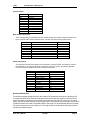
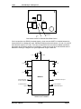
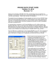
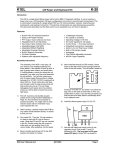
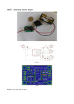
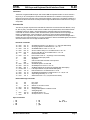
K1EL
CW Keyer and Keyboard Serial Interface Guide
K-20
Introduction
The K20 is a single board Morse keyer with a built in IBM AT keyboard interface. It can be used as a
keyer only or as a CW keyboard. This document will describe how to interface to the asynchronous
serial port of the keyer and drive it from a personal computer or other host. The interface is based on a
simple set of ASCII commands. The K20 provides a single handshake line that tells when it is ready to
accept data.
Command Set
The K20 only accepts asynchronous serial data at 1200 baud. The format must be 8 data bits, 1 stop
bit, with no parity. Note that the K20 must be modified to accept RS232 data, see the K20 hardware
modification section for details. Normal alphanumeric characters will be sent as Morse letters,
commands are control characters, which are listed below. Special characters such as prosigns are
listed in a separate table. When formatting a command no spaces should be added between
commands and/or arguments, also numeric values must always be sent as two decimal digits with a
leading zero if the value is less than 10. The only exceptions to this are the MODE register command in
which the value is sent as a two digit hexadecimal value.
Immediate Commands
^A
^B
^C
^D
^E
^F
^G
^H
^I
^J
^K
^L
^M
^N
^O
^P
^Q
^R
^S
01h
02h
03h
04h
05h
06h
<nn>
07h
08h
09h
0Ah
0Bh
<nn>
0Ch
<nn>
0Dh
<hh>
0Eh
<list> 0Fh
<nn>
10h
<nn>
11h
<nn>
12h
<tl>
13h
<nn>
<nn>
<nn>
<nn>
<nn>
nn
nn
nn
nn
nn
Set sidetone frequency to nn where nn = 4 – 0AH (see table below)
Set keying speed to nn WPM where nn = 05 - 99
Set Dit/Dah Ratio to nn/10 nn = 05 - 32
Set PTT Lead-In delay to nn*10 milliseconds nn = 00 - 99
Set PTT Tail delay to nn*10 milliseconds nn = 00 - 99
Pause transmit On/Off
nn
Flow Control Count 01 – 30 (change not recommended)
Backspace buffer input pointer
Say Status
Clear circular buffer and abort current process
Key Down on/off
nn
Set HSCW speed to nn*100 LPM
nn
Set Extraspace to nn/10 nn = 05 - 32
h
Set Mode Register to hex value hh (see Mode Reg. Description)
<….> Load Keyer Default List (see Defaults Description)
nn
First bit extension to nn milliseconds nn = 0-99
nn
Set Weighting Adjustment in milliseconds nn = 0 – 99, 50 = 00
nn
Adjust swing sensitivity nn = 0 - 99
tl
Start Practice t=e/r l=1,2,3,4 (see K20 User Guide)
Buffered Message Commands
^V
^W
^X
^Y
^Z
^\
^]
^^
<xy>
<nn>
<nn>
<nn>
16h
17h
18h
19h
1Ah
1Ch
1Dh
1Eh
nn
xy
nn
nn
nn
PTT on/off
Key on/off
Wait for nn seconds nn=0-99
Merge letters x,y
Change WPM speed to nn WPM nn=5-99
Analog diagnostic
Set HSCW speed to nn
Set loop timer to nn nn=0-99
Special Characters
/
:
<
BT
DN
KN
AR
K20 Serial Interface Guide
=
>
@
[
BT
SK
AS
QRZ
]
QSL
DEL 8 dits
10/10/00
Page 1
K1EL
K20 CW Keyer and Keyboard
Sidetone Values
Value
01h
02h
03h
04h
05h
06h
07h
08h
09h
0Ah
Frequency
4000 hz
2000 hz
1333 hz
1000 hz
800 hz
666 hz
571 hz
500
444 hz
400 hz
Mode Register Description
There is an eight-bit byte in the Keyer PIC that contains bit flags that control the operation modes of the
keyer. Each bit’s state controls a particular mode, following is a table showing the bit functions:
Bit
7 (MSB)
6
5
4
3
2
1
0 (LSB)
Function
Iambic A when = 1 Iambic B = 0
Farnsworth on when = 1
Bug Mode on when = 1
Softsidetone on when = 1
Swap paddles when = 1
Disable sidetone when = 1
Autospace On when = 1
Mute Transmit when = 1
Power Up State
0
0
0
0
0
0
0
0
Defaults Description
All of the Keyers internal state registers can be initialized in one block transfer. This feature is useful for
fast initialization or for changing the whole configuration of the keyer quickly. The following illustrates
how the command is issued and the order of control words loaded.
Byte #
0
1
2
3
4
5
6
7
8
9
10
Value
0Fh (command)
Mode Register Value
WPM Speed
Sidetone Value
Dit/Dah Ratio
Lead In time
Tail Time
st
1 Bit Extension
Weighting
Extra Space
Sample Adjust
Power On Default
N/A
00
15
05
10
00
00
00
50
10
10
Hardware Modification
The K20 was originally designed to have the Console PIC provide the serial input to the Keyer PIC.
To operate the K20 with an external serial data source the Console PIC must be removed from its
socket and wires are soldered to two unused hole positions on the K20 PCB. One wire is for serial
data to the K20 the other is a flow control (ready) output. These signals are connected to a host which
provides all control to the K20. The paddle inputs to the Keyer PIC are unaffected and work normally.
The host must monitor the flow control line, if it is high the host must wait till the K20 drops it before
sending any additional bytes.
K-20 User’s Manual
10/10/00
Page 2
K1EL
K20 CW Keyer and Keyboard
Keyer
U1
R6
C8
C9
C onsole
(remove)
U2
U3
T ransmit
Serial D ata
Input to
K20
F low C ontrol
Output to H ost
Connections to K20 For External Serial Data Control
If the host provides true RS232 formatted signals, a level converter MUST be installed between the
host and the K20 or damage will result. Standard RS232 levels transit between –12 and +12 volts DC
while the K20 expects 0 to 5 volts. There are several RS232 level converters available from Maxim
that supply all the interface details in one package. Typical ones to look at are the MAX232 and the
MAX203. Following is a diagram of a typical application using the MAX 232
1 uF
+5 V o lts
16
1
2
1 uF
1 uF
3
4
6
1 uF
1 uF
5
MAX 232
F ro m K 2 0 F lo w
C o n tro l O u tp u t
T o K 2 0 R e c e ive
In p u t
11
14
T o R S 2 3 2 C T S In p u t
12
13
10
8
F ro m R S 2 3 2
T ra n s m it O u tp u t
15
RS232 Level Translator
K-20 User’s Manual
10/10/00
Page 3