1
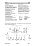
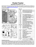
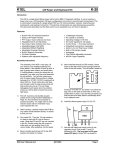
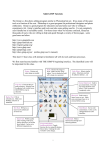
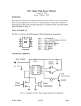
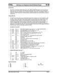
Building
and
Operating:
The PK-3
from Jackson Harbor Press
A PIC based keyer kit with pot speed control
General notes about building: The components should be inserted a few at a time,
soldered in place and then the leads are clipped. Note that all the leads for any particular
pad should be inserted prior to soldering to prevent clogging the holes. The pads and traces
are small and delicate - a small tipped, low power (25 watts or less) soldering iron should be
used.
Also, machined pin SIP sockets (not supplied) can be used to provide the connection points
to the off-board components, then the builder will be able to plug the wires from the
components into the SIP sockets which simplifies moving the unit in and out of the
enclosure.
Finally, the integrated circuit (IC) and the keying transistor are both MOS devices. This
means that they should be handled as little as possible to prevent static damage. The builder
should use a grounding strap and anti-static mat if available or at the very least, work on a
grounded metal surface and be sure to touch ground prior to touching the ICs.
Building the PK-3 - Step 1) Get the parts together: All of the board mounted
components have been supplied. You will still have to provide off-board items from the
stocklist to fully implement the keyer including the enclosure, speed pot, switch, jacks,
battery holder and connector, piezo transducer and mounting hardware. Be sure to get the
piezo transducer that requires external drive - basically a very high impedance speaker.
Step 2) Identify and orient the components: Most of the components should be fairly
easy to identify and place. The .01 uF monolithic ceramic bypass capacitors are very small
yellow or blue parts with 2 radial leads spaced .1" apart. You may need a magnifying glass
to see the markings on these parts. The four .01 uF bypass caps are marked 103. Note that
C6, the pot timing capacitor, is also a .01 uF capacitor but that it is reddish brown in color
and has a .2” lead spacing. U2, the 5V regulator, is laser marked and thus hard to read - try
to view U2 at an angle in strong light to see the marking. Q1 is clearly marked with the
2N7000 part number.
Step 3) Mount and solder the components on the board:
diagram for the placement and orientation of the parts.
Use the parts placement
Start by inserting the 8 pin IC socket with the small notch towards the top of the circuit
board and then soldering it in place.
Then insert the remaining components at the positions shown on the parts placement
diagram. Three of the components should only be inserted one way or they can be damaged
by reversed polarity. C2, the 47 uF electrolytic capacitor, should be inserted with the
negative stripe to the top side of the board. C2 can also be inserted with the leads bent at a
right angle which results in a lower overall height for the board. Q1, the 2N7000 transistor,
should be inserted with the flat face to the right of the board. U2, the LM2936 voltage
regulator, should be inserted with the flat face to the top of the board. Be sure to solder all
the connections and clip leads.
Step 4) Check your work: Before proceeding, take the time to check the bottom of the
board for solder bridges. Use the Bottom view diagram as a guide to visually check for
these shorts. It may help to clean the flux from the board and then use a strong light in
conjunction with a magnifying glass to see these problems. Also, double check the
orientation of the critical components such as the electrolytic capacitor, transistor and
voltage regulator. After you are convinced that the board is OK and after you have formed
the leads of the IC to fit in the sockets, insert the keyer IC into the socket, being sure to
follow the parts placement diagram for proper orientation. Now hook up the Piezo
transducer (beeper) to the connection points on the left side of the board (including a
connection to ground. Also solder the 9V battery snap to the top-left side of the board.
Next, power up the board. An FB should be sent by the keyer at powerup through the
sidetone if the keyer is functioning correctly. Note that you will only hear the FB if the
voltage across the 47 uF capacitor is fully discharged - since the keyer IC consumes less
than 10 uA of current in sleep mode it can take a long time before the capacitor is fully
discharged UNLESS a switch is pressed while the power is off. If you don’t hear the FB,
use a VOM to measure the current drawn. With a regulator, the idle current draw after
powerup at 9 V should be less than 10 uA. This will jump up to as much as 1.5 mA or so
when the keyer is active.
If you see significantly higher currents, power down immediately and check again for shorts
and/or opens. If the currents look reasonable, then power down and hook the unit up to the
switch, pot, paddle and output jack and proceed to the Operation section.
The kit has a micropower +5V regulator which allows a user to connect a 9V battery and
leave it connected without a power switch. The standby power drawn will be roughly 7 uA.
Active power is about 1.5 mA maximum with both paddle switches pressed - a MOSFET is
used as the output transistor and this minimizes the active current - also, the sidetone should
be connected to a piezo transducer which uses only 50 uA or so.
Construction Notes: If the keyer is to be packaged in the same case as the transceiver, it is
possible to inject the sidetone directly into the audio chain of the radio instead of using a
piezo transducer for the sidetone. The circuitry needed for this injection is a fairly simple
RC circuit to decrease the level of the sidetone from 5V peak to peak and also to filter the
square wave slightly (see the FREQ-Mite article in the December 1998 issue of QST OR the
Norcal 20 article in the Spring 1999 issue of QRPp for more details on this type of circuit). I
prefer to mount the keyer in a separate box so that it can be disconnected from the rig and
used for practice anywhere.
The keyer will fit into small metal boxes such as the old Sucrets boxes or the new, popular
Altoids mint tins. One possible problem area for this type of enclosure is finding a pot that
is small enough to fit. Mouser (800 346 6873) sells a 13 mm diameter, 100k pot (#
2
31CX501) that fits nicely into one of these types of tins. The small 4 mm shaft size of the
pot requires a special knob - Mouser also has these (# 45KN050).
If damaged, Q1, the 2N7000 MOSFET output transistor, can be directly replaced by the
more common 2N2222 or 2N3904 type NPN transistor. The orientation is the same,
however the NPN transistor will require more drive current than the 2N7000 MOSFET.
Note that the output transistor circuit is designed to switch key inputs of 13.8 volts positive
or less. Don’t attempt to use the PK-3 keyer with a vacuum tube transmitter (either grid
block or cathode keyed) without an appropriate outboard circuit - consult older ARRL
handbooks for these circuits. For negative keying voltages consider purchasing the Grid
Block Keying Adapter kit from Jackson Harbor Press.
The minimum pot speed will increase if the power supply voltage decreases below 5 volts.
Operation: General notes on using the switches to control the keyer: To give the keys
multiple functions, multiple key-press combinations are used. Also, the memory switch can
be pressed and released (PAR) OR pressed and held for two seconds (PAH). This also gives
more combinations of the three control switches (dit, dah and memory switch).
Generally, PAR is used for actions: send the code speed or send a memory. PAH is used for
settings: change the code speed (no pot) or record a memory or change the iambic mode.
4 menus are used for setting various options - they are activated by a PAH of the memory
switch alone or plus a simulpress of dit or dah or both. The menu selections are made by
pressing either the dit or dah levers - you will then normally hear a corresponding dit or dah
via the sidetone, the selection will be made and you are then returned back to normal keyer
mode. In general, the operator can skip a menu item by a PAR of the mem switch.
Note that the keyer sidetone will be higher in pitch (about 900 Hz) for keyer commands such
as the menu prompts, recording a memory or the FB sent at powerup. The normal pitch for
routine sending or practice is lower at about 600 hz.
A function table of the PK-3 keypress combinations:
keys used
PAR (press and release)
PAH (press and hold)
mem switch send mem 1
record mem 1 and beacon options
mem + dit
send speed or mem 3
paddle set of speed, pot options, record mem 3
mem + dah send CQ or callsign
Tune, record callsign & CQ options
mem + both send mem 2
record mem 2 and miscellaneous options
Powerup: Roughly one half second after powerup the keyer will send an FB through the
sidetone to signal correct operation.
Speed Readout: The speed (in WPM) will be played through the sidetone if the mem
switch is simulpressed with the dit lever and then both are released. I normally press the
memory switch first and hold it, press the dit lever and finally release both.
3
Speed Control and Menu: The speed can be adjusted by just turning the pot. Maximum
speed is 39 WPM, minimum speed is 5 WPM. Note that the minimum speed can be affected
by component tolerances on the timing capacitor and the speed pot - see the pot calibration
menu item if a 5 WPM minimum speed is required. The pot position is read continuously
when the keyer is sending code, just before each dit, dah or space is sent. This allows the
operator to adjust the code speed even in the middle of a memory send or record.
If you disconnect the pot from the circuit, the keyer will powerup at a default speed of 16
WPM. The speed can be adjusted by pressing and holding the memory switch along with
the dit lever. Usually I PAH the memory switch and then tap the dit lever. After 2 seconds,
the keyer will send an S (for speed set). Press the memory switch to advance to the next
menu item without changing the speed. Or, pressing the dit lever will increase the speed by
1 WPM and send a dit. Pressing the dah lever will decrease the speed by 1 WPM and send a
dah. You can continuously adjust the speed by holding either lever but note that if you run
the keyer “off the scale” at either 5 or 39 WPM, the keyer will “wrap around” to the
opposite speed extreme. Exit the speed adjust routine by pressing and releasing the memory
switch - the code speed will be sent via the sidetone upon exit.
Mem + dit menu (PAR mem to advance to the next menu item)
Menu item
pressing a dit:
pressing a dah:
S
Speed set from paddle
increases speed by 1 WPM
decreases speed by 1 WPM
P
Pot / paddle speed control selects pot speed control
selects
paddle
speed
control
C
Calibrate
pot
speed enters the calibration routine dah is ignored
control
RC Restore pot Calibration
restores
default
pot dah is ignored
calibration
T
Third Memory
selects the optional 3rd returns to 2 memories and
M
memory - O? is sent and then exits menu (default)
the third memory is recorded.
P - Select Pot or Paddle speed control: If the keyer is accidentally put into the paddle
speed control mode the pot speed control can be resumed by pressing dit.
C - Calibrating the Pot speed control: Due to the variation in capacitors and pots it is
possible that the maximum setting of the pot will result in a minimum speed higher than 5
WPM. This menu item will compensate and store an updated calibration value in RAM.
Before entering the menu, be sure to turn the pot to the minimum speed. Then press the dit
to go into the calibration routine - you then may hear one or more dits and the keyer will exit
from the menu.
RC - Restore the default pot Calibration: If the pot calibration is run with the pot
above midscale, the keyer may jump into paddle speed control if the pot is then turned below
mid-scale after calibration is complete. It won’t be possible to exit paddle speed control
4
because the calibration value is too low. This menu item will restore the default powerup
calibration value in RAM and thus allow normal pot speed control again.
TM - Third Memory (enable / record / disable): This option enables then records OR
disables an optional 3rd memory. Memory 2 is split into two 26 character memories. This
new third memory is then played with a mem+dit PAR simulpress. Record memory 3 in the
same fashion as the other 2 memories. The speed send is moved into the mem+dit menu as
the first item. Press either dit or dah to exit the mem + dit menu after the speed has been
sent.
Recording the Callsign Memory or using the Menu: A callsign of up to 10 characters
long can be recorded. This can be handy for things like: WB9KZY/BCN or WB9KZY/9 . The
callsign memory menu is entered by simulpressing the memory and the dah keys and
holding them for 2 seconds. I usually PAH the memory switch and then tap the dah key.
Mem + dah menu (PAR mem to advance to the next menu item)
Menu item
Pressing a dit:
Pressing a Dah
TU TUne mode
starts/ends key down
dah is ignored
?
Record
callsign records a dit
records a dah
memory
CS Callsign Select
selects a 3 x 3 CQ
selects a 4 x 2 CQ (default)
Q
/QRP after last callsign selects the /QRP option
deselects /QRP (default)
2
double the CQ send
doubles the CQ send
selects a single CQ (default)
N
No CQ
selects send of callsign only selects CQ+callsign (default)
TU - Tune mode: After 2 seconds the keyer will send TU. Press the dit lever to enter
tune mode (key down). Exit tune mode by a PAR of dit or dah.
? - Record the Callsign Memory: The callsign can now be recorded. When complete,
press the memory switch. The routine will be exited automatically after the 10th character is
sent. The callsign memory is saved in EEPROM - it will still be there even if power is
removed.
CS - CQ select: There are two different CQ sequences to select:
default (4x2)
optional (3x3)
CQ CQ CQ CQ DE <call> <c all> K
CQ CQ CQ DE <call> <call> <call> K
Press dit to select the 3x3 CQ or dah to select the 4x2 CQ. The keyer will send either a dit or
dah and then exit the menu. The <call> mentioned above is the callsign memory.
Q - /QRP after last callsign: This option will allow the operator to append a /QRP to the
last callsign sent - for example: CQ CQ CQ CQ DE WB9KZY WB9KZY/QRP K
Press dit to select the /QRP option, press dah to return to the default non-/QRP CQ. The
keyer will send either a dit or dah and then exit the menu.
5
2 - double the CQ send: This option will allow the operator to send two CQs in a row for example: CQ CQ CQ CQ DE WB9KZY WB9KZY CQ CQ CQ CQ DE WB9KZY WB9KZY K
N - No CQ send: This option will allow the operator to send just the callsign memory
with the mem + dah PAR combination. This is effectively a fourth memory for the keyer very handy for contests / pileups.
Playing the CQ + Callsign Memory: Play the CQ memory by simulpressing and releasing
the memory and the dah keys. I usually PAH the memory switch and then tap the dah lever
- the memory starts to play after the memory switch is released.
General notes on playing any of the memories: A tap of either the dit or dah lever will stop the
message play (except during the playing of /QRP). PAH the mem key during playback to pause the
message at the end of the play of the current character, you can then send manually with the paddles
and re-enter the message play with a PAR of the mem key. If the memory is empty an E will be sent
via the sidetone.
General notes on recording Mem 1 and 2: Note that you can insert the callsign memory at any
given point in the message by sending 6 dahs in a row. You can also insert a pause into the memory
by recording the AS (di-dah-di-di-dit) character. Message play will stop when an embedded pause is
reached - the paddle can then be used to send something manually - the message play can then be
resumed with a PAR of the mem key. This is useful for inserting an RST or a serial number into a
message. You can also embed a space of 6 dits in length by entering a special character of di-dahdah-dah-dit. Note that spaces do count as characters in the capacity of a memory. You can insert the
callsign memory, pause or space multiple times - each insertion takes up one character in memory.
Playing Mem 1: Play the memory with a PAR of the memory switch. The memory will start to play
right after the memory switch is released.
Recording Mem 1 and Menu: The Mem 1 menu can be entered by a PAH of the mem switch
(alone) for 2 seconds. After 2 seconds the keyer will enter the menu (you’ll hear a BE).
BE
M?
KD
BA
D
Mem switch menu (PAR mem to advance to the next menu item)
Menu item
pressing a dit:
pressing a dah:
BEacon mode
starts the beacon going
dah is ignored
Record Mem 1
records a dit
records a dah
Key Down beacon delay selects key down during the selects key up (default)
delay between memory during
delay
between
sends
memory sends
Beacon Alternate mode selects alternate beacon selects send of mem 1 only
sends of mem 1 and mem 2
(default)
increase the beacon increases delay by 1 second decreases delay by 1 second
Delay
BE - Beacon Mode: Beacon mode will send the contents of mem 1 continuously with a selectable
(see D below) pause in between each play of the memory. Start the beacon by pressing the dit lever the beacon starts to play. Exit beacon mode by tapping the dit or dah lever.
6
M? - Record Mem 1: Start sending your message. when complete, press the mem key. The
memory is 57 characters long - recording will terminate automatically after the 52nd character.
KD - Key Down beacon delay: Press dit to select the key down beacon delay mode. This will
enable the sending of a constant key down during the interval between sending the beacon message.
Press dah to return to the default key up beacon delay. The keyer will send either a dit or dah and
then exit the menu.
BA - Beacon Alternate between mem 1 and mem 2 mode: This routine selects/deselects
alternating the beacon between mem1 and mem 2.
D - increase the beacon delay: Normally, the beacon delay will be a single word space (0
seconds). The maximum beacon delay is 60 seconds. After pressing either dit or dah the keyer will
send the delay time through the sidetone. When you get to the desired delay time, press the memory
switch to exit from the menu - the keyer will send the delay length one final time through the
sidetone. The routine will “wraparound” from high to low OR from low to high delay values similar
to the paddle speed control. Note that the delay times are approximate.
Playing Mem 2: First, hold the mem switch down, next, squeeze both paddle levers (they both must
be down at the same time) then release the paddle and finally release the mem switch before 2
seconds elapse. The memory will start to play right after the mem switch release.
Recording Mem 2 and Menu: The second message of up to 52 characters long can be recorded by
a PAH of the mem switch and both paddle levers for 2 seconds. Hold the mem switch down, then
squeeze both paddle levers simultaneously (they both must be down at the same time), then release
the paddle, keep holding the mem switch until after 2 seconds the keyer will sendT?. Mem 2 can
now be recorded. When recording is complete, press the mem switch. If you wish to skip recording
just press and release the mem switch alone to proceed to the next menu item:
Mem + both menu (PAR mem to advance to the next menu item)
Menu item
pressing a dit:
pressing a dah:
T? Record mem 2
records a dit
records a dah
PR Practice mode
disables the output transistor enables the output (default)
B
Bug / straight key enables bug mode (dah = key) disables bug mode (default)
mode
L
Live / dead recording enables keyer output when disables live output (default)
recording a memory
A
iambic mode A or B
enables iambic mode A
enables mode B (default)
R
Reverse paddle mode switches dit and dah levers
switches dit and dah levers
ST SideTone on / off
turns off the sidetone
turns on the sidetone (default)
SF Sidetone Float mode
floats
pin
3
between turns off float (default)
characters
DI DIt memory on / off
turns off the dit memory
turns on dit memory (default)
DA DAh memory on / off turns off the dah memory
turns
on
dah
memory
(default)
AU Autospace on / off
turns on character autospace
turns off autospace (default)
7
PR - Practice mode: The output transistor is not keyed but the sidetone is retained. This allows
the user to get used to the PK-3 without having to disconnect the rig.
B - Bug / Straight-key mode: Dits are sent normally but dahs are sent like a straight key.
L - Live or Dead recording: Normally, the memory or callsign will be recorded by the user off
the air (dead) but sometimes it’s desirable to be able to record a message on the air (live).
A - Iambic mode A or B: The A mentioned above signifies the mode A/B select menu item. The
iambic mode of the keyer can be set to either mode using this routine. Check the JHP web site for an
Acrobat (.pdf) file which explains the difference between the A and B keying modes.
R - Reverse paddle mode: Reverses the dit and dah levers (easier than resoldering a jack).
ST - SideTone on/off: The sidetone will still be engaged during any menu or recording entry even
if it is turned off with this menu item - this item allows the user to employ his rig sidetone. Pressing
the mem key at powerup of the keyer will turn off the sidetone (release after FB is sent).
SF - Sidetone Float on/off: The reason for floating the sidetone pin is to minimize thump from
the sidetone when the PK-3 chip is used to inject sidetone into a rig audio chain (example: 38 Special
or Norcal 20). The float should normally be DISABLED when using a piezo sidetone to prevent
excessive power supply current in the sleep mode.
DI - DIt memory on/off:
DA - DAh memory on/off: Normally the keyer has both dit and dah memories enabled - at
higher speeds (30 WPM or more), some users may like “less” memory. The dit and dah memories
are evident if the dit and dah paddles are pressed rapidly in order at low speed. If the dah memory is
on, an A will be sent. If the dah memory is off, an E (single dit) is sent.
AU - AUtospace on/off: The autospace feature inserts a character space (1 dah in length)
automatically if the operator has not pressed a paddle switch 1 dit space after the last dit/dah sent.
This feature is always on in the memory record routines (needed for the recording process).
Notes: C2, the 47 uF capacitor, will retain power on the keyer chip for quite a while even without
the 9V battery connected. This can cause trouble if the keyer gets hung up because any scrambled
RAM memory will be retained. To clear scrambled memory, remove power and then short out this
capacitor. Since all the memory contents (except the callsign) are contained in the RAM, all will be
lost if the keyer is completely powered down. The callsign and the configuration settings are
contained in EEPROM - to reset all of these to the default value, powerup the keyer with the mem
switch depressed until the FB is sent.
PK-3 Stocklist
Qty.
1
1
2
4
1
1
1
1
8
Ref.
U1
U2
C1,C8 .
C3,C4,C5,C7
C6
C2
R2
R3
Part Name
12CE674
LM2936
22 uF
.01 uF
.01 uF
47 uF
4.7 K ohm
1 K ohm
Description
PK-3, 8 pin DIP keyer chip - Microchip Technology
5V ultra low standby current regulator, TO-92 pkg.
marked 224 - axial multi-layer ceramic capacitor
marked 103 - .1” lead space multi-layer ceramic capacitor
marked 103 - .2” lead space, 5% polyester capacitor
.079” lead space 25V electrolytic capacitor
Yellow-violet-red - 1/4 watt metal film resistor
Brown-black-red - 1/4 watt metal film resistor
1
1
1
1
R4
Q1
-
180 ohm
2N7000
socket
PCB
Brown-gray-brown - 1/4 watt metal film resistor
TO-92 package MOSFET transistor
8 pin DIP socket (machine pin)
PIC Keyer circuit board
The following items are NOT included with the kit:
1
R1
100 K ohm Linear potentiometer
1
knob for pot R1
1
Piezo transducer Digi-key P9924-ND or equivalent
1
J1,J2
stereo paddle jack
1
xmtr jack
1
9 volt battery “snap” connector
1
SW1
normally open, momentary SPST switch
Copyright © 1999 by Charles J. Olson,
Jackson Harbor Press
RR1, Box 91C
Washington Island, WI 54246
http://home.att.net/~jacksonharbor
please email questions & suggestions to: [email protected]
9