1
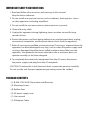
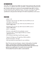
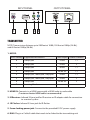
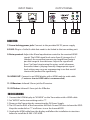
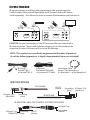
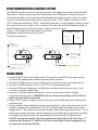
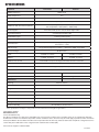
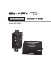
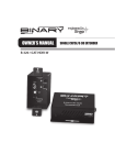
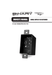
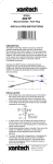
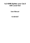
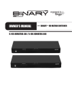
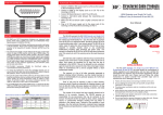
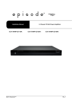
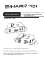
OWNER’S MANUAL
>>
Binary™ Single Cat 5e/6 HDMI 1.4
3DExtender Plus IR Receiver & Flasher
Pass-Through (130 Ft.)
B-200-1CAT-HDIR
WELCOME TO THE BINARY™ BRAND OF PRODUCTS
This product is engineered to provide years of exceptional reliability. Binary™
is one of the most highly regarded brands available today. We appreciate your
business and we stand committed to providing our customers with the highest
degree of quality and service in the industry.
IMPORTANT SAFETY INSTRUCTIONS
1. Read and follow all instructions and warnings in this manual.
Keep for future reference.
2. Do not install near any heat sources such as radiators, heat registers, stoves
or other apparatus (including amplifiers).
3. Do not install the unit near water or where moisture is present.
4. Clean with a dry cloth.
5. Unplug this apparatus during lightning storms or when unused for long
periods of time.
6. Protect the power cord from being walked on or pinched particularly at plug, convenience receptacles, and the point where it exits from the apparatus.
7. Refer all servicing to qualified service personnel. Servicing is required when the apparatus has been damaged in any way, such as when the power-supply cord or plug is damaged, liquid has been spilled or objects have fallen into the
apparatus, the apparatus has been exposed to rain or moisture, does not
operate normally, or has been dropped.
8. To completely disconnect this equipment from the AC mains, disconnect
the power supply cord plug from the AC receptacle.
CAUTION: To reduce the risk of electrical shock, inspect the premises carefully.
Do not use the unit if proper equipment grounding cannot be verified.
PACKAGE CONTENTS
• (1) B-200-1CAT-HDIR (Transmitter and Receiver)
• (4) Mounting Screws
• (8) Rubber Feet
• (2) 5V power supply units
• (1) User manual
• (1) IR Adapter Cable
INTRODUCTION
The B-200-1CAT-HDIR extends HDMI over single Cat5e/6 allowing video and audio
transmission. In addition, the B-200-1CAT-HDIR is equipped with bi-directional IR
pass-through allowing users to boost IR control distance up to 200 ft. making
IR control possible with no additional wires. The B-200-1CAT-HDIR also supports
the most advanced 3D video format, which is compliant with HDMI 1.4 3D
specifications, and guarantees the highest 3D video compatibility on the market.
FEATURES
• HDMI 1.4 3D
• Extend the transmission up to 200 ft. from the HDMI source at
HD 1080i or 720p 24-Bit
• Extend the transmission up to 130 ft. from the HDMI source at
Full HD 1080p 24-Bit
• Extend the transmission up to 65 ft. from the HDMI source at
Full HD 1080p 36-Bit
• HDCP 1.1 compliant
• Maximize adjustable 8-level equalization control
• Uncompressed 7.1 channel digital HDMI over Cat5e/6
cable transmission
• DTS-HD Master and Dolby TrueHD audio support
• Supports full frequency IR signal from 20kHz to 60kHz
• Bi-directional IR pass-through
• Wall-mountable housing design for easy installation
Note: The transmission distance is subject to the quality of installed
cable(s), source device, and display. Any keystone jack or other
connections along the transmission path will reduce the transmission
performance significantly. To minimize the chance of EMI,
STP (Shielded Twisted Pair) cable is recommended.
INPUT PANEL
1
2
OUTPUT PANEL
3 4
5
6
TRANSMITTER
NOTE: Transmission distance up to 200 feet at 1080i, 130 feet at 1080p (24-Bit),
and 65 feet at 1080p (36-Bit)
1. MODE:
EDID Setting Supported Resolutions
Color Depth Audio Channels
0
1080p @60
24-Bit
7.1
1
1080p @60
24-Bit
2
2
1080p @60
36-Bit
7.1
3
1080p @60
24-Bit 3D
7.1
4
1080p @30, 1080i @60, 720p @60
24-Bit
7.1
5
1080p @30, 1080i @60, 720p @60
24-Bit
2
6
1080p @60
24-Bit 3D
2
7
Learning Mode
—
—
2. HDMI IN: Connects to a HDMI source with a HDMI male-to-male cable
(1 meter or shorter HDMI cable is recommended)
3. IR Receiver: Infrared 3.5mm jack for IR receiver or IR adapter cable for connection
to a control system
4. IR Flasher: Infrared 3.5mm jack for IR flasher
5. Screw-locking power jack: Connect to the provided 5V DC power supply
6. RJ45: Plug in a Cat5e/6 cable that needs to be linked to the transmitting unit
INPUT PANEL
7
8
OUTPUT PANEL
9
10
11 12
RECEIVER
7. Screw-locking power jack: Connect to the provided 5V DC power supply
8. RJ45: Plug in a Cat5e/6 cable that needs to be linked to the transmitting unit
9. Rotary control: Adjust the 8-level equalization control to the received HDMI
signals. The HDMI signal level varies from 0 (strongest) to 7
(weakest) for respective transmission length from longest
possible range to short distance. Adjust the signal level
from 7 to 0 and stop turning the rotary switch whenever
the audio/video is playing normally. Inappropriate signal
level setting may cause an overpowering issue that would
shorten the product life significantly.
10. H
DMI OUT: Connect to an HDMI display with a HDMI male-to-male cable
(1 meter or shorter HDMI cable is recommended)
11. I R Receiver: Infrared 3.5mm jack for IR receiver
12. I R Flasher: Infrared 3.5mm jack for IR flasher
EDID LEARNING
1. Connect the HDMI display to “HDMI IN” on the Transmitter with a HDMI cable.
2. Set “MODE” on the transmitting unit to “7”.
3. Power on the Transmitter by connecting the 5V Power Supply.
4. The LED on the RJ45 of the transmitter will flash On and Off once to learn the EDID. Keep the mode dial on “7” at all times to use the learned EDID.
5. Unplug the HDMI cable from the display and follow the installation instructions below to install the B-200-1CAT-HDIR.
IR PASS-THROUGH
IR signals can be passed from the transmitter to the receiver over the
Cat5e/6 cable. Each unit will need both an IR Receiver and an IR Flasher
(sold separately). This allows the units to receive IR information and transmit it.
CAUTION: Incorrect connection of the IR Flasher and Receiver may result in
IR extender failure. Check carefully before plugging in the IR extender to the
respective IR sockets. Warranty will not cover the damage.
NOTE: This product was specifically engineered for Episode® IR products.
Use of the following products is highly recommended (items not included).
IR Flasher
(Episode® IRF-1
or Episode® IRF-2)
IR Receiver
(Episode® IR-SM-3660
or Episode® IR-TT-3660)
Mini Mono Cable
Binary™ B3-MonoMini-.5,
B3-MonoMini-1, or B3-MonoMini-2
SPECIFICATIONS
IR FLASHER
IR Signal (Tip)
(20-60 kHz)
Grounding
(Ring)
12V DC
(Sleeve)
Grounding IR Signal (Tip)
(Ring)
(20-60 kHz)
IR RECEIVER
IR ADAPTER CABLE FOR CONTROL SYSTEMS (INCLUDED)
IR Signal (Tip)
IR Signal (Tip)
(20-60 kHz)
Grounding
(Ring)
12V DC
(Sleeve)
Grounding
(Sleeve)
IR INTEGRATION WITH A CONTROL SYSTEM
Cat5e/6 Cable
Signal
Ground
IR OUT
SIGNAL (TIP)
(Episode® IR-SM-3660
or Episode® IR-TT-3660)
NO CONNECTION
IR RECEIVER
GROUND (SLEEVE)
12V+
The IR Receiver connection on the Transmitter is designed to operate with Episode®
IR products. When connecting the Transmitter to an IR Remote Control System or
Home Automation system to control the display from the control system, it is necessary to convert the connection from a stereo 3.5mm (1/8”) cable to a mono 3.5mm
(1/8”) cable and eliminate 12VDC. Included in the box is an IR Adapter Cable to make
this connection very simple. First, connect the male end of the IR Adapter Cable to
the IR Receiver jack on the Transmitter. Next, connect a mono
3.5mm (1/8”) cable from the female end of the
CONTROL SYSTEM
IR Adapter Cable to the control system.
SIGNAL IN
Test the connections.
MINI MONO CABLE
RECEIVER
TRANSMITTER
Binary™ B3-MonoMini-.5,
B3-MonoMini-1, or
B3-MonoMini-2
IR FLASHER
(Episode® IRF-1 or Episode® IRF-2)
INSTALLATION
1. Learn the EDID from the Display to the Transmitter (see EDID Learning section)
or select the appropriate mode (see transmitter section).
2. Connect a HDMI source (such as a Blu-ray Disc player) to the transmitting unit.
3. Connect a HDMI display (such as a LCD TV) to the receiving unit.
4. Connect IR Flashers/Receivers to both transmitting and receiving units. Use a
1 meter or shorter HDMI cable.
5. Connect a Cat5e/6 cable between the units, ensuring the cable is tightly
connected and not loose. WARNING- Do not make terminations to the CAT5e/6 while connected to the extender.
6. Plug in 5V DC power supply unit to the power jack of both the transmitting and receiving unit.
7. If you see flickering or blinking images on the display, adjust the distance control switch to improve the cable skew. Use “0” for the longest possible transmission length, and “7” for a short transmission length. Adjust the signal level from “7” to “0” and stop turning the rotary switch whenever the audio/video is playing normally.
Overpowering signal levels can significantly shorten the life of the product.
Do NOT over-power the EQ signal strength when adjusting the EQ. Start from “7” and turn dial slowly to “6” and on. Once the audio/video is working properly, do
not continue to turn the EQ dial.
SPECIFICATIONS
Technical
Transmitter
Receiver
HDMI Compliance
HDMI 1.4 3D
HDCP Compliance
Yes
Video Bandwidth
Single-link 225MHz (6.75Gbps)
Video Support
HDMI over UTP Transmission (24-bit)
Audio Support
480i / 480p / 720p / 1080i / 1080p60
Full HD (1080p)-130ft (CAT5e) / 165ft (CAT6)
HD (720p/1080i)- 165ft (CAT5e) / 200ft (CAT6)
Surround sound (up to 7.1ch) or stereo digital audio
Signal Equalization
8-level digital control at RX
Input TMDS Signal
1.2 Volts (peak-to-peak)
Input DDC Signal
5 Volts (peak-to-peak, TTL)
ESD Protection
PCB Stack-Up
(1) Human body model — ±19kV (air-gap discharge) & ±12kV (contact discharge) (2)
Core chipset — ±8kV
4-layer board (impedance control — differential 100Ω; single 50Ω)
IR Pass-Through
Bi-directional
Input
1x HDMI, 1x 3.5mm
1x RJ45, 1x 3.5mm
Output
1x RJ45, 1x 3.5mm
1x HDMI, 1x 3.5mm
HDMI Source Control
Controllable via IR pass-through from RX to TX with IR extenders
IR Remote Control
Carrier frequency: 20-60kHz
HDMI Connector
Type A (19-pin female)
RJ45 Connector
3.5mm Connector
Rotary Control Switch
WE/SS 8P8C with 2 LED indicators
IR transmitter
IR receiver
Mode
Signal level
Mechanical
Housing
Dimensions (L x W x H)
Weight
Power Supply
Power Consumption
Metal enclosure
Tx and Rx each 2.9” x 3.5” x 1”
Tx and Rx each 1.1 lbs
5V DC 2A
3 Watt (max)
Operation Temperature
32~104°F
Storage Temperature
-4~140°F
Relative Humidity
20~90% RH (no condensation)
*Note: Specifications are subject to change without notice. Dimensions and weight are approximate.
WARRANTY
2-Year Limited Warranty
This Binary™ Product has a Two-Year Limited Warranty. This warranty includes parts and labor repairs on all components found to
be defective in material or workmanship under normal conditions of use. This warranty shall not apply to products which have been
abused, modified or disassembled. Products to be repaired under this warranty must be returned to SnapAV or a designated service
center with prior notification and an assigned return authorization number (RA).
For Technical Support: 1-866-838-5052
111228