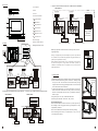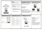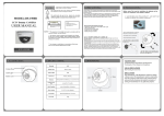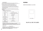
1
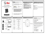
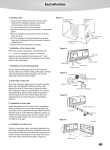
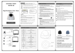
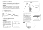
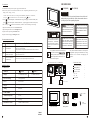
Ⅵ.OPERATION
VIDEO INDOOR PHONE
A4-F5C (COLOR)
1.Press Power switch to open/close power supply to indoor/outdoor unit.
A4-F5C-7 (COLOR)
2.When visitor presses the Call button of outdoor unit, the corresponding indoor unit will ring and
Introduction
display visitor's image, you may
a. choose not to answer the call, the image will automatically disappear 90 seconds later;
b. or press(
)to talk with the visitor. To end the talk, press(
3. Press(
)on the indoor phone,can monitor Entrance 1; by pressing again, it returns to standby state;
press (
) on the indoor phone,can monitor Entrance 2; by pressing again, it returns to standby state;
4 . The user may press(
The model number is located on the bottom and record the serial
number in the space provided below .Refer to these numbers whenever
you call upon your dealer regarding this product.
) again.
) to unlock the electronically controlled door when talking or monitoring.
5. Regulate chromaticity of the screen with Chroma control.
6. Regulate brightness of the screen with Brightness control.
7.Regulate volume of speaking with Volume control.
RISK OF ELECTRIC SHOCK
DO NOT OPEN
Ⅶ. TROUBLE SHOOTING GUIDE
1
Problem
Unit totally dead.
DO NOT EXPOSE THIS EQUIPM ENT TO RAIN OR MOISTURE
CAUTION
8.Regulate volume of ringing with Ringtone control.
No.
Possible Cause
The power is not properly connected , or no electrification is available.
The power switch is turned off.
The polarization of wiring between Indoor and outdoor units is uncorrected.
2
Call and communication
Workable,but no display.
The brightness is not properly adjusted,or the video line(white) is subject to
open circuit or short circuit.
3
Call allowed, but with no
Communication.
The voice line (red)is subject to open circuit or short circuit.
This symbol is intended to alert the user to the
dangerousvoltage
presence of uninsulated “dangerousvoltage”
within the product's enclosure that may be of
sufficient magnitude to constitute a risk of
Electric shock to persons.
SPECIFICATIONS
I. Indoor Unit
4
OR
Display
A4-F5C
5”COLOR TFT- LCD
Pattern of Wiring
4-line (polarized)
Power
AC100- 240V
Ringtone
Ding-ding dong, adjustable volume
Talking
Hand-free
Cable condition
50 m/165 ft .(RVV 22 # 4×0.65mm)
Ambient Temperature
0~40ºC
Net Weight
0 . 751 Kg
Dimension( W×D×H)
220mm×160mm×49.5mm
OR
A4-F5C-7
7”COLOR TFT- LCD
A4-F5C
A4-F5C-7
A4-M1C
A4-M2C
A4-M4C
Door
Release
A-121/
A-122
A C ( 1 0 0~2 4 0 V )
CAUTION: TO REDUCE THE RISK
OF FIRE OR SHOCK HAZARD,RE
-FERMOUNTING OF THE OPTIONAL INTERFACE BOARD TO
QUALIFIED SERVICE PERSONNEL
CAUTION: TO REDUCE THE RISK
OF FIRE OR SHOCK HAZARD,
REFER CHANGE OF SWITCH SETTING INSIDE THE UNIT TO QUALFIED SERVICE PERSONNEL
CAUTION: TO REDUCE THE RISK OF
ELECTRIC SHOCK,DO NOT REMOVE
COVER (OR BACK). NO USERSERVICEABLE PARTS INSIDE. REFER SERVICING TO QUALIFIED SERVICE PERSONNEL.
Ⅰ. F5 SYSTEM OUTLINE COMPONENTS.
Model No.
CAUTION: TO REDUCE THE RISK
OF FIRE OR SHOCK HAZARD AND
ANNOYING INTERFERENCE,USE
THE RECOMMEDED ACCESSORIES ONLY
WARNING : TO REDUCE THE RISK OF FIRE OR SHOCK HAZARD
This symbol is intended to alert the user to the presence
of important operating and maintenance (servicing)
intructions in the literature accompanying the
appliance .
Ⅱ.PARTS CHECKLIST
Indoor Phone ( Monitor )
Mounting Bracket
Screw (ST4×25mm)
Connection Cable
4#
line
2#
line
User Manual
1
1
2
2
1
1
A C ( 1 0 0~2 4 0 V )
Power
( Optional Accessories )
User Manual
4# Line
Screw
(ST4×25mm)
I ndoor Phone( Monitor )
Mounting Bracket
2# Line
V090615
MFS0 302
4
1
Ⅲ.FEATURES
* OPTION 2 (SINGLE INDOOR PHONE/TWO CAMERAS/IMAGE MEMORIER)
1) Loudspeaker
2) MIC
OUTDOOR1
1 2 3 4
3) Screen
11 10 9
12
3
2
6
8
5
7
4
5)
Monitor Button
6)
Talk Button
7)
Ringtone Button
8)
Release Button
9)
Volume Control
10)
Brightness Control
11)
Chroma Control
13) Power ON/OFF Switch
IMAGE
1 2 3 4 5 6
OFF
ON
Power
( Optional
Accessories )
Camera1
Door
Release
1
2
3
4
Camera2
1
IMAGE
2 #3 #4 5
OUTDOOR1
1 2 3 4
A-121/
A-122
1 2 3 4 5 6 7
Power
( Optional
Accessories )
ImageMemory
( Optional
Accessories )
INDOOR PHONE
6 7
1
OUTDOOR2
1
2
IMAGE
2 #3 #4 5
OUTDOOR1
1 2 3 4
1 2 3 4
Camera2
3
4
Door
Release
6 7
OUTDOOR2
1 2 3 4
Camera2
Camera1
1
2
3
4
Door
Release
1
2
2
3
4
1 2 3 4 5 6 7
Door
Release
Image Memory
( Optional
Accessories )
Door
Release
A - 121 / A - 122
Power ( Optional Accessories )
A - 121 / A - 122
Power ( Optional Accessories )
AWG 22
Wrie
( 0 . 65mm )
3
4
1.Detemine the mounting locations for both the outside camera and inside monitor.
2. At the selected monitor mounting location , attached the mounting bracket
securely to t h e wall. drill a h ole in the center area of the bra cket just large
enough for the electrical wirin g to pull through the hole. Connect the ele ctrical
w ires from the camera unit to the monitor.
3 . Attach the wired monitor unit to the wall mounting bracket by setting the
monitor over the four bracket hooks and sliding it down , Insert the tiny
machi ne s crew into the hole in the tab at the top of the bracket to hold the
monitor in place.
4.. Plug the AC power cord into a standard household outlet.
5. Place the power“ON/OFF”switch in the “ON” position.
Mounting
Bracket
Mounting
Screw
Important Mounting Notes:
Do not install the monitor and camera units where they will be exposed to dirt,
direct sunlight (or other strong light) , moisture ,high temperature( over 40℃ )
or high humidity conditions.
Do not select an installation location subjected to vibration or pounding.
Select a mounting location close to an AC outlet where it is easy to view the
screen and operate the monitor.
Door
Release
A - 121 / A - 122
A - 121 / A - 122
Power ( Optional Accessories )
2
Ⅴ. INSTALLATION
* BASIC(SINGLE CAMERA/SINGLE INDOOR PHONE) * OPTION 1 (TWO CAMERAS/SINGLE INDOOR PHONE)
INDOOR PHONE
1
Wiring is not supplied with your Video Doorphone system.Use only AWG #22
wire (0.65mm, 4-wire) and follow the appropriate wiring diagrams exactly for
optimum system performance and safety.
When planning to install the initial system, consider future system extension.
The total wire length for a single camera and monitor system(or any
combination of additional camera or monitors) must not exceed 50m for
optimum performance.
1 2 #3 #4 5 6 7
Door
Release
A-121/
A-122
4
1 2 3 4
1 2 3 4
4
3
Note: Using component “2# LINE” to connect #3,#4 shut pin when you are not
using image memory.
14
1 2 3 4
2
7
OUTDOOR1 OUTDOOR2
1 2 3 4
1
14) Ringtone Volume Control
13
3
1 2 #3 #4 5 6 7
Camera2
Camera1
12) Power Supply
Ⅳ.WIRING
2
IMAGE
OUTDOOR2
1 2 3 4
4) Power Indicator LED
1
1
INDOOR PHONE
Power ( Optional Accessories )
A - 121 / A - 122
Power ( Optional Accessories )
3