1
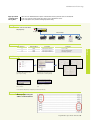
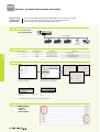
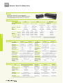
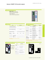
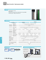
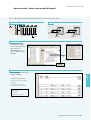
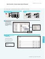
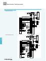
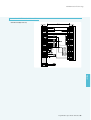
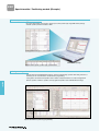
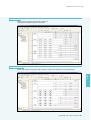
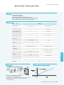
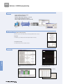
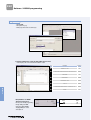
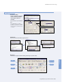
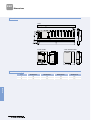
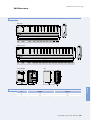
neXt Generation Technology
High-speed link
communication
among PLCs
XGT can create‘Distributed Control System’with Smart I/O, Inverter, pneumatic device via Profibus-DP.
In this case, PLC is the master and the other devices such as Smart I/O are slaves.
It just needs SyCon, basic parameter and High-speed link setting.
Configuration
PLC controls each Smart
I/O (16-point).
PLC (Master)
Profibus-DP 12Mbps
S I/O #15 (Input)
S I/O #20 (Output)
S I/O #21 (Output)
Other
LS Inverter
Data memory
Smart I/O address
PLC address
15
P0000
P0010 (P00100~P0010F)
20
P0000
P0011 (P00110~P0011F)
21
P0000
P0012 (P00120~P0012F)
Setting item
1. SyCon setting
2. XG-PD parameter setting,
3. XG5000 programming
Network
Smart I/O #
XG-PD setting
SyCon setting
For detailed setting instruction, refer to
page 43 (SyCon setting)
HS link setting
Uploading SyCon and setting up each
Smart I/O station as following example
Parameter writing
Downloading parameters to PLC after
online connection
Enable Link
Enabling link for communication
start
* For basic parameter setting and SyCon setting/change, reset the module (Online reset).
XG5000 programming
Write a program using I/O
address of Smart I/O Pnet
Programmable Logic Controller XGT Series
61
Network / Communication example (DeviceNet)
High-speed link
communication
between PLCs
XGT can create ‘Distributed Control System’ with Smart I/O, Inverter, pneumatic device via Dnet.
In this case, PLC is the master and the other devices such as Smart I/O are Slaves.
It just needs SyCon, basic parameter and High-speed link setting.
Configuration
PLC controls each
Smart I/O (16 points).
PLC (Master)
DeviceNet 500kbps
S I/O #19 (Input)
S I/O #20 (Output)
S I/O #21 (Output)
Other
LS Inverter
Data memory
Network
Smart I/O #
Smart I/O address
PLC address
19
P0000
P0010 (P00100~P0010F)
20
P0000
P0011 (P00110~P0011F)
21
P0001
P0012 (P00120~P0012F)
XG-PD setting
SyCon setting
For detailed setting instruction, refer to
page 43 (SyCon setting)
HS link setting
Uploading SyCon and setting up each
Smart I/O station as following example
Parameter writing
Downloading parameters to PLC after online
connection
Enable Link
Enabling link for communication
start
* For basic parameter setting and SyCon setting/change, reset the module (Online reset).
XG5000 programming
Write a program
using I/O
address of
Smart I/O Dnet.
62
Setting item
1. SyCon setting
2. XG-PD parameter setting,
3. XG5000 programming
neXt Generation Technology
Network / Communication example (SyCon setting Profibus, DeviceNet)
SyCon is the dedicated software that help user set up the communication environment for
Profibus-DP and DeviceNet more easily and conveniently.
Example of application
New file
Select fieldbus that is used.
Basic communication parameter setting
Select [Master] in Insert menu.
Master module setting
Select [COM-C-DNM] for DeviceNet.
Select [COM-C-DPM] for Profibus-DP.
Network
Bus parameter setting
Set up communication speed of master
module.
Master module setting
After clicking the port button, check
the right check-box.
Automatic network scan of connected Smart I/O
Perform automatic network scan after station number
setting and wiring with remote device such as Smart I/O.
At this time, all remote devices should be in normal connection (Power-On, etc).
After network scan is completed, press [Automatic Configuration] button and [OK] button.
Network checking
Check normal network (remote) condition.
Parameter download
Disconnect
Disconnect the port in Device Assignment.
Programmable Logic Controller XGT Series
63
Network / Smart I/O (Stand alone)
Features
�Wiring reduction and real time control of distributed I/O
�Supporting Rnet, DeviceNet, Profibus-DP, MODBUS (RS-422/485)
�Various I/O (DC/TR/Relay) modules with the unit of 16/32 points
Digital I/O specifications
Input
Item
No. of point
Output
DC (Sink/Source)
Transistor (Sink)
16
16
32
Rated input (Load voltage)
32
DC 24V
Input current (Load current)
DC 24V
7mA
Mixed module
DC (Sink/Source) Transistor (Sink)
Relay
16
16
16
DC 24V/AC 110V/220V
DC 24V
DC 24V
2A/5A
7mA
0.1A/2A, 0.5A/3A
Response
Off � On
3ms or less
3ms or less
3ms or less
3ms or less
3ms or less
time
On � Off
3ms or less
3ms or less
3ms or less
3ms or less
3ms or less
16 points/COM
16 points/COM
16 points/COM
16 points/COM
16 points/COM
Common
Current consumption
Rnet
Network
Network
0.1A/2A, 0.5A/3A
200mA
300mA
280mA
380mA
550mA
350mA
GRL-D22A
GRL-D24A
GRL-TR2A
GRL-TR4A
GRL-RY2A
GRL-DT4A
Profibus-DP
GPL-D22A● GPL-D24A● GPL-TR2A▲ GPL-TR4A▲
GPL-RY2A●
GPL-DT4A▲
DeviceNet
GDL-D22A● GDL-D24A● GDL-TR2A▲ GDL-TR4A▲
GDL-RY2A●
GDL-DT4A▲
MODBUS
GSL-D22A
GSL-RY2A
GSL-DT4A
GSL-D24A
GSL-TR2A
GSL-TR4A
A Sink, Rated current: 0.1A, terminal fixed type
A1 Sink, Rated current: 0.5A, terminal fixed type
Note1) Specification stated in the table is specification of type A.
Refer to XGT user’ s manual.
● A, C
▲ A, A1, B, C, C1
B Source, Rated current: 0.5A, terminal fixed type
C Source, Rated current: 0.5A, terminal separated type
C1 Sink, Rated current: 0.5A terminal separated type
Analog I/O specifications
Item
GPL-AV8C
Analog input
Digital output
GPL-AC8C
0~20mA, 4~20mA,
- 20~20mA
0~4000, 0~8000, -8000~8000
0~4000, -8000~8000
Max. resolution
1MΪ
250Ϊ
±15V
±30mA
1.25mV
2.5㎂
Digital input
Analog output
Accuracy
0~4000, 0~8000, -8000~8000
0~8000
DC 1~5V, 0~5V, 0~10V,
-10~+10V
0~20mA, 4~20mA
1KΪ or more (0~5V or 1~5V)
Load impedance
2KΪ or more (0~10V or -10~10V)
500Ϊ or less
1.25mV
Resolution
±0.3% (full scale, Ta=23�
C±5�
C)
±0.3% (full scale, Ta=0~55�
C)
±0.4% (full scale, Ta=0~55�
C)
GPL-DC4C
4 channels
Output channels
DC 1~5V, 0~5V, 0~10V,
-10~+10V
Input impedance
GPL-DV4C
Item
8 channels
Input channels
2.5㎂
±0.3% (full scale, Ta=23�C±5�C)
±0.3% (full scale, Ta=0~55�C)
±0.4% (full scale, Ta=0~55�C)
Accuracy
Conversion speed
10ms or less / 8 channel
Conversion speed
10ms or less / 4 channel
Response period
10ms or less / 8 channels + Transmission period (ms)
Response period
10ms or less / 8 channels + Transmission period (ms)
Insulation method
Analog input/output terminal with Communication terminal�Insulation
Insulation method
Analog input/output terminal with Communication terminal�Insulation
Analog input/output terminal with FG�Insulation
Analog input/output terminal with FG�Insulation
Analog input/output terminal with each channel�No insulation
Analog input/output terminal with each channel�No insulation
External power supply
DC24V (21.6 ~ 26.4)
External power supply
External current consumption
DC24V : 220mA
External current consumption
210mA
240mA
Weight (kg)
0.314
0.322
0.313
Weight (kg)
0.313
DC24V (20.4 ~ 28.8)
Communication specifications
Item
Protocol
Transmission speed
Transmission distance
Topology
Rnet (Dedicate network for LSIS Smart I/O)
Profibus-DP
DeviceNet
MODBUS
LSIS dedicated protocol
(Fnet for Remote)
Profibus-DP
(RS-485/EN50170)
DeviceNet (CAN)
MODBUS (RS-422/485)
1Mbps
9.6kbps ~ 12Mbps
125/250/500Kbps
2.4Kbps ~ 38.4Kbps
750m/segment
100m ~ 1.2Km
500/250/125m (Thin cable: 100m)
500m
Bus Token
Bus
Trunk & Drop
Bus
Transmission
Pass & Broadcast
No. of stations
Link capacity
Token Pass &
Master/Slave (Poll)
Master/Slave (Poll)
(Poll, Cyclic, COS, BitStrobe)
32/segment (Input: 32, Output: 32)
32/segment, 99/network
64
32
2,048 points/master
(64 stations ×32 points)
7Kbyte/master
2,048 points/master
64 points/station
Note1) Smart I/O supports Poll type currently, but is supposed to support Cyclic, COS and Strobe later on.
64
CSMA/NBA
neXt Generation Technology
Network / SMART I/O (DeviceNet adapter)
Features
�Max. 63 stations
�Flexible connection via DeviceNet
�Utilize same I/O modules with XGB
- Max. 512 I/O points
- Max. 32 channels analog input/output
Specification
System configuration
Items
Description
XBE-DC08A DC24V input 8pt
Group 2 only slave
XBE-DC16A DC24V input 16pt
Auto baud rate
XBE-DC32A DC24V input 32pt
Slave
XBE-RY08A Relay output 8pt
64(0~63)
XBE-RY16A Relay output 16pt
Communication Specification
Module’s Type
Max. Node Number (MAC ID)
Number of Expansion I/O Slots
8
Digital I/O
Max. DC I/O Data Size
Input:32bytes / Output:32bytes
Max. Analog Channels
Input : 16Channels / Output : 16Channels
Speed &
Comm. Speed
Distance
Distance
Input Power
125 kbps
250 kbps
500 kbps
500 m
250 m
100 m
System Power
XBE-TN08A Tr output 8pt, Sink
XBE-TP08A Tr output 8pt, Source
Max. I/O point
256points
XBE-TN16A Tr output 16pt, Sink
XBE-TP16A Tr output 16pt, Source
XBE-TN32A Tr output 32pt, Sink
XBE-TP32A Tr output 32pt, Source
DC 24V
Range
Description
Poll, Bit-strobe, COS/Cyclic
XBE-DN16A DC24V input 8pt , Tr output 8pt
19.2V ~ 28.8V(11V operate)
XBF-AD04A Current/Voltage input 4Ch
Output Voltage/
5V(±20%) /1.5A
Current
Analog,
Weight(g)
100
* When I/O module is installed, check the current consumption
(Max. Current: 1.5A)
XBF-DC04A Current output 4Ch
Temperature XBF-DV04A Voltage output 4Ch
XBF-RD04A RTD input 4Ch
16channels
XBF-TC04S TC input 4Ch
* When Digital input and Analog input is used together or Digital output Analog output is used,
configure the system within 32bytes
(Ex) If 4ch analog input is used, Digital input can be used max. 192points
Externals and inscriptions
Dimension
Item
XDL-BSSA LED
DeviceNet port
RUN
I/O ERROR
Unit : mm
LED status
ON : Normal
OFF : Module error
ON : I/O module error
OFF : Normal
Green ON: Normal
Station switch
MS
Green blink: Normal
Red ON: Module error
Green ON: Normal
Green blink: Waiting
NS
Green off: Comm. stop
Red ON: Network error
Red blink: Disconnect
Programmable Logic Controller XGT Series
65
Network
Items
Network / SMART I/O (Profibus-DP adapter)
Features
�Max. 100 stations (32stations per segment)
�Flexible connection via Profibus
�Utilize same I/O modules with XGB
- Max. 512 I/O points
- Max. 32 channels analog input/output
System configuration
Specification
Item
Performance Specification
Network
XBE-DC08A DC24V input 8pt
Interface
RS-485(Electric)
XBE-DC16A DC24V input 16pt
Polling
XBE-DC32A DC24V input 32pt
Topology
BUS
XBE-RY08A Relay output 8pt
Encoding Method
NRZ
XBE-RY16A Relay output 16pt
Sync mode , Freeze mode
Interface
Digital I/O
Auto baud rate
Master/Slave
9.6
Comm.
m
1200 1200 1200 1000
400
Distance
kbps
1500 3000 6000 12000
-
m
200
-
100
100
100
100 ( 0 ~ 99 )
Number of Expansion
8
I/O Slots
64bytes (Input:32bytes
IO Data Size
/Output:32bytes)
32Channels (Input :
Number of Analog
256points
XBE-TN32A Tr output 32pt, Sink
19.2 93.75 187.5 500
Max. Node Number
XBE-TP08A Tr output 8pt, Source
XBE-TP16A Tr output 16pt, Source
Twisted Pair Shielded Cable
Kbps
XBE-TN08A Tr output 8pt, Sink
Max. I/O point
XBE-TN16A Tr output 16pt, Sink
Slave
Cable Type
XBE-TP32A Tr output 32pt, Source
XBE-DN16A DC24V input 8pt , Tr output 8pt
XBF-AD04A Current/Voltage input 4Ch
Analog,
Temperature
XBF-DC04A Current output 4Ch
XBF-DV04A Voltage output 4Ch
16channels
XBF-RD04A RTD input 4Ch
XBF-TC04S TC input 4Ch
* When Digital input and Analog input is used together or Digital output Analog output is used,
configure the system within 32bytes
(Ex) If 4ch analog input is used, Digital input can be used max. 192points.
16Channels/Output :16Channels)
Channels
Supply Voltage : DC 24Vdc
System Power
Input Power
Description
EN50170 / DIN 19245
Media Access
Transmission
Item
Standard
19.2 ~ 28.8Vdc
Output Voltage/
5V(±20%) / 1.5A
Current
100
Weight(g)
* When I/O module is installed, check the current consumption
(Max. Current: 1.5A)
Externals and inscriptions
Dimension
Item
LED status
ON : Normal
XDL-BSSA LED
RUN
Blink: Waiting or comm. error
OFF : Module error
Profibus-DP port
I/O ERROR
ON : I/O module error
OFF : Normal
Station switch
NET
ON : Data send/receive
OFF : Disconnection
ERROR
ON : Comm. error
OFF : Normal
66
Unit : mm
neXt Generation Technology
Network / SMART I/O (Rnet adapter)
Features
�Max. 63 stations
�LS dedicated protocol (Rnet)
�Utilize same I/O modules with XGB
- Max. 512 I/O points
- Max. 32 channels analog input/output
System configuration
Specification
Performance Specification
1Mbps
XBE-DC08A DC24V input 8pt
Bus type
XBE-DC16A DC24V input 16pt
750m
XBE-DC32A DC24V input 32pt
5 pin connector
XBE-RY08A Relay output 8pt
Twisted Pair Shielded Cable
XBE-RY16A Relay output 16pt
Transmission Path
Method
Max. Cable Length
Connector type
Transmission
Cable type
Item
32(non-used repeater),
No. of Station
64( used repeater)
(Included Master)
Digital I/O
512(Input : 256, Output: 256)
Max. Digital l/O points
96
Max. Analog l/O points
Digital I/O 8
Number of I/O Slots
100
* When I/O module is installed, check the current consumption
(Max. Current: 1.5A)
256points
XBE-TP16A Tr output 16pt, Source
XBE-TP32A Tr output 32pt, Source
XBE-DN16A DC24V input 8pt , Tr output 8pt
DC24V/0.55A
Weight (g)
XBE-TP08A Tr output 8pt, Source
XBE-TN32A Tr output 32pt, Sink
handling of mode change switch
Rated Voltage/current
XBE-TN08A Tr output 8pt, Sink
Max. I/O point
XBE-TN16A Tr output 16pt, Sink
Analog I/O 4
Selection of Latch/Clear
Description
Network
Item
Tran. Rate
XBF-AD04A Current/Voltage input 4Ch
Analog,
Temperature
XBF-DC04A Current output 4Ch
XBF-DV04A Voltage output 4Ch
16channels
XBF-RD04A RTD input 4Ch
XBF-TC04S TC input 4Ch
* When Digital input and Analog input is used together or Digital output Analog output is used,
configure the system within 32bytes
(Ex) If 4ch analog input is used, Digital input can be used max. 192points.
Externals and inscriptions
Dimension
Item
XRL-BSSA LED
RUN
I/O ERROR
Rnet Port
Station switch
LED status
Unit : mm
ON : Normal
OFF : Module error
ON : I/O module error
OFF : Normal
TX
Data send
RX
Data receive
Programmable Logic Controller XGT Series
67
Network / Features
Smart I/O Rnet system
XGL-RMEA
GRL-D24A
GRL-DT4A
GRL-RY2A
GRL-TR4A
GRL-D22A
GRL-TR2A
Max. 32 stations
(including master)
/segment
Note1)
Smart I/O MODBUS system
XGL-C42A
GSL-D24A
GSL-DT4A
GSL-RY2A
GSL-TR4A
GSL-D22A
GSL-TR2A
Max. 32 stations
(including master)
Network
RS-422/485 Interface
K80S/K120S
GSL-D24A
GSL-DT4A
GSL-RY4A
GSL-TR2A
GSL-D22A
GSL-TR2A
Smart I/O Profibus-DP system
XGL-PMEA
GPL-D24A
GPL-DT4A
GPL-RY2A
GPL-TR4A
GPL-D22A
GPL-TR2A
Max. 64 stations
(including master)
/segment
Note1)
Smart I/O DeviceNet system
XGL-DMEA
GDL-D24A
GDL-DT4A
GDL-RY2A
GDL-TR4A
GDL-D22A
GDL-TR2A
Max. 64 stations
(including master)
Note1) Segment: Communication section that does not use repeater or second master.
Dimensions
�16points
�32points
*
* GxL-RY2 (16-point relay output) module follows the dimension of 32-point module.
* The length of C type Smart I/O is 47.5mm
68
Unit: mm
*
�
�
�
�
�
�
�
�
�
�
�
�
�
�
�
XGT series offer diverse special modules
such as analog, HSC, and positioning
to satisfy complicated industrial needs
Special
�
�
Special
Programmable Logic Controller XGT Series
69
�
�
�
�
�
�
�
�
�
�
�
�
�
�
�
Revolution of easy to use …XGT Special module
Fast processing of parameter and data of special module
�
�Continually refreshing operation data of special module by CPU module
�Including contact points such as conversion data of AD/DA module and
command of HSC & positioning module
Before
Easy- to-use (Easy operation parameter
setting and data monitoring)
◀ Example of programming
�Convenient parameter setting available through XG5000
�Providing useful functions that can monitor and test operation data
and contact points through XG5000
Simple maintenance (Changing online module)
�Without turning off and holding CPU, users can change special
module with ease.
Analog input module
XGF-AV8A
XGF-AC8A
XGF-AD4S
XGF-AD8A
XGF-AD16A
8 channels, voltage input
8 channels, current input
4 channels, voltage/current input
8 channels, voltage/current
16 channels, voltage/current input
Analog output module
XGF-DV4A
XGF-DV4S
XGF-DC4A
XGF-DC4S
XGF-DV8A
XGF-DC8A
4 channels, voltage output
4 channels, voltage output,insulation
4 channels, current output
4 channels, current output, insulation
8 channels, voltage output
8 channels, current output
Special
Temperature input module
XGF-TC4S
XGF-RD4A
XGF-RD4S
4 channels, thermocouple input, Insulation
4 channels, RTD input
4 channels, RTD input, Insulation
High-speed counter module
XGF-HO2A
XGF-HD2A
2 channels, Open collector
2 channels, Line driver
Positioning module
XGF-PO(1/2/3)A
XGF-PD(1/2/3)A
1/2/3-axis, Open collector
1/2/3-axis, Line Driver
Temperature controller
XGF-TC4UD
70
4 channels input: voltage/current/TC/RTD
8 channels output: current/TR
Monitoring of special module ▶
�
neXt Generation Technology
Special module / Analog input module
Features
�Fast conversion processing
�High resolution
�Setting and monitoring the special module parameter through XG5000
�Supporting 4 types of digital output data format
Specifications
Item
XGF-AV8A (Voltage input)
DC 1~5V, 0~5V,
0~10V, -10~10V
Analog input
XGF-AV8A
Digital output
XGF-AC8A
XGF-AD4S
Accuracy
Conversion speed
Max. absolute input
Digital
output
Digital
output
Digital
output
4 channels
DC 1~5V, 0~5V, 0~10V, -10~10V
DC 4~20mA, 0~20mA
DC 4~20mA, 0~20mA
Selection of input range in program or S/W package (Available to be set per channel)
Analog input
Unsigned value
Signed value
Precise value
Percentile value
Analog input
Unsigned value
Signed value
Precise value
Percentile value
Analog input
Signed value
Precise value
Percentile value
Connection terminal
No. of occupied
I/O points
Current consumption
Weight (Kg)
Configuration
XGF-AC8A
-
0~5V
0~10V
-10~10V
0~16,000
-8000~8,000
1,000~5,000
0~5,000
0~10,000
-10,000~10,000
0~10,000
4~20mA
0~20mA
0~16,000
-8,000~8,000
4,000~20,000
0~20,000
0~10,000
1~5V
0~5V
0~10V
-10~10V
-32,000~32,000
1,000~5,000
0~5,000
0~20mA
0~10,000 -10,000~10,000 4,000~20,000 0~20,000
0~10,000
Digital output
Voltage, Current,
Temperature
Flow, Pressure, etc
Transducer
PreAmp
I+
Digital output
16,000
16,000
8,000
8,000
+
Voltage
Transducer
-10V
0
10V
I+
COM
12㎃
20㎃
Current input
Insulation type
Digital output
V+
0 4㎃
Voltage input
-
COM
XGF-AD4S
4~20mA
A/D conversion characteristics
V+
XGF-AD4S
1~5V
Special
Insulation method
+
XGF-AD4S (Voltage/Current input)
1/16,000
1/64,000
1~5V
0.250mV
1 ~ 5V
62.5㎶
4~20mA
1.0㎂
4~20mA
250㎁
0~5V
0.3125mV
0~5V
78.1㎶
0~10V
0.625mV
0 ~ 10V
156.3㎶
0~20mA
1.25㎂
0~20mA
312.5㎁
-10V~10V
1.250mV
±10V
312.5㎶
±0.2% or less (Ambient temperature 25°C)
±0.05% or less (Ambient temperature 25°C)
Temp. coefficient ±16.7ppm/°C(Range of operation temperature)
±0.3% or less (Range of operation temperature)
250㎲/channel
15V
±30mA
Voltage: ±15V, Current: ±30mA
Photo-coupler Insulation between input terminal and power supply
No insulation between channels
Insulation between channels
18 points
Fixed type (Setting in basic parameter): 64 points
Variable type (Dissolving in basic parameter): 16 points
420mA
610mA
0.14
Resolution
XGF-AV8A
XGF-AC8A (Current input)
8 channels
No. of input channel
Current
+
-
Digital output
32,000
32,000
Transducer
Analog
input
Analog
input
-10V
4㎃
10V
-32,000
20㎃
-32,000
Programmable Logic Controller XGT Series
71
Special module / Analog input module
Features
�Fast conversion processing
�High resolution
�Setting and monitoring the special module parameter through XG5000
�Supporting 4 types of digital output data format
Specifications
Item
XGF-AD16A
XGF-AD8A
No. of input channel
16 channels
8 channels
Analog input
Voltage input
DC 1~5V, DC 0~5V, DC 0~10V, DC -10~10V (Input resistance: 1㏁)
Current input
DC4~20㎃, DC 0~20㎃ (Input resistance: 250Ϊ)
Input selection
Dip switch
Range selection
Selection of input range in the program or S/W package (Available to set per each channel)
Current input
Voltage input
Input type
DC 1~5V
DC 0~5V
DC 0~10V
Unsigned value
Digital output
Signed value
-8,000~8,000
Precise value
0~10,000
Percentile value
Resolution(1/16000)
0~5,000
0~10,000
-10,000~10,000
4,000~20,000
0~20,000
0.3215mV
0.6250mV
1.250mV
1.00㎂
1.25㎂
Selection of input type by program or parameter (Available to be set per each channel)
±0.2% or less (Ambient temperature 25℃), ±0.3% or less (Range of operation temperature)
Special
±15V
Max. absolute input
±30㎃
500㎲/channels
Conversion speed
Insulation method
250㎲/channels
Photo-coupler insulation between terminal and power supply
Terminal
32 points
No. of occupied I/O points (XGK)
18 points
Fixed type (Setting in basic parameter): 64 points
Current consumption
Variable type (Dissolving in basic parameter): 16 points
DC 5V : 420㎃
Wight
140g
Configuration
-
A/D conversion characteristics
+
-
Transducer
PreAmp
Digital output
Voltage, Current,
Temperature, Flow,
Digital output
Max. 10,000 8,000 16,000
Pressure, etc
Min. 5,000
Mid.
0
8,000
0 -8,000 0
-10V
1V 5V
10V
Voltage input
Unsigned value
Signed value
Percentile value
72
DC 0~20㎃
0.2500mV
Resolution
+
DC 4~20㎃
1,000~5,000
Range selection
XGF-AD8A
DC -10~10V
0~16,000
4mA 10mA12mA 20mA
Current input
neXt Generation Technology
Special module / Analog input module (Example)
This is a simple example to start Analog input module setting. For more details, refer to user’s manual.
System configuration
Wiring
Voltage type
sensor
Current type
sensor
Analog input module (Slot 2)
Sensor
XGF-AV8A
XGF-AC8A
Parameter setting
In the parameter setting box,
select slot and analog module
that you want to use.
(This example shows to
select‘0’channel of voltage
input type.)
You need to fill out each item suitable for
your system.
Press the <Details> button at lower end of parameter setting box after
selecting the module.
Programming
Special
Create a program for A/D conversion
(0~10V to 0~16,000).
Special devices for programming
Refer to user’s manual for more details.
U02.0.0: Error
U02.11.0: Requesting error-clear
U02.02: Memory of channel A/D value
Uxy.aa.bb
x: Base number
y: Slot number
aa,bb: Refer to user’s manual.
Programmable Logic Controller XGT Series
73
Special module / Analog output module
Features
�Fast conversion processing
�High resolution
�Setting and monitoring the special module parameter through XG5000
�Supporting 4 types of digital input data format
Specifications
XGF-DV4A,XGF-DV8A, XGF-DV4S (Voltage output type)
Item
No. of output channel
XGF-DC4A,XGF-DC8A, XGF-DC4S (Current output type)
XGF-DV4A/4S, XGF-DC4A/4S : 4 channels / XGF-DV8A, XGF-DC8A : 8 channels
Analog output range
DC 1~5V, 0~5V
DC 4~20mA
DC 0~10V, -10~10V
DC 0~20mA
Selection of input range in the program or S/W package (Available to set per each channel)
Voltage type
1~5V
0~5V
Analog
output
Digital input
1,000~5,000
Precise value
0~5,000
4~20㎃
-10,000~10,000
0~20㎃
0~16,000
-8,000~8,000
Signed value
Digital input
0~10,000
0~10,000
Current type
Unsigned value
Analog
output
-10~10V
-8,000~8,000
Signed value
Percentile value
Digital input range
0~10V
0~16,000
Unsigned value
4,000~20,000
Precise value
0~20,000
0~10,000
Percentile value
16-bit binary value: selection of input type by program or parameter (Available to be set per each channel)
1/16,000 (Per each input range)
Max. resolution
1~5V
0.250㎷
0~5V
0.3125㎷
0~10V
0.625㎷
±10V
1.250㎷
4~20㎃
1.0㎂
0~20㎃
1.25㎂
XGF-DV4A/8A, DC4A/8A : ±0.2% or less (Ambient temperature 25℃), ±0.3% or less (Range of operation temperature)
Accuracy
XGF-DV4S/DC4S : ±0.1% or less (Ambient temperature 25℃), temp coefficient: ±80ppm/℃
Conversion speed
250㎲/channel
±15V
Max. absolute output
±24㎃
Special
Photo-coupler insulation between terminal and power supply
Insulation method
XGF-DV4A/8A, XGF-DC4A/8A: No insulation between channels
XGF-DV4S, XGF-DC4S (Insulation type): Insulation between channels
Connection terminal
18 point terminal
No. of occupied
Fixed type (Setting in basic parameter): assign 64 points
points
Variable type (Dissolving in basic parameter): assign 16 points
Current
consumption (mA)
DV4A
DV8A
DV4S
DC4A
DC8A
DC4S
Internal
190
190
200
190
190
200
External
140
180
150
210
300
220
Weight (Kg)
0.15
Output wiring
I/O conversion characteristics
Voltage output
XGF-DV4A/4S/8A
XGF-DC4A/4S/8A
Controller
(Heater, Valve, etc.)
Power conversion
4~20mA
C
H
0
+
C
H
+
_
1
2
3
Current output
10V
20㎃
0V
12㎃
0~220V
+
-
P
-10V
0
8,000
16,000
4㎃
0
Digital input
N
8,000
16,000
Digital input
Insulation type
Voltage output
Current output
10V
20㎃
Digital
input
0V
Digital
input
16,000
-10V
74
4㎃
0
16,000
neXt Generation Technology
Special module / Analog output module (Example)
This is a simple example to start Analog output module setting. For more details, refer to user’s manual.
System configuration
Wiring
L
Voltage
manipulation
type load
Analog output module (Slot 2)
L
Current
manipulation
type load
24V
XGF-DV4A
24V
XGF-DC4A
Device
Parameter setting
In the parameter setting box,
select slot and analog
module that you want to use.
(This example shows to
select ‘0’ channel of voltage
output type.)
You need to fill out each item suitable
for your system.
Press the <Details> button at lower end of parameter setting box after
selecting the module.
Programming
Special
Create a program for D/A conversion
(0~16000 to 0~10V).
Special devices for programming
Refer to user’s manual for more details.
U02.02.0: Admitting Channel 0 output
U02.03: Output data of channel 0
Uxy.aa.bb
x: Base number
y: Slot number
aa,bb: Refer to user’s manual.
Programmable Logic Controller XGT Series
75
Special module / High-speed counter module
Features
�Parameter setting and monitoring using XG5000
�Incremental encoder available
�Supporting various pulse input (5V, 12V, 24V)
�Various multiplication (1/2 phase pulse input)
�External present input
�Providing function to prevent from counting external signal
�Supporting HTL-level incremental encoder in the line-drive input type
Specifications
Specification
Item
XGF-HO2A
XGF-HD2A
Signal
A Phase, B Phase
Input type
Voltage input (Open Collector)
Differential input (Line Driver)
Signal level
DC 5/12/24V
RS-422 Line Drive/HTL LEVEL Line Drive
Input voltage
No. of
command
Input current
24V DC
(17.0V ~ 26.4V)
12V DC
(9.8V ~ 13.2V)
5V DC
(4.5V ~ 5.5V)
7~11mA
7~11mA
7~11mA
Min. On guaranteed voltage
17.0V
9.8V
4.5V
Max. Off guaranteed voltage
4.5V
Set by program (Count only in‘Enable’)
200Kpps
500Kpps (HTL input: 250Kpps)
No. of channels
2 channels
Counting range
Signed 32 Bit (-2,147,483,647 ~ 2,147,483,647)
Counting type
Linear count
(Program setting)
(Generating Carry/Borrow when exceeding counting range, Max/Min value)
1 Phase input
Input mode
2 Phase input
(Program setting)
CW/CCW input
Voltage
Signal type
Special
Up/Down
counter setting
Multiplication
1-phase input
Program or B-phase
2-phase input
Phase difference
CW/CCW
A-phase input: Up count
1/2 multiplication (Programming)
2-phase input
1/2/4 multiplication (Programming)
Signal
Control input
1 multiplication
Preset signal, Signal to admit additional signal (Setting by terminal block or programming)
Signal level
DC 5V/12V/24V input type (Selecting terminal)
Signal type
Voltage
No. of output point
External output
Operating
status display
Addition functions
(Program setting)
2 points/channel: Terminal output available
Type
Single comparison (>,>=,=,=<,<) or section comparison
Output type
Open Collector (Sink)
Input signal
A-phase, B-phase, Preset signal, Signal to admit additional signal
Output signal
OUT1, OUT2
Operation status
Module Ready, Pulse input status of A, B phase
∙Count clear, Count latch
∙Pulse frequency count (Each input channel)
∙Section count (Set time value:1~60000ms)
∙Measuring counting number per a unit time (Set time value:1~60000ms)
∙Preventing from counting (Setting by internal/external input during counting)
Fixed type (Setting in basic parameter): 64 points
No. of occupied
Variable type (Dissolving in basic parameter): 16 points
I/O points
40-pin connector
Terminal block
Current consumption
Weight (Kg)
B-phase input: Down count
1-phase input
CW/CCW
76
RS-422 Line Drive
HTL Level Line Drive
1.7V
3.0V
Counter enable
Max. counting speed
Line Driver
270
330
0.09
neXt Generation Technology
Terminal block configuration
XGF-HO2A
Pin layout
Signal name
Pin layout
Signal name
CH1
A phase DC12V input
1
17
AI-
AI-Input (LINE DRIVE TTL LEVEL Input)
A phase DC24V input
2
18
AI+
AI+Input (LINE DRIVE TTL LEVEL Input)
A_C
A phase COM
3
19
AII-
AII-Input (LINE DRIVE HTL LEVEL Input)
20
A5V
A phase DC5V input
AII-
AII+
4
20
AII+
AII+Input (LINE DRIVE HTL LEVEL Input)
5
21
B12V
B phase DC12V input
BI-
BI+
5
21
BI-
BI- Input (LINE DRIVE TTL LEVEL Input)
6
22
B24V
B phase DC24V input
BII-
BII+
6
22
BI+
BI+Input (LINE DRIVE TTL LEVEL Input)
7
23
B_C
B phase COM
P_C
7
23
BII-
BII-Input (LINE DRIVE HTL LEVEL Input)
G12V G24V
8
24
B5V
B phase DC5V input
G12V G24V
8
24
BII+
BII+Input (LINE DRIVE HTL LEVEL Input)
G_C
9
25
P12V
Preset DC12V input
AI+
25
P12V Preset DC12V input
AI-
9
A5V
10
26
P24V
Preset DC24V input
AII-
AII+
10
26
P24V Preset DC24V input
B12V B24V
11
27
P_C
Preset COM
BI-
BI+
11
27
P_C
Preset COM
12
28
P5V
Preset DC5V input
BII-
BII+
12
28
P5V
Preset DC5V input
13
29
G12V
Gate DC12V input
P_C
13
29
G12V Gate DC12V input
14
30
G24V
Gate DC24V input
G12V G24V
14
30
G24V Gate DC24V input
15
31
G_C
Gate COM
15
31
G_C
Gate COM
16
32
G5V
Gate DC5V input
CH1 OUT1 OUT0
16
32
G5V
Gate DC5V input
33
35
OUT1 Comparison output OUT1
24V
33
35
OUT1 Comparison output OUT1
34
36
OUT0 Comparison output OUT0
34
36
OUT0 Comparison output OUT0
37
38
24V
External power supply
39
40
24G
DC24V
CH1
1
17
A12V
2
18
A24V
3
19
4
B12V B24V
B_C
A_C
A5V
B5V
AI-
CH0
P12V P24V
P_C
P5V
G5V
A_C
B_C
B5V
P12V P24V
P_C
P5V
G12V G24V
G_C
G5V
CH0 OUT1 OUT0
CH1 OUT1 OUT0
24V
24V
24G
24G
+
DC24V
37
38
24V
External power supply
39
40
24G
DC24V
CH1
AI+
P12V P24V
G_C
A12V A24V
CH1
Pin number
CHO
CHO
A12V A24V
CH0
XGF-HD2A
Pin number
P5V
G5V
P12V P24V
G_C
P5V
G5V
CH0 OUT1 OUT0
24G
+
24V
24G
DC24V
Configuration
Setting preset value
HO2A/
HD2A
A Phase input
Encoder
Motor
B Phase input
Setting set value
CH0
Counter admission, Reset,
Output admission
Reading operation status
Reading counting value
Gate input
Special
Preset input
Writing operation status
CPU
Inverter
Output 1 (Comparison signal)
CH1
Output 2 (Comparison signal)
PLC analog
output
Programmable Logic Controller XGT Series
77
Special module / High-speed counter module (Example)
This is a simple example of high-speed counter module setting.
For more details, refer to user’s manual.
System configuration
Wiring
XGF-HD2A
ENCODER
ENCODER
2 Phase 1 multiplication
(A, B Phase)
XGF-HD2A Slot 2
Counter output (OUT0)
DC 24V
DC 5V
* This is wiring diagram of line driver. For
open collector or other control, refer to
user’s manual.
Control configuration
�Light a lamp of output when present value reaches 1000 of pulse input counted by encoder.
�Current value of pulse is saved in D100~D101 and is monitored.
Module test (Online)
�Module test function of XGT enables to monitor operation status of high-speed counter module and to test-run.
Special
Select [Monitor] → [Special Module
Monitoring] in menu and appoint
high-speed counter.
After pressing the button for
[Start Monitoring],
press the button [FLAG monitor].
Change [Counter Enable]
status to ON.
Check current counting value in‘Monitor
Special Module’screen box.
78
neXt Generation Technology
Parameter setting
�In I/O parameter setting box, select slot and analog module
that you want to use.
(This example shows to select 2-channel line driver.)
Press the <Details> button at lower end of parameter setting
box after selecting the module.
Input 1000 as Max. and Min. comparison output.
Programming
�After completing programming like following figure, download it to PLC and check operation status.
Special devices for programming
Refer to user’s manual for more details.
U02.23.0: Count operation admission
U02.23.1: Count preset
U02.23.4: Consistent output admission
Uxy.aa.bb
x: Base number
y: Slot number
aa,bb: Refer to user’s manual
U02.23.5: Output external terminal admission
U02.23.6: OUT0 consistent signal reset
U02.00.6: Contact for checking external output (Practically effective output is outputted
Special
through OUT0 terminal)
U02.02~U02.03: Counter present value
After downloading, monitor operation status.
For monitoring just present value, follow the example.
Programmable Logic Controller XGT Series
79
Special module / Positioning module [APM]
Features
�Highly reliable position control with LSIS ASIC-embedded processor
�Enhanced control with fast control processing speed
�High-speed motor control (Max. pulse output: 1Mbps)
�Circular/linear interpolation, separate/synchronous operation
�Trapezoidal & S-curve acceleration/deceleration
�Easy and quick control through external input (JOG operation included)
�Encoder input support
�High-speed processing of command (4ms)
�Easy to set positioning parameters (Windows)
�Monitoring/Tracking/Simulation
�Available to edit operation parameter data in EXCEL
�Self-diagnosis
�Real-time information and solution for each error
Specifications
Specifications
Item
XGF-PO1A, XGF-PD1A
XGF-PO2A, XGF-PD2A
XGF-PO3A, XGF-PD3A
1
2
3
Number of axis
Interpolation
2-axis linear interpolation, 2-axis circular interpolation 2/3-axis linear interpolation, 2-axis circular interpolation
Control method
Position control, speed control, speed/position control, position/speed control
Setting unit
Pulse, mm, inch, degree
Positioning data
Each axis has 400 data items (Operation step number 1�400). It is available to set with software package or programming.
Software package
Available (Connected with RS-232C Port of CPU module)
Data backup
Flash memory (No battery)
Positioning method
Special
Position
address
range
Absolute / relative method
mm
-214748364.8 � 214748364.7 (㎛)
Inch
-21474.83648 � 21474.83647
Degree
-21474.83648 � 21474.83647
Pulse
-2147483648 � 2147483647
Type
Positioning
Position
speed
range
XGF-PO�A: Open collector, XGF-PD�A: Line Driver
mm
0.01 � 20000000.00 (㎜/min)
Inch
0.001 � 2000000.000 (inch/min)
Degree
0.001 � 2000000.000 (degree/min)
Pulse
XGF-PO�A: 1~200,000 (pulse/sec), XGF-PD�A: 1~1,000,000 (pulse/sec)
Accel/Decel pattern
Trapezoidal & S-curve acceleration/deceleration
Accel/Decel time
1 � 65,535㎳
XGF-PO�A: 200Kpps / XGF-PD�A: 1Mpps
Max. output pulse
XGF-PO�A: 2m / XGF-PD�A: 10m
Max. distance
200 Kpps
Max. encoder input
LED
Error display
LED
Operation display
Connection connector
40 Pin connector
Size of cable
AWG #24
Occupied points of I/O
Current consumption (mA)
Weight (kg)
※ XGF-PO�O: Open Collector type, �: Number of axis
XGF-PD�D: Line Drive type, �: Number of axis
80
64 points (Fixed type), 16 points (Variable type)
XGF-PO1A: 340
XGF-PO2A: 360
XGF-PO3A: 400
XGF-PD1A: 510
XGF-PD2A: 790
XGF-PD3A: 860
0.12
0.13
0.135
neXt Generation Technology
Terminal block configuration
Pin layout
Pin number
For
A
x
i
s
Signal direction
Signal name
X
Y
Z
21
41
61
FP+
Pulse output (Differential +)
→
22
42
62
FP-
Pulse output (Differential -)
→
23
43
63
RP+
Pulse sign (Differential +)
→
24
44
64
RP-
Pulse sign (Differential -)
→
25
45
65
OV+ *
High limit
�
26
46
66
OV- *
Low limit
�
27
47
67
STOP
External stop signal
�
28
48
68
DOG
Approximate origin
�
29
49
69
VTP
Speed/Position switching signal
30
31
32
50
51
52
70
71
72
ECMD
JOGCOM
Start
�
command
Skip
�
signal
JOG+ (Forward)
�
�
JOG reverse operation
Common
⇔
33
53
73
DR/INP
Imposition/Driver Ready signal
�
34
54
74
DR/INP COM
Imposition/Driver Ready signal Common
⇔
35
55
75
HOME +24V
Zero signal (+24V)
�
36
56
76
NC
Not used
37
57
77
HOME +5V
Zero signal (+5V)
�
38
58
78
HOME COM
Zero signal (+24V, +5V) Common
⇔
39
59
79
24V
24V Power supply (Not used in case of line drive output)
40
60
80
P COM
External 24V GND (Not used in case of line drive output)
1
MPG A+
Manual pulse generator/Encoder A+ Input
�
2
MPG A-
Manual pulse generator/Encoder A- Input
�
3
MPG B+
Manual pulse generator/Encoder B+ Input
�
4
MPG B-
Manual pulse generator/Encoder B- Input
�
5
NC
Not used
�
6
NC
Not used
�
7
CON
External simultaneous start
�
8
EMG *
Emergency stop
�
9
NC
Not used
10
11~20
COM
(CON, EMG) Common
NC
Not used
Special
C
o
m
m
o
n
Condition
�
External
(OV+, OV-, STOP, DOG, VTP, ECMD, JOG-)
1 axis
2/3 axes
APM - Ext. device
⇔
Programmable Logic Controller XGT Series
81
Special module / Positioning module
Connection with MR-J2/J2S-�A
�XGF-PD1/2/3A (Line Driver)
Power
3phase 200VAC
Electronic
brake
OFF of Servo ON signal
Cutoff by alarm signal
Within 10m
Detector
High limit
Low limit
External stop
Approx. origin
VTP switching
External Comm.
Jog reverse
Monitor output
External EMG
Max. 10mA
Servo ON
Reset
Proportinal control
Torqe limit
Normal limit
2m less
Reverse limit
MPG
External
simultaneous start
Emergency stop
Failure Zero
speed detection
During torque
limit
Analog torque limit
+10V/Max. current
2m less
�XGF-PO1/2/3A (Open Collector)
Power
3phase 200VAC
Special
Electronic
brake
OFF of Servo ON signal
Cutoff by alarm signal
Within 2m
Detector
High limit
Low limit
External stop
Approx. origin
Monitor output
VTP switching
External EMG
External Comm.
Servo ON
Jog reverse
Reset
Max. 100mA
Proportinal control
Torqe limit
Normal limit
Reverse limit
MPG
External
simultaneous start
Emergency stop
Failure Zero
speed detection
During torque limit
Analog torque limit
+10V/Max. current
2m less
82
2m less
neXt Generation Technology
Connection with FDA-3000 AC Servo driver
�XGF-PO1/2/3A (Open Collector)
Max. 2m
High limit
Low limit
External stop
Approx. origin
VTP switching
External Comm.
Jog reverse
MPG
External
simultaneous start
Emergency stop
Special
Programmable Logic Controller XGT Series
83
Special module / Positioning module
Connection with FDA-5000 AC Servo driver
�XGF-PO1/2/3A (Open Collector)
Max. 2m
High limit
Low limit
External stop
Approx. origin
VTP switching
External Comm.
Jog reverse
MPG
External
simultaneous start
Emergency stop
�XGF-PD1/2/3A (Line Driver)
Max. 10m
Special
High limit
Low limit
External stop
Approx. origin
VTP switching
External Comm.
Jog reverse
MPG
External
simultaneous start
Emergency stop
84
neXt Generation Technology
Special module / Positioning module (Example)
This is a simple example to control 1-axis servo motor.
System configuration
�Positioning system consists of control part, power part, and machinery part.
�Control part: Install APM module on base and complete parameter setting and programming.
�Power part: Power part generates momentum, and it consists of [servo-driver + servo-motor] and [step-driver + step-motor].
�Machinery part: Machinery part is to transport objects, and it can be ball screw, timing belt and rack gear.
Control part
Power part
Machinery part
System design
�APM: Determine type and quantity considering the number of control axis and operation function.
�Driver: Select driver with identical output type of APM.
(In case output type of APM is line driver, driver should support a pulse train input type of line driver.)
�Motor: Select capacity considering operation characteristics of load.
�Mechanical: Design precise mechanical system to minimize error.
Special
Connection to drivers
�The following picture is wiring pulse train signal between driver and APM for pulse train signal.
�Terminal besides pulse train signal is used additionally according to user-purpose, system characteristics.
�For wiring of optional terminal of Servo (Step) driver, refer to user’s manual.
Line driver
Open collector
Programmable Logic Controller XGT Series
85
Special module / Positioning module (Example)
Parameter, data setting and transmission
�Set system characteristic, target location, operation speed, and operation type using APM software package.
�Transmit operation parameter and data to APM.
Setting parameter of system characteristic
APM software package
Target location, speed, operation type, operation data
Initial system inspection
�Perform a trial-run using APM Software Package, and check external wiring, operation data setting, and status of
machinery part. It is recommended to do trial-run before programming.
�If a program is saved in CPU and operation mode is ’RUN’, a unexpected fault can occur due to disagreement
between operation condition of operation control program and operation result of APM Software Package.
Special
Operate APM without positioning programming
86
neXt Generation Technology
Programming
�Create a program using dedicated command for APM control.
ex) Origin point return-ORG, Independent operation-IST
Program monitoring
�Monitor output condition following input condition and inspect operation status of APM and correct programming error.
Special
Programmable Logic Controller XGT Series
87
Special module / RTD input module
Features
�Supports various additional functions (average, alarm, filter)
�Special module parameter setting and monitoring with XG5000
�Supports digital conversion, temperature display and user scaling
Specifications
Item
No. of input channel
Input sensor type
Temperature input range
Digital output
Accuracy
Temperature
display
(unit: 0.1)
Pt100
JPt100
PT1000
NI100
Pt100
JPt100
PT1000
NI100
Pt100
JPt100
PT1000
NI100
Scaling display
(Customize)
Normal temp.(25°C)
Full temp.(0~55°C)
XGF-RD4A
XGF-RD4S
4 channels
JIS C1604-1997
JIS C1604-1981, KS C1603-1991
-200.0 ~ 850.0°C
-200.0 ~ 640.0°C
-2,000 ~ 8,500
-2,000 ~ 6,400
-
4 channels
JIS C1604-1997
JIS C1604-1981, KS C1603-1991
JIS C1604-1997
DIN 43760-1987
-200.0 ~ 850.0°C
-200.0 ~ 640.0°C
-200.0 ~ 850.0°C
-60.0 ~ 180.0°C
-2,000 ~ 8,500
-2,000 ~ 6,400
-2,000 ~ 8,500
-2,000 ~ 1,800
0 ~ 65535
-32768 ~ 32767
±0.2%
±0.3%
40ms / channel
Conversion speed
Insulation
±0.1%
±70ppm/ °C
Channel to Channel
Terminal to PLC Power
Non-insulation
Insulation
Photo-coupler
3-wire
Wiring method
Average
Function
Alarm
Special
Filtering
Terminal block
Current consumption
Weight [g]
4-wire
Time average (320~64000ms)
Counting average(2~64000 count)
Moving average(2~100 samples)
Process alarm
Input changing rate alarm
Disconnection detection
Digital filter (160~64000ms)
18-point terminal block
5V: 450mA
5V: 720mA
150g
Characteristics of temperature conversion
Wiring
1) When sensor and compensating wire are shielded, shield-connection to FG terminal of the module is available.
2) The wiring of 4-wire type sensor is identical with the wiring of 3-wire type sensor. 3 wires is connected to the module. But the other wire is not connected with the module.
88
neXt Generation Technology
Special module / Thermocouple module
Features
�Insulation between channels
�±0.1% (25℃) constant density
�Supports various input sensor (supporting C-type sensor)
�Various additional functions (average, filter, alarm, max/min value display)
�Special module parameter setting and monitoring with XG5000
Specifications
Item
XGF-TC4S
4 channels
Input channels
Input sensor type
K, J, E, T, B, R, S, N, C
JIS C1602-1995ITS-90
K
-250 ~ 1350℃
Input temperature range
J
-200 ~ 1200℃
E
-250 ~ 1000℃
T
-250 ~ 400℃
B
400 ~ 1800℃
R
-50 ~ 1750℃
S
-50 ~ 1750℃
N
-270 ~1300℃
C
0 ~ 2300℃
Temperature display (unit: 0.1)
Display down to the first decimal place (0.1℃)
Digital output
Scaling
0 ~ 65535
(User range setting)
-32768 ~ 32767
±0.1%
Normal temp. (25℃)
Accuracy
Some section can permit 0.5%
±100ppm℃
Temperature coefficient (Operating temp. range)
40ms/ channel
Conversion speed
Insulation
Between channels
Insulation
Between terminals and power
Insulation(Photo-Coupler)
Compensation
Automatic compensation by RJC sensing (PT100)
±1.0%
Compensation degree
Average time (320 ~ 6400ms)
Average
Average number (2~ 64000)
Average move (2 ~100)
Special
Function
Process Alarm
Alarm
Change rate alarm
Filter
Digital filter (160 ~ 64000ms)
Burn-out detection
Max./Min. values display
Terminal block
Current consumption
Weight (kg)
Input wiring
Max./Min. values display
18-point terminal block
5V : 610mA
0.150
Characteristics of I/O conversion
1) When sensor and compensating wire are shielded,
shield connection to FG terminal is available.
2) To minimize an error, overall temperature of block terminal need to be equal.
3) Compensating sensor should be the same type of sensor which is
used for measurement.
Programmable Logic Controller XGT Series
89
Special module / Temperature controller
Features
�Optimum temperature control
�Universal input: TC, RTD, Voltage, Current
�Isolated input
�Output: Current/Transistor
�Parameter setting via dedicated software: TG-CON
�Variety of control types
- PID control
- Cascade control
- On/ Off control
�Disconnection detection
�Various input functions: Bias, Filter, Square root
�Auto-tuning
Specifications
Item
XGF-TC4UD
No. of loop
4 loops
K
-200 ~ 1300℃
0 ~ 500℃
J
-200 ~ 1200℃
0 ~ 500℃
E
Thermo
couple
Special
Input
RTD
-200 ~ 1000℃
T
-200 ~ 400℃
B
400 ~ 1800℃
R
0 ~ 1700℃
S
0 ~ 1700℃
N
-200 ~ 1300℃
C(W5Re/W26Re)
0 ~ 2300℃
PL II
0 ~ 1300℃
L
-200 ~ 900℃
U
-200 ~ 600℃
Pt100
-200 ~ 850℃
JPt100
-200 ~ 600℃
Pt1000
-200 ~ 800℃
0 ~ 10mV
DC mV
0 ~ 100mV
0 ~ 1V
1 ~ 5V
Voltage
DC V
0 ~ 5V
0 ~ 10V
-5V ~ 5V
10V ~ 10V
Current
Input channel
90
DC mA
4 ~ 20mA
0 ~ 20mA
4 channels (Input type selection per channel)
neXt Generation Technology
Specifications
Item
XGF-TC4UD
Resolution
Cold junction
compensation
Resolution Refer to the user’s manual (Resolution for each input type)
Automatic compensation by RJC sensor
Compensation
±0.2℃
Precision
0.1℃/1℃ (Selection by software)
Temperature display
Digital output
0~1000
Linear display
Only for voltage/current
Scale display
input Range : -3,000~3,000 Setting range: 0~3000
Control type
0.2sec/4 loops
Conversion speed
PID, On/Off control
Selection per input type
Set value (SV)
0 : ON/OFF control, Real type
Gain
Parameter
0 : No Differential control, Real type
Integrated time
Differential time
0 : No Integrated control, Real type
No. of output channel
8 channels (PWM or analog output)
Rated load voltage
DC 24V
Max. current point
0.1A points
On voltage drop
DC 0.3V or less
Off leakage current
PWM
Response time
0.1mA or less
1ms or less
ON ⇒ OFF
1ms or less
OFF ⇒ ON
Output
Periodic
0.5~120.0sec (resolution: 0.5sec)
Time resolution
High value between 10ms or 0.5% of full scale
Range
Analog output
4~20mA
Resistance
600Ϊ or less
Resolution
±1.0%, 25℃
Precision
Item
Insulation
8㎂
Insulation
Insulation withstand voltage
Insulation resistance
Channel - Channel
Trans
Input terminal - PLC
Photocoupler
500V AC, 50/60Hz 1min,
Leakage 10mA or less
500V DC,
10MΪor more
Special
Current output - Current output
Non insulation
External power- Output
Warm-up
20min or more
Terminal
18 points terminal
Power
5V, DC 24V (external)
DC 5V : 900mA (Internal)
Current consumption
DC 24V : 300mA (external)
Example: Constant temperature
Manual MV value
Signal converter
MV
Power converter
SV data
register
Heater
PV data
register
PID
calculation
MV data
register
Digital to analog
Target
PWM
Electric circuit
PT100
Analog to digital
Sensor
Programmable Logic Controller XGT Series
91
☞
☞
☞
☞
☞
☞
☞
☞
☞
☞
☞
☞
☞
☞
☞
☞
☞
Software
Software innovation for integrated solution.
XG5000 is the optimum software which can cover various
programming needs, debugging, and easy maintenance. Especially,
XG-PD achieves customer satisfaction with useful
maintenance tool by internet.
Software
XG5000
XG-PD
92
APM S/W
package
☞
☞
☞
☞
☞
☞
n e
☞
☞
☞
☞
☞
G
T
X
t
e n e r a t i o n
e c h n o l o g y
Programming software XG5000
�Program editing & Engineering software
�Windows-based easy operation
�Multi-PLC, Multi-programming support
�Various monitoring and diagnosis functions
�Windows 2000, XP (Limited use in Windows 98, ME)
Variable monitor
Ladder monitor
Forced I/O
System monitor
Special module monitor
Trend monitor
Network set up, diagnosis
Positioning
XG5000
XG-PD
APM S/W Package
Easy how to use
Letter type, color, short key, tool bar
Communication module parameter
setting
Basic, high-speed link parameter setting
Easy parameter setting
System diagnosis and monitoring
Ping/Self test
Monitoring of sending/receiving frame
Display of status and diagnosis of each
module
Monitoring and trace
Convenient editing
Undo, Redo, Excel editing
Structuralized program
Scan, task (Initialization, normal cycle,
external contact point, internal device)
Software
Programming
Data editing in Excel
Various monitoring
Special module, trend,
user-event, etc
Programmable Logic Controller XGT Series
93
Software / XG5000 programming
Features
�Program editing & Engineering software
�Windows-based easy operation
�Multi-PLC, Multi-program, Multi-task in one project
�Various monitoring and diagnosis functions
�Windows 2000, XP (Limited use in Windows 98, ME)
Connection
-Direct connection with
CPU (USB, RS-232C)
-Ethernet
-Modem
Programming tools
MPMP (Multi-PLC Multi-programming)
Different PLC systems can be edited, monitored, and managed simultaneously in one project.
Drag & Drop
It is available in project, variable/comment, ladder diagram editing and monitoring.
User-defined shortcut keys
User-defined shortcut keys increase editing convenience.
Monitoring
Software
Special module monitoring
Monitoring and test-run of various special modules are
available.
Trend monitoring
The changing value of specific device can be
monitored and saved as a file.
Device monitoring
System monitoring
Variable monitoring
94
neXt Generation Technology
System requirement
System requirement
Item
O/S
Windows 2000, XP (Limited use in Windows 98, ME)
CPU
IBM compatible PC with Min. 200MHz Pentium processor
Min. 128M
Memory
100 MB (Free memory space)
HDD
Communication port for program transmission (RS-232C, USB)
Serial port
Printer
Compatible with Windows 98 or later
Mouse
Compatible with Windows 98 or later
Variable and programming editing
�Data input like EXCEL
�Cell-unit edit
�Auto Fill function
�Compatible with
Microsoft Excel
�Redo and Undo
(Unlimited)
�Segment screen edit
Improved diagnosis and maintenance
User-defined event
By registering user-defined event, users can read the record of
specified event and use it for PLC operation and debugging.
Forced I/O
The status of external output device can be
checked without program.
And when input device breaks down,
forced input function specifies ON/OFF and can
operate the system without interruption of
equipment.
I/O skip, Error Mask
I/O inspection and renewal can be set for specific
module and continuous operation is available when
an error is occurred.
Software
Module exchange wizard
It supports safe module exchange during‘RUN’
mode.
Programmable Logic Controller XGT Series
95
Software / XG5000 programming
Program editing
�Start XG5000
�Select [New Project]
�Write project name and select CPU type
Configure ladder lines as below with ladder input tool bar
�Select input point and command with ladder tool bar.
Icon
Software
Note) Addition of ‘EDGE’
detection instructions
Develop user-friendly programming
through adding D, D NOT
instructions (Rising EDGE,
dropping EDGE) to contact
and output coil.
96
Description
Short key
Arrow mode
ESC
Normally open contact
F3
Normally closed contact
F4
Positive transition-sensing contact (On for 1 scan when Off-->On)
Shift+F1
Negative transition-sensing contact(On for 1 scan when On-->Off)
Shift+F2
Horizontal line
F5
Vertical line
F6
Fill horizontal line.
Shift+F8
Coil
F9
NOT instruction contact
Shift+F9
Negated coil
F11
SET coil
Shift+F3
RESET coil
Shift+F4
Positive transition-sensing coil (On for 1 scan when Off-->On)
Shift+F5
Negative transition-sensing coil (On for 1 scan when On-->Off)
Shift+F6
Function
F10
P0000
P0040
neXt Generation Technology
Program download
Connection setting
�Check a setting for connection
between XGT and XG5000
�XGT supports USB and
RS-232C
Set up communication port and download
speed
* using‘USB TO RS-232C’converter,
115,200bps connection may be unavailable
depending on characteristics of converter. In
this case, change the communication speed
to 38,400bps.
RS-232C setting
USB connection setting
Connection
Connect to PLC and download the program as below.
After finishing writing program,
RUN and monitor XGT.
Short icon
* XGT doesn’t support collective-writing monitoring for system safety.
Connect/
Disconnect
Monitor
STOP
Software
Write
RUN
Programmable Logic Controller XGT Series
97
Software / XG5000 programming
Online Editing
Select [Start Online Editing]
in Online menu.
When starting Online Editing, the screen color becomes blue.
Modify the program.
Edit menu
After finishing modifying the
program, select [Write
Modified Program] and
[End Online Editing].
Software
After finishing‘Online Editing’
98
neXt Generation Technology
Open a project written in KGL-WIN
Select [Open KGWIN file] in project.
Select the file.
Select the type of XGT CPU.
Check converted information in the message window.
Note) Dedicated instructions and special parameters for MASTER-K cannot be converted.
Mostly General instructions and descriptions are converted.
Information impossible to be converted is displayed as ERR.
ERR
�Content of main special flag (F) change
Specifications
MASTER-K
XGT
F10
F99
ON regularly
F11
F9A
OFF regularly
F12
F9B
ON during first one scan
F13
F9C
OFF during first one scan
For more detailed information, refer to user’s manual.
Software
Programmable Logic Controller XGT Series
99
Software / XG5000 programming
Data type
Data
Bit Data
Integer Data
Word Data
Double-Word Data
Real Data
Character Data
Nibble/Byte Data
�Nibble: 4-bit unit data
�Byte: 8-bit unit data
�Real Data: 32-bit/64-bit
Real Number
b31 b30
b23 b22
b0
floating point data
Sign bit
exponent
Long Real Number
b63 b62
Sign bit
b52 b51
b0
exponent
fraction
P0020
�Character Data: Saving
numbers, alphabets,
symbols as a type of
ASCII code
fraction
$MOV“ABC”D00000
ABC
$MOV “21JAN06” D100
Software
21JAN06
100
D100
Ox31
Ox32
D101
Ox41
Ox4A
D102
Ox30
Ox4E
D103
Ox00
Ox36
D104
Ox00
Ox36
neXt Generation Technology
Device Type
Device
Size
Bit Contact
Word Data
32768 points
P00000 ~ P2047F
M
32768 points
M00000 ~ M2047F
M0000 ~ M2047
Assistant Relay
L
180224 points
L00000 ~ L11263F
L0000 ~ L11263
Link Relay
21K words
N/A
N00000 ~ N21503
Comm. data register
K
32768 points
K00000 ~ K2047F
K0000 ~ K2047
Keep Relay
F
32768 points
F00000 ~ F2047F
F0000 ~ F2047
Special Relay
N
*1)
P0000 ~ P2047
Name
P
I/O Relay
T
*2)
2048 points
T0000 ~ T2047
T0000 ~ T2047
Timer
C
*3)
2048 points
C0000 ~ C2047
C0000 ~ C2047
Counter
U
3072 words
U00.00.0 ~ U7F.31.F
U00.00 ~ U7F.31
Special Module Counter
Z
128 words
N/A
Z0 ~ Z127
Index Register
S
128 groups
S00.00 ~ S127.99
N/A
Step Control Relay
D
32K words
D00000.0 ~ D32767.F
D00000 ~ D32767
Data Register
32K words
R00000.0 ~ R32767.F
R00000 ~ R32767
File Register
ZR (Internal RAM) *5)
32K words
N/A
ZR00000 ~ ZR65535
File Register
R (Expanded)
1M words
N/A
Available as much as extension size
File Register
ZR (Expanded)
1M words
N/A
Available as much as extension size
File Register
R (Internal RAM)
*4)
Note) 1. When communication module is not used, it can be used as internal data area.
2. Word data in timer shows a current value of relevant bit contact.
3. Word data in counter shows a current value of relevant bit contact
4. Even when using more than 32K words internal RAM, bit contact available to display is R00000.0~R32767.F Also word data enable to be displayed in the range of R00000.0~R32767.F
5. When internal RAM is more than 32K words, bit contact can be in the range of ZR00000.0~ZR32767.F and word data can be displayed as much as the size of internal RAM
Special module register U
Register for reading data from
special module mounted in slot
b15
b0
U00.00
�Assigning 32 words per slot in U area
�Bit type display available
Slot number: 0
U00.31
U01.00
Ex) U93.12.x (x: Bit location, Hexadecimal display)
Slot number: 1
�Available to read/write internal memory value of special module
U01.31
~
~
without using PUT (P), GET (P), PUTS (P), GETS (P)
�Basic display in U area
U7F.00
Slot number: 127
U7F.31
Ex) Uxy.z
x: Base number (0~7)
y: Slot number (0~F)
z: Word number of special module internal memory
Software
File register R, ZR
~
ZR65535
RO
Block 0
R: Block unit access
ZR: Entire file register access
~
ZRO
~
Register that a recorded
value is not deleted when
power failure is occurred.
File register is used for
data backup or data
storage.
Block 1
Internal RAM (Temporary preservation): 32K words
FLASH (Permanent preservation): 1M words
R3276
RO
R3276
Programmable Logic Controller XGT Series
101
Software / XG5000 programming
Index register
Index register sets up
devices using index
function.
The sum of index
register value and
directly specified device
number is real device
number.
MOV D100[Z1] D10[Z3]
P0020
Z1
Z3
3
b1
D100
D103
D10
D15
D103
1234
D15
Available Device
�Bit Device: P, M, L, K, F, T, C
�Word Device: U, D, R, ZR, N, present value of T and present value of C
Ex) MOV T1[Z1] D10 : If Z1 is 5, present value of T(1+5)=T6 is transmitted to D10.
Ex) LOAD D10[Z1].5 : If Z1 is 5, LOAD(10+5).5 => LOAD D15.5 is set.
Bit specifying method of word device
11th bit of D00010
D00010.A
M00000
b0
b15
D00010
F E DCB A 9 8 7 6 5 4 3 2 1 0
By assigning bit number to word device, bit data is available to use.
Word device number
.
Bit number
In this case, word device number should be addressed as decimal and bit number should be addressed
as hexadecimal.
Software
Relevant Device: U, D, R
102
5
b2
1234
neXt Generation Technology
Instructions
Classification
Designations
Symbol
Description
No. of
step
16 Bits
transfer
32 Bits
① Classification: Classifies instructions into applications.
② Designations: Displays instruction names to be used in program.
�Display rules: Instructions shall be basically displayed in word unit. According to data size,
operation characteristics, real number data process, text process, the rules are as follows;
�Based on Data Size & Type
D: Double Word related instruction.
R: Real Number related instruction.
L: Long Real Number related instruction.
However, LMOV is 64 Bits transfer instruction.
$: String related instruction.
G: Group calculation.
4: Nibble related instruction, used only at the back of instruction.
8: Byte related instruction, used only at the back of instruction.
3: Instruction that process 3 operands, used only at the back of instruction.
�Based on Operation Characteristics
P: Instruction that is executed for 1 scan when input signal is changed OFF => ON
③ Symbol: Displays symbols used in program, showing the number of used operands and
the type of Source or Destination. Operand display rules are as follows;
S: Source, with data value not changed after calculated.
D: Destination, with data value changeable after calculated.
N, n: The number to process.
St, En: Start and End, used only in BSFT & WSFT.
Sb: Source in case Bit position is specified, mostly used in Nibble/Byte instruction.
Db: Destination in case Bit position is specified.
Z: Control word, which means previously specified format as based on each instruction.
⑤ No. of step: The number of basic steps of instruction, which means the number of
steps in case indirect specification, index formula and direct variable input were not
used.
Programmable Logic Controller XGT Series
103
Software
④ Description: Describes general functions of instruction.
Software / XG-PD programming
Features
�Convenient user-program, network initial basic setting
�Providing extended monitoring, control function of network
system and communication module
�Fast interface with CPU by efficient network management
�Unification of instruction system
�Simple and easy connection using dedicated driver
(XGT) and other driver (MODBUS)
�Various built-in Diagnosis functions
(Link, Auto-scan, Frame, etc.)
Item
High speed link
Service
RAPIEnet
FEnet
FDEnet
IFOS FEnet
Cnet
Rnet
DeviceNet
Profibus-DP
�
�
�
�
-
�
�
�
XGT server protocol
-
�
-
�
�
-
-
-
MODBUS server protocol
-
�
-
�
�
-
-
-
P2P
-
�
�
�
�
-
-
-
XG5000 Service
�
�
�
�
�
�
-
-
Max. station
64
64
64
64
-
64
64
126/123
High
No. of block
128
128
128
128
-
64
64
126
speed
Send block
32
-
32
64
126
link
Receive block
-
32
64
126
64
32
Data per block
P2P
32
128-Send block
-
Data per block
-
Service
-
64
64
Software
104
25 6bytes
244bytes
1st , 2nd stage connection
-
-
-
256 words
-
-
-
-
-
-
User defined, XGT client, Modbus client
Connection status, network status
Media
Configration Tool
60 words
64
System diagnosis
Topology
64
200 words
No. of block
10/100Base-T/FX
Ring, Bus
Star
Ring, Bus
100Base-FX
900~115200bps
1Mbps
125/250/500Kbps
9.6K~12Mbps
Star
Bus
Bus
Bus, Star
Bus
XG-PD
XG-PD/SyCon
neXt Generation Technology
Various network diagnosis and monitoring
�Auto Scan: Searching and displaying each node connected to network
�Link Monitor: Monitoring status of high-speed link communication of each station
� Frame Monitor: Collecting and displaying sending/receiving frame in real time
FEnet
FDEnet
Fast Ethernet
Dedicated Ethernet
●
●
━
●
●
━
Item
Auto Scan
Link Monitor
Frame Monitor
Cnet
Pnet
Dnet
●
●
●
●
●
━
●
●
━
Network Auto Scan
Ping
Fast Ethernet
Cnet
Pnet
Software
Link
Loop Back
Frame
Programmable Logic Controller XGT Series
105
Software / APM[Positioning module] Software Package
Features
�Windows-based easy operation
�Supporting all types of LS APM module
�Improved parameter editing (Copy, Paste, Initialization, etc.)
�Various monitoring (Operation type of each axis, etc.)
�Profile trace and operation monitoring
�Profile graph and simulation of circular interpolation
�Available to edit operation parameter in EXCEL
Operation Data
Define operation method, target location, operation speed of each axis.
Profile Trace (On-line)
Monitoring operation speed of each axis with graph type and saving result
as image file.
Profile simulation (Off-line)
Monitoring operation speed of each axis with graph type and saving result
as image file.
Operation parameter
Setting basic operation characteristics and limit value.
Software
Monitoring (On-line)
Checking basic operation characteristics about each axis and monitoring
operation condition.
106
Circular interpolation simulation (Off-line)
neXt Generation Technology
Product list
CPU / PWR / Base / I/O
CPU
Power
Main base
Expansion
base
Input
Output
Input/output
Special module
XGI-CPUU
6,144pt (IEC type), Program memory: 1Mbyte
XGI-CPUH
6,144pt (IEC type), Program memory:1.5Mbyte
XGK-CPUU
6,144pt, Program memory : 128Ksteps
XGK-CPUH
6,144pt, Program memory : 64Ksteps
XGK-CPUA
3,072pt, Program memory : 32Ksteps
XGK-CPUS
3,072pt, Program memory : 32Ksteps
XGK-CPUE
1,536pt, Program memory : 16Ksteps
XGP-ACF1
Free Voltage/DC5V 3A, DC24V 0.6A
XGP-ACF2
Free Voltage/DC5V 6A
XGP-AC23
220V/DC5V 8.5A
XGP-DC42
DC24V/DC5V 6A
XGB-M04A
4 Slot
XGB-M06A
6 Slot
XGB-M08A
8 Slot
XGB-M12A
12 Slot
XGB-E04A
4 Slot
XGB-E06A
6 Slot
XGB-E08A
8 Slot
XGB-E12A
12 Slot
XGI-A12A
AC110V, 16pt
XGI-A21A
AC220V, 8pt
XGI-D21A
DC24V, 8pt
XGI-D22A
DC24V, 16pt, Sink/Source
XGI-D22B
DC24V, 16pt, Source
XGI-D24A
DC24V, 32pt, Sink/Source
XGI-D24B
DC24V, 32pt, Source
XGI-D28A
DC24V, 64pt, Sink/Source
XGI-D28B
DC24V, 64pt, Source
XGQ-RY1A
Relay, 8pt
XGQ-RY2A
Relay, 16pt
XGQ-RY2B
Relay, 16pt, Surge killer
XGQ-SS2A
Triac, 16pt
XGQ-TR2A
Transist, 16pt, Sink
XGQ-TR2B
Transist, 16pt, Source
XGQ-TR4A
Transist, 32pt, Sink
XGQ-TR4B
Transist, 32pt, Source
XGQ-TR8A
Transist, 64pt, Sink
XGQ-TR8B
Transist, 64pt, Source
XGH-DT4A
DC24V 16pt, Transist, 16pt, Sink
Communication module
Cnet
Ethernet
Dedicated
Rnet
RAPIEnet Twisted pair
XGL-EIMH
RAPIEnet Twisted pair/ Fiber
XGL-EIMF
RAPIEnet Fiber optic 2ch
XOL-EIMT
RAPIEnet Twisted pair 2ch
XOL-EIMF
RAPIEnet Fiber optic 2ch (PC)
XGL-CH2A
RS-232C/RS-422
XGL-C22A
RS-232C, 2ch
XGL-C42A
RS-422, 2ch
XGL-EFMF
Fiber optic, Open type
XGL-EFMT
Twisted pair, Open
XGL-ESHF
Fast Ethernet type (Industrial optic ring)
XGL-EHST
Fast Ethernet switch hub
XGL-EDMF
Fiber optic, Dedicated
XGL-EDMT
Ethernet Twisted pair, Dedicated Ethernet
XGL-RMEA
Rnet, Master
Dnet
XGL-DMEA
DeviceNet, Master
Pnet
XGL-PMEA
XGL-PMEC
Profibus-DP, Master
Analog
input
Analog
output
High speed
counter
Positioning
Temperature
input
Temperature
controller
XGF-AC8A
Current, 8ch
XGF-AD8A
Voltage /Current, 8ch
XGF-AD4S
Voltage /Current, 4ch,
XGF-AD16A
Insulation Voltage /Current, 16ch
XGF-DV4A
Voltage, 4ch
XGF-DC4A
Current, 4ch
XGF-DV8A
Voltage, 8ch
XGF-DC8A
Current, 8ch
XGF-DV4S
Voltage, 4ch, Insulation
XGF-DC4S
Current, 4ch, Insulation
XGF-HO2A
Open collector, 2ch
XGF-HD2A
Line drive, 2ch
XGF-PO3A
Open collector, 3axes
XGF-PO2A
Open collector, 2axes
XGF-PO1A
Open collector, 1axis
XGF-PD3A
Line drive, 3axes
XGF-PD2A
Line drive, 2axes
XGF-PD1A
Line drive, 1axis
XGF-TC4S
Thermo couple, 4ch, Insulation
XGF-RD4A
RTD, 4ch
XGF-RD4S
RTD, 4ch, Insulation
XGF-TC4UD
4 loops, Insulation
Product
Description
Cable
Item
Expansion cable
XGC-E041
0.4m
XGC-E061
0.6m
XGC-E121
1.2m
XGC-E301
3.0m
XGC-E501
5.0m
XGC-E102
10m
15m
XGC-E152
Termination connector for expansion base
Termination
XGT-TERA
connector
download cable
USB cable
USB-301A
USB download cable
RS232C cable
K1C-050A
RS232C download cable
Dummy
XGT-DMMA
Dummy module
XGR module
XGR-CPUH/T
Twisted pair
XGR-CPUH/F
Fiber optic
XGR-AC12
110V, 5.5A(Main base)
XGR-AC13
110V, 8.5A(Expansion base)
XGR-AC22
220V, 5.5A(Main base)
XGR-AC23
220V, 8.5A(Expansion base)
XGR-M06P
6Slot(Main base)
XGR-E12P
12Slot(Expansion base)
XGR-DBST
Twisted pair - Twisted
XGR-DBSF
pair Fiber optic - Fiber optic
XGR-DBSH
Twisted pair - Fiber optic
Sync &
XGC-F201
2m (Fiber optic)
Expansion cable
XGC-F501
5m (Fiber optic)
CPU
Power
Base
Expansion drive
Programmable Logic Controller XGT Series
Product
RAPIEnet
XGL-EIMT
Voltage, 8ch
XGF-AV8A
107
Dimensions
Dimensions
�Base
�Power module
�CPU and I/O module
Base Dimensions (W)
Product
108
Item
XGB-M04A/E04A
XGB-M06A/E06A
XGB-M08A/E08A
XGB-M12A/E12A
A
190
244
298
406
B
210
264
318
426
neXt Generation Technology
XGR Dimensions
Dimensions
19
12.0
333
9
76.1
94.5±82
14.0
4.5
2
2-
10
20.0 8.1
98
75±0.1
4.5
11
�Base base
17
346
19
12.0
76.1
94.5±82
10
16
2
2- 4.5
461±0.1
14.0
20.0 8.1
98
75±0.1
4.5
11
�Expansion base
17
481±0.1
�Power and CPU
�I/O
Product
Base Dimensions (W)
Item
XGR-M06P
XGR-E12P
A
333
461
B
346
481
Programmable Logic Controller XGT Series
109


![[11] Chap.9 Installation and Wiring](http://vs1.manualzilla.com/store/data/005904878_1-e83dc78a4328ff11b1e565de6734c05d-150x150.png)