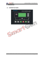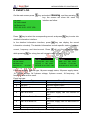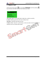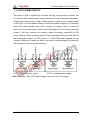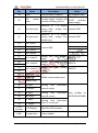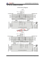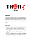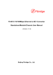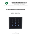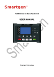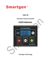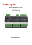
1
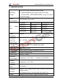
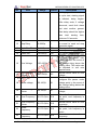
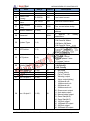
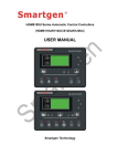
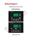
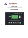
HAT600 Series
HAT600/HAT600I/HAT600B/HAT600BI
ATS CONTROLLER
USER MANUAL
ZHENGZHOU SMARTGEN TECHNOLOGY CO.,LTD
Chinese trademark
English trademark
Smartgen — make your generator smart
Smartgen Technology Co., Ltd.
No. 28 Jinsuo Road
Zhengzhou City
Henan Province
P. R. China
Tel: +86-371-67988888
+86-371-67981888
+86-371-67991553
+86-371-67992951
+86-371-67981000(overseas)
Fax: 0086-371-67992952
Web:
http://www.smartgen.com.cn/
http://www.smartgen.cn/
Email: [email protected]
All rights reserved. No part of this publication may be reproduced in any material
form (including photocopying or storing in any medium by electronic means or
other) without the written permission of the copyright holder.
Smartgen Technology reserves the right to change the contents of this document
without prior notice.
If colors of actual products are different from those mentioned within this manual,
please take the actual product as the standard.
Version history
Version
Date
1.0
2009-11-30
1.1
2010-04-07
1.2
2010-06-20
1.3
2010-06-30
Note
Original release.
Revise front mask
Modify instruction format and panel cutout size.
Add the clock and schedule start function.
1.4
1.5
1.6
1.7
1.8
1.9
2.0
2010-07-05
2011-04-08
2011-09-02
2012-03-02
Add type instruction of HAT600 series.
Modify cycle start functions.
Add description of current function
Change company name into “Smartgen Technology”;
Add trademark description
2012-09-01 Add functional description; modify some parameters;
add event log description.
2013-11-21 Modify some details.
2014-12-15 Add “Breaker Wiring Diagram”.
This manual is suitable for HAT600 series ATS controller only.
Clarification of notation used within this publication.
SIGN
INSTRUCTION
Note
Highlights an essential element of a procedure to ensure
correctness.
Indicates a procedure or practice, which, if not strictly
Caution!
observed, could result in damage or destruction of equipment.
Warning!
Indicates error operation may cause death, serious injury and
significant property damage.
HAT600 SERIES ATS CONTROLLER
CONTENT
1
OVERVIEW .................................................................................................... 5
2
PERFORMANCE AND CHARACTERISTICS ................................................ 6
3
SPECIFICATION ............................................................................................ 8
4
OPERATING .................................................................................................. 9
4.1 OPERATION PANEL ................................................................................ 9
4.2 KEY FUNCTION DESCRIPTION ............................................................ 10
5
LCD DISPLAY .............................................................................................. 11
5.1 MAIN SCREEN ....................................................................................... 11
5.2 MAIN MENU INTERFACE ...................................................................... 14
6
COMMISSIONING ........................................................................................ 15
7
PARAMETERS CONFIGURATION .............................................................. 16
7.1 PARAMETERS TABLE ........................................................................... 17
7.2 INPUT/OUTPUT FUNCTION DESCRIPTION ........................................ 21
8
EVENT LOG ................................................................................................. 23
9
TIMING START ............................................................................................ 24
10
DATE AND TIME SETTING ...................................................................... 25
11
LANGUAGE SETTING .............................................................................. 26
12
CONTROLLER INFORMATION ................................................................ 27
13
ATS OPERATION ..................................................................................... 28
13.1 MANUAL OPERATION ........................................................................... 28
13.2 AUTOMATIC OPERATION ..................................................................... 28
13.3 ATS POWER SUPPLY ............................................................................ 29
14
COMMUNICATION CONFIGURATION .................................................... 30
15
DESCRIPTION OF CONNECTING TERMINALS...................................... 31
16
TYPICAL WIRING DIAGRAM.................................................................... 33
17
INSTALLATION ......................................................................................... 37
18
FAULT FINDING ....................................................................................... 38
HAT600 SERIES ATS CONTROLLER
2014-12-15
Version 2.0
Page 4 of 38
HAT600 SERIES ATS CONTROLLER
1 OVERVIEW
HAT600
series
ATS
controller
is
intelligent
dual-supply
module
with
programmable function, automatic measurement, LCD display, and digital
communication. It combines digital intelligence and networking. Automatic
measurement and control can reduce incorrect operation. It is an ideal option for
ATS.
HAT600 series ATS controller is made of microprocessor as its core, can
accurately detect extended-spectrum 2-way-3-phase voltage and also make
accurate judgment and output passive control switch under the abnormal voltage
(over and under voltage, miss phase and over and under frequency). This
controller has full consideration in various application of ATS (automatic transfer
system) can be directly used for Intelligent ATS, Contactor ATS, Circuit Break ATS
etc. It have compact structure, advanced circuits, simple wiring and high reliability,
be widely used in electric power, telecommunications, petroleum, coal, metallurgy,
railways, municipal administration, intelligent building, electrical devices,
automatic control and testing system etc.
HAT600 SERIES ATS CONTROLLER
2014-12-15
Version 2.0
Page 5 of 38
HAT600 SERIES ATS CONTROLLER
2 PERFORMANCE AND CHARACTERISTICS
◙ System type can set for: Mains (1#) & Mains (2#), Mains (1#) & Generator
(2#), Generator (1#) & Mains (2#), Generator (1#) & Generator (2#).
◙ Backlit 128x64 LCD, optional Chinese and English display, push-button
operation.
◙ Measure and display 2-way 3 phase Voltage and Frequency:
1#
2#
Line-Line voltage (Uab, Ubc, Uca)
Line-Line voltage (Uab, Ubc, Uca)
Line-Nature voltage (Ua, Ub, Uc)
Line-Nature voltage (Ua, Ub, Uc)
Frequency (F1)
Frequency (F2)
◙ Measure and display active power, apparent power, power factor and 3
phase current;
◙ Over current alarm;
◙ Over/under voltage, loss of phase, reverse phase sequence, over/under
frequency protection.
◙ Automatic/Manual mode. In manual mode, can force switch to close or open;
◙ All parameters can be set on site. With Two different passwords which
ensures authorized staff operation only.
◙ During genset testing ATS controller can be set either on On-load or Off-load
mode.
◙ ATS Controller has function of automatic Re-closing.
◙ Closing output signal can be set as on intervals or as continuous output.
◙ Applicable for ATS of one neutral position, two neutral position and change
over.
◙
◙
◙
◙
Applicable for 2 isolated neutral line for Generator and Mains.
Real-time clock (RTC).
Event log can record 99 items circularly.
Timely schedule can be set on monthly or weekly basis and trial can be set
as with on- load or off -load.
◙ Can control two generators to work in a cycle, even the genset running time
and crank rest time can be set.
◙ Widely range of DC power supply (8V to 35V). Max.80V DC input can be
endured in an instant, or be supplied via HWS560 module (input AC
85V~560V, output DC 12V).
HAT600 SERIES ATS CONTROLLER
2014-12-15
Version 2.0
Page 6 of 38
HAT600 SERIES ATS CONTROLLER
◙ Wide space between connecting terminals of AC input. Max.625V input
voltage.
◙ With standard isolated RS485 communication interface. With "remote
controlling, remote measuring, remote communication" function by the
ModBus communication protocol.
◙ Can check the current status of controller (including switch digital input, over
Voltage, and under Voltage etc.).
◙ Suitable for various AC systems (3 phase 4-wires, 3-phase 3-wires,
single-phase 2-wire, and 2-phase 3-wire).
◙ Modular design, flame-resisting ABS plastic shell, plug-in terminals and
embedded installation. Compact structure with easy installation.
HAT600 series controller and its main functions are shown as following,
Function
DC Power
AC Power
Supply
Supply
HAT600
√
×
×
HAT600I
√
×
√
HAT600B
√
√ (LN220V)
×
HAT600BI
√
√ (LN220V)
√
AC Current Sample
Type
HAT600 SERIES ATS CONTROLLER
2014-12-15
Version 2.0
Page 7 of 38
HAT600 SERIES ATS CONTROLLER
3 SPECIFICATION
1. DC 8.0V~35.0V, continuous power supply.
Operating
2. HTS220/HWS560 power supply (without DC input).
Voltage
3. AC160V~280V (HAT600B/HAT600BI) during AC power
L1N1/L2N2 supply.
Power
Consumption
AC
Voltage
Input
Rated
<3W (Standby mode: ≤2W)
AC system
HAT600/HAT600I HAT600B/HAT600BI
3P4W (L-L)
(80~625)V
(80~480)V
3P3W (L-L)
(80~625)V
Not used
1P2W (L-N)
(50~360)V
(50~280)V
2P3W (A-B)
(80~625)V
(80~480)V
50/60Hz
Frequency
Close And
Open Trip
16A AC250V
Free Voltage relay output
Relay Output
Programmable
Relay Output
Digital Input
16A/7A AC250V
Free Voltage relay output
Connecting to GND
Communication RS485 isolated interface, MODBUS Protocol
Dimensions
209mmx153mmx55mm
Panel Cutout
186mm x 141mm
Operating
Temp. Range
Storage
Condition
Protection
Rank
Temperature: (-25~+70)°C;
Humidity: (20~93)%RH
Temperature: (-25~+70)°C
IP55 Gasket
Insulation
Apply AC2.2kV voltage between high voltage terminal and low
voltage terminal;
Strength
The leakage current is not more than 3mA within 1min.
Weight
0.8kg(HAT600,HAT600I)/1.0kg(HAT600B/HAT600BI)
HAT600 SERIES ATS CONTROLLER
2014-12-15
Version 2.0
Page 8 of 38
HAT600 SERIES ATS CONTROLLER
4 OPERATING
4.1 OPERATION PANEL
HAT600 SERIES ATS CONTROLLER
2014-12-15
Version 2.0
Page 9 of 38
HAT600 SERIES ATS CONTROLLER
4.2 KEY FUNCTION DESCRIPTION
I# Close
In Manual mode, switch on 1# power to load.
In Manual mode, switch off 1# or 2# power to
Open
off-load.
II# Close
In Manual mode, switch on 2# power to load.
Manual
Press and controller enter into Manual mode.
Automatic
Press and controller enter into AUTO mode.
Pressing this key can directly enter commissioning
Test
interface.
Press the key to enter menu interface; pressing and
Menu /
holding it to return to the main menu interface.
Confirm
When an alarm occurs, pressing and holding the
key can remove alarm.
Scroll Screen
Scroll the screen.
/Increase
this key can increase values.
HAT600 SERIES ATS CONTROLLER
2014-12-15
In parameter editing, pressing
Version 2.0
Page 10 of 38
HAT600 SERIES ATS CONTROLLER
5 LCD DISPLAY
5.1 MAIN SCREEN
U1(L-L) 380 380 380V
U2(L-L) 380 380 380V
F1 50.0Hz F2 50.0Hz
Present Status: MANUAL
This screen shows:
line-line voltage
(L1-L2, L2-L3, and L3-L1), frequency and
controller’s present working mode.
U1(L-N) 219 219 219V
U2(L-N) 219 219 219V
2010-06-10 (4) 20:25:36
Present Status: MANUAL
This screen shows: 1# and 2# 3 phase
Voltage (L-N), real-time clock and controller
working state.
AMP 500 500 500A
PWR
329kW
PF 1.00 PS 329kVA
Present Status: MANUAL
This screen show: 3 phase load current,
active power, apparent power, power factor
and controller working mode.
First line: 1# operating state of power
supply.
Second line: 2# operating state of power
supply.
Third line: other operating states.
Fourth line: alarm type and information.
1# Volt normal
2# Volt normal
Gens Start signal Out
Gens starting
Display priority of the #1 status (upper to lower)
No.
Item
Type
1
1# Gens Alarm
Alarm
2
1# Fail to Shut
Alarm
3
1# Fail to Break
off
Alarm
4
1# Over Voltage
Indication
5
1# Miss Phase
Indication
6
1# Over Freq
Indication
7
1# Below Freq
Indication
HAT600 SERIES ATS CONTROLLER
Description
When 1# genset occur failure, this
will display.
When 1# breaker occur closing
failure, this will display.
When 1# breaker occur opening
failure, this will display.
When 1# power supply voltage is
higher than the setting value, this will
display.
Loss of any phase of A, B and C.
When 1# power supply frequency is
higher than the setting value, this will
display.
When 1# power supply frequency is
lower than the setting value, this will
display.
2014-12-15
Version 2.0
Page 11 of 38
HAT600 SERIES ATS CONTROLLER
No.
Item
Type
8
1# Below Volt
Indication
9
1# reverse phase
Warning
10
1# Volt Normal
Indication
Description
When 1# power supply voltage is
lower than the setting value, this will
display.
Phase sequence is not A-B-C.
1# source voltage is within the setting
range.
Display priority of the #2 status (upper to lower)
No.
Item
Type
1
2# Gens Alarm
Alarm
2
2# Fail to Shut
Alarm
3
2# Fail to Break
off
Alarm
4
2# Over Volt
Indication
5
2# Miss Phase
Indication
6
2# Over Freq
Indication
7
2# Below Freq
Indication
8
2# Below Volt
Indication
9
2# reverse phase
Warning
10
2# Volt Normal
Indication
HAT600 SERIES ATS CONTROLLER
Description
When 2# genset occur failure, this will
display.
When 2# breaker occur closing failure,
this will display.
When 2# breaker occur opening
failure, this will display.
When 2# power supply voltage is
higher than the setting value, this will
display.
Loss of any phase of A, B and C.
When 2# power supply frequency is
higher than the setting value, this will
display.
When 2# power supply frequency is
lower than the setting value, this will
display.
When 2# power supply voltage is
lower than the setting value, this will
display.
Phase sequence is not A-B-C.
2# source voltage is within the setting
range.
2014-12-15
Version 2.0
Page 12 of 38
HAT600 SERIES ATS CONTROLLER
Display status of the other items(upper to lower)
No.
1
2
Item
Trip alarm
Breaking
compulsorily
Type
Alarm
Description
Trip alarm input is active.
Warning
3
Overload
Warning
4
Gens Start Out
Indication
5
Remote start input
Indication
Breaking compulsorily input is active.
Load current is over the setting limit
and exceed the setting delay.
Display that engine has been started.
This input is active when start the
genset circularly.
NOTE:
Alarm: When alarm occurs, indicators will flash and this alarm signal won’t be cut
until long pressing
to reset.
Warning: when warning occurs, alarm indicator will flash while extinguish when
warning alarm is inactive.
HAT600 SERIES ATS CONTROLLER
2014-12-15
Version 2.0
Page 13 of 38
HAT600 SERIES ATS CONTROLLER
5.2 MAIN MENU INTERFACE
In the screen, press
key, can enter the main menu interface.
1. Parameters set
2. History record
3. Time start
4. Date & Time Set
Press
key to choose parameters
(the current line was highlighted with
black) and then press
3. Time start
4. Date & Time Set
5. Language
6. Information
HAT600 SERIES ATS CONTROLLER
key to
confirm, can enter the corresponding
display screen.
2014-12-15
Version 2.0
Page 14 of 38
HAT600 SERIES ATS CONTROLLER
6 COMMISSIONING
On the main screen press
to enter into the operation interface, the screen will
show as following:
1 Exit
2 Stop to Test
3 Test Off-Load
4 Test On-Load
5 Cyc start
Press
key to select corresponding function, and press
key to confirm.
TEST OFF-LOAD: It will send out a start signal immediately. After generator is
normal, if mains is normal, the ATS will not act. The ATS will transfer the load to
generator only when mains is abnormal. After mains return normal, the ATS will
transfer the load to mains. Here the start generator signal output will keep.
TEST ON-LOAD: It will send out a start generator signal immediately. After
generator voltage is normal, the ATS will transfer the load to mains immediately
regardless whether the main is normal or not.
STOP TO TEST: The start generator signal will turn off after pressing this key
immediately.
CYCLE START: When this mode is active, generator start-signal will cyclic output
according to mains status. The cyclic time can be set by users. If generator fault
occurs, start-signal won’t be send out anymore by controller. If in manual mode,
controller will keep the current status and cancel cycle start function.
Conditions and procedures for cycle start mode:
1. In automatic mode.
2. Output setting: 1# engine start output (N/O Output) and 2 # engine start output
(N/O Output).
3. Input setting: 1# generator fault input, 2# generator fault input and remote start
input.
4. Option of <Cycle run times> and <Cycle shutdown times> should be
programmed and run.
5. Set the system type as 1# Gens & 2# Gens.
6. Set the proper <generator start delay> time.
Note: In manual mode, after choosing commissioning stage, generator will output
start-signal immediately, but the ATS will not transfer to load automatically except
for operation manually by pressing key on the front panel.
HAT600 SERIES ATS CONTROLLER
2014-12-15
Version 2.0
Page 15 of 38
HAT600 SERIES ATS CONTROLLER
7 PARAMETERS CONFIGURATION
In the main interface, press
press
key, choose 1.Parameters setting and then
key, to enter the password interface.
Input password value 0-9 by
key, and to shift Right by
key. Press the
again to confirm the password when Four number is OK. If password correct and
enter into the parameter mains interface. While error, directly exit and return to
main interface. Factory Default Password is 1234. Press
to shift to next
position and set the parameters. While setting the current configuration
parameters according to press
key. Then enter current parameter model,
and the current value of the first line screen display was highlighted with black.
Press
key to change the value while press
key to shift position, and
press
key again to confirm the password when Four number is OK. If the
value number is within the setting range, the value will be saved into the internal
memory of the controller; If it is beyond the range, then the parameters setting will
not be saved. Long time press
HAT600 SERIES ATS CONTROLLER
will back to the main display screen.
2014-12-15
Version 2.0
Page 16 of 38
HAT600 SERIES ATS CONTROLLER
7.1 PARAMETERS TABLE
Parameters item table
No.
Item
Range
Default
01
1# Normal Delay (0-9999)s
10
02
1#
Abnormal
(0-9999)s
Delay
5
03
2# Normal Delay (0-9999)s
10
04
2#
Abnormal
(0-9999)s
Delay
5
05
Close Breaker
(1-20)s
5
06
Open Breaker
(0-20)s
5
07
Transfer Interval
(0-9999)s
1
08
Exceed Transfer
(0-20.0)s
0.0
09
Again Shut Time
(0-20.0)s
1.0
10
Again Break
Time
(0-20.0)s
1.0
11
Start Delay
(0-9999)s
1
HAT600 SERIES ATS CONTROLLER
2014-12-15
Description
It is the delay of #1 power
from voltage abnormal to
voltage normal.
It is the delay of #1 power
from voltage normal to
voltage abnormal.
It is the delay of #2 power
from voltage abnormal to
voltage normal.
It is the delay of #2 power
from voltage normal to
voltage abnormal.
Closing relay output pulse. If
set as zero, it is continuous
output.
Opening relay output pulse.
It is the delay from 1# power
open to 2# power close or
from 2# power open to 1#
power close.
When module receives a
closing signal, closing relay
output.
When the breaker fail to
close for the first time, the
module will open breaker,
and then attempt to close for
the second time, if still failed
to close the second time, the
module will send out closing
breaker failure signal.
When the breaker fail to
open for the first time, the
module will close breaker,
and then attempt to open for
the second time, if still failed
to close the second time, the
module will send out opening
breaker failure signal.
When voltage is abnormal,
start delay begins and
Version 2.0
Page 17 of 38
HAT600 SERIES ATS CONTROLLER
No.
Item
Range
Default
Description
starting signal is initiated.
In cycle start, starting signal
is initiated, delay begins.
After delay ends, if voltage
abnormal, send fault alarm
and start another genset.
Start delay should be higher
than
12
Stop Delay
(0-9999)s
5
13
14
15
Cycle Run Time
Cycle Stop Time
Rated Volt
(1-1440)m
(1-1440)m
(100-600)V
720
720
230
16
Over Voltage
(100-150)%
120
17
Over Voltage
Return
(100-150)%
115
18
Under voltage
(50-100)%
80
19
Under Voltage
Return
(50-100)%
85
20
Over Frequency
(0.0-75.0)Hz
55.0
21
Over Frequency
Return
(0.0-75.0)Hz
52.0
22
Under
Frequency
(0.0-75.0)Hz
45.0
23
Under
Frequency
(0.0-75.0)Hz
48.0
HAT600 SERIES ATS CONTROLLER
2014-12-15
total
starting
time,
minimum 30 seconds.
It is the delay from #1 power
is normal to send out stop
generator signal.
Gens cycle start run time.
Gens cycle stop time.
AC system rated voltage.
The settings are used to
configure the power over
voltage point in the event of
the voltage rising above the
setting value. This value can
be adjusted to suit user
requirements.
Normal return value of over
voltage.
The settings are used to
configure the power under
voltage point in the event of
the voltage falling below the
setting value.
Normal return value of under
voltage.
When the frequency is over
the point, over frequency is
active.
Normal return value of over
frequency.
When the frequency is under
the point, low frequency is
active.
Normal return value of over
frequency.
Version 2.0
Page 18 of 38
HAT600 SERIES ATS CONTROLLER
No.
24
25
26
27
Item
Return
CT Rate
Rated Load
Current
Over Current
Value
Over Current
Delay
Range
Default
Description
(5-6000)/5
500
Current Transformer rate.
(5-5000)A
500
Load rated current.
(50-150)%
120
Load over current value.
(0-9999)s
1296
Over current alarm delay
(1-254)
1
28
Module Address
29
Password
30
System Type
(1-4)
1
31
Off Position
(1-3)
1
32
AC System
(1-4)
1
33
Priority Select
(1-3)
1
34
35
36
37
Aux. Output 1
Aux. Output 2
Aux. Output 3
Aux. Output 4
(1-28)
(1-28)
(1-28)
(1-28)
25
28
13
16
38
Aux. Output 5
(1-28)
18
1234
HAT600 SERIES ATS CONTROLLER
2014-12-15
RS485
communication
address
It
applies
to
modify
parameters.
1.1# Mains 2# Gens
2.1# Gens 2# Mains
3.1# Mains 2# Mains
4.1# Gens 2# Gens
1) two OFF position;
2) one OFF position;
3) no OFF position
1. 3-phase 4 wires
2. 3-phase 3 wires
3. Single phase 2 wire
4. 2-phase 3 wires
1. 1# Priority;
2. 2# Priority;
3. NO Priority
1 Not used
2 Critical failure
3 Fail of Transfer
4 Warning output
5 Alarm output(delay)
6 1# Normal volt
7 1# Abnormal volt
8 2# Normal volt
9 2# Abnormal volt
10 Overcurrent output
11 Auto state output
12 Manual state output
13 Gens Start(N/O)
14 Gens Start(N/C)
15 1# Shut output
16 1# Break Off output
17 2# Shut output
18 2# Break Off output
Version 2.0
Page 19 of 38
HAT600 SERIES ATS CONTROLLER
No.
39
40
41
42
Item
Range
Default
Aux. Input 1
Aux. Input 2
Aux. Input 3
(1-14)
(1-14)
(1-14)
02
01
01
Aux. Input 4
(1-14)
01
HAT600 SERIES ATS CONTROLLER
2014-12-15
Description
19 Common Alarm output
20 Time Test Gen Start
21 Shut state
22 2# Shut state
23 1# Gens Start(N/O)
24 2# Gens Start(N/O)
25 ATS Power L1
26 ATS Power L2
27 ATS Power L3
28 ATS Power N
01.Not used
02.Breaking compulsorily
03.Test off-load
04.Test on-load
05. Test Lamp
06. 1# Gens Alarm
07. 2# Gens Alarm
08. Remote start
09. Trip alarm
10. Reserved
11. Reserved
12. Reserved
13. Reserved
14. Reserved
Version 2.0
Page 20 of 38
HAT600 SERIES ATS CONTROLLER
7.2 INPUT/OUTPUT FUNCTION DESCRIPTION
The input port function as below,
Item
Description
1 Not used
Invalid.
When active, this will force the breaker to transfer the
2
Breaking
ATS to OFF position. “None OFF position” ATS is
compulsorily
unavailable
When active, controller will send a genset start signal
3 Test off-load
immediately. When mains is normal, gens will not
close the breaker.
When active, controller will send genset start signal
4 Test On-Load
immediately. When mains is normal, gens will close
the breaker.
When active, all Led lights on the front panel of the
5 Test lamp
controller will be bright and the background of the LCD
will be black in color.
In Cycle start, if the input is active, 1 # Gens will not
6 1# Gens Alarm
start
In Cycle start, if the input is active, 2 # Gens will not
7 2# Gens Alarm
start
8 Remote start
This input is necessary for cycle start generator.
9 Trip alarm
10 Reserved
11 Reserved
12 Reserved
13 Reserved
14 Reserved
HAT600 SERIES ATS CONTROLLER
2014-12-15
Version 2.0
Page 21 of 38
HAT600 SERIES ATS CONTROLLER
The output function as below,
Item
Description
1 Not used
2 Critical failure
3 Fail of transfer
4 Warning output
5 Alarm output (delay)
6 1# Normal volt
7 1# Abnormal volt
8 2# Normal volt
9 2# Abnormal volt
10 Over current output
11 Auto state output
12 Manual state output
13Gens start (N/O)
14Gens start (N/C)
15 1# shut output
16 1# break off output
17 2# shut output
18 2# break off output
19 Common alarm output
20 Time TestGen Start
21 1# Shut state
22 2# Shut state
23 1#Gens start (N/O)
24 2#Gens start (N/O)
25 ATS power L1
26 ATS power L2
27 ATS power L3
28 ATS power N
Switch transfer failure also belongs to the critical
failure alarm.
1# closed failure,1# open failure, 2# closed failure,
2# open failure also belongs to the fail to transfer.
1# reverse phase sequence; 2# reverse phase
sequence, and load over current and compulsory
belongs to general warning output.
When there is Serious fault then it will alarm for
60sec.
It will output when #1 voltage is normal.
It will output when #1 voltage is abnormal.
It will output when #2 voltages is normal.
It will output when #2 voltages is abnormal.
It will output when loaded current exceeds the
limit.
In will show output in automatic mode.
In will show output in manual mode.
When generator starts output (Relay closed).
When generator starts output (Relay released).
1# Switch ON signal output.
1# Switch OFF signal output, for one breaking
position breaks off output.
2# Switch ON signal output.
2# Switch OFF signal output.
It is include serious fault alarm and common alarm.
Schedulers start generator function.
#1 Switch auxiliary shutdown output.
#2 Switch auxiliary shutdown output.
1# Gens start output.
2# Gens start output.
ATS power supply.
HAT600 SERIES ATS CONTROLLER
2014-12-15
Version 2.0
Page 22 of 38
HAT600 SERIES ATS CONTROLLER
8 EVENT LOG
On the main screen press
key and select 2 Event log, and then pressing
key, the screen will show the event log
1# Shut
1# Volt normal
2# Below Volt
2010-02-18 21:15:07 1/99
Press
interface as follow:
key to select the corresponding record, and press
key to enter into
detailed information interface.
In the detailed information interface, press
key can display the record
information circularly. The detailed information include specific status of voltage,
current, frequency and time-to-event. Press
while pressing
will exit the current interface,
for a long time will return to main screen.
# 1 Shut
1# Volt normal
2# Below Volt
2010-02-18
21:15:07
1/20
#1 Shut
U1(L-N) 220 220 220V
U2(L-N) 0 100 220V
2010-02-18 21:15:07 1/99
#1 Shut
AMP 501 502 503A
F1 50.0Hz F2 50.1Hz
2010-02-18 21:15:07 1/99
Event log include:Record type, 1# power supply status, 2# power supply status,
1# 3-phase voltage, 2# 3-phase voltage, 3-phase current, 1# frequency, 2#
frequency and time-to-event.
Event log type:
NO.
Type
1
1# Shut
2
2# Shut
3
1# Fail to Shut
4
2# Fail to Shut
5
1# Fail to Break off
6
2# Fail to Break off
7
8
Trip alarm
Breaking compulsorily
HAT600 SERIES ATS CONTROLLER
Description
1# close signal output
2# close signal output
1# power supply can not connect
load.
2# power supply can not connect
load.
1# power supply can not disconnect
load.
2# power supply can not disconnect
load.
The input is active.
Breaking compulsorily input is active.
2014-12-15
Version 2.0
to
to
to
to
Page 23 of 38
HAT600 SERIES ATS CONTROLLER
9 TIMING START
On the main screen press
key and select 3 Time start, and then pressing
key, the screen will show the time start interface as follow:
1 Exit
2 Time start cyc
3 Load set
4 Start time
5 Continue time
Time start cycle: Include inhibit start; single time, weekly or monthly.
Load set: Starting generator with load or without load.
Start time: Generator start date and time.
Continue time: Generator continuously run time can be set on the duration of
maximum time for 99 hours 59 minutes.
HAT600 SERIES ATS CONTROLLER
2014-12-15
Version 2.0
Page 24 of 38
HAT600 SERIES ATS CONTROLLER
10 DATE AND TIME SETTING
On the main screen press
pressing
key and select 4 Date & Time set, and then
key, the screen will show the Date & Time Set interface as follow:
The Date Time Set
10-06-25 (2) 10:00
Press
key according to the corresponding bit input values 0-9, pressing
key to carry through the right of bit shift; pressing
key when right shift to the
end, can update the date and time.
Date and time format set: year-month-date (week) and hour: minute.
HAT600 SERIES ATS CONTROLLER
2014-12-15
Version 2.0
Page 25 of 38
HAT600 SERIES ATS CONTROLLER
11 LANGUAGE SETTING
On the main screen press
key and select 5 Language, press
again to
enter into language setting interface and the screen will show the language
interface as follow:
1.Simplified Chinese
2.English
Press
to select the language and press
to confirm the setting.
Language option:Simplified Chinese/ English
HAT600 SERIES ATS CONTROLLER
2014-12-15
Version 2.0
Page 26 of 38
HAT600 SERIES ATS CONTROLLER
12 CONTROLLER INFORMATION
On the main screen press
pressing
key and select 6 Controller information, and then
key, the screen will show the controller information interface as
follow:
Information
One OFF Position
1# Priority
Ver1.0
2009-10-11
Display content includes off positions setting and
switching priority choice and controller version, date.
Long pressing
key will exit and return to main screen.
HAT600 SERIES ATS CONTROLLER
2014-12-15
Version 2.0
Page 27 of 38
HAT600 SERIES ATS CONTROLLER
13 ATS OPERATION
13.1 MANUAL OPERATION
Press
key and manual operation indicator light, and the manual mode is
active.
● Press
, 1# close relay outputs immediately, if 1# closing input is active, its
indicator lights, and the 1# source connect to load.
● Press
, 2# close relay outputs immediately, if 2# closing input is active, its
indicator lights, and the 2# source connect to load.
● Press
, 1# or 2# open relay outputs immediately, if 1# or 2# closing input is
inactive, the indicators is black, the 1# or 2# power disconnect with load. *1
Note
*1: For the ATS of no OFF position, pressing
key is invalid.
13.2 AUTOMATIC OPERATION
Press
and the automatic LED will light, enter AUTO mode and controller can
automatically switch load to 1# or 2#.
HAT600 SERIES ATS CONTROLLER
2014-12-15
Version 2.0
Page 28 of 38
HAT600 SERIES ATS CONTROLLER
13.3 ATS POWER SUPPLY
The power of ATS is supplied by controller, as long as one power is normal, this
can ensures ATS voltage power supply normally and can be transferred properly.
Users should select power supply voltage (phase voltage or line voltage) based
on ATS type. If choose phase voltage, connect the phase voltage (A1) to normally
close (Pin5) and normally open (Pin7) contact of auxiliary output 1; connect N
phase (A1) to normally close (Pin8) and normally open (Pin10) contact of auxiliary
output 2. And then connect the common output of auxiliary output1&2 to ATS
power supplies. When controller power is ON, parameters can be set and also set
the configurable output1 as "ATS power L1". If the ATS power supplied by Line
Voltage, setting way is same as above, but need to change phase N to phase B.
Wiring diagrams are shown as following:
ATS L-N voltage power supply
ATS L-L voltage power supply
Note: Normally Close (N/C) input voltage must come from 1# voltage.
HAT600 SERIES ATS CONTROLLER
2014-12-15
Version 2.0
Page 29 of 38
HAT600 SERIES ATS CONTROLLER
14 COMMUNICATION CONFIGURATION
HAT600 series controller has RS485 serial port, can connect the local area
network openly. It uses Modbus protocol via PC or system software, it can also be
applicable to dual power switching management to factories, telecom, industrial
and civil buildings, which achieves “remote control, remote measuring, remote
communication” functions.
More information of Communication Protocol, refer to “HAT600 Communication
Protocol”.
Communication parameters,
Module address
1 (range: 1-254, User can set it)
Baud rate
9600 bps
Data bit
8bit
Parity bit
None
Stop bit
1 bit or 2-bits(set via PC)
HAT600 SERIES ATS CONTROLLER
2014-12-15
Version 2.0
Page 30 of 38
HAT600 SERIES ATS CONTROLLER
15 DESCRIPTION OF CONNECTING TERMINALS
Port functional description,
Pin
1
2
3
4
Items
Volt-free relay contact output
250V16A(relay
capacity)
2# close
output
Volt-free relay contact output
250V16A(relay
capacity)
NC
Aux. output 1
Default: ATS
power of L1
output.
Volt-free
contact
250V16A
relay
output:
Common
Default: ATS
power of N
Volt-free
contact
relay
output:
NO
output.
250V16A
Common
7
NO
8
NC
9
Notes
1# close
output
5
6
Description
Aux. output 2
10
11
A1
12
B1
13
C1
14
N1
15
A2
16
B2
17
C2
18
N2
1# AC 3-phase 4 wire voltage
input
For single phase,
only connect A1,
N1
2# AC 3-phase 4 wire voltage
input
For single phase,
only connect A2,
N2
HAT600 SERIES ATS CONTROLLER
2014-12-15
Version 2.0
Page 31 of 38
HAT600 SERIES ATS CONTROLLER
Pin
Items
19
GND
20
DC
input
21
22
power
1# close input
2# close input
Description
Notes
Connect battery negative
DC negative input
To start engine, connect the
terminal to battery positive
DC positive input
8-35V
controller
power supply
Detection of 1 # switch
closing state, voltage free
contact input
connect GND
Detection of 2 # switch
closing state, voltage free
connect GND
contact input
23
Aux. input 1
24
Aux. input 2
25
Aux. input 3
26
Aux. input 4
27
28
29
30
31
32
connect GND
Aux. output 3
Voltage free relay contact
output
250V7A
Aux. output 4
Voltage free relay contact
output
250V7A
Aux. output 5
Voltage free relay contact
output
250V7A
33
RS485 A+
34
RS485 B-
35
RS485 GND
36
IA Input
37
RS485 communication port
Secondary
IA Output
Sensing from
phase A current
38
IB Input
Sensing
Secondary
39
IB Output
phase B current
40
IC Input
41
IC Output
Sensing from Secondary
phase C current join
LCD
Contrast
LCD Display
Adjust the LCD contrast
LINK
Program port
Factory update
HAT600 SERIES ATS CONTROLLER
from
2014-12-15
Only
suitable
for
HAT600I/HAT600BI
Version 2.0
Page 32 of 38
HAT600 SERIES ATS CONTROLLER
16 TYPICAL WIRING DIAGRAM
ATYS3 Wiring Diagram
SGQ-N/T Wiring Diagram
HAT600 SERIES ATS CONTROLLER
2014-12-15
Version 2.0
Page 33 of 38
HAT600 SERIES ATS CONTROLLER
SGQ-M Wiring Diagram
VITZRO Wiring Diagram
HAT600 SERIES ATS CONTROLLER
2014-12-15
Version 2.0
Page 34 of 38
HAT600 SERIES ATS CONTROLLER
Contactor Wiring Diagram
ATYSM3S Wiring Diagram
HAT600 SERIES ATS CONTROLLER
2014-12-15
Version 2.0
Page 35 of 38
HAT600 SERIES ATS CONTROLLER
Breaker Wiring Diagram
NOTE: All above are application diagrams of HAT600 series ATS controllers.
However, HAT600 and HAT600B have no sample current input, please skip over
the current part of the diagram.
HAT600 SERIES ATS CONTROLLER
2014-12-15
Version 2.0
Page 36 of 38
HAT600 SERIES ATS CONTROLLER
17 INSTALLATION
HAT600 SERIES ATS CONTROLLER
2014-12-15
Version 2.0
Page 37 of 38
HAT600 SERIES ATS CONTROLLER
18 FAULT FINDING
Fault Symptom
Controller no
operation
RS485
communication
failure
Possible Remedy
Check the Phase A1, N1 or Phase A1, N1 voltage.
Check connection wirings from the controller to ATS.
Check DC fuse.
Check whether the RS485 is wrong connection between
negative and positive.
Check whether the RS485 adapt is abnormal.
Check whether the parameter settings in the module
addresses are incorrect.
If the above methods are no using, you can try to connect
the GND of controller with RS485 GND (or PC GND).
Recommend that the A and B lines of the 485 network
should be terminated at each end with a 120Ω resistor.
Programmable
output error
Check programmable output connections, pay attention to
Normally opened and closed.
Check the output parameters settings.
Ensure that the programmable input connect to GND
Programmable input reliably when it’s active, and hung up when it is inactive.
abnormal
(Note: The input will be possibly destroyed when
connected with voltage)
Check ATS.
Check the connection wirings between the controller and
ATS is not work while
the ATS.
Generator running
Ensure that the ATS OFF position numbers are same as
the setting OFF position numbers.
HAT600 SERIES ATS CONTROLLER
2014-12-15
Version 2.0
Page 38 of 38