1
OSCAT
BASIC:LIBRARY
Documentation In English
Version 3.33
Chapter
Table of Contents
1. Legal.................................................................................... 17
1.1.
1.2.
1.3.
1.4.
1.5.
Disclaimer................................................................................................................. 17
License Terms........................................................................................................... 17
Registered trademarks.............................................................................................. 17
Intended Use............................................................................................................. 18
Other........................................................................................................................ 18
2. Introduction.......................................................................... 19
2.1.
2.2.
2.3.
2.4.
2.5.
2.6.
Objectives................................................................................................................. 19
Conventions.............................................................................................................. 20
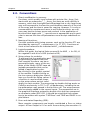
Test environment...................................................................................................... 21
Global constants....................................................................................................... 22
Releases................................................................................................................... 23
Support..................................................................................................................... 23
3. Data types of the OSCAT Library.............................................24
3.1. CALENDAR................................................................................................................ 24
3.2. COMPLEX.................................................................................................................. 25
3.3. CONSTANTS_LANGUAGE........................................................................................... 25
3.4. CONSTANTS_LOCATION............................................................................................. 26
3.5. CONSTANTS_MATH.................................................................................................... 26
3.6. CONSTANTS_PHYS..................................................................................................... 27
3.7. CONSTANTS_SETUP................................................................................................... 27
3.8. ESR_DATA.................................................................................................................. 28
3.9. FRACTION.................................................................................................................. 28
3.10. HOLIDAY_DATA........................................................................................................ 28
3.11. REAL2..................................................................................................................... 31
3.12. SDT......................................................................................................................... 31
3.13. TIMER_EVENT.......................................................................................................... 32
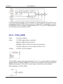
3.14. VECTOR_3............................................................................................................... 32
4. Other Functions .................................................................... 33
4.1.
4.2.
4.3.
4.4.
4.5.
4.6.
2
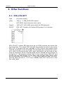
ESR_COLLECT........................................................................................................... 33
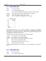
ESR_MON_B8............................................................................................................ 35
ESR_MON_R4............................................................................................................ 35
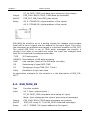
ESR_MON_X8............................................................................................................ 36
OSCAT_VERSION....................................................................................................... 37
STATUS_TO_ESR........................................................................................................ 38
Version 3.33
Chapter
5. Mathematics......................................................................... 39
5.1. ACOSH...................................................................................................................... 39
5.2. ACOTH...................................................................................................................... 39
5.3. AGDF......................................................................................................................... 39
5.4. ASINH........................................................................................................................ 40
5.5. ATAN2....................................................................................................................... 40
5.6. ATANH....................................................................................................................... 41
5.7. BETA......................................................................................................................... 41
5.8. BINOM....................................................................................................................... 42
5.9. CAUCHY.................................................................................................................... 42
5.10. CAUCHYCD.............................................................................................................. 43
5.11. CEIL......................................................................................................................... 43
5.12. CEIL2....................................................................................................................... 44
5.13. CMP......................................................................................................................... 44
5.14. COSH...................................................................................................................... 45
5.15. COTH...................................................................................................................... 45
5.16. D_TRUNC................................................................................................................ 46
5.17. DEC1....................................................................................................................... 46
5.18. DEG......................................................................................................................... 46
5.19. DIFFER.................................................................................................................... 47
5.20. ERF......................................................................................................................... 47
5.21. ERFC....................................................................................................................... 48
5.22. EVEN....................................................................................................................... 48
5.23. EXP10..................................................................................................................... 49
5.24. EXPN....................................................................................................................... 49
5.25. FACT........................................................................................................................ 49
5.26. FIB.......................................................................................................................... 50
5.27. FLOOR..................................................................................................................... 50
5.28. Floor2...................................................................................................................... 51
5.29. FRACT..................................................................................................................... 51
5.30. GAMMA................................................................................................................... 52
5.31. GAUSS..................................................................................................................... 52
5.32. GAUSSCD................................................................................................................ 53
5.33. GCD........................................................................................................................ 53
5.34. GDF......................................................................................................................... 54
5.35. GOLD...................................................................................................................... 54
5.36. HYPOT..................................................................................................................... 55
5.37. INC.......................................................................................................................... 55
5.38. INC1........................................................................................................................ 56
5.39. INC2........................................................................................................................ 56
5.40. INV.......................................................................................................................... 57
5.41. LAMBERT_W............................................................................................................ 58
5.42. LANGEVIN............................................................................................................... 58
5.43. MAX3...................................................................................................................... 59
5.44. MID3....................................................................................................................... 59
5.45. MIN3....................................................................................................................... 60
3
Version 3.33
Chapter
5.46.
5.47.
5.48.
5.49.
5.50.
5.51.
5.52.
5.53.
5.54.
5.55.
5.56.
5.57.
5.58.
5.59.
5.60.
5.61.
5.62.
5.63.
5.64.
5.65.
5.66.
MODR...................................................................................................................... 60
MUL_ADD................................................................................................................ 61
NEGX...................................................................................................................... 61
RAD......................................................................................................................... 61
RDM........................................................................................................................ 62
RDM2...................................................................................................................... 62
RDMDW................................................................................................................... 63
REAL_TO_FRAC........................................................................................................ 64
RND........................................................................................................................ 64
ROUND.................................................................................................................... 65
SGN......................................................................................................................... 65
SIGMOID.................................................................................................................. 66
SIGN_I..................................................................................................................... 66
SIGN_R.................................................................................................................... 67
SINC........................................................................................................................ 67
SINH........................................................................................................................ 67
SQRTN..................................................................................................................... 68
TANC....................................................................................................................... 68
TANH....................................................................................................................... 69
WINDOW................................................................................................................. 69
WINDOW2............................................................................................................... 69
6. Arrays..................................................................................71
6.1. _ARRAY_ABS.............................................................................................................. 71
6.2. _ARRAY_ADD............................................................................................................. 71
6.3. _ARRAY_INIT.............................................................................................................. 72
6.4. _ARRAY_MEDIAN........................................................................................................ 73
6.5. _ARRAY_MUL............................................................................................................. 73
6.6. _ARRAY_SHUFFLE...................................................................................................... 74
6.7. _ARRAY_SORT............................................................................................................ 75
6.8. ARRAY_AVG............................................................................................................... 76
6.9. ARRAY_GAV............................................................................................................... 76
6.10. ARRAY_HAV............................................................................................................. 77
6.11. ARRAY_MAX............................................................................................................. 77
6.12. ARRAY_MIN.............................................................................................................. 78
6.13. ARRAY_SDV............................................................................................................. 79
6.14. ARRAY_SPR.............................................................................................................. 79
6.15. ARRAY_SUM............................................................................................................. 80
6.16. ARRAY_TREND......................................................................................................... 81
6.17. ARRAY_VAR............................................................................................................. 81
6.18. IS_SORTED.............................................................................................................. 82
7. Complex Mathematics............................................................83
7.1. INTRODUCTION......................................................................................................... 83
4
Version 3.33
Chapter
7.2. CABS......................................................................................................................... 83
7.3. CaCO......................................................................................................................... 83
7.4. CACOSH.................................................................................................................... 84
7.5. CADD........................................................................................................................ 84
7.6. CARG........................................................................................................................ 84
7.7. CASIN........................................................................................................................ 85
7.8. CASINH..................................................................................................................... 85
7.9. CATAN....................................................................................................................... 86
7.10. CATANH................................................................................................................... 86
7.11. CCON...................................................................................................................... 86
7.12. CCOS....................................................................................................................... 87
7.13. CCOSH.................................................................................................................... 87
7.14. CDIV........................................................................................................................ 87
7.15. CEXP....................................................................................................................... 88
7.16. CINV........................................................................................................................ 88
7.17. CLOG....................................................................................................................... 88
7.18. CMUL...................................................................................................................... 89
7.19. CPOL....................................................................................................................... 89
7.20. CPOW...................................................................................................................... 89
7.21. CSET....................................................................................................................... 90
7.22. Csin......................................................................................................................... 90
7.23. CSINH...................................................................................................................... 90
7.24. CSQRT..................................................................................................................... 91
7.25. CSUB....................................................................................................................... 91
7.26. CTAN....................................................................................................................... 91
7.27. CTANH..................................................................................................................... 92
8. Arithmetics with Double Precision..........................................93
8.1.
8.2.
8.3.
8.4.
8.5.
8.6.
Introduction.............................................................................................................. 93
R2_ABS..................................................................................................................... 93
R2_ADD..................................................................................................................... 93
R2_ADD2................................................................................................................... 94
R2_MUL..................................................................................................................... 94
R2_SET...................................................................................................................... 95
9. Arithmetic Functions.............................................................96
9.1.
9.2.
9.3.
9.4.
9.5.
9.6.
9.7.
9.8.
5
F_LIN......................................................................................................................... 96
F_LIN2....................................................................................................................... 96
F_POLY...................................................................................................................... 97
F_POWER.................................................................................................................. 97
F_QUAD..................................................................................................................... 97
FRMP_B..................................................................................................................... 98
FT_AVG...................................................................................................................... 98
FT_MIN_MAX.............................................................................................................. 99
Version 3.33
Chapter
9.9. FT_RMP................................................................................................................... 100
9.10. LINEAR_INT........................................................................................................... 101
9.11. POLYNOM_INT........................................................................................................ 102
10. Geometric Functions.......................................................... 104
10.1.
10.2.
10.3.
10.4.
10.5.
10.6.
10.7.
10.8.
CIRCLE_A............................................................................................................... 104
CIRCLE_C............................................................................................................... 104
CIRCLE_SEG.......................................................................................................... 105
CONE_V................................................................................................................. 105
ELLIPSE_A............................................................................................................. 105
ELLIPSE_C............................................................................................................. 106
SPHERE_V............................................................................................................. 106
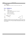
TRIANGLE_A.......................................................................................................... 107
11. Vector Mathematics........................................................... 108
11.1. Introduction.......................................................................................................... 108
11.2. V3_ABS................................................................................................................. 108
11.3. V3_ADD................................................................................................................. 108
11.4. V3_ANG................................................................................................................. 109
11.5. V3_DPRO............................................................................................................... 109
11.6. V3_NORM.............................................................................................................. 110
11.7. V3_NUL................................................................................................................. 110
11.8. V3_PAR.................................................................................................................. 110
11.9. V3_REV................................................................................................................. 111
11.10. V3_SMUL............................................................................................................. 111
11.11. V3_SUB............................................................................................................... 112
11.12. V3_XANG............................................................................................................. 112
11.13. V3_XPRO............................................................................................................. 112
11.14. V3_YANG............................................................................................................. 113
11.15. V3_ZANG............................................................................................................. 113
12. Time & Date...................................................................... 114
12.1. Introduction.......................................................................................................... 114
12.2. CALENDAR_CALC................................................................................................... 114
12.3. DATE_ADD............................................................................................................. 115
12.4. DAY_OF_DATE........................................................................................................ 116
12.5. DAY_OF_MONTH.................................................................................................... 116
12.6. DAY_OF_WEEK....................................................................................................... 117
12.7. DAY_OF_YEAR........................................................................................................ 117
12.8. DAY_TO_TIME........................................................................................................ 118
12.9. DAYS_DELTA.......................................................................................................... 118
12.10. DAYS_IN_MONTH................................................................................................. 119
6
Version 3.33
Chapter
12.11.
12.12.
12.13.
12.14.
12.15.
12.16.
12.17.
12.18.
12.19.
12.20.
12.21.
12.22.
12.23.
12.24.
12.25.
12.26.
12.27.
12.28.
12.29.
12.30.
12.31.
12.32.
12.33.
12.34.
12.35.
12.36.
12.37.
12.38.
12.39.
12.40.
12.41.
12.42.
12.43.
12.44.
12.45.
12.46.
12.47.
12.48.
12.49.
12.50.
12.51.
12.52.
12.53.
12.54.
12.55.
12.56.
7
DAYS_IN_YEAR..................................................................................................... 119
DCF77................................................................................................................. 119
DT2_TO_SDT....................................................................................................... 121
DT2_TO_SDT....................................................................................................... 121
DT_TO_SDT......................................................................................................... 122
EASTER............................................................................................................... 122
EVENTS............................................................................................................... 122
HOLIDAY.............................................................................................................. 123
HOUR.................................................................................................................. 124
HOUR_OF_DT...................................................................................................... 125
HOUR_TO_TIME................................................................................................... 125
HOUR_TO_TOD.................................................................................................... 125
JD2000................................................................................................................ 126
LEAP_DAY............................................................................................................ 126
LEAP_OF_DATE.................................................................................................... 127
LEAP_YEAR.......................................................................................................... 127
LTIME_TO_UTC..................................................................................................... 128
MINUTE............................................................................................................... 128
MINUTE_OF_DT.................................................................................................... 128
MINUTE_TO_TIME................................................................................................ 129
MONTH_BEGIN.................................................................................................... 129
MONTH_END....................................................................................................... 130
MONTH_OF_DATE................................................................................................ 130
MULTIME.............................................................................................................. 130
PERIOD................................................................................................................ 131
PERIOD2.............................................................................................................. 131
REFRACTION....................................................................................................... 132
RTC_2.................................................................................................................. 133
RTC_MS............................................................................................................... 134
SDT_TO_DATE..................................................................................................... 134
SDT_TO_DT......................................................................................................... 135
SDT_TO_TOD....................................................................................................... 135
SECOND.............................................................................................................. 135
SECOND_OF_DT.................................................................................................. 136
SECOND_TO_TIME............................................................................................... 136
SET_DATE............................................................................................................ 136
SET_DT................................................................................................................ 137
SET_TOD............................................................................................................. 138
SUN_MIDDAY....................................................................................................... 138
SUN_POS............................................................................................................. 138
SUN_TIME............................................................................................................ 139
TIME CHECK........................................................................................................ 141
UTC_TO_LTIME..................................................................................................... 142
WORK_WEEK....................................................................................................... 142
YEAR_BEGIN........................................................................................................ 143
YEAR_END........................................................................................................... 143
Version 3.33
Chapter
12.57. YEAR_OF_DATE.................................................................................................... 144
13. String Functions................................................................145
13.1. BIN_TO_BYTE......................................................................................................... 145
13.2. BIN_TO_DWORD.................................................................................................... 145
13.3. BYTE_TO_STRB...................................................................................................... 145
13.4. BYTE_TO_STRH...................................................................................................... 146
13.5. Capitalize.............................................................................................................. 146
13.6. CHARCODE............................................................................................................ 147
13.7. CHARNAME........................................................................................................... 147
13.8. CHR_TO_STRING................................................................................................... 148
13.9. CLEAN................................................................................................................... 149
13.10. CODE.................................................................................................................. 149
13.11. COUNT_CHAR...................................................................................................... 150
13.12. DEC_TO_BYTE...................................................................................................... 150
13.13. DEC_TO_DWORD................................................................................................. 150
13.14. DEC_TO_INT........................................................................................................ 151
13.15. DEL_CHARS......................................................................................................... 151
13.16. DT_TO_STRF........................................................................................................ 152
13.17. DWORD_TO_STRB............................................................................................... 153
13.18. DWORD_TO_STRF............................................................................................... 154
13.19. DWORD_TO_STRH............................................................................................... 154
13.20. EXEC................................................................................................................... 155
13.21. FILL..................................................................................................................... 155
13.22. FIND_CHAR......................................................................................................... 156
13.23. FIND_CTRL.......................................................................................................... 157
13.24. FIND_NONUM...................................................................................................... 157
13.25. FIND_NUM........................................................................................................... 157
13.26. FINDB.................................................................................................................. 158
13.27. FINDB_NONUM.................................................................................................... 158
13.28. FINDB_NUM......................................................................................................... 159
13.29. FINDP.................................................................................................................. 159
13.30. FIX...................................................................................................................... 160
13.31. FLOAT_TO_REAL.................................................................................................. 160
13.32. FSTRING_TO_BYTE............................................................................................... 161
13.33. FSTRING_TO_DT.................................................................................................. 161
13.34. FSTRING_TO_DWORD.......................................................................................... 162
13.35. FSTRING_TO_MONTH........................................................................................... 162
13.36. FSTRING_TO_WEEK............................................................................................. 163
13.37. FSTRING_TO_WEEKDAY....................................................................................... 164
13.38. HEX_TO_BYTE...................................................................................................... 164
13.39. HEX_TO_DWORD................................................................................................. 165
13.40. IS_ALNUM............................................................................................................ 165
13.41. IS_ALPHA............................................................................................................. 165
13.42. IS_CC................................................................................................................... 166
8
Version 3.33
Chapter
13.43.
13.44.
13.45.
13.46.
13.47.
13.48.
13.49.
13.50.
13.51.
13.52.
13.53.
13.54.
13.55.
13.56.
13.57.
13.58.
13.59.
13.60.
13.61.
13.62.
13.63.
13.64.
13.65.
13.66.
13.67.
13.68.
13.69.
13.70.
13.71.
13.72.
13.73.
13.74.
IS_CTRL............................................................................................................... 166
IS_HEX................................................................................................................ 167
IS_LOWER............................................................................................................ 167
IS_NCC................................................................................................................ 168
IS_NUM................................................................................................................ 168
IS_UPPER............................................................................................................. 169
ISC_ALPHA.......................................................................................................... 169
ISC_CTRL............................................................................................................. 170
ISC_HEX.............................................................................................................. 170
ISC_LOWER......................................................................................................... 171
ISC_NUM............................................................................................................. 171
ISC_UPPER.......................................................................................................... 172
LOWERCASE........................................................................................................ 172
MESSAGE_4R...................................................................................................... 173
MESSAGE_8......................................................................................................... 173
MIRROR............................................................................................................... 174
MONTH_TO_STRING............................................................................................ 175
OCT_TO_BYTE...................................................................................................... 175
OCT_TO_DWORD................................................................................................. 176
REAL_TO_STRF.................................................................................................... 176
REPLACE_ALL...................................................................................................... 177
REPLACE_CHARS................................................................................................. 177
REPLACE_UML..................................................................................................... 178
TICKER................................................................................................................ 178
TO_LOWER.......................................................................................................... 179
TO_UML............................................................................................................... 180
TO_UPPER........................................................................................................... 180
TRIM.................................................................................................................... 181
TRIM1.................................................................................................................. 181
TRIME.................................................................................................................. 181
UPPER CASE........................................................................................................ 182
WEEKDAY_TO_STRING......................................................................................... 182
14. Memory Modules...............................................................184
14.1.
14.2.
14.3.
14.4.
FIFO_16................................................................................................................. 184
FIFO_32................................................................................................................. 184
STACK_16.............................................................................................................. 185
STACK_32.............................................................................................................. 186
15. Pulse Generators............................................................... 188
15.1.
15.2.
15.3.
15.4.
9
A_TRIG..................................................................................................................
B_TRIG..................................................................................................................
CLICK_CNT............................................................................................................
CLICK_DEC............................................................................................................
188
188
189
190
Version 3.33
Chapter
15.5. CLK_DIV................................................................................................................ 190
15.6. CLK_N................................................................................................................... 192
15.7. CLK_PRG............................................................................................................... 192
15.8. CLK_PULSE............................................................................................................ 193
15.9. CYCLE_4................................................................................................................ 194
15.10. D_TRIG................................................................................................................ 195
15.11. GEN_BIT.............................................................................................................. 196
15.12. GEN_SQ............................................................................................................... 197
15.13. SCHEDULER........................................................................................................ 198
15.14. SCHEDULER_2..................................................................................................... 198
15.15. SEQUENCE_4....................................................................................................... 199
15.16. SEQUENCE_64..................................................................................................... 202
15.17. SEQUENCE_8....................................................................................................... 203
15.18. TMAX.................................................................................................................. 204
15.19. TMIN................................................................................................................... 205
15.20. TOF_1.................................................................................................................. 205
15.21. TONOF................................................................................................................ 206
15.22. TP_1.................................................................................................................... 207
15.23. TP_1D.................................................................................................................. 208
15.24. TP_X.................................................................................................................... 208
16. Logic Modules...................................................................210
16.1. BCDC_TO_INT........................................................................................................ 210
16.2. BIT_COUNT............................................................................................................ 210
16.3. BIT_LOAD_B........................................................................................................... 210
16.4. BIT_LOAD_B2......................................................................................................... 211
16.5. BIT_LOAD_DW....................................................................................................... 211
16.6. BIT_LOAD_DW2..................................................................................................... 212
16.7. BIT_LOAD_W.......................................................................................................... 212
16.8. BIT_LOAD_W2........................................................................................................ 213
16.9. BIT_OF_DWORD.................................................................................................... 213
16.10. BIT_TOGGLE_B.................................................................................................... 214
16.11. BIT_TOGGLE_DW................................................................................................. 214
16.12. BIT_TOGGLE_W................................................................................................... 215
16.13. BYTE_OF_BIT....................................................................................................... 215
16.14. BYTE_OF_DWORD................................................................................................ 216
16.15. BYTE_TO_BITS..................................................................................................... 216
16.16. BYTE_TO_GRAY.................................................................................................... 217
16.17. CHK_REAL........................................................................................................... 217
16.18. CHECK_PARITY.................................................................................................... 217
16.19. CRC_CHECK......................................................................................................... 218
16.20. CRC_GEN............................................................................................................. 219
16.21. DEC_2 ................................................................................................................ 222
16.22. DEC_4................................................................................................................. 222
16.23. DEC_8................................................................................................................. 223
10
Version 3.33
Chapter
16.24.
16.25.
16.26.
16.27.
16.28.
16.29.
16.30.
16.31.
16.32.
16.33.
16.34.
16.35.
16.36.
16.37.
16.38.
16.39.
16.40.
16.41.
16.42.
DW_TO_REAL...................................................................................................... 225
DWORD_OF_BYTE................................................................................................ 225
DWORD_OF_WORD............................................................................................. 226
GRAY_TO_BYTE.................................................................................................... 226
INT_TO_BCDC...................................................................................................... 227
MATRIX................................................................................................................ 227
MUX_2................................................................................................................. 229
MUX_4................................................................................................................. 229
PARITY................................................................................................................. 230
PIN_CODE............................................................................................................ 231
REAL_TO_DW...................................................................................................... 231
REFLECT.............................................................................................................. 232
REVERSE............................................................................................................. 232
SHL1................................................................................................................... 233
SHR1................................................................................................................... 233
SWAP_BYTE......................................................................................................... 234
SWAP_BYTE2....................................................................................................... 234
WORD_OF_BYTE.................................................................................................. 234
WORD_OF_DWORD............................................................................................. 235
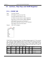
17. Latches, Flip-Flop and Shift Register................................... 236
17.1. COUNT_BR............................................................................................................ 236
17.2. COUNT_DR............................................................................................................ 237
17.3. FF_D2E.................................................................................................................. 238
17.4. FF_D4E.................................................................................................................. 239
17.5. FF_DRE.................................................................................................................. 240
17.6. FF_JKE................................................................................................................... 241
17.7. FF_RSE.................................................................................................................. 242
17.8. LTCH...................................................................................................................... 242
17.9. LATCH4................................................................................................................. 246
17.10. SELECT_8............................................................................................................ 247
17.11. SHR_4E............................................................................................................... 249
17.12. SHR_4UDE........................................................................................................... 250
17.13. SHR_8PLE............................................................................................................ 251
17.14. SHR_8UDE........................................................................................................... 252
17.15. STORE_8............................................................................................................. 253
17.16. TOGGLE.............................................................................................................. 254
18. Signal Generators.............................................................. 255
18.1.
18.2.
18.3.
18.4.
18.5.
11
_RMP_B.................................................................................................................
_RMP_NEXT...........................................................................................................
_RMP_W................................................................................................................
GEN_PULSE...........................................................................................................
GEN_PW2..............................................................................................................
255
255
256
257
258
Version 3.33
Chapter
18.6. GEN_RDM.............................................................................................................. 258
18.7. GEN_RDT............................................................................................................... 259
18.8. GEN_RMP.............................................................................................................. 260
18.9. GEN_SIN................................................................................................................ 261
18.10. GEN_SQR............................................................................................................ 262
18.11. PWM_DC.............................................................................................................. 263
18.12. PWM_PW............................................................................................................. 264
18.13. RMP_B................................................................................................................. 264
18.14. RMP_SOFT........................................................................................................... 266
18.15. RMP_W................................................................................................................ 267
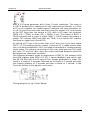
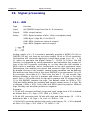
19. Signal processing..............................................................269
19.1. AIN........................................................................................................................ 269
19.2. AIN1...................................................................................................................... 270
19.3. AOUT..................................................................................................................... 271
19.4. AOUT1................................................................................................................... 272
19.5. BYTE_TO_RANGE................................................................................................... 273
19.6. DELAY................................................................................................................... 274
19.7. DELAY_4................................................................................................................ 275
19.8. FADE..................................................................................................................... 276
19.9. FILTER_DW............................................................................................................ 277
19.10. FILTER_I............................................................................................................... 278
19.11. FILTER_MAV_DW.................................................................................................. 278
19.12. FILTER_MAV_W.................................................................................................... 279
19.13. FILTER_W............................................................................................................. 280
19.14. FILTER_WAV......................................................................................................... 280
19.15. MIX...................................................................................................................... 281
19.16. MUX_R2.............................................................................................................. 281
19.17. MUX_R4.............................................................................................................. 282
19.18. OFFSET............................................................................................................... 282
19.19. OFFSET2............................................................................................................. 285
19.20. OVERRIDE........................................................................................................... 286
19.21. RANGE_TO_BYTE................................................................................................. 287
19.22. RANGE_TO_BYTE................................................................................................. 288
19.23. SCALE................................................................................................................. 288
19.24. SCALE_B.............................................................................................................. 289
19.25. SCALE_B2............................................................................................................ 290
19.26. SCALE _ B4.......................................................................................................... 291
19.27. SCALE_B8............................................................................................................ 292
19.28. SCALE_D............................................................................................................. 293
19.29. SCALE_R.............................................................................................................. 294
19.30. SCALE_X2............................................................................................................ 295
19.31. SCALE_X4............................................................................................................ 296
19.32. SCALE_X8............................................................................................................ 297
19.33. SEL2_OF_3.......................................................................................................... 298
12
Version 3.33
Chapter
19.34.
19.35.
19.36.
19.37.
19.38.
19.39.
19.40.
19.41.
19.42.
19.43.
SEL2_OF_3B........................................................................................................ 299
SH....................................................................................................................... 299
SH_1................................................................................................................... 300
SH_2................................................................................................................... 301
SH_T.................................................................................................................... 303
STAIR.................................................................................................................. 304
STAIR2................................................................................................................ 304
TREND................................................................................................................. 305
TREND_DW......................................................................................................... 315
WORD_TO_RANGE............................................................................................... 316
20. Sensors............................................................................. 317
20.1. MULTI_IN............................................................................................................... 317
20.2. RES_NI.................................................................................................................. 318
20.3. RES_NTC............................................................................................................... 319
20.4. RES_PT.................................................................................................................. 322
20.5. RES_SI................................................................................................................... 323
20.6. SENSOR_INT.......................................................................................................... 324
20.7. TEMP_NI................................................................................................................ 325
20.8. TEMP_NTC............................................................................................................. 326
20.9. TEMP_PT................................................................................................................ 326
20.10. TEMP_SI.............................................................................................................. 331
21. Measuring Modules............................................................ 333
21.1. ALARM_2............................................................................................................... 333
21.2. BAR_GRAPH.......................................................................................................... 333
21.3. CALIBRATE............................................................................................................ 337
21.4. CYCLE_TIME........................................................................................................... 338
21.5. DT_SIMU................................................................................................................ 338
21.6. FLOW_METER........................................................................................................ 339
21.7. M_D....................................................................................................................... 341
21.8. M_T....................................................................................................................... 342
21.9. M_TX..................................................................................................................... 342
21.10. METER................................................................................................................. 343
21.11. METER_STAT........................................................................................................ 345
21.12. ONTIME............................................................................................................... 346
21.13. T_PLC_MS............................................................................................................ 348
21.14. T_PLC_US............................................................................................................ 351
21.15. TC_MS................................................................................................................. 352
21.16. TC_S.................................................................................................................... 353
21.17. TC_US.................................................................................................................. 353
13
Version 3.33
Chapter
22. Calculations......................................................................354
22.1. ASTRO................................................................................................................... 354
22.2. BFT_TO_MS........................................................................................................... 354
22.3. C_TO_F.................................................................................................................. 356
22.4. C_TO_K.................................................................................................................. 356
22.5. DEG_TO_DIR.......................................................................................................... 356
22.6. DIR_TO_DEG.......................................................................................................... 360
22.7. ENERGY................................................................................................................. 361
22.8. F_TO_C.................................................................................................................. 361
22.9. F_TO_OM............................................................................................................... 362
22.10. F_TO_PT.............................................................................................................. 362
22.11. GEO_TO_DEG...................................................................................................... 362
22.12. K_TO_C................................................................................................................ 366
22.13. KMH_TO_MS........................................................................................................ 366
22.14. LENGTH............................................................................................................... 367
22.15. MS_TO_BFT......................................................................................................... 368
22.16. MS_TO_KMH........................................................................................................ 369
22.17. OM_TO_F............................................................................................................. 369
22.18. PRESSURE........................................................................................................... 371
22.19. PT_TO_F.............................................................................................................. 372
22.20. SPEED................................................................................................................. 372
22.21. TEMPERATURE..................................................................................................... 374
23. Control Modules................................................................376
23.1. Introduction.......................................................................................................... 376
23.2. BAND_B................................................................................................................. 377
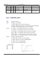
23.3. CONTROL_SET2..................................................................................................... 377
23.4. CONTROL_SET2..................................................................................................... 379
23.5. CTRL_IN................................................................................................................. 380
23.6. CTRL_OUT............................................................................................................. 381
23.7. CTRL_PI................................................................................................................. 382
23.8. CTRL_PID............................................................................................................... 384
23.9. CTRL_PWM............................................................................................................ 386
23.10. DEAD_BAND........................................................................................................ 387
23.11. DEAD_BAND_A.................................................................................................... 393
23.12. DEAD_ZONE........................................................................................................ 394
23.13. DEAD_ZONE2...................................................................................................... 395
23.14. FT_DERIV............................................................................................................. 396
23.15. FT_IMP................................................................................................................. 399
23.16. FT_INT................................................................................................................. 400
23.17. FT_INT2............................................................................................................... 402
23.18. FT_PD.................................................................................................................. 403
23.19. FT_PDT1.............................................................................................................. 403
23.20. FT_PI................................................................................................................... 404
14
Version 3.33
Chapter
23.21.
23.22.
23.23.
23.24.
23.25.
23.26.
23.27.
23.28.
23.29.
23.30.
23.31.
23.32.
23.33.
23.34.
23.35.
23.36.
23.37.
23.38.
23.39.
23.40.
23.41.
23.42.
23.43.
23.44.
23.45.
23.46.
23.47.
23.48.
23.49.
23.50.
23.51.
23.52.
23.53.
23.54.
23.55.
23.56.
23.57.
FT_PID................................................................................................................. 406
FT_PIDW.............................................................................................................. 407
FT_PIDWL............................................................................................................ 409
FT_PIW................................................................................................................ 411
FT_PIWL.............................................................................................................. 412
FT_PT1................................................................................................................ 414
FT_PT2................................................................................................................ 415
FT_TN16.............................................................................................................. 416
FT_TN64.............................................................................................................. 419
Ft_ TN8 ............................................................................................................... 420
HYST................................................................................................................... 421
HYST_1................................................................................................................ 422
HYST_2................................................................................................................ 424
HYST_3................................................................................................................ 425
INTEGRATE.......................................................................................................... 426
AIR_DENSITY....................................................................................................... 426
AIR_ENTHALPY.................................................................................................... 427
BOILER................................................................................................................ 428
BURNER.............................................................................................................. 430
DEW_CON........................................................................................................... 434
DEW_RH.............................................................................................................. 435
DEW_TEMP.......................................................................................................... 436
HEAT_INDEX........................................................................................................ 436
HEAT_METER....................................................................................................... 436
HEAT _TEMP........................................................................................................ 441
LEGIONELLA........................................................................................................ 443
SDD..................................................................................................................... 445
SDD_NH3............................................................................................................ 446
SDT_NH3............................................................................................................. 446
T_AVG24............................................................................................................. 446
TANK_VOL1......................................................................................................... 448
TANK_VOL2......................................................................................................... 448
TEMP_EXT........................................................................................................... 449
WATER_CP........................................................................................................... 452
WATER_DENSITY................................................................................................. 452
WATER_ENTHALPY............................................................................................... 453
WCT.................................................................................................................... 453
24. Device Driver..................................................................... 454
24.1.
24.2.
24.3.
24.4.
24.5.
24.6.
15
DRIVER_1.............................................................................................................. 454
DRIVER_4.............................................................................................................. 454
DRIVER_4C............................................................................................................ 455
FLOW_CONTROL.................................................................................................... 456
FT_PROFILE........................................................................................................... 457
INC_DEC................................................................................................................ 459
Version 3.33
Chapter
24.7. INTERLOCK............................................................................................................ 461
24.8. INTERLOCK_4........................................................................................................ 462
24.9. MANUAL................................................................................................................ 463
24.10. MANUAL_1.......................................................................................................... 464
24.11. MANUAL_2.......................................................................................................... 464
24.12. MANUAL_4.......................................................................................................... 465
24.13. Parset.................................................................................................................. 466
24.14. PARSET2............................................................................................................. 467
24.15. SIGNAL................................................................................................................ 468
24.16. SIGNAL_4............................................................................................................ 469
24.17. SRAMP................................................................................................................. 470
24.18. TUNE................................................................................................................... 472
24.19. TUNE2................................................................................................................. 475
25. BUFFER Management......................................................... 477
25.1.
25.2.
25.3.
25.4.
25.5.
25.6.
25.7.
25.8.
_BUFFER_CLEAR.................................................................................................... 477
_BUFFER_INIT........................................................................................................ 477
_BUFFER_INSERT................................................................................................... 478
_BUFFER_UPPERCASE............................................................................................ 479
_STRING_TO_BUFFER............................................................................................ 479
BUFFER_COMP...................................................................................................... 480
BUFFER_SEARCH................................................................................................... 481
BUFFER_TO_STRING.............................................................................................. 482
26. List Processing.................................................................. 484
26.1.
26.2.
26.3.
26.4.
26.5.
26.6.
26.7.
26.8.
26.9.
16
Introduction.......................................................................................................... 484
LIST_ADD.............................................................................................................. 484
LIST_CLEAN........................................................................................................... 485
LIST_GET............................................................................................................... 485
LIST_INSERT.......................................................................................................... 486
LIST_LEN............................................................................................................... 487
LIST_NEXT............................................................................................................. 487
LIST_RETRIEVE...................................................................................................... 488
LIST_RETRIEVE_LAST............................................................................................. 489
Version 3.33
Chapter 1.
Legal
1. Legal
1.1. Disclaimer
The software modules included in the OSCAT library are offered with the intent to
serve as a template and guideline for software development for PLC according to
IEC61131-3. A functional guarantee is not offered by the programmers and is
excluded explicitly. As the software modules included in the library are provided free
of charge, no warranty is provided to the extent permitted by law. As far as it is not
explicitly arranged in written form, the copyright owners and/ or third parties provide
the software modules “as is”, without any warranty, explicit or implicit, including, but
not limited to; market maturity or usability for a particular purpose. The full risk and
full responsibility concerning quality, absence of errors and performance of the
software module lie with the user. Should the library, or parts of it, turn out to contain
errors, the costs for service, repair and/or correction must be assumed by the user.
Should the entire library, or parts of it, be used to create user software, or be applied
in software projects, the user is liable for the absence of errors, performance and
quality of the application. Liability of OSCAT is explicitly ruled out.
The OSCAT library user has to take care, through suitable tests, releases and quality
assurance measures, that possible errors in the OSCAT library cannot cause
damage. The present license agreements and disclaimers are equally valid for the
software library, and the descriptions and explanations given in this manual, even
when this is not mentioned explicitly.
1.2. License Terms
The use of the OSCAT library is free of charge and it can be utilized for private or
business purposes. Distribution of the library is expressly encouraged; however, this
has to be free of charge and contain a reference to our webpage WWW.OSCAT.DE.
If the library is offered in electronic form for download or distributed on data carriers,
it has to be ensured that a clearly visible reference to OSCAT and a link to
WWW.OSCAT.DE are included accordingly.
1.3. Registered trademarks
All the trademarks used in this description are applied without reference to their
registration or owner. The existence of such rights can therefore not be ruled out. The
used trademarks are the property of their respective owners. Therefore, commercial
use of the description, or excerpts of it, is not permitted.
17
Version 3.33
Chapter 1.
Legal
1.4. Intended Use
The software modules included in the OSCAT library and described in this
documentation were exclusively developed for professionals who have had training in
PLC. The users are responsible for complying with all applicable standards and
regulations which come into effect with the use of the software modules. OSCAT
does not refer to these standards or regulations in either the manual or the software
itself.
1.5. Other
All legally binding regulations can be found solely in chapter 1 of the user manual.
Deduction or acquisition of legal claims based on the content of the manual, apart
from the provisions stipulated in chapter 1, is completely ruled out.
18
Version 3.33
Chapter 2.
Introduction
2. Introduction
2.1. Objectives
OSCAT is for " Open Source Community for Automation Technology ".
OSCAT created a Open Source Library referenced to the IEC61131-3 standard, which can be dispensed with vendor-specifc functions and therefore
ported to all IEC61131-3-compatible programmable logic controllers. Although trends for PLC in the use of vendor-specifc libraries are usually solved efciently and these libraries are also provided in part free of charge,
there are still major disadvantages of using it:
1. The libraries of almost all manufacturers are being protected and
the Source Code is not freely accessible, which is in case of a error
and correction of the error extremely difcult, often impossible.
2. The graphic development of programs with vendor-specifc libraries
can quickly become confusing, inefcient and error-prone, because
existing functions can not be adjusted and expanded to the actual
needs. The Source codes are not available.
3. A change of hardware, especially the move to another manufacturer, is prevented by the proprietary libraries and the benefts that a
standard such as IEC61131 ofer would be so restricted. A replacement of a proprietary library of a competitor is excluded, because
the libraries of the manufacturers difer greatly in scope and content.
4. The understanding of complex modules without an insight into the
source code is often very difcult. Therefore the programs are inefcient and error prone.
OSCAT will create with the open OSCAT Library a powerful and comprehensive standard for the programming of PLC, which is available in the
Source Code and verifed and tested by a variety of applications in detail.
Extensive knowledge and suggestions will continue to fow through a variety of applications to the library. Thus, the library can be described as
very practical. OSCAT understands his library as a development template
and not as a mature product. The user is solely responsible for the tests
in its application modules with the appropriate procedures and to verify
the necessary accuracy, quality and functionality. At this point we reference to the license and the disclaimer mentioned in this documentation.
19
Version 3.33
Chapter 2.
Introduction
2.2. Conventions
1. Direct modifcation in memory:
Functions, which modify input values with pointer like _Array_Sort,
starts with an underscore "_". _Array_Sort sorts an array directly in
memory, which has the signifcant advantage that a very large array
may not be passed to the function and therefore memory of the size
of the array and the time is saved for copying. However, it is only recommended for experienced users to use these functions, as a misuse may lead to serious errors and crashes! In the application of
functions that begin with "_", special care is appropriate and in particular to ensure that the call parameters never accept undefned values.
2. Naming of functions:
Function modules with timing manner, such as the function PT1 are
described by naming FT_<modulname> (ie. FT_PT1). Functions without a time reference are indicated with F_<modulename>.
3. Logical equations:
Within this guide, the logical links are used & for AND , + for OR, /A
for negated A and # for a XOR (exclusive OR).
4. Setup values for modules:
To achieve that the application and
programming remains clear and
that complex functions can be represented simply, many of the modules of the library OSCAT have adjustable parameters that can be
edited in application by double-clicking on the graphic symbol
of the module. Double-clicking on
the icon opens a dialog box that allows you to edit the Setup values. If
a function is used multiple times,
so the setup values are set individually for each module. The processing by double-clicking works on
CoDeSys exclusively in CFC. In ST, all parameters, including the setup parameters may passed in the function call. The setup parameters are simply added to the normal inputs. The parameters are in
the graphical interface entered by double click and then processed
as constants under IEC61131. It should be noted that time values
has to be written with syntax "T#200ms" and TRUE and FALSE in capital letters.
5. Error and status Reporting (ESR):
More complex components are largely contributed a Error or status
output. A Error Output is 0 if no error occurs during the execution. If,
20
Version 3.33
Chapter 2.
Introduction
however, in a module a error occurs, this output takes a value in the
range 1 ..99 and reports a error with a error number. A status or Error Collection module may collect these messages and time-stamped, store them in a database or array, or by TCP/IP forward it to
higher level systems. An output of the type Status is compatible
with a Error starting with identical function. However, a status output reports not only errors but also leads on activities of the module
log. Values between 1..99 are still error messages. Between
100..199 are located the reports of state changes. The range from
200..255 is reserved for Debug Messages. With this, within the library OSCAT standard functionality, a simple and comprehensive option
is ofered to integrate operational messages and error messages in
a simple manner, without afecting the function of a system. Modules that support this procedure, as of revision 1.4 are marked "ESRready." For more information on ESR modules, see the section
"Other functions".
2.3. Test environment
The OSCAT library is designed with CoDeSys and tested on diferent systems.
The test environment consists of the following systems:
1. Beckhof BX 9000
with TwinCAT PLC Control Version 2.10.0
2. Beckhof CX 9001-1001
with TwinCAT PLC Control Version 2.10.0
3. Wago 750-841
with CoDeSys Version 2.3.9.31
4. Möller EC4P222
with CoDeSys Version 2.3.9.31
5. CoDeSys Simulation on I386 CoDeSys 2.3.9.31
6. CoDeSys Simulation on I386 CoDeSys 3.4
7. S7 and STEP 7: The OSCAT library is compiled and verifed on STEP7
since version 1.5.
8. PCWORX / MULTIPROG: The OSCAT library since version 2.6 compiled
on MULTIPROG and verifed.
9. Bosch Rexroth IndraLogic XLC L25/L45/L65 with Indraworks 12VRS
10.Bosch Rexroth IndraMotion MLC L25/L45/L65 with Indraworks 12VRS
11.Bosch Rexroth IndraMotion MTX L45/L65/L85 with Indraworks 12VRS
21
Version 3.33
Chapter 2.
Introduction
We are constantly striving OSCAT the library to also test in other test environments.
2.4. Global constants
OSCAT The library tries to avoid global variables, an attempt to be easily
integrated into other environments. Global variables are not necessary for
function and exchange of data between devices. The setup and confguration is fully implemented within the modules to ensure high modularity
and portability. For physical and mathematical constants we decided for
reasons of clarity to use global constants.
MATH :
MATH defned mathematical constants. The constants are defned in the
TYPE defnition CONSTANTS_MATH.
PHYS :
PHYS defnes physical constants. The constants are defned in the TYPE
defnition CONSTANTS_PHYS.
LANGUAGE :
LANGUAGE defnes language. The settings are defned in the TYPE defnition CONSTANTS_LANGUAGE.
SETUP :
SETUP defnes general basic settings. The settings are defned in the TYPE
defnition CONSTANTS_SETUP.
LOCATION :
LOCATION defnes location settings, including but also defnitions holiday.
The settings are defned in the TYPE defnition CONSTANTS_LOCATION.
String_Length : INT: = 250
String_Length is by default 250 characters, and is used by STRING function to avoid a range overfow when processing STRINGS. STRING_LENGTH
shall also determine within the OSCAT LIB the maximum length, which can
lead to high memory consumption when heavily used. If in a Application
short STRINGS must be processed, the length may be reduced accordingly
on these SETUP constant STRING. We recommend to defne STRINGS wi22
Version 3.33
Chapter 2.
Introduction
thin the application with the aid of this constant. STRINGS, if longer than
80 characters, may need to increase this constant at a value to 255.
New_string: STRING(String_Length).
WIth this defnition the newly defned STRING automatically defnes the
length of STRING_LENGTH and can be changed globally if needed.
LIST_LENGTH : INT := 250.
LIST_LENGTH is by default 250 characters and sets the size of lists.
2.5. Releases
This manual is updated by OSCAT continuously. It is recommended to download the latest version of the OSCAT manual under www.OSCAT.DE . Here
the most current Manual is available for download. In addition to the Manual OSCAT prepared a detailed revision history. The OSCAT revisionhistory
lists all revisions of individual modules, with amendments and at what release the library of this component is included.
2.6. Support
Support
is
given
by
the
users
in
the
forum
WWW.OSCAT.DE. A claim for support does not exists, even if the library or
parts of the library are faulty. The support in the forum under the OSCAT is
provided for users voluntarily and with each other. Updates to the library
and documentation are usually made available once a month on the home
page of OSCAT under WWW.OSCAT.DE. A claim for maintenance, troubleshooting and software maintenance of any kind is generally not existing
from OSCAT. Please do not send support requests by email to OSCAT. Requests can be processed faster and more efectively when the inquiries
are made in our forum.
23
Version 3.33
Chapter 3.
Data types of the OSCAT Library
3. Data types of the OSCAT Library
Die OSCAT Bibliothek defniert neben den Standard Datentypen weitere
Datentypen. Diese werden innerhalb der Bibliothek verwendet, können
aber jederzeit von Anwender für eigene Deklarationen verwendet werden.
Ein Löschen oder verändern von Datentypen kann dazu führen das Teile
der Bibliothek sich nicht mehr kompilieren lassen.
3.1. CALENDAR
A variable type CALENDAR can be used for to provide modul wide calendar
data. In the section date and time functions are various functions to update the calendar continuously.
24
*.UTC: DT
Universal world time
*.LDT: DT
Local time
*.LDate: DATE
Local date
*.LTOD: TOD
Local time of day
*.YEAR: INT
Local year
*.MONTH: INT
Local months
*.DAY: INT
Local days
*.WEEKDAY: INT
Local weekday
*.OFFSET: INT
nutes
Ofset of local time to universal time in mi-
*.DST_EN: BOOL
Daylight saving time Enable
*.DST_ON: BOOL
Daylight saving time is On
*.NAME: STRING (5)
Time zone name
*.LANGUAGE : INT
Language (See Language Setup)
*.LONGITUDE: REAL
Longitude of the place
*.LATITUDE: REAL
Latitude of the place
*.SUN_RISE: TOD
Time of sunrise (LTC)
*.SUN_SET: TOD
Time of sunset (LTC)
*.SUN_MIDDAY: TOD
south (LTC)
World time when the Sun stands in the
*.SUN_HEIGTH: REAL
zon
the highest altitude of the sun on the hori-
Version 3.33
Chapter 3.
Data types of the OSCAT Library
*.SUN_HOR: REAL
north
Horizontal solar altitude in degrees from
*.SUN_VER: REAL
zon
Vertical position of the sun above the hori-
*.NIGHT: BOOL
TRUE if night
*.HOLIDAY: BOOL
TRUE if holiday
*.HOLY_NAME : STRING (30)
Name of the holiday
*.WORK_WEEK: _ INT
current work week
3.2. COMPLEX
The COMPLEX structure can present complex numbers.
*.RE
( Real part of a complex number)
*.IM
Imaginary part of a complex number)
3.3. CONSTANTS_LANGUAGE
This structure defnes diferent languages as String Constants. The variable LANGUAGE of the global variables list provides itself in the library.
*. DEFAULT: INT: = 1 defnes the default Language
(1 = English, 2 = German, 3 = French)
The Default Language is always used when the language 0 is called. If the
language setting > 0 then the corresponding language is selected.
Language setting: 0 (the default language specifed in DEFAULTis used
(1 = English, 2 = German 3 = French)
other languages are defned by expanding the structure CONSTANTS_LANGUAGE.
*.LMAX: INT:= 3
specifes how many languages are available
*.WEEKDAYS: ARRAY[1..3, 1..7] OF STRING(10):= ' Monday','Tuesday'
'Wednesday','Thursday','Friday','Saturday','Sunday','Monday',
'Tuesday','Wednesday','Thursday','Friday','Saturday','Sunday';
*.WEEKDAYS2: ARRAY[1..3, 1..7] OF STRING(2):=
'Mo','Tu','We','Th','Fr','Sa','Su',
25
Version 3.33
Chapter 3.
Data types of the OSCAT Library
'Mo','Di','Mi','Do','Fr','Sa','So';
*.MONTHS: ARRAY[1..3, 1..12] OF STRING(10):= 'January','February',
'March','April','May','June','July','August','September','October',
ovember','December',
'N
'January','February','March','April','May','June','July','August',
'September','October','November','December';
*.MONTHS3:ARRAY[1..3, 1..12] OF STRING(3):=
'Jan','Feb','Mar','Apr','May','Jun','Jul','Aug','Sep','Oct','Nov','Dec',
'Jan','Feb','Mar','Apr','May','Jun','Jul','Aug','Sep','October','Nov','Dec';
*.DIRS:ARRAY[1..3,0..15] OF STRING(3):= 'N','NNE','NE','ENE','E',
'ESE','SE','SSE','S','SSW','SW','WSW','W','WNW','NW','NNW'
'N','NNE','NO','ENE','O','OSO','SO','SSO','S','SSW','SW','WSW'
'W','WNW','NW','NW';
3.4. CONSTANTS_LOCATION
This structure defnes location-dependent constants. The variable LOCATION of the global variable list places it in the library.
*.DEFAULT: INT:= 1
(1 = Germany, 2 = Austria, France 3 =, 4 = Belgium-German,
5 = Italy, South Tyrol).
*.LMAX: INT:= 3
indicates how many places are defned.
*.LANGUAGE : ARRAY[1..5] of INT := 2,2,3,2,2;
for each location, the language is defned.
3.5. CONSTANTS_MATH
This structure defnes mathematical constants. The variable MATH from
the global variables list places it in the library.
26
*.PI: REAL:= 3.14159265358
Circle number PI
*.PI2: REAL:= 6.28318530717
Circle number PI * 2
*.PI4: REAL:= 12.566370614359
Circle number PI * 4
*.PI05: REAL:= 1.5707963267949
Circle number PI / 2
Version 3.33
Chapter 3.
Data types of the OSCAT Library
*.PI025: REAL:= 0.785398163397448
Circle number PI / 4
*.PI_INV: REAL:= 0.318309886183791
1 / PI
*.E: REAL:= 2.718281828459045235
Euler's constant e
*.E_INV:= 0.367879441171442
1/e
*.SQ2: REAL:= 1.4142135623731
Root of 2
*.FACTS: ARRAY[0..12] of DINT
Faculties 0-12
3.6. CONSTANTS_PHYS
This structure defnes physical constants. The structure PHYS of the global
variable list places it in the library.
*.C: REAL:= 299792458
Speed of light in m/s
*.E: REAL:= 1.60217653E-19
Elementary charge in coulombs = A * s
*.G to REAL:= 9.80665
Gravitational acceleration in m / s ²
*.T0: REAL:= -273.15
absolute zero in °C
*.RU: REAL:= 8.314472
Universal gas constant in J / (mol * K)
*.PN: REAL:= 101325
Normal pressure Pa
3.7. CONSTANTS_SETUP
This structure defnes location-dependent constants. The variable SETUP
the global variables list places it in the library.
*.EXTENDED_ASCII: BOOL:= TRUE extends the ASCII character set to
special characters eg ÄÖÜ
*.CHARNAME[1..4]: STRING(253) stores Unicode character names
*.MTH_OFS: ARRAY[1..12] OF INT:= 0, 31, 59, 90, 120, 151, 181, 212,
243, 273, 304, 334;
MTH_OFS is used in various date functions, the array represents the respective current day ofset for the months of the year. The 1 February of a
year eg is the day 31 + 1
*.DECADES: ARRAY[0..8] OF REAL:= 1,10,100,1000,10000,100000,
1000000,10000000,100000000;
27
Version 3.33
Chapter 3.
Data types of the OSCAT Library
3.8. ESR_DATA
The structure ESR_DATA is used for Error and Status Reporting modules.
*.TYP : BYTE
Data Type
*.ADRESS : STRING(10)
Adress designation
*.DS : DT
Date / time stamp
*.TS : TIME
Timestamp in milliseconds
*.DATA : ARRAY[0..7] OF BYTE
Data packet
3.9. FRACTION
The data type FRACTION can be used to represent a fraction .
*.NUMERATOR : INT
Numerator of the fraction (numerator)
*.DENOMINATOR : INT
Denominator of the fraction (Denumerator)
3.10. HOLIDAY_DATA
The structure HOLIDAY_DATA is used to defne and describe holidays.
*.NAME : STRING(30)
Name of the holiday
*.DAY : SINT
Day of public holiday
*.MONTH : SINT
Month of the holy day
*.USE : SINT
activates the holyday (0=of, 1=on)
The structure is used by modules Calendar_calc and HOLYDAY by using a
array of type HOLYDAY_DATA for defnition of the annual holydays
There are 3 diferent types of defnitions:
Day 1-.31, MONTH 1..12, USE 1 (public holiday on a fxed date)
DAY ±X , MONTH, 0, USE 1 (holiday is X days before or after Easter)
Day 1..31, MONTH 1..12, USE -7 ..- 1 (public holiday on a weekday before
a date, herein is -1 Monday and -7 Sunday.
Examples:
28
Version 3.33
Chapter 3.
Data types of the OSCAT Library
(NAME:= 'New Year', Day:= 1, MONTH:= 1, USE:= 1) holiday with a fxed
date USE = 1 means it is active.
(NAME:= 'New Year', Day:= 1, MONTH:= 1, USE:= 1) holiday with a fxed
date USE = 0 means it is not active.
(NAME:= 'Karfreitag', DAY:= -2, MONTH:= 0, USE: = 1) holiday with a fxed
ofset from Easter Sunday, in this case, the Good Friday 2 days before Easter Sunday.
(NAME:= 'Buss und Bettag ", DAY:= 23, MONTH:= 11, USE: = -3) holiday
on the last Wednesday before the 23.11.yyyy of a year.
examples of holyday defnitions:
Array of Bavarian Holidays
HOLIDAY_DE: ARRAY [0..29] OF HOLIDAY_DATA:= (name:= 'New Year', day:= 1, month: = 1, use: = 1).
(Name:= 'Three Kings', Day:= 6, month:= 1 use:= 1),
(Name: = 'Good Friday', day:= -2, month: = 0, use: = 1),
(Name:= 'Easter Sunday', day:= 0, month:= 0, use:= 1),
(Name:= 'Easter Monday', day:= 1, month:= 0, use:= 1),
(Name:= 'Labor Day', day:= 1, month:= 5, use:= 1),
(Name:= 'Ascension', day:= 39, month:= 0, use:= 1),
(Name:= 'Pentecost', day:= 49, month:= 0, use:= 1)
(Name:= 'Easter Sunday', day:= 0, month:= 0, use:= 1)
(Name:= 'Corpus Christi', day:= 60, month:= 0, use:= 1)
(Name:= 'Peace of Augsburg', day:= 8, month:= 8, use:= 0)
(Name:= 'Assumption', day:= 15, month:= 8, use:= 1)
(Name:= 'Day of German Unity', day:= 3, month:= 10, use:= 1)
(Name:= 'Reformation', day:= 31, month:= 10, use:= 0)
(Name:= 'All Saints' Day:= 1, month:= 11, use:= 1)
(Name:= 'Buss und Bettag', day:= 23, month: = 11, use:= 0)
(Name:= '1. Christmas Day', day:= 25, month:= 12, use:= 1)
(Name:= '2. Christmas day ', day:= 26, month: = 12, use:= 1)
Array of Austrian Holidays
HOLIDAY_AT: ARRAY [0..29] OF HOLIDAY_DATA:= (name:= 'New Year', day:= 1, month:= 1, use:= 1).
(Name:= 'Three Kings', Day:= 6, month:= 1 use:= 1),
(Name: = 'Good Friday', day:= -2, month: = 0, use: = 1),
(Name:= 'Easter Sunday', day:= 0, month:= 0, use:= 1),
(Name:= 'Easter Monday', day:= 1, month:= 0, use:= 1),
(Name:= 'Ascension', day:= 39, month:= 0, use:= 1),
(Name:= 'Pentecost', day:= 49, month:= 0, use:= 1)
(Name:= 'Easter Sunday', day:= 0, month:= 0, use:= 1)
(Name:= 'Corpus Christi', day:= 60, month:= 0, use:= 1)
(Name: ='', day: = 8, month: = 8, use: = 0)
29
Version 3.33
Chapter 3.
Data types of the OSCAT Library
(Name:= 'Assumption', day:= 15, month:= 8, use:= 1)
(Name:='', day:= 3, month:= 10, use:= 0)
(Name:='', day:= 31, month:= 10, use:= 0)
(Name:= 'All Saints' Day:= 1, month:= 11, use:= 1)
(Name:= 'Immaculate Conception', day:= 8, month:= 12, use:= 1)
(Name:= '1. Christmas Day', day:= 25, month:= 12, use:= 1)
(Name:= '2. Christmas day ', day:= 26, month: = 12, use:= 1)
French Holidays
HOLIDAY_FR: ARRAY [0..29] OF HOLIDAY_DATA := (name: = 'Nouvel an', day:= 1, month:= 1, use:= 1)
(Name:= 'St Valentine', day:= 14, month:= 2, use:= 0)
(Name:= 'Vendredi Saint (alsace)', day:= -2, month:= 0, use:= 0)
(Name:= 'Dimanche de Pâques ", day:= 0, month:= 0, use:= 1)
(Name:= 'Lundi de Pâques', day:= 1, month:= 0, use:= 1)
(Name:= 'Jeudi de Ascension', day:= 39, month:= 0, use:= 1)
(Name:= 'dimanche de Pentecôte', day:= 49, month:= 0, use:= 1)
(Name:= 'jeudi de la Trinité', day:= 60, month:= 0, use:= 0)
(Name:= 'Fête du Travail ", day:= 1 month:= 5, use:= 1)
(Name:= 'Victoire 1945', day:= 8, month:= 5, use:= 1)
(Name:= 'Prise de la Bastille', day:= 14, month:= 7, use:= 1)
(Name:= '15 Août 1944 ', day:= 15, month:= 8, use:= 1)
(Name:= 'Halloween', day:= 31, month:= 10, use:= 0)
(Name:= 'Armistice 1918', day:= 11, month:= 11, use:= 1)
(Name:= 'Noël', day:= 25, month:= 12, use:= 1)
(Name:= 'Saint Etienne (Alsace)', day:= 26, month:= 12, use:= 0)
(Name:= 'Fête de la musique', day:= 21, month:= 6, use:= 0)
Belgium german language
HOLIDAY_BED: ARRAY [0..29] OF HOLIDAY_DATA:=
1)
(Name:= 'New Year', day:= 1, month:= 1, use:=
(Name:= 'Easter Sunday', day:= 0, month:= 0, use:= 1),
(Name:= 'Easter Monday', day:= 1, month:= 0, use:= 1),
(Name:= 'Labor Day', day:= 1, month:= 5, use:= 1),
(Name:= 'Ascension', day:= 39, month:= 0, use:= 1),
(Name:= 'Pentecost', day:= 49, month:= 0, use:= 1)
(Name:= 'Easter Sunday', day:= 0, month:= 0, use:= 1)
(Name:= 'national day', day:= 21, month:= 7, use:= 1)
(Name:= 'Assumption', day:= 15, month:= 8, use:= 1)
(Name:= 'All Saints' Day:= 1, month:= 11, use:= 1)
(Name:= 'DG holiday', day:= 15, month:= 11, use:= 1)
(Name:= 'Christmas Eve', day:= 24, month:= 12, use:= 1)
(Name:= '1. Christmas Day', day:= 25, month:= 12, use:= 1)
(Name:= '2. Christmas day ', day:= 26, month: = 12, use:= 1)
(Name:= 'New Year', day:= 31, month:= 12, use:= 1);
30
Version 3.33
Chapter 3.
Data types of the OSCAT Library
South Tyrol, italy
HOLIDAY_DE: ARRAY [0..29] OF HOLIDAY_DATA:= (name:= 'New Year', day:= 1, month:= 1, use:= 1).
(Name:= 'Three Kings', Day:= 6, month:= 1 use:= 1),
(Name:= 'Easter Sunday', day:= 0, month:= 0, use:= 1),
(Name:= 'Easter Monday', day:= 1, month:= 0, use:= 1),
(Name:= 'tday to be exempted in Italy', day:= 25, month:= 4, use:= 1)
(Name:= 'Labor Day', day:= 1, month:= 5, use:= 1),
(Name:= 'Pentecost', day:= 49, month:= 0, use:= 1)
(Name:= 'Easter Sunday', day:= 0, month:= 0, use:= 1)
(Name:= 'Day of the Republic of Italy', day:= 2, month:= 6, use:= 1)
(Name:= 'Assumption', day:= 15, month:= 8, use:= 1)
(Name:= 'All Saints' Day:= 1, month:= 11, use:= 1)
(Name:= 'Immaculate Conception', day:= 8, month:= 12, use:= 1)
(Name:= 'Christmas Eve', day:= 24, month:= 12, use:= 1)
(Name:= '1. Christmas Day', day:= 25, month:= 12, use:= 1)
(Name:= '2. Stephen day', day:= 26, month:= 12, use:= 1); *)
3.11. REAL2
The structure of REAL2 simulates on systems without LREAL a foating
point value double precision. but with restrictions and only with special
functions.
*.R1 : REAL
Roughly double the number of
*. RX: REAL
Fine part of the double number
3.12. SDT
The structure for SDT defnes a structured time-date format.
31
*.YEAR: INT
Year
*.MONTH: INT
Month
*. DAY: IN T
Day
WEE *. KDAY: INT
Week (1 = Monday, 7 = Sunday)
*. HOUR: INT
Hours
*. MINUTE: INT
Minutes
*. SECOND: INT
Seconds
Version 3.33
Chapter 3.
Data types of the OSCAT Library
*. MS: INT
Milliseconds
3.13. TIMER_EVENT
The structure TIMER_EVENT defnes and stores defaults for timers and
events.
*.TYP : BYTE
Event Type
*.CHANNEL : BYTE
Channel
*.DAY : BYTE
Day or days
*.START : TOD
Start time
*.DURATION : TIME
Duration
*.LAND : BYTE
Logical AND
*.LOR : BYTE
Logical OR
*.LAST : DT
last activity of the event
3.14. VECTOR_3
The Structure VECTOR_3 stores the three vectors of a three-dimensional
vector space.
32
*.X : REAL
component in x direction
*.Y : REAL
Component in Y - direction
*.Z : REAL
Component in Z - direction
Version 3.33
Chapter 4.
Other Functions
4. Other Functions
4.1. ESR_COLLECT
Type
Input
Function module
ESR_0.. 7: ESR_DATA (ESR inputs)
RST: BOOL (asynchronous reset input)
Output
IN/OUT
ESR_OUT : ESR_DATA (Array with the ESR protocol)
POS: INT ( Position of of latest ESR protocol in the array)
ESR_COLLECT collects ESR data from up to 8 ESR modules and stores the
log in an array. The output POS indicates the position at which in the array
ESR_OUT is currently the last message is ESR. Collects the module more
than 64 messages so the messages are discarded and restarted at position 0. With the asynchronous reset input, the device can be reset at any
time. By resetting, all the collected data will be deleted and the pointer is
moved to -1. The module collects data in the output array ESR_OUT and
moves POS the last position of the array that contains data. When there
are no messages POS remains to -1. If the output data are read, the variable POS has to be set to -1, or if only readed a part POS can be set to the
last valid value.
33
Version 3.33
Chapter 4.
Other Functions
The following example demonstrates how ESR_COLLECT is connected with
ESR modules.
The output ESR_OUT is made up as follows:
.
.ADRESS
TYPE
.DS
.TS
.DATA [0..7]
1
Label
Date
TIME
Status, 1 Byte
ESR Error
2
Label
Date
TIME
Status, 1 Byte
ESR Status
3
Label
Date
TIME
Status, 1 Byte
ESR Debug
10
Label
Date
TIME
not used
Boolean input low transition
11
Label
Date
TIME
not used
Boolean input high transition
20
Label
Date
TIME
Byte 0 - 3 Real Value
Real Value change
The ESR data includes the following:
34
ESR_DATA.TYP
Data type, see table above
ESR_DATA.ADRESS
up to 10 characters long String Identifer
ESR_DATA.DS
Date stamp of type TIME DATA
ESR_DATA.TS
Timestamp of type TIME (PLC Timer )
ESR_DATA.DATA
up to 8 bytes of data block
Version 3.33
Chapter 4.
Other Functions
4.2. ESR_MON_B8
Type
Function module
Input
S0..7: BOOL (signal input)
DT_IN: DATE_TIME (time-date-input stamp for time-stamp)
Output
ESR_FLAG: BOOL (TRUE, if ESR data are available)
IN/OUT
ESR_OUT: ESR_Data (ESR_data ouput)
Setup
A0..7: STRING(10) (designation of the inputs)
ESR_MON_B8 monitors up to 8 binary signals to change, and provides
them with a timestamp and a name. The collected messages are bufered
and passed to a protocol module on ESR_OUT. The output ESR_FLAG is set
to TRUE when messages are present.
The ESR data at the output consist of the following items:
.TYPE
11 rising edge , 10 falling edge
.ADRESS Byte address of ISR data recording
.LINE
Line number (input) of the ESR data recording
.DS
Date stamp of type DATE_TIME
.DT
Timestamp of type TIME (PLC- Timer )
.Data
Data block blank of 8 bytes
An application example for the module is in the description of ESR_COLLECT.
4.3. ESR_MON_R4
35
Type
Function module
Input
R0.. 3: REAL (signal input)
Version 3.33
Chapter 4.
Other Functions
DT_IN: DATE_TIME (time-date-input stamp for time-stamp)
Output
ESR_FLAG: BOOL (TRUE, if ESR data are available)
IN/OUT
ESR_OUT: ESR_Data (ESR_data ouput)
Setup
A0..3: STRING(10) (signal address of the inputs)
A0..3: STRING(10) (signal address of the inputs)
ESR_MON_R4 monitors up to 4 analog signals for changes and provides
them with a time s stamp and the address of the input signal. The collected messages are bufered and passed to a protocol module on ESR_OUT.
The output ESR_FLAG is set to TRUE when messages are present. A
change of an input is recorded only when the input has changed more
than the in threshold S predetermined value.
.TYPE
20 Floating point
.ADRESS Byte address of ISR data recording
.LINE
Line number (input) of the ESR data recording
.DS
Date stamp of type DATE_TIME
.DT
Timestamp of type TIME (PLC- Timer )
.Data
Data Block 4 byte real value
An application example for the module is in the description of ESR_COLLECT.
4.4. ESR_MON_X8
Type
Function module
Input
S0..7: Byte ( status Inputs )
DT_IN: DATE_TIME (time-date-time stamp for input)
Mode : Byte (designate the type of processing of messages)
Output
IN/OUT
Setup
36
ESR_FLAG: BOOL (TRUE when messages are present)
ESR_OUT: array [0..7] of ESR_DATA (collected messages)
A0..7: STRING (10) (signal address of the inputs)
Version 3.33
Chapter 4.
Other Functions
ESR_MON_X8 collects status messages of up to 8 ESR compatible modules, provides them with a Timestamp , date stamp , input number and a
module address. The collected messages are bufered and passed to a
protocol module. If messages for transmission are present, this is indicated by the signal ESR_FLAG. At input DT_IN the current time, which is used
for the timestamp of the messages should be provided. The MODE input
determines which status messages should be passed.
●
Mode = 1, only error messages are processed.
●
Mode = 2, status and error messages are processed.
●
Mode = 3, error, status and debug messages are processed.
When the MODE input is not wired, automatically all messages are processed.
The ESR data at the output consist of the following items:
.TYP
1 = error, 2 = State, 3 = Debug
. ADRESS Byte address of ESR data recording
.LINE
Line number (input) of the ESR data recording
.DS
Date stamp of type DATE_TIME
.DT
Timestamp of type TIME (PLC Timer )
.Data
Data Byte 0 contains the status message
An application example for the module is in the description of ESR_COLLECT.
4.5. OSCAT_VERSION
37
Type
Function: DWORD
Input
IN : BOOL (if TRUE the module provides the release date)
Output
(Version of the library)
Version 3.33
Chapter 4.
Other Functions
OSCAT_VERSION iprovides if IN = FALSE the current version number as
DWORD. If IN is set to TRUE then the release date of the current version as
a DWORD is returned.
Example:
OSCAT_VERSION(FALSE) = 201 for version 2.60
DWORD_TO_DATE(OSCAT_VERSION (TRUE)) = 2008-1-1
4.6. STATUS_TO_ESR
Type
Input
Function: ESR_DATA
STATUS : BYTE (status byte)
ADRESS: Byte (address, bytes)
LINE: Byte (input number)
DT_IN: DATE_TIME (time-date-input)
TS: TIME (time for timestamp)
Output
ESR_DATA (ESR data block)
STATUS_TO_ESR generates a record from the input values.
A STATUS in the range between 1.. 99 is an error message and will be marked as Type 1. Status 100 .. 199 is characterized as type 2 and 200 .. 255
is marked as Type 3 ( Debug I nformation).
The ESR data at the output consist of the following items:
.TYPE
1 = error, 2 = State, 3 = Debug
.ADRESS Byte address of ISR data recording
38
.LINE
Line number (input) of the ESR data recording
.DS
Date stamp of type DATE_TIME
.DT
Timestamp of type TIME (PLC-timer)
.Data
Data block of 8 bytes
Version 3.33
Chapter 5.
Mathematics
5. Mathematics
5.1. ACOSH
Type
Function: REAL
Input
X: REAL (input)
Output
REAL (output value)
ACOSH calculates the arcus hyperbolic cosine of the following formula:
5.2. ACOTH
Type
Function: REAL
Input
X: REAL (input)
Output
REAL (output value)
Acoth calculates the arc cotangent hyperbolic with following formula:
5.3. AGDF
Type
39
Function: REAL
Version 3.33
Chapter 5.
Mathematics
Input
X: REAL (input)
Output
REAL (Gundermann inverse function)
AGDF calculates the inverse Gundermann function.
The calculation is done using the formula:
5.4. ASINH
Type
Function: REAL
Input
X: REAL (input)
Output
REAL (output value)
ASINH calculate the arc hyperbolic sine by the formula:
5.5. ATAN2
40
Type
Function: REAL
Input
X: REAL (input)
Output
REAL (output value)
Version 3.33
Chapter 5.
Mathematics
ATAN2 calculates the angle of coordinates (Y, X) in RAD. The result is between - and +
5.6. ATANH
Type
Function: REAL
Input
X: REAL (input)
Output
REAL (output value)
ATANH calculates the Arcus Hyperbolic tangent as follows:
5.7. BETA
Type
Function: REAL
Input
X: REAL (input)
Y: REAL (input value)
Output
REAL (output value)
BETA computes the Euler Beta function.
41
Version 3.33
Chapter 5.
Mathematics
5.8. BINOM
Type
Function: DINT
Input
N: INT (input value)
K: INT (input value)
Output
DINT (output value)
BINOM calculates the binominal coefcient N over K for integer N and K.
5.9. CAUCHY
Type
Function: REAL
Input
X: REAL (input)
T: REAL (input)
U: REAL (input)
Output
REAL (output value)
CAUCHY calculates the density function for Cauchy.
42
Version 3.33
Chapter 5.
Mathematics
5.10. CAUCHYCD
Type
Function: REAL
Input
X: REAL (input)
T: REAL (input)
U: REAL (input)
Output
REAL (output value)
CAUCHYCD calculated the distribution function after Cauchy.
5.11. CEIL
Type
Function: INT
Input
X: REAL (input)
Output
INT (output value)
The CEIL function returns the smallest integer value greater or equal than
X.
Example:
CEIL(3.14) = 4
CEIL(-3.14) = -3
CEIL(2) = 2
43
Version 3.33
Chapter 5.
Mathematics
5.12. CEIL2
Type
Function: DINT
Input
X: REAL (input)
Output
DINT (output value)
The function returns the smallest integer value CEIL2 greater or equal to
X.
Example:
CEIL2(3.14) = 4
CEIL2(-3.14) = -3
CEIL2(2) = 2
5.13. CMP
Type
Function: BOOL
Input
X, Y: REAL (input)
N: INT (number of digits to be compared)
Output
BOOL (result)
CMP compares two REAL values if the frst N points are equal.
Examples:
CMP(3.140,3.149,3) = TRUE
CMP(3.140,3.149,4) = FALSE
CMP(0.015,0,016,1) = TRUE
CMP(0.015,0,016,2) = FALSE
In the CMP function note that the dual coding of numbers a 0.1 in the decimal system can not necessarily always displayed as 0.1 in the binary system. Rather, it may happen that represented something less than 0.1 or
greater because the resolution is not the number in binary coding allows
exactly one 0.1. For this reason, the function can not detect for 100% the
44
Version 3.33
Chapter 5.
Mathematics
diference of 1 in the last position. In addition, note that a data type REAL
with 32 bit has only a resolution of 7 - 8 decimal places.
5.14. COSH
Type
Function: REAL
Input
X: REAL (input)
Output
REAL (output value)
COSH calculates the hyperbolic cosine using the formula:
5.15. COTH
Type
Function: REAL
Input
X: REAL (input)
Output
REAL (output value)
COTH calculates the hyperbolic cotangent by the following formula:
For input values larger than 20 or less than -20 COTH provides the approximate value +1 or -1 corresponding to an accuracy better than 8 digits
and is thus below the resolution of type REAL.
45
Version 3.33
Chapter 5.
Mathematics
5.16. D_TRUNC
Type
Function: DINT
Input
X: REAL (input)
Output
DINT (output value)
D _TRUNC returns the integer value of a REAL value as DINT. The IEC
routine TRUNC() does not supports on all systems a TRUNC to DINT so that
we have rebuilt this routine for compatibility. Unfortunately, even
REAL_TO_DINT does not give on all systems the same result. D_TRUNC
reviewes what result the IEC functions provides, and uses the appropriate
function to deliver a useful result.
D_TRUNC(1.6) = 1
D_TRUNC(-1.6) = -1
5.17. DEC1
Type
Function: INT
Input
INT: X (number of values X can be)
N: INT (the variable which is incremented)
Output
INT ( Return Value )
DEC1 counts the variable X from N-1 to 0 and then starts again at N-1, so
that exactly N diferent starting values are generated at N-1 through 0.
5.18. DEG
46
Type
Function: REAL
Input
Rad: REAL (angle in radians)
Version 3.33
Chapter 5.
Output
Mathematics
REAL (angle in degrees)
The function converts an angle value from radians to degrees. This takes
into account the input may be not larger than 2.. If RAD is greater than
2, the equivalent to 2 is deducted until the input RAD is between 0 and
2.
DEG(π) = 180 Grad, DEG(3π) = 180 Grad
DEG(0) = 0 Grad,
DEG(2π) = 0 Grad
5.19. DIFFER
Type
Function: BOOL
Input
IN1: REAL (value 1)
IN2: REAL (value 2)
X: REAL (minimum diference in1 to in2)
Output
other
BOOL (TRUE if in1 and in2 difer by more than x from each
)
The function DIFFER is TRUE if in1 and in2 difer by more than X from each
other.
Example: Difer(100, 120, 10) returns TRUE
Difer(100,110,15) returns FALSE
5.20. ERF
Type
47
Function: REAL
Version 3.33
Chapter 5.
Mathematics
Input
X: REAL (input)
Output
REAL (result)
The ERF function calculates the error function of X. The error function is
calculated using an approximation formula, the maximum relative error is
smaller than 1,3 * 10-4 .
5.21. ERFC
Type
Function: REAL
Input
X: REAL (input)
Output
REAL (result)
The function ERFC calculates the inverse error function of X.
5.22. EVEN
Type
Function: BOOL
Input
in: DINT (input)
Output
BOOL (TRUE, if in straight)
The function EVEN = TRUE if the input IN is even and FALSE for odd IN.
Example:
EVEN(2) is TRUE
EVEN(3) returns FALSE
48
Version 3.33
Chapter 5.
Mathematics
5.23. EXP10
Type
Function: REAL
Input
X: REAL (input)
Output
REAL (exponential base 10)
The function Exp10 returns the exponential base 10
Exp10 (2) = 100
EXP10(0) = 1
EXP10(3.14) = 1380.384265
5.24. EXPN
Type
Function: REAL
Input
X: REAL (input)
N: INT (exponential)
Output
REAL (result X^N)
EXPN calculates the exponential value of X^N for integer N. EXPN is especifcally written for PLC without Floating Point Unit and is about 30 times
faster than the IEC standard function EXPT(). Note the special case of the
0^0 defned mathematically as a 1 and is not a 0.
EXPN(10,-2) = 0.01
EXPN(1.5,2) = 2.25
EXPN(0,0) = 1
5.25. FACT
49
Type
Function: DINT
Input
X: INT (input)
Version 3.33
Chapter 5.
Output
Mathematics
DINT (Faculty of X)
The function FACT calculates the factorial of X.
It is defned for input values from 0 .. 12. For values less than zero and
greater than 12 is the result -1. For the factorial of larger numbers, the
GAMMA function is suitable.
For natural numbers X:
X! = 1*2*3...*(X-1)*X,
0! = 1
Faculties of negative or non-whole numbers are not defned.
Example:
1! = 1
2! = 1*2 = 2
5! = 1*2*3*4*5 = 120
5.26. FIB
Type
Function: DINT
Input
X: INT (input)
Output
DINT (Fibonacci numbers)
FIB calculate the Fibonacci number The Fibonacci number is defned as follows:
FIB(0) = 0, FIB(1) = 1, FIB(2) = 1, FIB(3) = 2, FIB(4) = 3, FIB(5) = 5 .....
The Fibonacci number of X is equal to the sum of the Fibonacci numbers of
X-1 and X-2. The function can compute the Fibonacci numbers up to 46, if
X < 0 or greater than 46, the function returns -1.
5.27. FLOOR
50
Type
Function: INT
Input
X: REAL (input)
Version 3.33
Chapter 5.
Output
Mathematics
INT (output value)
The FLOOR function returns the greatest integer value less or equal to X.
Example: FLOOR(3.14) = 3
FLOOR(-3.14) = -4
FLOOR(2) = 2
5.28. Floor2
Type
Function: DINT
Input
X: REAL (input)
Output
DINT (output value)
The function foor2 returns the largest integer value less or equal than X
back.
Example: FLOOR2(3.14) = 3
FLOOR2(-3.14) = -4
FLOOR2(2) = 2
5.29. FRACT
Type
Input
Output
Function: REAL
X : REAL (input)
REAL (fractional part of X)
The function Fract returns the fractional part of X .
51
Version 3.33
Chapter 5.
Mathematics
Example: FRACT(3.14) results 0.14.
For X greater than or less than +/- 2.14 * 10^9 Fract always provides a
zero return. As the resolution of a 32bit REAL is a maximum of 8 digits,
from numbers larger or smaller than +/- 2.14 * 10^9 no fractional part can
be determined, because this part can also not be stored in a REAL variable.
5.30. GAMMA
Type
Function: REAL
Input
X: REAL (input)
Output
REAL (Gamma function)
The function GAMMA calculates the gamma function after approximation
of NEMES.
The gamma function can be used for Integer X as replacement for the Faculty.
5.31. GAUSS
Type
Function: REAL
Input
X: REAL (input)
U: REAL (locality of the function)
SI: REAL (Sigma, spreading the function)
Output
52
REAL (Gaussian function)
Version 3.33
Chapter 5.
Mathematics
The function calculates the Gaussian normal distribution using the following formula:
The normal distribution is the density function normally distributed random variables. With the parameters U = 0 and SI = 1, it follows the standard normal distribution.
5.32. GAUSSCD
Type
Function: REAL
Input
X: REAL (input)
U: REAL (locality of the function)
SI: REAL (Sigma, spreading the function)
Output
REAL (Gaussian distribution function)
The function GAUSSCD calculated the distribution function for normal distribution using the following formula:
The normal distribution is the density function normally distributed random variables. With the parameters U = 0 and SI = 1, it follows the standard normal distribution. The distribution function ( Cumulative Distribution Function ).
5.33. GCD
53
Type
Function
Input
A: DINT (input value A)
Version 3.33
Chapter 5.
Mathematics
B: DINT (input value B)
Output
INT (Greatest common divisor)
The GCD function calculates the greatest common divisor (GCD) of A and
B.
5.34. GDF
Type
Function: REAL
Input
X: REAL (input)
Output
REAL (Gundermann function)
GDF calculate the Gundermann function.
The calculation is done using the formula:
The result of GDF is between -π/2 and + π/2
GDF(0) = 0
5.35. GOLD
Type
Function: REAL
Input
X: REAL (input)
Output
REAL (result of the Golden function)
GOLD calculates the result of the golden feature. GOLD (1) gives the golden ratio, and GOLD (0) returns 1. GOLD (X) * GOLD (-X) is always 1. GOLD
54
Version 3.33
Chapter 5.
Mathematics
(X) is the positive result of the quadratic equation and -GOLD(-X) is the negative result of the quadratic equation.
The calculation is done using the formula:
5.36. HYPOT
Type
Function: REAL
Input
X: REAL (X - value)
Y: REAL (Y - value)
Output
REAL (length of the hypotenuse)
The Mortgage function calculates the hypotenuse of a right triangle, by
the theorem of Pythagoras.
5.37. INC
Type
Function: INT
Input
X: INT (input)
D: INT (value to be added to the input value)
M: INT (maximum value for the output)
Output
55
INT (output value)
Version 3.33
Chapter 5.
Mathematics
INC adds to the input X the Value D and ensures that the output INC is not
does not exceed the value of M. If the result from the addition of X and D
is greater than M, then it starts again at 0. The feature is especially useful
when addressing arrays and bufers. Even the positioning of absolute encoders it can be used. INC can be used to decrementieren with a negative
D, while INC will ensure that the result is not below zero. If subtract 1 from
zero INC starts again at M.
INC: = X + D, because D can take the maximum value M.
If INC > M so INC starts again at 0.
If INC < 0 so INC starts again at M
Example: INC(3, 2, 5) ergibt 5
INC(4, 2, 5) ergibt 0
INC(0,-1,7) ergibt 7
5.38. INC1
Type
Function: INT
Input
X: INT(number of values X can be)
N INT(the variable that is incremented)
Output
INT ( Return Value )
INC1 count the variable X from 0.. N-1 and then starts again from 0, so
that exactly N diferent values are produced starting from 0.
5.39. INC2
Type
Function: INT
Input
X: INT (input)
D: INT (value to be added to the input value)
L: INT (lower limit)
U: INT (upper limit)
56
Version 3.33
Chapter 5.
Output
Mathematics
INT (output value)
INC2 addes valued D to the input X and ensures that the output INC does
not exceed the value U (upper limit) or under-run the value L (low limit). If
the result from the addition of X and D is larger than U so it begins again
with L. It is ensured that at negative D when reaching L counted again at
U on. The feature is especially useful when addressing arrays and bufers.
Even the positioning of absolute encoders it can be used. INC2 can be
used to decrementieren with a negative D, while INC2 will ensure that the
result is not below zero.
INC2 := X + D, where L <= INC2 <= U.
Example: INC2(2, 2, -1, 3) result -1
INC2(2, -2, -1, 3) result 0
INC2(2, 1, -1, 3) result 3
INC2(0, -2, -1, 3) result 3
5.40. INV
Type
Function: REAL
Input
X: REAL (input)
Output
REAL ( 1 / X )
INV calculates the inverse of X:
57
Version 3.33
Chapter 5.
Mathematics
5.41. LAMBERT_W
Type
Function: REAL
Input
X: REAL (input)
Output
REAL (output value)
The LAMBERT_W function is defned for x > = -1/e. When the value is below the range the is result -1000. The range of LAMBERT_W function is >=
-1.
5.42. LANGEVIN
Type
Function: REAL
Input
X: REAL (input)
Output
REAL (output value)
The The Langevin Function is very similarto sigmoid function, but more
slowly approaching the limits. In contrast to the sigmoid are the values at
-1 and +1. The Langevin function is mainly at CPUs without foating point
unit much faster than the Sigmoid function.
The following chart shows the progress of the Langevin function:
58
Version 3.33
Chapter 5.
Mathematics
5.43. MAX3
Type
Function: REAL
Input
IN1: REAL (input 1)
IN2: REAL (input 2)
IN3: REAL (input 3)
Output
REAL (maximum of 3 inputs)
The function MAX3 delivers the maximum value of 3 inputs. Basically, the
in standard IEC61131-3 contained function MAX should be equipped with a
variable number of inputs. However, since in some systems the MAX function is supported only two inputs, the function MAX3 is ofered.
Example: MAX3(1,3,2) = 3.
5.44. MID3
Type
Function: REAL
Input
IN1: REAL (input 1)
IN2: REAL (input 2)
IN3: REAL (input 3)
Output
REAL (mean value of the 3 inputs)
The function MID3 returns the average value of 3 inputs, but not the mathematical average.
Example: MID3(1,5,2) = 2.
59
Version 3.33
Chapter 5.
Mathematics
5.45. MIN3
Type
Function: REAL
Input
IN1: REAL (input 1)
IN2: REAL (input 2)
IN3: REAL (input 3)
Output
REAL (Minimum 3 inputs)
The function MIN3 returns the minimum value of 3 inputs. Basically, the
function MIN in standard functionality IEC61131-3 should have a variable
number of inputs. However, since in some systems the function MIN supportes only two inputs, the function MIN3 is available.
Example: MIN3(1,3,2) = 1.
5.46. MODR
Type
Function: REAL
Input
IN: REAL (Dividend)
DIVI: REAL (divisor)
Output
REAL (remainder of division)
The function MODR returns the remainder of a division similar to the standard MOD function, but for REAL numbers. MODR internally uses the data
format of type DINT. This may come to an overfow because DINT can store a maximum of +/-2.14 * 10^9 The range of MODR is therefore limited
to +/- 2.14 * 10^9. For DIVI = 0 the function returns 0.
MODR(A, M) = A - M * FLOOR2(A / M).
Example: MODR(5.5, 2.5) result 0.5.
60
Version 3.33
Chapter 5.
Mathematics
5.47. MUL_ADD
Type
Function: REAL
Input
X: REAL (input)
K: REAL (multiplier)
O: REAL (ofset)
Output
: REAL (output value)
MUL_ADD multiplies the input value X with K and adds O.
MUL_ADD = X * K + O.
MUL_ADD (0.5, 10, 2) is 0.5 * 10 + 2 = 7
5.48. NEGX
Type
Function: REAL
Input
X: REAL (input)
Output
REAL (-X)
NEGX returns the negated input value (-x).
5.49. RAD
61
Type
Function: REAL
Input
DEG: REAL (angle in degrees)
Output
REAL (angle in radians)
Version 3.33
Chapter 5.
Mathematics
The RAD function converts an angle value from degrees to radians. Taking
into account that the DEG will not be greater than 360. If DEG is greater
than 360, 360 is to be subtracted as long as DEG is again between 0-360
°.
RAD(0) = 0
RAD(360) = 0
RAD(180) = π
RAD(540) = π
5.50. RDM
Type
Function: REAL
Input
LAST: REAL (last calculated value)
Output
REAL (random number between 0 and 1)
RDM calculates a pseudo- random number. This is the PLC's internal Timer
read and converted into a pseudo-random number. Because RDM's is written as a function and not as a function module, it can not save data bet ween 2 calls and should therefore be used with caution. RDM is only called
once per cycle, it produces reasonable good results. But when it is repeatedly called within a cycle, it delivers the same number, most likely because of the PLC timer is still on the same value. If the function is repeatedly
used within a cycle, so it must be passed with each call a diferent number
of starts (LAST). It shall be called only once per cycle, is sufcient to call
RDM(0). As a starting number for each call, the last calculated number of
RDM can be used. Supplied by RDM random numbers between 0 and 1,
which does not contain 1 (0 <=random number < 1)
5.51. RDM2
Type
Function: INT
Input
LAST: INT (last calculated value)
LOW: INT (lowest generated value)
HIGH: INT (highest generated value)
Output
62
INT (random number between LOW and HIGH)
Version 3.33
Chapter 5.
Mathematics
RDM2 generates an integer random value in the range from LOW to HIGH,
where LOW and HIGH are being included in the range of values. If the
function is used only once per cycle, the input value LAST can remain at 0.
The function RDM2 used the PLC internal time base to generate the random number. Since RDM2 uses LAST, an integer which represents the fnal
result between LOW and HIGH, it can lead to a situation, in which the result RDM2 always produces the same result, as long as PLC Timer does not
change in a cycle. This most often happens, if the result is identical to the
start value. Since then, the same start value will be reused within the
same cycle again, and the result is the same. This occurs more often, depending on, if the specifc area of LOW and HIGH is smaller for the result.
One can avoid this efect easily by using as a starting value of loop counter which defnitely uses each time a new value, or better yet add a loop
counter with the fnal result used as initial value.
5.52. RDMDW
Type
Function: DWORD
Input
LAST: DWORD (last calculated value)
Output
DWORD (Random Pattern)
RDMDW charges pseudo - random number with 32 bits in length in the format DWORD. This is the PLC's internal timer that is read and is transferred
into a pseudo random number. Since RDMDW as a function and was not
written as a function module, it can not save data between 2 calls and
should therefore be used with caution. If RDMDW called only once per cycle, it produces reasonable good results. But when it is repeatedly called
within a cycle, it delivers the same number, most likely because of the PLC
timer is still on the same value. If the function is repeatedly used within a
cycle, so it must be passed with each call a diferent number of starts
(LAST). If it be called only once per cycle, it is sufcient to call RDMDW(0).
As a starting number for each call, the last number accounted by RDMDW
be used. That result from RDMDW is a random 32-bit wide bit pattern.
63
Version 3.33
Chapter 5.
Mathematics
5.53. REAL_TO_FRAC
Type
Function: FRACTION
Input
X: REAL (input)
N: INT (maximum value of the denominator)
Output
FRACTION (output value)
REAL_TO_FRAC converts a foating point number (REAL) in a fraction. The
function returns the data type is a FRACTION of the structure with 2 values. With the input X, the maximum size of the counter can be specifed.
Data type FRACTION:
*.NUMERATOR : INT
(Numerator of the fraction)
*.DENOMINATOR : INT (Denominator of the fraction)
Example:
REAL_TO_FRAC(3.1415926, 1000) results 355 / 113.
355/133 gives the best approximation for the denominator < 1000
5.54. RND
Type
Function: REAL
Input
X: REAL (input)
N: integer (number of digits)
Output
REAL (rounded value)
The function R ND rounds the input value IN to N digits. Follows the last
point a number that is greater than 5, the last digit is rounded up. RND internally uses the standard function TRUNC() which converts the input value to an INTEGER type DINT. This may come as an overfow because DINT
can store in maximum +/-2.14*10^9. The range of the RND is therefore li64
Version 3.33
Chapter 5.
Mathematics
mited to +/-2.14*10^9 . See also the ROUND function which rounds the input value to N decimal places.
Example: RND(355.55, 2) = 360
RND(3.555, 2) = 3.6
ROUND(3.555, 2) = 3.56
5.55. ROUND
Type
Function: REAL
Input
IN: REAL (input value)
N: integer (number of decimal places)
Output
REAL (rounded value)
The function ROUND rounds the input value IN to N digits. Follows the last
digit a digit greater than 5 the last digit is rounded up. ROUND internally
uses the standard function TRUNC() which converts the input value to an
INTEGER type DINT. This may come as an overfow because DINT can store
in maximum +/-2.14*10^9. The range of ROUND is therefore limited to +/2.14 * 10^9.
Example: ROUND(3.555, 2) = 3.56
5.56. SGN
Type
Function: INT
Input
X: REAL (input)
Output
INT ( Signum the input X)
The function SGN calculates the Signum of X.
SGN = +1 if X > 0
SGN = 0 if X = 0
65
Version 3.33
Chapter 5.
Mathematics
SGN = -1 if X < 0
5.57. SIGMOID
Type
Function: INT
Input
X: REAL (input)
Output
REAL (result of Sigmoid )
The Sigmoid is also named Gooseneck - function and described by the following equation:
SIGMOID = 1 / (1 + EXP(-X))
The Sigmoid is often used as activation function. By its behavior the
Sigmoid is qualifed for soft switching transitions.
The following chart illustrates the progress of the Sigmoid :
5.58. SIGN_I
Type
Function: BOOL
Input
IN: DINT (input)
Output
BOOL (TRUE if the input is negative)
The function SIGN_I returns TRUE if the input value is negative. The input
values are of type DINT.
66
Version 3.33
Chapter 5.
Mathematics
5.59. SIGN_R
Type
Function: BOOL
Input
IN: REAL (input)
Output
BOOL (TRUE if the input is negative)
The SIGN_R function returns TRUE if the input value is negative. The input
values are of type REAL.
5.60. SINC
Type
Function: REAL
Input
X: REAL (input)
Output
REAL (output value)
SINC calculates the sine Kardinalis or the gap function.
Mit SINC(0) = 1.
5.61. SINH
67
Type
Function: REAL
Input
X: REAL (input)
Output
REAL (output value)
Version 3.33
Chapter 5.
Mathematics
SINH calculates the sinus Hyperbolic according the following formula:
5.62. SQRTN
Type
Function: REAL
Input
X: REAL (input)
N: INT (input value)
Output
REAL (output value)
SQRTN calculates the N-fold root of X as follows:
5.63. TANC
Type
Function: REAL
Input
X: REAL (input)
Output
REAL (output value)
TANC TANC function calculates the following formula:
with TANC(0) = 1.
68
Version 3.33
Chapter 5.
Mathematics
5.64. TANH
Type
Function: REAL
Input
X: REAL (input)
Output
REAL (output value)
TANH calculates the Tangent Hyperbolic according to the following
formula:
5.65. WINDOW
Type
Function: BOOL
Input
LOW: REAL (lower limit)
IN: REAL (input value)
HIGH: REAL (upper limit)
Output
BOOL (TRUE, if in < HIGH and in > LOW)
The WINDOW function tests whether the input value is within the limits defned by the LOW and HIGH.
WINDOW is exactly TRUE if IN < HIGH and IN > LOW.
5.66. WINDOW2
Type
69
Function: BOOL
Version 3.33
Chapter 5.
Input
Mathematics
LOW: REAL (lower limit)
IN: REAL (input value)
HIGH: REAL (upper limit)
Output
BOOL (TRUE, if in <= HIGH and in >= LOW)
The WINDow2 function tests whether the input value IN <= HIGH and IN
>= LOW. In contrast to the function WINDOW which returns TRUE if the IN
is within the limits LOW and HIGH WINDOW2 supplies FALSE if IN is outside
the limits LOW and HIGH .
70
Version 3.33
Chapter 6.
Arrays
6. Arrays
6.1. _ARRAY_ABS
Type
Function: BOOL
Input
PT: Pointer (Pointer to the array)
SIZE: UINT (size of the array)
Output
BOOL (TRUE)
The function _ARRAY_ABS calculates the elements of an arbitrary array Of
REAL in an absolute value. When called, a pointer to the array and its size
in bytes is transferred to the function. Under CoDeSys the call reads: _ARRAY_ABS(ADR(Array), SIZEOF(array)), where array is the name of the array
to be manipulated. ADR() is a standard function which identifes the pointer to the array and SIZEOF() is a standard function, which determines the
size of the array. The function only returns TRUE. The array specifed by
the pointer is manipulated directly in memory.
This type of processing arrays is very efcient because no additional memory is required and no surrender values must be copied.
Call:
_ARRAY_ABS(ADR(bigarray), SIZEOF(bigarray))
Example: [0,-2,3,-1-5]
is converted to [0,2,3,1,5]
6.2. _ARRAY_ADD
Type
Function: BOOL
Input
PT: Pointer (Pointer to the array)
SIZE: UINT (size of the array)
X: REAL (added value)
Output
71
BOOL (TRUE)
Version 3.33
Chapter 6.
Arrays
The function _ARRAXY_ADD adds to each element of an arbitrary array of
REAL value X. When called a Pointer to the array and its size in bytes is
passed
to
the
function.
Under
CoDeSys
the
call
reads:
_ARRAY_ADD(ADR(Array), SIZEOF(Array), X), where array is the name of
the array to be manipulated. ADR() is a standard function which identifes
the pointer to the array and SIZEOF() is a standard function, which determines the size of the array. The function only returns TRUE. The array specifed by the pointer is manipulated directly in memory.
This type of processing arrays is very efcient because no additional memory is required and no surrender values must be copied.
Call:
_ARRAY_ADD(ADR(bigarray), SIZEOF(bigarray), X)
Example: [0,-2,3,-1-5]
[3,1,6,2,-2]
[0,-2,3,-1-5], X = 3 is converted into
6.3. _ARRAY_INIT
Type
Function: BOOL
Input
PT: Pointer (Pointer to the array)
SIZE: UINT (size of the array)
INIT: REAL (initial value)
Output
BOOL (TRUE)
The function _ARRAY_INIT initializes an arbitrary array of REAL with an initial value. When called, a pointer to the array and its size in bytes is
transferred to the function. Under CoDeSys the call reads:
_ARRAY_INIT(ADR(Array), SIZEOF(Array), INIT), where array is the name of
the array to be manipulated. ADR() is a standard function which identifes
the pointer to the array and SIZEOF() is a standard function, which determines the size of the array. The function only returns TRUE. The array specifed by the pointer is manipulated directly in memory.
This type of processing arrays is very efcient because no additional memory is required and no surrender values must be copied.
Example: _ARRAY_INIT(ADR(bigarray), SIZEOF(bigarray), 0)
initialized bigarray with 0.
72
Version 3.33
Chapter 6.
Arrays
6.4. _ARRAY_MEDIAN
Type
Function: REAL
Input
PT: Pointer (pointer to the array)
SIZE: UINT (size of the array)
Output
REAL (median of the array)
The function _ARRAY_MEDIAN calculates the median value of an arbitrary
array of REAL. When called a pointer to the array and its size in bytes is
passed
to
the
function.
Under
CoDeSys
the
call
reads:
_ARRAY_MEDIAN(ADR(Array), SIZEOF(Array)), where array is the name of
the array to be manipulated. ADR() is a standard function, which identifes
the pointer to the array and SIZEOF() is a standard function, which determines the size of the array. In order to determine the median value the array referenced by the pointer is sorted in the memory and remains after
function end sorted. The function _ARRAY_MEDIAN thus changes the contents of the array.
This type of processing arrays is very efcient because no additional memory is required and no surrender values must be copied.
If an array is processed, which should not be changed, so it has to be copied to a temporary array before handing over the Pointer and calling the
function.
Example: _ARRAY_MEDIAN(ADR(bigarray), SIZEOF(bigarray))
Median Value:
The median is the middle value to a sorted set of values.
Median of (12, 0, 4, 7, 1) is 4 After running the function the array remains
sorted in memory (0, 1, 4, 7, 12).
If the array contains an even number of elements the median is the average of the two middle values of the array.
6.5. _ARRAY_MUL
Type
Function: BOOL
Input
PT: Pointer (Pointer to the array)
SIZE: UINT (size of the array)
73
Version 3.33
Chapter 6.
Arrays
X: REAL (multiplier)
Output
BOOL (TRUE)
The function _ARRAY_MUL multiply each element of an arbitrary array of
REAL with the value X. When called a Pointer to the array and its size in
bytes is passed to the function. Under CoDeSys the call reads:
_ARRAY_MUL(ADR(Array), SIZEOF(Array), X), where array is the name of
the array to be manipulated. ADR() is a standard function which identifes
the pointer to the array and SIZEOF() is a standard function, which determines the size of the array. The function only returns TRUE. The array specifed by the pointer is manipulated directly in memory.
This type of processing arrays is very efcient because no additional memory is required and no surrender values must be copied.
Call:
_ARRAY_MUL(ADR(bigarray), SIZEOF(bigarray), X)
Example: [0,-2,3,-1-5], X = 3 is converted into [0, -6,9,-3,-15]
6.6. _ARRAY_SHUFFLE
Type
Function: BOOL
Input
PT: Pointer (pointer to the array)
SIZE: UINT (size of the array)
Output
BOOL (result TRUE)
The function _array _ SHUFFLE exchanges the elements of an arbitrary array Of REAL at random. When called, a Pointer to the array and its size in
bytes is transferred to the function. Under CoDeSys is the call:
_ARRAY_SHUFFLE(ADR(Array), SIZEOF(Array)), where array is the name of
the array to be manipulated. ADR() is a standard function, which identifes
the pointer to the array and SIZEOF() is a standard function, which determines the size of the array. The array referenced by the Pointer is manipulated directly in memory and is available directly after exit the function.
The function _ARRAY_SHUFFLE thus changes the contents of the array.
74
Version 3.33
Chapter 6.
Arrays
This type of processing arrays is very efcient because no additional memory is required and no surrender values must be copied.
If an array is processed, which should not be changed, so it has to be copied to a temporary array before handing over the Pointer and calling the
function.
Example: _ARRAY_SHUFFLE (ADRs(bigarray), SIZEOF(bigarray))
A call of the function _ARRAY_SHUFFLE could change an array as follows.
Since the function uses a pseudo random algorithm each time the result is
diferent, the results are not reproducible, even through a restart of the
program or the programmable logic control (plc).
Output array:
(0,1,2,3,4,5,6,7,8,9)
Results:
(5,0,3,9,7,2,1,8,4,6)
The result is not repeatable, the function returns after each call or even restart a new order.
6.7. _ARRAY_SORT
Type
Function: BOOL
Input
PT: Pointer (pointer to the array)
SIZE: UINT (size of the array)
Output
BOOL (TRUE)
The function _array_SORT sorts an arbitrary array of REAL in ascending order. When called, a pointer to the array and its size in bytes is transferred
to the function. Under CoDeSys the call is: _ARRAY_SORT(ADR(Array), SIZEOF(Array)), where array is the name of the array to be manipulated.
ADR() is a standard function which identifes the pointer to the array and
SIZEOF() is a standard function, which determines the size of the array.
The function only returns TRUE. The array specifed by the pointer is manipulated directly in memory.
This type of processing arrays is very efcient because no additional memory is required and no surrender values must be copied.
Example: _ARRAY_SHUFFLE (ADRs(bigarray), SIZEOF(bigarray))
75
Version 3.33
Chapter 6.
Arrays
6.8. ARRAY_AVG
Type
Function: REAL
Input
PT: Pointer (pointer to the array)
SIZE: UINT (size of the array)
Output
REAL (mean value of the array)
The function _ARRAY_AVG calculates the median value of an arbitrary array ofREAL. When called, a pointer to the array and its size in bytes is passed
to
the
function.
Under
CoDeSys
the
call
reads:
ARRAY_AVG(ADR(Array), SIZEOF(Array)), where array is the name of the
array to be manipulated. ADR() is a standard function which identifes the
pointer to the array and SIZEOF() is a standard function, which determines
the size of the array. In order to determine the maximum, the array referenced by the pointer is scanned directly in memory. The function
ARRAY_AVG does not change the content of the array.
This type of processing arrays is very efcient because no additional memory is required and no surrender values must be copied.
Example: ARRAY_AVG(ADR(bigarray), SIZEOF (bigarray))
6.9. ARRAY_GAV
Type
Function: REAL
Input
PT: Pointer (pointer to the array)
SIZE: UINT (size of the array)
Output
REAL (mean value of the array)
[fuzzy] The function _ARRAY_GAV calculates the median value of an arbitrary array of REAL. When called, a pointer to the array and its size in bytes is passed to the function. Under CoDeSys the call reads:
ARRAY_GAV(ADR(Array), SIZEOF(Array)), where array is the name of the
76
Version 3.33
Chapter 6.
Arrays
array to be manipulated. ADR() is a standard function which identifes the
pointer to the array and SIZEOF() is a standard function, which determines
the size of the array. In order to determine the maximum, the array referenced by the pointer is scanned directly in memory. The function
ARRAY_GAV does not change the content of the array.
This type of processing arrays is very efcient because no additional memory is required and no surrender values must be copied.
Example: ARRAY_GAV(ADR(bigarray), SIZEOF(bigarray))
6.10. ARRAY_HAV
Type
Function: REAL
Input
PT: Pointer (pointer to the array)
SIZE: UINT (size of the array)
Output
REAL (mean value of the array)
The function _ARRAY_HAV calculates the harmonic median value of an arbitrary array of REAL. When called, a pointer to the array and its size in
bytes is passed to the function. Under CoDeSys the call reads:
ARRAY_HAV(ADR(Array), SIZEOF(Array)), where array is the name of the
array to be manipulated. ADR() is a standard function which identifes the
pointer to the array and SIZEOF() is a standard function, which determines
the size of the array. In order to determine the maximum, the array referenced by the pointer is scanned directly in memory. The function
ARRAY_HAV does not change the content of the array.
This type of processing arrays is very efcient because no additional memory is required and no surrender values must be copied.
Example: ARRAY_HAV(ADR(bigarray), SIZEOF (bigarray))
6.11. ARRAY_MAX
77
Type
Function: REAL
Input
PT: Pointer (Pointer to the array)
Version 3.33
Chapter 6.
Arrays
SIZE: UINT (size of the array)
Output
REAL (maximum value of the array)
The function _ARRAY_REAL calculates the maximum value of an arbitrary
array ofREAL. When called, a pointer to the array and its size in bytes is
passed
to
the
function.
Under
CoDeSys
the
call
reads:
ARRAY_MAX(ADR(Array), SIZEOF(Array)), where array is the name of the
array to be manipulated. ADR() is a standard function which identifes the
pointer to the array and SIZEOF() is a standard function, which determines
the size of the array. In order to determine the maximum, the array referenced by the pointer is scanned directly in memory. The function
ARRAY_MAX does not change the content of the array.
This type of processing arrays is very efcient because no additional memory is required and no surrender values must be copied.
Example: ARRAY_MAX(ADR(bigarray), SIZEOF(bigarray))
6.12. ARRAY_MIN
Type
Function: REAL
Input
PT: Pointer (Pointer to the array)
SIZE: UINT (size of the array)
Output
REAL (minimum value of the array)
The function ARRAY_MIN calculates the minimum value of any array of
REAL. When called the function passed a Pointer to the array and its size
in bytes. Under CoDeSys the call reads: ARRAY_MIN(ADR(Array),
SIZEOF(Array)), where array is the name of the array to be manipulated.
ADR() is a standard function, which identifes the pointer to the array and
SIZEOF() is a standard function, which determines the size of the array. In
order to determine the maximum, the array referenced by the pointer is
scanned directly in memory. The function ARRAY _ MIN does not change
the contents of the array.
78
Version 3.33
Chapter 6.
Arrays
This type of processing arrays is very efcient because no additional memory is required and no surrender values must be copied.
Example: ARRAY_MIN(ADR(bigarray), SIZEOF(bigarray))
6.13. ARRAY_SDV
Type
Function: REAL
Input
PT: Pointer (Pointer to the array)
SIZE: UINT (size of the array)
Output
REAL (standard deviation of the array)
The function _ARRAY_SDV calculates the standard deviation (Standard Deviation) value of an arbitrary array of REAL. When called a pointer to the
array and its size in bytes is passed to the function. Under CoDeSys the
call reads: ARRAY_SDV(ADR(Array), SIZEOF(Array)), where array is the
name of the array to be manipulated. ADR() is a standard function, which
identifes the pointer to the array and SIZEOF() is a standard function,
which determines the size of the array. In order to determine the maximum, the array referenced by the pointer is scanned directly in memory.
The function ARRAY_SDV does not change the contents of the array.
This type of processing arrays is very efcient because no additional memory is required and no surrender values must be copied.
Example: ARRAY_SDV(ADR(bigarray), SIZEOF(bigarray))
6.14. ARRAY_SPR
Type
Function: REAL
Input
PT: Pointer (Pointer to the array)
SIZE: UINT (size of the array)
Output
79
REAL (dispersion of the array)
Version 3.33
Chapter 6.
Arrays
The function ARRAY_SPR determines the dispersion of an arbitrary array of
REAL. The dispersion is the maximum value in the array minus the minimum value of the array. When called, a Pointer to the array and its size in
bytes is transferred to the function. Under CoDeSys the call reads:
ARRAY_SPR(ADR(Array), SIZEOF(Array)), where array is the name of the array to be manipulated. ADR() is a standard function which identifes the
pointer to the array and SIZEOF() is a standard function, which determines
the size of the array. In order to determine the maximum, the array referenced by the pointer is scanned directly in memory. The function
ARRAY_SPR does not change the content of the array.
This type of processing arrays is very efcient because no additional memory is required and no surrender values must be copied.
Example:
ARRAY_SPR(ADR(bigarray), SIZEOF(bigarray)) =
maximumvalue(bigarray) - minimalvalue(bigarray)
6.15. ARRAY_SUM
Type
Function: REAL
Input
PT: Pointer (Pointer to the array)
SIZE: UINT (size of the array)
Output
REAL (sum of all values of the array)
The function _ARRAY_SUM calculates the sum of all values of an arbitrary
array of REAL. When called a pointer to the array and its size in bytes is
passed
to
the
function.
Under
CoDeSys
the
call
reads:
ARRAY_SUM(ADR(Array), SIZEOF(Array)), where array is the name of the
array to be manipulated. ADR() is a standard function, which identifes the
pointer to the array and SIZEOF() is a standard function, which determines
the size of the array. In order to determine the maximum, the array referenced by the pointer is scanned directly in memory. The function
ARRAY_SUM does not change the content of the array.
This type of processing arrays is very efcient because no additional memory is required and no surrender values must be copied.
80
Version 3.33
Chapter 6.
Arrays
Example: ARRAY_SUM(ADR(bigarray), SIZEOF(bigarray))
6.16. ARRAY_TREND
Type
Function: REAL
Input
PT: Pointer (Pointer to the array)
SIZE: UINT (size of the array)
Output
REAL (development trend of the array)
The function _ARRAY_TREND calculates the trend development of all values of an arbitrary array of REAL. When called a pointer to the array and
its size in bytes is passed to the function. Under CoDeSys the call reads:
ARRAY_TREND(ADR(Array), SIZEOF(Array)), where array is the name of the
array to be manipulated. ADR() is a standard function, which identifes the
pointer to the array and SIZEOF() is a standard function, which determines
the size of the array. In order to determine the trend, the array referenced
by the pointer is scanned directly in memory. The function ARRAY_TREND
does not change the content of the array. This type of processing arrays is
very efcient because no additional memory is required and no surrender
values must be copied. The trend is determined by subtract the average
of the lower half of the values of the array from the average of the values
of the upper half of the array.
Example: [fuzzy] ARRAY_AVG(ADR(bigarray), SIZEOF (bigarray))
6.17. ARRAY_VAR
Type
Function: REAL
Input
PT: Pointer (Pointer to the array)
SIZE: UINT (size of the array)
Output
81
REAL (variance of the array)
Version 3.33
Chapter 6.
Arrays
The function _ARRAY_VAR calculates the variance of an arbitrary array of
REAL. When called a pointer to the array and its size in bytes is passed to
the function. Under CoDeSys the call reads: ARRAY_VAR(ADR(Array), SIZEOF(Array)), where array is the name of the array to be manipulated.
ADR() is a standard function, which identifes the pointer to the array and
SIZEOF() is a standard function, which determines the size of the array. In
order to determine the maximum, the array referenced by the pointer is
scanned directly in memory. The function ARRAY_VAR does not change the
content of the array.
This type of processing arrays is very efcient because no additional memory is required and no surrender values must be copied.
Example: ARRAY_VAR(ADR(bigarray), SIZEOF(bigarray))
6.18. IS_SORTED
Type
Function: BOOL
Input
PT: Pointer (pointer to the array)
SIZE: UINT (size of the array)
Output
BOOL (TRUE)
The function IS_SORTED checks whether any array of REAL is sorted in
ascending order. When called, a pointer to the array and its size in bytes is
transferred
to
the
function.
Under
CoDeSys
the
call
is:
_ARRAY_SORT(ADR(Array), SIZEOF(Array)), where array is the name of the
array to be manipulated. ADR() is a standard function which identifes the
pointer to the array and SIZEOF() is a standard function, which determines
the size of the array.
The function returns TRUE if the array is sorted in ascending order.
This type of processing arrays is very efcient because no additional memory is required and no surrender values must be copied.
Example:
82
IS_SORTED(ADR(bigarray), SIZEOF(bigarray))
Version 3.33
Chapter 7.
Complex Mathematics
7. Complex Mathematics
7.1. INTRODUCTION
Complex numbers are shown with the defned type COMPLEX.
The type COMPLEX consists of a real part and an imaginary part, both
components are of type REAL.
The complex number Z of type COMPLEX consists of:
*.RE
Real part of type REAL.
*.IM
Imaginary part of the type REAL.
7.2. CABS
Type
Function: REAL
Input
X: COMPLEX (Input)
Output
REAL (result)
CABS calculates the length of the vector of a complex number The absolute value is also module or Magnitude mentioned.
CABS = SQRT(X.RE² + X.IM²)
7.3. CaCO
83
Type
Function: COMPLEX
Input
X: COMPLEX (Input)
Output
COMPLEX (result)
Version 3.33
Chapter 7.
Complex Mathematics
Cacos calculates the arc cosine of a complex number
The range of values of the result is between [0, π] for the real part and [∞, +∞] for the imaginary part.
7.4. CACOSH
Type
Function: COMPLEX
Input
X: COMPLEX (Input)
Output
COMPLEX (result)
CACOSH calculates the arc hyperbolic cosine of a complex number
[fzy] The range of values of the result is between [- ,+ ] For the imaginary part.
7.5. CADD
Type
Function: COMPLEX
Input
X: COMPLEX (Input)
Y:COMPLEX(Input value)
Output
COMPLEX (result)
CADD adds two complex numbers X and Y.
7.6. CARG
84
Type
Function: REAL
Input
X: COMPLEX (Input value)
Version 3.33
Chapter 7.
Output
Complex Mathematics
REAL (result)
CARG calculates the angle of a complex number in the coordinate system.
The range of values of the result is between [-π , +π ].
7.7. CASIN
Type
Function: COMPLEX
Input
X: COMPLEX (Input)
Output
COMPLEX (result)
CASIN calculates the arc sine of a complex number
The range of values of the result is between [-/2,+/2 ] For the imaginary part.
7.8. CASINH
Type
Function: COMPLEX
Input
X: COMPLEX (Input)
Output
COMPLEX (result)
CASINH calculates the arc hyperbolic sine of a complex number
[fzy] The range of values of the result is between [- ,+ ] For the imaginary part.
85
Version 3.33
Chapter 7.
Complex Mathematics
7.9. CATAN
Type
Function: COMPLEX
Input
X: COMPLEX (Input)
Output
COMPLEX (result)
ATAN calculates the arc tangent of a complex number
The range of values of the result is between [-/2,+/2 ] For the imaginary part.
7.10. CATANH
Type
Function: COMPLEX
Input
X: COMPLEX (Input)
Output
COMPLEX (result)
CATANH calculates the arc hyperbolic tangent of a complex number
The range of values of the result is between [- /2,+/2 ] for the imaginary part.
7.11. CCON
Type
Function: COMPLEX
Input
X: COMPLEX (Input)
Output
COMPLEX (result)
CCON calculated the conjugation of a complex number
CCON.RE = X.RE
86
Version 3.33
Chapter 7.
Complex Mathematics
CCON.IM = -X.IM
7.12. CCOS
Type
Function: COMPLEX
Input
X: COMPLEX (Input)
Output
COMPLEX (result)
CCOs calculates the cosine of a complex number
7.13. CCOSH
Type
Function: COMPLEX
Input
X: COMPLEX (Input)
Output
COMPLEX (result)
CCOSH calculates the hyperbolic cosine of a complex number
7.14. CDIV
Type
Function: COMPLEX
Input
X: COMPLEX (Input)
Y:COMPLEX(Input value)
Output
COMPLEX (result)
CDIV dividing two complex numbers X / Y.
87
Version 3.33
Chapter 7.
Complex Mathematics
7.15. CEXP
Type
Function: COMPLEX
Input
X: COMPLEX (Input)
Output
COMPLEX (result)
CEXP calculates the complex exponent to base E, CEXP = E^X.
7.16. CINV
Type
Function: COMPLEX
Input
X: COMPLEX (Input)
Output
COMPLEX (result)
CINV calculated the reciprocal of a complex number, CINV = 1/X
7.17. CLOG
Type
Function: COMPLEX
Input
X: COMPLEX (Input)
Output
COMPLEX (result)
CLOG calculates the natural logarithm of a complex number raised to E.
CLOG(X) = LOG(e)(X).
88
Version 3.33
Chapter 7.
Complex Mathematics
7.18. CMUL
Type
Function: COMPLEX
Input
X: COMPLEX (Input)
Y:COMPLEX(Input value)
Output
COMPLEX (result)
CMUL Multiplies two complex numbers X and Y.
7.19. CPOL
Type
Function: COMPLEX
Input
L: REAL (Length or Radius)
A: REAL (Angle value)
Output
COMPLEX (result)
CPOL produces a complex number in polar form. The input values of L and
A specify the length (radius) and the angle.
7.20. CPOW
Type
Function: COMPLEX
Input
X: COMPLEX (Input)
Y: COMPLEX (input value of 2)
Output
89
COMPLEX (result)
Version 3.33
Chapter 7.
Complex Mathematics
CPOW calculates the power of two Complex numbers, CPOW = X^Y.
7.21. CSET
Type
Function: COMPLEX
Input
RE: COMPLEX (Real input)
IM: REAL (Imaginary input)
Output
COMPLEX (result)
CSET generated from the two input components RE and IM is a complex
number of type COMPLEX.
7.22. Csin
Type
Function: COMPLEX
Input
X: COMPLEX (Input)
Output
COMPLEX (result)
Csin calculates the sine of a complex number
7.23. CSINH
90
Type
Function: COMPLEX
Input
X: COMPLEX (Input)
Version 3.33
Chapter 7.
Output
Complex Mathematics
COMPLEX (result)
CSINH calculates the hyperbolic sine of a complex number
7.24. CSQRT
Type
Function: REAL
Input
X: COMPLEX (Input)
Output
REAL (result)
CSQRT calculates the square root of a complex number
7.25. CSUB
Type
Function: COMPLEX
Input
X: COMPLEX (Input)
Y:COMPLEX(Input value)
Output
COMPLEX (result)
CSUB Subtracts two complex numbers, Csub = X - Y.
7.26. CTAN
Type
91
Function: COMPLEX
Version 3.33
Chapter 7.
Complex Mathematics
Input
X: COMPLEX (Input)
Output
COMPLEX (result)
CTAN calculates the tangent of a complex number
7.27. CTANH
Type
Function: COMPLEX
Input
X: COMPLEX (Input)
Output
COMPLEX (result)
CTANH calculates the hyperbolic tangent of a complex number
92
Version 3.33
Chapter 8.
Arithmetics with Double Precision
8. Arithmetics with Double Precision
8.1. Introduction
Floating point numbers are stored in the format REAL. A common data format according to IEC754 used a 24 bit wide mantissa and an 8-bit exponent. This results in an accuracy of 7-8 digits. Usually this is for applications in control technology more than sufcient, but in certain cases can
lead to a problem. A typical case can which be solved with single-precision
only inadequate is a consumption meter. If you want to several Mwh (megawatt hours) of total consumption adding up, taking a smallest power of
1 mW (milliwatt) at a distance of 10ms fairs and so you need a resolution
of 3.6 * 10^7 (equivalent 10MWs) and it would be a do add up 1* 10^-5
W's. To do this it requires a resolution of 12 digits.
The solution implemented by OSCAT is REAL Double precision and has a
resolution of about 15 digits. The implemented data type REAL2 consists
of R1 and RX, RX is here the value saved the frst 7-8 points as Real and
the rest in one real R1. This data type has the advantage that no conversion of REAL2 to REAL is needed, rather, the RX is rather part of single REAL
value.
8.2. R2_ABS
Type
Function: REAL2
Input
X: REAL2 (Input)
Output
REAL2 (result double-precision)
R2_ABS returns the absolute value of x in double precision.
8.3. R2_ADD
Type
Function: REAL2
Input
X: REAL2 (Input)
Y: REAL (value to be added)
93
Version 3.33
Chapter 8.
Output
Arithmetics with Double Precision
REAL2 (result double-precision)
R2_ADD adds to a double-precision value X is a single-precision value Y.
The result has again double precision.
8.4. R2_ADD2
Type
Function: REAL2
Input
X: REAL2 (Input)
Y: REAL2 (value to be added)
Output
REAL2 (result double-precision)
R2_ADD2 adds to a double precision value X to another double-precision
value Y. The result has again double precision.
8.5. R2_MUL
Type
Function: REAL2
Input
X: REAL2 (Input)
Y: REAL (multiplier)
Output
REAL2 (result double-precision)
R2_MUL multiplies a double precision value X with a single-precision Y. The
result has again double precision.
94
Version 3.33
Chapter 8.
Arithmetics with Double Precision
8.6. R2_SET
Type
Function: REAL2
Input
X: REAL (Input)
Output
REAL2 (result double-precision)
R2_SET sets a double precision value to the input value x with single precision.
95
Version 3.33
Chapter 9.
Arithmetic Functions
9. Arithmetic Functions
9.1. F_LIN
Type
Function: REAL
Input
X : REAL
A : REAL
B : REAL
Output
REAL (F_LIN = A*X + B)
The function F_LIN returns the Y value of a linear equation.
F_LIN = A*X + B
9.2. F_LIN2
Type
Function: REAL
Input
X : REAL
X1, Y1: REAL (frst coordinate)
X2, Y2: REAL (second coordinate)
Output
REAL (value on the line passing through the above 2 points
defned.)
The function F_LIN2 returns the Y value of a linear equation.
The straight line here is defned by the specifcation of two coordinate
points (X1, Y1, X2, Y2).
96
Version 3.33
Chapter 9.
Arithmetic Functions
9.3. F_POLY
Type
Function: REAL
Input
X: REAL (input)
C: ARRAY[0..7] of REAL (polynomial coefcients)
Output
REAL (result of the polynomial equation)
F_POLY calculates a polynomial of 7th degree.
F_POLY = C[0] + C[1] * X^1 + C[2] * X^2 + ...C[7] * X^7
9.4. F_POWER
Type
Function: REAL
Input
A : REAL
X : REAL
N : REAL
Output
REAL (result of the equation F_POWER = A * X^N)
F_Power calculate the power function according to the equation F_POWER
= A * Xn .
9.5. F_QUAD
Type
Function: REAL
Input
X : REAL
A, B, C: REAL
Output
97
REAL (F_QUAD = A * X² + B * X + C)
Version 3.33
Chapter 9.
Arithmetic Functions
F_QUAD calculates the result of a quadratic equation using the formula
f_QUAD = A * X ² + B * X + C.
9.6. FRMP_B
Type
Function: BYTE
Input
START: BYTE (start value)
DIR: BOOL (direction of the ramp)
TD: TIME (Elapsed time)
TR: TIME (rise time for ramp from 0..255)
Output
BYTE (output)
FRMP_B calculates the value of a ramp at a given time TD. The module ensures that no bufer overrun or underrun can take place at the output. The
output value is limited in all cases to 0 .. 255. TR sets the time for a full
ramp 0 .. 255 and TD is the elapsed time. If DIR = TRUE, a rising ramp is
calculated and if DIR = FALSE a falling edge. With the start value an edge
can be calculated from any starting point.
9.7. FT_AVG
Type
Function module
Input
IN: REAL (input signal)
E: BOOL (enable input)
98
Version 3.33
Chapter 9.
Arithmetic Functions
N: INT (number of values over which the average is calculated)
RST: BOOL (Reset input)
Output
REAL (moving average over the last N values)
The function module FT_AVG calculates a moving average over each of
the last N values. By the input RST, the stored values can be deleted. N is
defned from 0 .. 32. N = 0 means that the output signal = input signal. N
= 5 is the average over the last 5 values. The average is calculated over a
maximum of 32 values. With input E can be control when the input is read.
This allows a simple way to connect a sample and a hold module, such as
SH_1 with FT_AVG can be linked. The frst call to FT_AVG the bufer load
the input signal to avoid that a Ramp-up takes place.
The following example reads SH_1 once a second the input value Signal_In
and passes these values once per second to FT_AVG, which then forms out
of the last 8 values the mean value.
9.8. FT_MIN_MAX
Type
Function module
Input
IN: REAL (input signal)
RST: BOOL (Reset input)
Output
MX: REAL (maximum value of the input signal)
MN: REAL (minimum value of the input signal)
99
Version 3.33
Chapter 9.
Arithmetic Functions
FT_MIN_MAX stores the minimum and maximum value of an input signal
IN and provides these two values at the outputs of MN and MX until cleared by a reset. A reset sets MN and MX on the reset applied input values.
9.9. FT_RMP
Type
Function module
Input
RMP: BOOL ( Enable Signal)
IN: REAL (input signal)
KR: REAL (rate of increase in 1 / seconds)
TV: REAL (speed of the drop in 1 / seconds)
Output
OUT_MAX: REAL (upper output limit)
BUSY: BOOL (Indicates if the output rises or falls)
UD: BOOL (TRUE, when output is rising and false if
Output drops)
The output OUT follows the input with a linear ramp with defned rise and
fall speed (KR and KF). K = 1 means that the output increases with 1 unit
per second, or falls. The K factor must be greater than 0. The output of UD
is TRUE if the output is rising and FALSE if it drops. When the output reaches the input value is BUSY FALSE, otherwise BUSY is TRUE and indicates
that a rising or falling ramp is active.
The output follows the input signal as long as the rise and fall speed of the
input signal is smaller than that by KR and KF defned maximum increase
or decrease speed. Changing the input signal faster, the output runs at
the speed of KR or KF after the input signal. The ramp generation is realtime, which means that FT_RMP calculates every time where the output
should be and sets this value to the output. The main change is therefore
dependent on the cycle time and is not in equal steps. If a ramp out of
sheer same steps are required, are the modules RMP_B and RMP_W are
available. The module is only active when the input RMP = TRUE.
100
Version 3.33
Chapter 9.
Arithmetic Functions
The following chart shows the profle of the output as a function of an input signal:
9.10. LINEAR_INT
Type
Function
Input
X: REAL (input)
XY: ARRAY [1..20,0..1] (Ascending sorted values pairs)
PTS: INT (number of pairs of values)
Output
REAL (output)
LINEAR_INT is a linear interpolation module. A characteristic is described
by a maximum of 20 coordinate values (X, Y) and is cut up to 19 linear
segments. The defnition of the coordinate values is passed in an array
which describes the characteristic with individual X, Y describes value
pairs. The value pairs must be sorted by the x_value. If an X value is called
outside range which is described by the value pairs, then the frst respective last linear segment is extrapolated and the corresponding value Issued.
To keep the number of defnition points fexible, at the input PTS is given
the number of points. The possible score is in the range from 3 to 20, wherein each individual dot is shown with X-and Y-value.
Example:
VAR
BEISPIEL : ARRAY[1..20,0..1] := -10,-0.53, 10,0.53, 100,88.3,
200,122.2;
101
Version 3.33
Chapter 9.
Arithmetic Functions
END_VAR
for the above defnition, the following results are valid:
LINEAR_INT (0, example, 4) = 0;
LINEAR_INT (30.0, example, 4) = 20.0344;
LINEAR_INT (66.41, example, 4) = 55.54229;
LINEAR_INT (66.41, example, 4) = 55.54229;
9.11. POLYNOM_INT
Type
Function
Input
X: REAL (input)
XY: ARRAY [1..5,0..1] (Ascending sorted values pairs)
PTS: INT (number of pairs of values)
Output
REAL (output)
POLYNOM_INT interpolates a number of pairs of values with a polynomial
of N times degree. The number of pairs is PTS, and N is the number of
pairs of values (PTS). Any characteristic is described by a maximum of 5
coordinate-values (X, Y) and internally described by a polynomial. The defnition of the coordinate values is passed in an array which describes the
characteristic with individual X, Y describes value pairs. The value pairs
must be sorted by the x_value. If an X value is queried outside the described range by value-apairs, so that is calculated according to the determined polygon. It is noted, that here can occur oscillations above and below
the area of defnition by a polynomial of higher degree , and calculated values mostly are not useful in this area. Before the application of a polynomial it is essential for this purpose to read the basics, for example, in Wikipedia. To keep the number of defnition points fexible, at the input PTS is
given the number of points. The possible score is in the range from 3 to 5,
wherein each individual dot is shown with X-and Y-value. A Polynomial with
more than 5 points leads to an increased tendency to oscillate and is for
this reason refused.
The following example shows the defnition for the array XY and some values:
VAR
102
Version 3.33
Chapter 9.
Arithmetic Functions
EXAMPLE : ARRAY[1..5,0..1] := -10,-0.53, 10,0.53, 100,88.3, 200,122.2;
END_VAR
for the above defnition, the following results are valid:
POLYNOM_INT(0, example, 4) = -1.397069;
POLYNOM_INT(30.0, example, 4) = 11.4257;
POLYNOM_INT(66.41, example, 4) = 47.74527;
POLYNOM_INT(800.0, example, 4) = -19617.94;
When the results of the example is clearly seen that the value of
-19617.94 for the input X = 800 makes no sense, since it is outside the
defned range of -10 to +200.
The following trace recording shows the variation of output to input. Here,
clearly, the overshoot of the polygon with respect to a linear interpolation
can be seen. Green = input X, Red = linear interpolation, Blue = polynomial interpolation.
103
Version 3.33
Chapter 10.
Geometric Functions
10. Geometric Functions
10.1. CIRCLE_A
Type
Function
Input
RX: REAL (circle radius)
RX: REAL (circle radius)
Output
REAL (area of circle segment)
CIRCLE_A calculates the area of a circle segment with the angle AX and radius RX. If the angle is set AX = 360 so the circle area is calculated.
10.2. CIRCLE_C
Type
Function
Input
RX: REAL (circle radius)
RX: REAL (circle radius)
Output
REAL (arc length or circumference)
CIRCLE_C calculates the arc length of an arc with the angle AX and radius
RX. If the angle is set AX = 360 so the circumference is calculated.
104
Version 3.33
Chapter 10.
Geometric Functions
10.3. CIRCLE_SEG
Type
Function: REAL
Input
RX: REAL(Circle radius)
HX: REAL
Output
Real:
(Height of Sektantlinie)
(Area of segment)
CIRCLE_SEG calculates the area of a
circle segment is enclosed by a Sektantlinie and the circle.
10.4. CONE_V
Type
Function
Input
RX: REAL (radius of base)
HX: REAL (height of cone)
Output
REAL (volume of the cone)
KONE_V calculated the volume of a cone with the radius RX and height HX.
10.5. ELLIPSE_A
Type
105
Function
Version 3.33
Chapter 10.
Input
Geometric Functions
R1: REAL (radius 1)
R2: REAL (radius 2)
Output
REAL (area of the ellipse)
ELLIPSE_A calculates the area of an ellipse that is defned by the radii R1
and R2.
10.6. ELLIPSE_C
Type
Function
Input
R1: REAL (radius 1)
R2: REAL (radius 2)
Output
REAL (circumference of the ellipse)
ELLIPSE_C calculates the circumference of an ellipse that is defned by the
radii R1 and R2.
10.7. SPHERE_V
106
Type
Function
Input
RX: REAL (radius)
Output
REAL (volume of ball)
Version 3.33
Chapter 10.
Geometric Functions
SPHERE_V calculates the volume of a sphere with a radius of RX.
10.8. TRIANGLE_A
Type
Function
Input
S1: REAL (side 1)
A: REAL (angles between page 1 and page 2)
S2: REAL (side length 2)
S3: REAL (side length 3)
Output
REAL (area of the triangle)
TRIANGLE_A calculates the area of any triangle. The triangle can be defned by either through 2 pages and the pages spanned by the angles 1 and
2 (S1, S2 and A), or if A = 0 then the area is calculated from three sides
(S1, S2 and S3).
107
Version 3.33
Chapter 11.
Vector Mathematics
11. Vector Mathematics
11.1. Introduction
Vectors are mapped to the defned type VEKTOR_3.
The type VEKTOR_3 consists of 3 components X, Y and Z, all components
are of type REAL.
The vector of type vector V consists of:
V.X
X component of the type REAL.
V.Y
Y component of the type REAL.
V.Z
Z component of the type REAL.
11.2. V3_ABS
Type
Function
Input
A: VECTOR_3 (vector with the coordinates X, Y, Z)
Output
REAL (Absolute length of the vector)
V3_ABS calculates the absolute value (length) of a vector in a threedimensional coordinate system.
V3_ABS(3,4,5) = 7.071...
11.3. V3_ADD
Type
Function
Input
A: VECTOR_3 (vector with the coordinates X, Y, Z)
B: VECTOR_3 (vector with the coordinates X, Y, Z)
Output
108
VECTOR_3 (vector with the coordinates X, Y, Z)
Version 3.33
Chapter 11.
Vector Mathematics
V3_ADD adds two three dimensional vectors.
V3_ADD([3,4,5],[1,2,3]) = (4,6,8)
11.4. V3_ANG
Type
Function
Input
A: VECTOR_3 (vector with the coordinates X, Y, Z)
B: VECTOR_3 (vector with the coordinates X, Y, Z)
Output
REAL (angle in radians)
V3_ANG calculates the angle between two three dimensional vectors
V3_ANG([1,0,0],[0,1,0]) = 1,57.. ( π / 2)
11.5. V3_DPRO
Type
Function
Input
A: VECTOR_3 (vector with the coordinates X, Y, Z)
B: VECTOR_3 (vector with the coordinates X, Y, Z)
Output
REAL (Scalar Product)
V3_DPRO calculates the scalar product of two-dimensional vectors.
V3_DPRO([1,2,3],[3,1,2]) = 11
The scalar product is calculated from A.X*B.X + A.Y*B.Y + A.Z*B.Z
109
Version 3.33
Chapter 11.
Vector Mathematics
11.6. V3_NORM
Type
Function
Input
A: VECTOR_3 (vector with the coordinates X, Y, Z)
Output
VECTOR_3 (vector with the coordinates X, Y, Z)
V3_NORM generates from any one-dimensional vector a vector Normalized
to length 1 with the same direction. A vector of length 1 is called unit vector
V3_NORM(3,0,0) = (1,0,0)
11.7. V3_NUL
Type
Function
Input
A: VECTOR_3 (vector with the coordinates X, Y, Z)
Output
BOOL (TRUE if vector is a zero vector)
V3_NUL checks if the vector A is a zero vector. A vector is then a zero vec tor if all the components (X, Y, Z) are zero.
V3_NUL(0,0,0) = TRUE
11.8. V3_PAR
Type
Function
Input
A: VECTOR_3 (vector with the coordinates X, Y, Z)
B: VECTOR_3 (vector with the coordinates X, Y, Z)
Output
110
BOOL (TRUE if the two vectors are parallel)
Version 3.33
Chapter 11.
Vector Mathematics
V3_PAR will be TRUE if the two vectors A and B are parallel. A zero vector
is parallel to any vector because it has no direction. Two vectors A and B in
opposite directions are parallel.
V3_PAR([1,1,1],[2,2,2]) = TRUE
V3_PAR([1,1,1],[-1,-1,-1]) = TRUE
V3_PAR([1,2,3],[0,0,0]) = TRUE
V3_PAR([1,2,3],[1,0,0]) = FALSE
11.9. V3_REV
Type
Function
Input
A: VECTOR_3 (vector with the coordinates X, Y, Z)
Output
VECTOR_3 (vector with the coordinates X, Y, Z)
V3_REV generates a vector with the same amount of A but with opposite
direction. A - V3_REV(A) = 0.
V3_REV(1,2,3) = (-1,-2,-3)
11.10. V3_SMUL
Type
Function
Input
A: VECTOR_3 (vector with the coordinates X, Y, Z)
M: REAL (scalar multiplier)
Output
VECTOR_3 (vector with the coordinates X, Y, Z)
V3_SMUL multiplies a three-dimensional vector A with scalar M.
V3_SMUL([1,2,3],10) = (10,20,30)
111
Version 3.33
Chapter 11.
Vector Mathematics
11.11. V3_SUB
Type
Function
Input
A: VECTOR_3 (vector with the coordinates X, Y, Z)
B: VECTOR_3 (vector with the coordinates X, Y, Z)
Output
VECTOR_3 (vector with the coordinates X, Y, Z)
V3_SUB Subtracts the vector B of A
V3_SUB([3,3,3],[1,2,3]) = (2,1,0)
V3_SUB([1,2,3],[1,-2,-3]) = (0,4,6)
11.12. V3_XANG
Type
Function
Input
A: VECTOR_3 (vector with the coordinates X, Y, Z)
Output
REAL (angle to the X-axis)
V3_XANG calculates the angle between the X-axis of the coordinate system and a three-dimensional vector A in radians
V3_XANG(1,2,3) = 1.300..
11.13. V3_XPRO
Type
Function
Input
A: VECTOR_3 (vector with the coordinates X, Y, Z)
B: VECTOR_3 (vector with the coordinates X, Y, Z)
Output
112
VECTOR_3 (vector with the coordinates X, Y, Z)
Version 3.33
Chapter 11.
Vector Mathematics
V3_XPRO calculates the cross product of two-dimensional vectors A and B
V3_XPRO([1,2,3],[2,1,2]) = (1,4,-3)
11.14. V3_YANG
Type
Function
Input
A: VECTOR_3 (vector with the coordinates X, Y, Z)
Output
REAL (angle to the y-axis)
V3_YANG calculates the angle between the Y-axis of the coordinate system
and a three-dimensional vector A in radians
V3_YANG(1,2,3) = 1.006..
11.15. V3_ZANG
Type
Function
Input
A: VECTOR_3 (vector with the coordinates X, Y, Z)
Output
REAL (angle to the Z-axis)
V3_ZANG calculates the angle between the Z-axis of the coordinate system and a three-dimensional vector A in radians
V3_ZANG(1,2,3) = 0.640..
113
Version 3.33
Chapter 12.
Time & Date
12. Time & Date
12.1. Introduction
The time and date functions of the library OSCAT depend on the target
system implemented so that they take into account the diferences in the
implementation of date / time types of the individual systems. For example, on the UNIX systems CoDeSys implements the UNIX TIME DATE, which
means that the data type TD is mapped in seconds as of 1.1.1970-00:00
as 32-bit value. In STEP7, however, the data type TD in seconds is shown
as 1.1.1990. The range of time / date functions in CoDeSys systems
01.01.1970 - 31.12.2099 and in STEP7 systems 01.01.1990 - 31.12.2099.
The limitation of the range on the year 2099 is mainly due to the fact that
in 2100 will be not a leap year.
Furthermore, the date and time functions are in accordance with the
ISO8601 (international standard for numeric date functions). Here, for example, the implementation of the days with 1 = Monday and 7 = Sunday
is prescribed.
12.2. CALENDAR_CALC
Type
Function module
Input
SPE: BOOL (TRUE calculates the current sun position)
I/O
XCAL: CALENDAR (external variables)
HOLIDAYS HOLIDAY_DATA (holiday list)
CALENDAR_CALC automatically calculates all the values in a CALENDAR
structure based on the value of the type UTC in the structure. XCAL is a
Pointer an external or global variable of type CALENDAR. CALENDAR_CALC
can thus deliver calendar values based on the structure XCAL throughout
the module. CALENDAR_CALC determines at each change of the value UTC
in XCAL automatically all other values in the structure. Alone the value of
UTC in a structure must be fed by the RTC module. The defnition of the
114
Version 3.33
Chapter 12.
Time & Date
structured type CALENDAR you can fnd in section data structures. The
continuous calculation of the sun position can weigh heavily on a PLC without FPU, which is why the current sun position is calculated only once
every 25 seconds if SPE = TRUE. This corresponds to an accuracy of 0.1
degrees which is quite sufcient for normal applications. If SPE is FALSE,
the position of the sun is not calculated. By an external array HOLIDAYS of
type HOLYDAY_DATA, the user can specify specifc holidays according to
his needs, for more information on the defnition of public holidays see the
module data structures.
If several structures of the type CALENDAR are required (for example, or
various local and UTC times) then more modules CALENDAR_CALC can be
used with diferent structures of TYPE CALENDAR in accordance .
The following example shows how the module SYSRTCGETTIME reads the
RTC of the CPU and writes the current time in SYSTEMCAL.UTC. CALENDAR_CALC checks every cycle if the value in .UTC has changed and if so it
calculates the other values of the structure automatically. The output
WDAY shows how the structure reads data for further processing. CALENDAR_CALC accounts of the setup data from the data structure (OFFSET
DST_EN, LONGITUDE, LATITUDE).
In the external array HOLIDAYS up to 30 holidays can be defned. For examples, see the description of the data type HOLIDAY_DATA. This array of
HOLIDAY_DATA must be defned outside of the module and be pre-assigned as a variable with the holiday dates.
12.3. DATE_ADD
Type
Function
Input
IDATE: DATE (date)
D: INT (days to be added)
W: INT (weeks to be added)
M: INT (months to be added)
Y: INT (years to be added)
115
Version 3.33
Chapter 12.
Output
Time & Date
DATE (result date)
The function DATE_ADD add days, weeks, months, and add years to a
date. First the module adds the specifed days and weeks, then months
and fnally the years.
The input values can be both positive as well be negative. So it can also
be subtracted from a date.
Note that especially for negative input values the sum of negative values,
i.e. -3000 days does not run below 1.1.1970 because this would have an
overfow of data type DATE and undefned values are obtained.
Example: DATE_ADD(1.1.2007,3,1,-1,-2) = 11/12/2005
and
adds additional 3 days and 1 week and then draws 1 month
2 years from.
12.4. DAY_OF_DATE
Type
Function: DINT
Input
IDATE: DATE (date)
Output
DINT (day in month of inout date)
The function calculates the DAY_OF_DATE day since 1.1.1970. The result of
the function is of type DINT because the entire DATE Range Includes
49,710 days.
12.5. DAY_OF_MONTH
Type
116
Function: INT
Version 3.33
Chapter 12.
Time & Date
Input
IDATE: DATE (date)
Output
INT (day in month of input date)
The DAY_OF_MONTH function calculates the day of the month from the input date IDATE.
12.6. DAY_OF_WEEK
Type
Function: INT
Input
IDATE: DATE (date)
Output
INT (month in the year of the input date)
The function calculates the DAY_OF_WEEK week from the date of receipt
IDATE.
Monday = 1 .. Sunday = 7 The calculation is done in accordance with
ISO8601.
Example: DAY_OF_WEEK(D#2007-1-8) = 1
12.7. DAY_OF_YEAR
Type
Function: INT
Input
IDATE: DATE (date)
Output
INT (day of the year of input date)
The DAY_OF_YEAR function calculates the day of the year from the input
date IDATE. Leap years are taken into account according to the Gregorian
calendar. The function is defned for the years 1970 - 2099.
117
Version 3.33
Chapter 12.
Example:
Time & Date
DAY_OF_YEAR(31.12.2007) = 365
DAY_OF_YEAR(31.12.2008) = 366
12.8. DAY_TO_TIME
Type
Input
Output
Function: TIME
IN : REAL (number of days with decimal places)
TIME ( TIME )
The function DAY_TO_TIME calculates a value (TIME) from the input value
in days as REAL.
Example: DAY_TO_TIME(1.1) = T#26h24m
12.9. DAYS_DELTA
Type
Function: DINT
Input
DATE_1: DATE (Date1)
DATE_2: DATE (date2)
Output
DINT (diference of the two input dates in days)
The function DAYS_DELTA calculates the diference between two data in
days.
Example:
DAYS_DELTA(10.1.2007, 1.1.2007) = -9
DAYS_DELTA(1.1.2007, 10.1.2007) = 9
The result of the function is of type DINT because the entire DATE Range
Includes 49,710 days.
118
Version 3.33
Chapter 12.
Time & Date
12.10. DAYS_IN_MONTH
Type
Function: INT
Input
IDATE: DATE (current date)
Output
INT (number of days of current month)
The days_in_month function calculates the number of days in the current
month.
12.11. DAYS_IN_YEAR
Type
Function: INT
Input
IDATE: DATE (current date)
Output
INT (number of days in the current year)
The DAYS_IN_YEAR function calculates the number of days in the current
year.
12.12. DCF77
Type
Function module
Input
REC: BOOL (input for the DCF77 receiver)
SET: BOOL (Asynchronous SET input)
SDT: DT (initial value for RTC)
DSI: BOOL (DST in)
Output
TP: BOOL ( pulse for setting downstream clock)
DS: BOOL (TRUE if daylight saving time is)
WDAY : INT (weekday)
119
Version 3.33
Chapter 12.
Time & Date
ERROR: BOOL (TRUE, if REC supplies no signal)
RTC: DT (Synchronized Universal Time UTC)
RTC1: DT (Synchronized local time)
MSEC: INT (milliseconds from RTC and RTC1)
SYNC: BOOL (TRUE, when RTC is in sync with DCF)
Setup
SYNC_TIMEOUT: TIME ( Default = T#2m)
Time_ofset: INT (time ofset for RTC1, Default = 1 hour)
DST_EN: BOOL (daylight saving time for RTC1, Default = TRUE)
The function DCF77 decodes the serial signal of DCF77 receiver and controls 2 internal clock RTC and RTC1, or via output TP external (downstream) watches. An output DS is TRUE if daylight saving time is. The output WDAY is the weekday (1 = Monday). The output ERROR is TRUE if no
valid signal is received. The internal clocks continue to run anyway, also if
they already synchronized. A Another output SYNC indicates that in internal clocks are synchronized with DCF77 and gets FALSE if they were synchronized by not less than the setup variable SYNC_TIMEOUT specifed
time. The internal clocks runs always with the accuracy of the SPS Timers
further. By double-clicking the icon in the CFC editor other setup variables
are defned. Here SYNC_TIMEOUT sets, after which time the output signal
SYNC gets FALSE, if the internal clock RTC and RTC1 were not synchronized
by DCF77. The variable time_ofset determines the time diference between local time (RTC1) from the UTC. Default is 1 hour for CET (Central European Time). The variable TIME_OFFSET is of type INTEGER thus also time
zones with negative ofset (west of Greenwich) are possible.
By DST_EN is determined whether RTC1 should automatically switch to
summer time or not. The output MSEC extends the by RTC to RTC1 provided time to milliseconds. The SDT is used to put the internal clock RTC and
RTC1 to a defned initial value, so that immediately after the start a valid
time is available. During the frst cycle date and time is copied from SDT
to RTC and runs from the frst cycle. If necessary, the internal CLOCK can
be set always new with the asynchronous set input SET. However, it is
overwritten again by a valid DCF77 signal after a cycle, unless the SET input remains TRUE. If a valid DCF77 signal was decoded, RTC and RTC1 is
120
Version 3.33
Chapter 12.
Time & Date
synchronized to the corresponding precise DCF77 time. At the input of SDT
for example, the time from the information contained in the PLC Hardware
Clock can be used. It must be ensured, that the DCF77 is called only if a
valid time is already present in SDT, the DCF77 reads this value only once
in the frst cycle, or at any time when the SET input is set to TRUE.
12.13. DT2_TO_SDT
Type
Function: BOOL
Input
UTC: DATE_TIME (Universal Time)
Output
BOOL (TRUE if daylight saving time)
The DST function checks whether daylight saving time is right now or not.
It can be used to an existing non-DST enabled clock to switch to summer
and winter in exact seconds.
The function of DST switches on the last Sunday of March at 01:00 UTC
(02:00 CET) to summer time (03:00 GMT) and on the last Sunday of October at 01:00 UTC (03:00 BST) to 02:00 CET back. The output of DST is
TRUE if daylight saving time is.
The summer time is calculated based on UTC (Universal Time). A calculation of location-time for daylight saving time is generally not possible because in the last Sunday of October, the hour of 2:00 a.m. to 3:00 a.m.
PST or PDT there exists twice. The summer time will be changed in all
countries of the EU since 1992, at the same second to world time. In Central Europe at 02:00, at 01:00 in England and Greece at 04:00. By using
the world time calculation of daylight saving time for all European time zones is calculated correctly.
12.14. DT2_TO_SDT
Type
Function: SDT
Input
DI: DATE (date)
TI: TOD (time of day)
Output
121
SDT (Structured date time value of type SDT)
Version 3.33
Chapter 12.
Time & Date
DT2_TO_SDT converts a date and time of day to day in a structured date
type SDT.
12.15. DT_TO_SDT
Type
Function: SDT
Input
DTI: DT (date time value)
Output
SDT (Structured date time value of type SDT)
DT_TO_SDT converts a date value into a structured date day of type SDT.
12.16. EASTER
Type
Function: DATE
Input
YEAR : INT (year)
Output
DATE (date of Easter Sunday for the specifed year)
The function EASTER calculates for a given year, the date of Easter Sunday. Most religious holidays have a fxed distance from Easter, so that in
the case that Easter is known for a year, these holidays can also be determined easily. EASTER is also used in the module HOLIDAY to calculate holidays.
12.17. EVENTS
Type
122
Function module
Version 3.33
Chapter 12.
Input
Time & Date
Date_in: DATE (input date)
ENA: BOOL (Enable Input)
I/O
ELIST: ARRAY [0.49] of HOLIDAY_DATA
Output
Y: BOOL (TRUE if date_in is an event)
Name: STRING(30) (name of today's event)
The module EVENTS shows the output Y with TRUE special days and also
provides the names of the events at the output NAME. EVENTS can also
take into account events over several days. The array ELIST name, date
and duration of events are set.
In the external array ELIST can defne up to 50 such events in the following format.
*.NAME : STRING(30)
specifes the name of the event
*.DAY : SINT
Events of the month
*.MONTH : SINT
Month of Events
*.USE : SINT
Duration of the event in days
Examples:
(NAME: = 'Foundation Day', DAY = 13 MONTH = 7, USE: = 1) solid event
"Foundation Day" on 13 July for one day.
(NAME: = 'Foundation Day', DAY = 13 MONTH = 7, USE: = 0) event at a fxed date USE = 0 means it is not active.
(NAME: = 'Operation Holiday' DAY: = 1, MONTH = 8, USE: = 31) defnes an
event with a duration of 31 days.
12.18. HOLIDAY
Type
123
Function module
Version 3.33
Chapter 12.
Input
Time & Date
Date_in: DATE (input date)
Langue: INT (desired language)
FRIDAY: BOOL (Y is true on Friday when TRUE)
SATURDAY: BOOL (Y is true on Saturdays if TRUE)
SUNDAY: BOOL (Y is TRUE if TRUE on Sundays)
I/O
HOLIDAYS: ARRAY [0..29] of HOLIDAY_DATA
Output
Y: BOOL (TRUE if DATE_IN is a holiday)
Name: STRING(30) (name of present-day holiday)
The HOLIDAY function shows the output Y with TRUE holidays and also provides the name of the current holiday at the output NAME. HOLIDAY can,
in addition to celebration days during the weekdays Friday, Saturday or
Sunday be active and deliver at the output Y TRUE, depending on whether
the inputs are FRIDAY, SATURDAY or SUNDAY set to TRUE. In the array HOLIDAYS are name and date of holidays defned and also universally adaptable to other countries. Holidays can be defned as a fxed date, with a distance of Easter or the week before a fxed date. The input LANGU selects
the appropriate language from the setup data so that expenditure for Friday, Saturday and Sunday can be customized language-specifc. [fzy] The
languages are global constants in the "LOCATION SETUP" defned and can
be expanded or adapted.
In the external array HOLIDAYS up to 30 holidays can be defned. Examples are located in the description of the data type HOLYDAY_DATA.
12.19. HOUR
124
Type
Function: INT
Input
ITOD: TIMEOFDAY (day time)
Output
INT (current hour)
Version 3.33
Chapter 12.
Time & Date
The HOUR function extracts the current hour of the day.
Example: HOUR(22:55:13) = 22
12.20. HOUR_OF_DT
Type
Function: INT
Input
XDT: DATETIME (input)
Output
INT (current hour)
HOUR_OF_DT extracts the hour from a current DT value.
HOUR_OF_DT(DT#2008-6-6-10:22:20) = 10
12.21. HOUR_TO_TIME
Type
Function: TIME
Input
IN: REAL (number of hours with decimals)
Output
TIME (TIME)
The function HOUR_TO_TIME calculates a time value (TIME) from the input
value in hours as REAL.
Example: HOUR_TO_TIME(1.1) = T#1h6m
12.22. HOUR_TO_TOD
125
Type
Function: TIME
Input
IN: REAL (number of hours with decimals)
Version 3.33
Chapter 12.
Output
Time & Date
TIME (days)
The function HOUR_TO_TOD calculate a time of day (TIMEOFDAY) from the
input value in hours as REAL.
Example: HOUR_TO_TOD(12.1) = 12:06:00
12.23. JD2000
Type
Function: REAL
Input
DTI: DT (Gregorian date)
Output
REAL (astronomical, Julian Day as of 1/1/2000 12:00)
JD2000 calculates the astronomical Julian day since January, 1st., 2000
12:00 (the Standardäquinoktium).
The Julian date is the time in days since January 1st. 4713 BC, as a foat at
12:00. The January 1st. 2000 00:00 corresponds to the Julian date
2451544.5. Since a date as the January 1st 2000 can would already exceed the resolution limit of a REAL with about 7 character, the Julian date
can not be represented correctly with the data type REAL. The function
counts the JD2000 Julian days since 1/1/2000 12:00 pm and can present a
current date in the data type REAL.
12.24. LEAP_DAY
126
Type
Function: BOOL
Input
IDATE: DATE (date)
Output
BOOL (TRUE if the current day is 29 February)
Version 3.33
Chapter 12.
Time & Date
The LEAP_DAY function checks if the input date is a leap or a 29th February. The test is valid for the time window from 1970 to 2099. In the year
2100 a leap year indicated although this is not one. However, since the
range of dates according to IEC61131-3 extends only to the year 2106 this
correction will be omitted.
Example: LEAP_DAY(D#2004-02-29) = TRUE
12.25. LEAP_OF_DATE
Type
Function: BOOL
Input
IDATE: DATE (date)
Output
BOOL (TRUE if IDATE is a leap year)
The function LEAP_OF_DATE tests whether the input date is in a leap year.
The function calculates whether a date falls within a leap year and returns
TRUE if necessary. The test is valid for the time window from 1970 to
2099. In the year 2100 a leap year is indicated although this is not one.
However, since the range of dates according to IEC61131-3 extends only
to the year 2106 this correction will be omitted.
Example: LEAP_OF_YEAR(D#2004-01-12) = TRUE
12.26. LEAP_YEAR
Type
Function: BOOL
Input
YR: INT (year)
Output
BOOL (TRUE if the specifed year is a leap year)
The function LEAP_YEAR tests if the input year is a leap year and passs
TRUE if true. The test is valid for the time window from 1970 to 2099. In
the year 2100 a leap year is indicated although this is not one. However,
since the range of dates according to IEC61131-3 extends only to the year
2106 this correction will be omitted.
127
Version 3.33
Chapter 12.
Time & Date
12.27. LTIME_TO_UTC
Type
Function: DATE_TIME
Input
LTIME: DATE_TIME (local time)
DST: BOOL (TRUE if daylight saving time is true)
TIME_ZONE_OFFSET: INT (time diference to UTC in minutes)
Output
DATE_TIME (UTC, Universal Time)
LTIME_TO_UTC calculates UTC (Universal Time) from a given local time.
The world time is calculated by subtracting from the TIME_ZONE_OFFSET
LTIME local time. If the DST is active (DST = TRUE), an additional hour of
LTIME is deducted.
Note: The summer time is not regulated the same in all countries. The
function assumes that in addition to summer time a further hour is added
to ofset.
12.28. MINUTE
Type
Function: INT
Input
ITOD: TIMEOFDAY (day time)
Output
INT (current minute)
The MINUTE function extracts the current minute of the day.
Example: MINUTE(22:55:13) = 55
12.29. MINUTE_OF_DT
128
Type
Function: INT
Input
XDT: DATETIME (input)
Version 3.33
Chapter 12.
Output
Time & Date
INT (current minute)
MINUTE_OF_DT extracts the current minute from a DT value.
MINUTE_OF_DT(DT#2008-6-6-10:22:20) = 22
12.30. MINUTE_TO_TIME
Type
Function: TIME
Input
IN: REAL (number of minutes with decimals)
Output
TIME (TIME)
The function MINUTE_TO_TIME calculates a time value (TIME) from the input in minutes as REAL.
Example: MINUTE_TO_TIME(122.5) = T#2h2m30s
12.31. MONTH_BEGIN
Type
Function: DATE
Input
IDATE: DATE (current date)
Output
DATE (date of the 1st day of current month)
MONTH_BEGIN calculates the date of frst Day of the current month and
current year.
MONTH_BEGIN(D#2008-2-13) = D#2008-2-1
129
Version 3.33
Chapter 12.
Time & Date
12.32. MONTH_END
Type
Function: DATE
Input
IDATE: DATE (current date)
Output
DATE (date of the last day of the current month)
MONTH_END calculates the date of the last day of the current month and
current year.
MONTH_END(D#2008-2-13) = D#2008-2-29
12.33. MONTH_OF_DATE
Type
Function: INT
Input
IDATE: DATE (date)
Output
INT (month in the year of the input date)
The MONTH function calculates the month of the year from the date of input date IDATE.
Example: MONTH_OF_DATE(D#2007-12-31) = 12
MONTH_OF_DATE(D#2006-1-1) = 1
12.34. MULTIME
Type
Function: TIME
Input
T: TIME (input time)
M: REAL (multiplier)
Output
130
TIME (result input time multiplied by M)
Version 3.33
Chapter 12.
Time & Date
The MULTIME function multiplies a time value with a multiplier.
Example: MULTIME(T#1h10m, 2.5) = T#2h55m
12.35. PERIOD
Type
Function: BOOL
Input
D1: DATE (period begin)
DX: DATE (date to be tested)
D2: DATE (period end)
Output
BOOL (TRUE if DX within the period D1 .. D2)
The function checks whether an input date DX is greater or equal than D1
and is less equal D2. If the date DX in the period between D1 and D2 (D1
and D2 included) is the output of the function TRUE. PERIOD ignores the
years in the dates D1, D2 and DX. The test is performed only for months
and days, so this function works for each year. The test period can also after 31 Extend beyond December, so for example from 9/1 - 3/15, a typical
application is to determine whether there is a heating period. That PERIOD
work properly the two dates D1 and D2 may not be in a leap year. It can,
for example, always be 2001, or even any other year that is not a leap
year.
PERIOD (10/1/2001, 11/11/2007, 31/03/2001) returns TRUE, because the
test date within the period from 10/1 - 3/31 content.
12.36. PERIOD2
Type
Function: BOOL
Input
DP: ARRAY [0..3,0..1] of DATE (periods)
DX: DATE (date to be tested)
Output
131
BOOL (TRUE if DX is within one of the periods)
Version 3.33
Chapter 12.
Time & Date
PERIOD2 check if the DX date within a specifed period of 4 periods. The
periods are in an array [0..3,0..1] of DATE specifed. In contrast to the
function PERIOD of PERIOD2 reviewes also the year. The periods are specifed in ARRAY DP, where DP[N,0] is the beginning date of the period N,
DP[N,1] N is the end date of period.
The function test using the formula: DX >= DP [N,0] AND DX <= DP [N,1].
In each case it is considered N = 0 to 3. If DX is one of the 4 periods, the
output is set to TRUE.
The individual periods need not be present sorted. PERIOD2 can be used
to defne holiday or vacation time. PERIOD2 reviews not repeated periods,
but tests yearly repeated periods.
12.37. REFRACTION
Type
Function: REAL
Input
ELEV: REAL (elevation in degrees above the horizon)
Output
REAL (refraction in degrees)
REFRACTION calculates the atmospheric refraction outside the atmosphere and celestial bodies. A celestial body appears by the refraction of light
in the atmosphere by the refraction higher above the horizon than he actually is. The refraction is 0 at the zenith (at 12:00 noon) and increases
much close to the horizon. At 0° (the horizon), the refraction is -0.59° and
10° above the horizon, it is 0.09°. The refraction is needed to calculated
orbits of celestial bodies and to correct satellite so that they match with
observation. The module calculates an average value for the pressure of
1010mBar and 10° C. When the sun is actually at 0°, so exactly in the horizon, it appears above the horizon because of refraction at 0.59 degrees .
The visible sun position is the actual (astronomical) sun position H + the
refraction of the sun. The refraction angle is also calculated below the horizon ELEV < - 2°, so that below the horizon always the refraction is added
to the astronomical refraction angle, so as the distance to the sun can be
calculated correctly at any time. For astronomical angle < -1.9 ° is the refraction remains constant at 0.744 degrees.
132
Version 3.33
Chapter 12.
Time & Date
12.38. RTC_2
Type
Function module
Input
SET: BOOL (set input)
SDT: DT (set date and time)
SMS: INT (set Milliseconds)
DEN: BOOL (automatic daylight saving time ON)
SFO: INT (local time ofset from UTC in minutes)
Output
UDT: DT (Date and time output for Universal Time)
LDT: DT (local time)
DSO: BOOL (summer active)
XMS: INT (milliseconds)
RTC_2 is a clock component of the UTC and local time at the outputs of
LDT and UDT provides. The time is automatically every time you SET =
TRUE to the value of SDT and SMS. If SET = FALSE the time runs on and on
and provides at the output UDT the current date and time for Universal
Time (UTC), and at the output LDT the current local time. The output LDT
corresponds UDT + OFS + summer time when it is current. Summer time
is, if DEN = TRUE, automatically switched back on the last Sunday of
March at 01:00 UTC (02:00 CET) to summer time (03:00 GMT) and on the
last Sunday of October at 01:00 UTC (03:00 BST) on 02:00 CET. The output
of DSO is TRUE if daylight saving time is. If DEN is FALSE, no summer time
change is made. The accuracy of the clock depends on the millisecond Timer of the PLC. The input SFO specifes the time ofset of LDT to UDT, for
MEZ this value is 1 hour. SFO is specifed as INT in minutes so that a negative ofset is available. For CET (Central European Time, an ofset is set to
60 minutes.) RTC_2 takes over the Power Up automatically applied to the
SDT start time and date. The output of XMS passes the milliseconds and
every second counts from 0 - 999
The following example when starting the system time is taken.
133
Version 3.33
Chapter 12.
Time & Date
12.39. RTC_MS
Type
Function module
Input
SET: BOOL (set input)
SDT: DT (set date and time)
SMS: INT (set Milliseconds)
Output
XDT: DT (Date and Time Out)
XMS: INT (milliseconds output)
RTC_MS is a clock component with a resolution of milliseconds and date.
The time is automatically every time you SET = TRUE to the value of SDT
and SMS. If SET = FALSE the time is running on their own and provides the
output XDT the current date and time, and at the output XMS milliseconds.
The output XMS counts every second 0-999 and begins with the next second again at 0. The accuracy of the clock depends on the millisecond Timer of the PLC.
12.40. SDT_TO_DATE
134
Type
Function: DATE
Input
DTI: SDT (structured input value as date / time value)
Output
DATE (Date value)
Version 3.33
Chapter 12.
Time & Date
SDT_TO_DATE produces a date value of a structured date-time value
12.41. SDT_TO_DT
Type
Position: DT
Input
DTI: SDT (structured input value as date / time value)
Output
DT (date-time value)
SDT_TO_DT generates a date-time value of a structured date-time value
12.42. SDT_TO_TOD
Type
Function: TOD
Input
DTI: SDT (structured input value as date / time value)
Output
TOD (time of day)
SDT_TO_TOD produces a time of day of a structured date-time value.
12.43. SECOND
Type
Function: REAL
Input
ITOD: TOD (time of day)
Output
REAL (seconds and milliseconds of time of day)
The function SECOND extracts the seconds portion of the day
Example: SECOND(22:10:12.331) = 12.331
135
Version 3.33
Chapter 12.
Time & Date
12.44. SECOND_OF_DT
Type
Function: INT
Input
XDT: DATETIME (input)
Output
INT (current second)
SECOND_OF_DT extracts the second from a current DT value.
SECOND_OF_DT(DT#2008-6-6-10:22:20) = 20
12.45. SECOND_TO_TIME
Type
Function: TIME
Input
IN: REAL (number of seconds with decimals)
Output
TIME (TIME)
The function SECOND_TO_TIME calculates a value (TIME) from the input
value in seconds as a REAL.
Example: SECOND_TO_TIME(63.123) = T#1m3s123ms
12.46. SET_DATE
Type
Function: DATE
Input
YEAR: INT (year)
MONTH: INT (month)
DAY: INT (day)
Output
136
DATE (Composite date)
Version 3.33
Chapter 12.
Time & Date
The function SET_DATE calculates a Date (DATE) from the input values,
day, month and year. SET_DATE does not test the validity of a date. For
example, also be February, 30th will be set, which, of course results the
1st March or in a leap year, the March, 2nd. SET_DATE can therefore also
be used to generate any day of the year. This can be a quite practicable
application. In this case, the monthly amount may also be 0. An invalid
month always gives a date in relation to January. An invalid month (month
< 1 or month > 12) is always interpreted as January.
Example:
SET_DATE(2007,1,365) = 31.12.2007
Example:
SET_DATE(2007, 1, 22) = 22.1.2007
12.47. SET_DT
Type
Function: DATE_TIME
Input
YEAR: INT (year)
MONTH: INT (month)
DAY: INT (day)
HOUR: INT (hour)
MINUTE: INT (min)
SECOND: INT (seconds)
Output
DATE_TIME (Composite time date)
The function SET_DT calculates a time-date value (DATE_TIME) from the
input values, day, month, year, hour, minute and seconds.
Example: Set_DT(2007, 1, 22, 13, 10, 22) = DT#2007-1-22-13:10:22
137
Version 3.33
Chapter 12.
Time & Date
12.48. SET_TOD
Type
Function: TOD
Input
HOUR: INT (hour)
MINUTE: INT (min)
SECOND: REAL (seconds and milliseconds)
Output
TOD (output value day)
The function SET_TOD calculates a time of day (TOD) from the input values, hours, minutes and seconds.
Example: Set_TOD(13, 10, 22.33) = 13:10:22.330
12.49. SUN_MIDDAY
Type
Input
Function
LON : REAL (longitude of the reference location)
UTC: DATE (Universal Time)
Output
TOD (time of day when Sun is exactly in the south)
The function SUN_MIDDAY calculates at what time the sun is exactly in the
south, depending on the date . The calculation is done in UTC (Universal
Time).
12.50. SUN_POS
Type
138
Function module
Version 3.33
Chapter 12.
Input
Time & Date
LATITUDE: REAL (latitude of the reference location)
LONGITUDE : REAL (longitude of the reference location)
UTC: DATE_TIME (Universal Time)
Output
B: REAL (azimuth in degrees from North)
H: REAL (Astronomical sun height)
fraction)
HR: REAL (solar altitude in degrees above the horizon with re-
SUN_POS calculated the position of the sun (B, H) at the current time. The
time is expressed as Universal Time (UTC). Any possible local time must
frst be converted to UTC. At the sun position HR, the atmospheric refraction for 1010mbar and 10°C is already taken into account. The accuracy is
better than 0.1 degrees for the period from 2000 to 2050. Possible applications of SUN_POS are the tracking of solar panels or a sun dependent
tracking of the slats of blinds. SUN_POS is a complicated algorithm, but
delivers the exact values. To keep the load of a PLC as low as possible, the
calculation can be performed, for example, only every 10 seconds, which
corresponds to an uncertainty of 0.04 degrees. The output B passes the
solar angle in degrees from north (south = 180 °). H is the Astronomical
angle above the horizon (the horizon = 0 °). HR is the sun above the horizon to the atmospheric corrected by the refraction (refraction). An observer on the Earth sees the sun in a, by the refraction raised position, of the
horizon, which will cause the sun is shining already, but it is still slightly
below the horizon.
12.51. SUN_TIME
Type
Function module
Input
LATITUDE: REAL (latitude of the reference location)
LONGITUDE : REAL (longitude of the reference location)
UTC: DATE (Universal Time)
H: Real (angle above the horizon in degrees)
Output
MIDDAY : TOD (sun exactly south)
SUN_RISE : TOD (time of sunrise)
139
Version 3.33
Chapter 12.
Time & Date
SUN_SET: TOD (time of sunset)
SUN_Declension : REAL (height in the sun South)
The function block SUN_TIME is a astro timer. It calculates sunrise and
sunset for any day, defned by the input UTC. In addition to sunrise and
sunset, the time of the solar azimuth (daily peak in the south) and the
solar angle above the horizon in the azimuth is calculated. This SUN_TIME
will work regardless of the site all the time is calculated in UTC (Universal
Time) and can again be converted to local time as needed. In addition, to
the times of sunrise and sunset, the module also calculates the angle of
the sun above the horizon SUN_DECLINATION. SUN_TIME uses a complex
algorithm to minimize the loading of a PLC as low as possible, the values
should be calculated with SUN_TIME only once per day. SUN_TIME is used
for the control of blinds, in order to pull up just before sunrise and enjoy in
the bedroom the twilight. Other applications are include controlling
irrigation in horticulture to using the sunrise and sunset or even for
tracking solar panels. Further calculations of Sun's position is provided by
the module SUN_POS. SUN_TIME is only in latitudes between 65°S and
65°North is available. The output MIDDAY passes, at what time the sun is
the south and SUN_DECLINATION stating the angle above the horizon in
degrees.
Example of 1.1.1970, 12° East and 47° North:
The times of sunrise and - Sunset in UTC (Universal Time), the highest
position of the sun will be at 11:16 UTC at 20 degrees above the horizon.
As at the input -6 ° is given, the module calculates the Civil twilight.
SUN_RISE is the time, when the upper edge of the sun is visible on the
horizon. SUN_SET is the time when the upper edge of the sun disappears
behind the horizon. The horizon is just above the open sea constantly at 0°
depending on the terrain and location of hills and mountains, this time
may difer materially for various locations. A corresponding correction can
only be place dependent, where is the basis for revisions is, thatthe sun
travels in one minute 4 degrees. For practical applications, except on the
open sea must both rise as well as set times be adjusted accordingly. With
the input of H can be defned, how many degrees before or after the
horizon SUN_RISE and SUN_SET is determined. If not specifed on input H,
140
Version 3.33
Chapter 12.
Time & Date
the module works internally with the default of -0.83333 degrees which
will compensate the refraction at the horizon. For civil, nautical and
astronomical twilight at the entrance of H, the corresponding values (-6 °,
-12 °, -18 °) are given.
For sunrise and sunset, there are diferent defnitions and requirements:
The Civil twilight describes that time when the sun is 6 degrees below the
horizon, it is the time where daylight is already achieved.
As nautical twilight is the period when the sun is 12 ° below the horizon, it
is the time when the frst lightening on the horizon is determined.
The Astronomical twilight is the time when the sun is 18 degrees below the
horizon, it is the time at which no illumination of the sun longer
measurable.
Additional information on sunrise and sunset times are available on the
following websites:
http://www.calsky.com/cs.cgi
http://lexikon.astronomie.info/java/sunmoon/
12.52. TIME CHECK
Type
Function: BOOL
Input
TD: TOD(time of day)
TD: TOD(time of day)
STOP: TOD(stop time)
Output
BOOL ( Return Value )
TIME CHECK checks whether the daily time TD is between the START and
STOP time. TIME CHECK returns TRUE if TD > = START and TD < STOP. IF
START and STOP are defned in a way that START > STOP, the output with
the start set to TRUE and remains by midnight TRUE until at the next day
STOP is reached.
The function has the following defnition:
START < STOP : TD >= START AND TD < STOP
141
Version 3.33
Chapter 12.
Time & Date
START > STOP : TD >= START OR TD < STOP
12.53. UTC_TO_LTIME
Type
Function module
Input
UTC: DATE_TIME (Universal Time)
DST_ENABLE: BOOL(TRUE allows DST)
TIME_ZONE_OFFSET: INT(time diference to UTC in minutes)
Output
DT: DATE_TIME (local time)
The function module UTC_TO_LTIME calculates from the universal time at
input UTC the local time (LOCAL_DT), with automatic daylight saving time
if DST_ENABLE is set to True. If DST_ENABLE is FALSE, the local time is calculated without daylight saving.
This function module requires UTC at the input, which is normally provided
by the PLC and can be read by a routine of the manufacturer.
The following example an application for a WAGO 750-841 CPU is shown.
The reading of the internal clock is done by the manufacturer SYSRTCGETTIME routine. The PLC clock must be in this case set to UTC.
12.54. WORK_WEEK
142
Type
Function: INT
Input
IDATE: DATE (date)
Output
INT (working week of the input date)
Version 3.33
Chapter 12.
Time & Date
The function WORK_WEEK calculates the week from the date of input IDATE. The week starts with 1 for the frst week of the year. The frst Thursday
of the year is always in the frst week. If a year starts with a Thursday or
end on a Thursday this year has 53 calendar weeks. If the frst day of the
year a Tuesday, Wednesday or Thursday so the week begins one early as
December of last year. If the frst day of the year is Friday, Saturday or
Sunday, the last week of the year extends into January. The calculation is
done in accordance with ISO8601.
As the work week (Work Week ) International is not always used consistent, before the application of the function is to clarify, whether the work
week according to ISO8601 is desired in the desired application function.
12.55. YEAR_BEGIN
Type
Function: DATE
Input
Y: INT (year)
Output
DATE (date of 1 January of the year)
YEAR_BEGIN calculate the date of the frst January for the year Y.
12.56. YEAR_END
Type
Function: DATE
Input
Y: INT (year)
Output
DATE (date of December 31 for the year)
YEAR_END calculates '31 December in the year Y.
143
Version 3.33
Chapter 12.
Time & Date
12.57. YEAR_OF_DATE
Type
Function: INT
Input
IDATE: DATE (date)
Output
INT (year of the date)
The function YEAR_OF_DATE calculates the corresponding year from the
date of input IDATE.
Example: YEAR_OF_DATE(31.12.2007) = 2007
144
Version 3.33
Chapter 13.
String Functions
13. String Functions
13.1. BIN_TO_BYTE
Type
Function: BYTE
Input
BIN: STRING (12) (Octal string)
Output
BYTE (output value)
The function BIN_TO_BYTE converts a binary encoded string in a BYTE value. There, this method only binary characters are '0 'and '1' is interpreted, others in BIN occurring characters are ignored.
Example: BIN_TO_BYTE ('11 ') result 3.
13.2. BIN_TO_DWORD
Type
Function: DWORD
Input
BIN: STRING (40) (Octal string)
Output
DWORD (output value)
The function BIN_TO_DWORD converts a binary encoded string in a BYTE
value. There, this method only binary characters are '0 'and '1' is interpreted, others in BIN occurring characters are ignored.
Example: BIN_TO_DWORD ('11 ') result 3.
13.3. BYTE_TO_STRB
Type
Input
145
Function : STRING
IN: BYTE (input)
Version 3.33
Chapter 13.
Output
String Functions
STRING (8) (result STRING)
BYTE_TO_STRB convert a byte into a fxed-length STRING. The output
string is exactly 8 characters long and is the bitwise notation of the value
of IN. The output string consists of the characters '0 'and '1'. The least signifcant bit is right in the STRING. If a STRING is required with less than 8
characters, it can be truncated with the standard function RIGHT () accordingly. The call RIGHT(BYTE_TO_STRB (X),4) results in a STRING with four
characters that correspond to the content of the lowest 4 bits of X.
Example: BYTE_TO_STRB(3) = '00000011 '
13.4. BYTE_TO_STRH
Type
Function : STRING
Input
IN: BYTE (input)
Output
STRING(2) (result STRING)
BYTE_TO_STRH converts a byte into a fxed-length STRING. The output
string is exactly two characters long and is the hexadecimal notation of
the value of IN. The output string consists of the characters '0 '.. '9' and
'A' .. 'F'. The least signifcant sign is right in the STRING.
Example : BYTE_TO_STRH(15) = '0F'
13.5. Capitalize
Type
146
Function : STRING
Input
STR: STRING (String input)
Output
STRING (result STRING)
Version 3.33
Chapter 13.
String Functions
CAPITALIZE converts all frst letter on STR in capital letters . During conversion, the Global Setup EXTENDED_ASCII constant is considered. If EXTENDED_ASCII = TRUE, all characters of the extended ASCII character set to
be considered in accordance with ISO 8859-1.
Capitalize('peter pan') = 'Peter Pan'
13.6. CHARCODE
Type
Function : BYTE
Input
STR: STRING(10) (String input)
Output
BYTE (character code)
CHARCODE returns the byte code of a Named Characters. A List the Codes
with Name located under the function charName. If no character known,
for the name in STR 0 is returned. If STR consists of only one character,
then the code of this character returned. CHARCODE uses the global variables SETUP.CHARNAMES which include the list of names with codes.
Example:
CHARCODE('euro') = 128 and corresponds to the character €
CHARCODE(',') = 44
13.7. CHARNAME
Type
Function : STRING(10)
Input
C: BYTE (character code)
Output
STRING (character name)
CHARNAME determines the character name for a character code.
Example: CHARNAME(128) = 'euro'
147
Version 3.33
Chapter 13.
String Functions
char code
name
char code
name
char code
name
"
&
<
>
€
quot
amp
lt
gt
euro
nbsp
iexcl
cent
pound
curren
yen
brvbar
sect
uml
copy
ordf
laquo
not
shy
reg
macr
deg
plusmn
sup2
sup3
acute
micro
para
middot
cedil
sup1
ordm
raquo
½
¾
¿
À
Á
Â
Ã
Ä
Å
Æ
Ç
È
É
Ê
Ë
Ì
Í
Î
Ï
Ð
Ñ
Ò
Ó
Ô
Õ
Ö
×
Ø
Ù
Ú
Û
Ü
Ý
frac12
frac34
iquest
Agrave
Aacute
Acirc
Atilde
Auml
Aring
AElig
Ccedil
Egrave
Eacute
Ecirc
Euml
Igrave
Iacute
Icirc
Iuml
ETH
Ntilde
Ograve
Oacute
Ocirc
Otilde
Ouml
times
Oslash
Ugrave
Uacute
Ucirc
Uuml
Yacute
ß
à
á
â
ã
ä
å
æ
ç
è
é
ê
ë
ì
í
î
ï
ð
ñ
ò
ó
ô
õ
ö
÷
ø
ù
ú
û
ü
ý
þ
ÿ
szlig
agrave
aacute
acirc
atilde
auml
aring
aelig
ccedil
egrave
eacute
ecirc
euml
igrave
iacute
icirc
iuml
eth
ntilde
ograve
oacute
ocirc
otilde
ouml
divide
oslash
ugrave
uacute
ucirc
uuml
yacute
thorn
yuml
¡
¢
£
¤
¥
¦
§
¨
©
ª
«
¬
®
¯
°
±
²
³
´
µ
¶
·
¸
¹
º
»
34
38
60
62
128
160
161
162
163
164
165
166
167
168
169
170
171
172
173
174
175
176
177
178
179
180
181
182
183
184
185
186
187
189
190
191
192
193
194
195
196
197
198
199
200
201
202
203
204
205
206
207
208
209
210
211
212
213
214
215
216
217
218
219
220
221
223
224
225
226
227
228
229
230
231
232
233
234
235
236
237
238
239
240
241
242
243
244
245
246
247
248
249
250
251
252
253
254
255
If no name is known for a code, the code is returned as a single character.
For the Code 0 an empty string is returned. CHARNAME uses the global variables SETUP.CHARNAMES which includes the list of names with codes.
13.8. CHR_TO_STRING
Type
148
Function : STRING
Input
C: Byte (input value)
Output
STRING (result STRING)
Version 3.33
Chapter 13.
String Functions
CHR_TO_STRING forms a ASCII characters from a byte and returns it as a
one-character string.
13.9. CLEAN
Type
Function : STRING
Input
IN: STRING (input)
CX: STRING (All characters are not to be deleted)
Output
STRING (result STRING)
CLEAN removes all characters from a string that are not included in the
string CX.
CLEAN('Nr.1 23#', '0123456789 ') = '123'
13.10. CODE
Type
Input
Function : BYTE
STR: STRING (string)
INT: POS (position at which the character is read)
Output
BYTE (code of the character at position POS)
CODE determines the numerical code for a character at the position POS
in STR. Is CODE called with a position with less than 1 or greater than the
length of STR, 0 is returned.
Example: CODE('ABC 123',4) = 32 (The character '' is encoded with the
value of 32).
149
Version 3.33
Chapter 13.
String Functions
13.11. COUNT_CHAR
Type
Input
Function : STRING
STR: STRING (string)
CHR: Byte (search characters)
Output
STRING (result STRING)
COUNT_CHAR determines how often the sign of CHR in the string STR occurs. To search for special characters and control characters, the search
character CHR is specifed as BYTE.
13.12. DEC_TO_BYTE
Type
Function: BYTE
Input
DEC: STRING(10) (decimal-encoded string)
Output
BYTE (output value)
The function DEC_TO_BYTE converts a decimal encoded string into a byte
value. Here only decimal characters '0 '.. '9' are interpreted, others in DEC
occurring characters are ignored .
Example: DEC_TO_BYTE('34 ') is 34.
13.13. DEC_TO_DWORD
150
Type
Function: DWORD
Input
DEC: STRING(20) (decimal-encoded string)
Output
DWORD (output value)
Version 3.33
Chapter 13.
String Functions
The function DEC_TO_DWORD converts a decimal encoded string into a
byte value. Here only decimal characters '0 '.. '9' are interpreted, others in
DEC occurring characters are ignored .
Example: DEC_TO_DWORD('34 ') is 34.
13.14. DEC_TO_INT
Type
Function: INT
Input
DEC: STRING(10) (decimal-encoded string)
Output
INT (output value)
The function DEC_TO_INT converts a decimal encoded string into a byte
value. Here only decimal characters '0 '.. '9' and '-' are interpreted, others
in DEC occurring characters are ignored .
Example: DEC_TO_INT ('-34') is -34.
13.15. DEL_CHARS
Type
Function : STRING
Input
IN: STRING (input)
CX: STRING (All characters which are to be deleted)
Output
STRING (result STRING)
DEL_CHARS deletes all characters from a string which are contained in the
string CX.
CLEAN('Nr.1 23#', ' #ABCDEFG') = 'Nr.123'
151
Version 3.33
Chapter 13.
String Functions
13.16. DT_TO_STRF
Type
Input
Function : STRING
DTI: DT (Date and time input value)
MS: INT (ms input)
FMT: STRING (default format for output)
LANG: INT (default language)
Output
STRING (result string )
DT_TO_STRF converts a DATETIME value into a formated string. At the input DTI the convertible DATETIME value appears and with the string FMT
the appropriate output format is determined. The input LANG determines
the language to be used (0 = LANGUAGE_DEFAULT, 1 = English and 2 =
German). The language settings are made in the relevant paragraph of
the global constants and can be adapted or modifed. In addition to the
date and time at the input of MS also milliseconds can be processed.
The generated string matches the string FMT where in the string all characters '#' followed by a capital letter are replaced with the corresponding
value. The following table defnes the format characters:
152
#A
4 digit year number (2008)
#B
2-digit year number, eg (08)
#C
Month 1-2 digits (1,12)
#D
Month 2 digits (1, 12)
#E
Month 3 letters (Jan)
#F
Months written out (January)
#G
Day 1 or 2 digits (1, 31)
#H
Day 2-digit (01, 31)
#I
Week as a number (1 = Monday, 7 = Sunday)
#J
Week 2 letters (Mo)
#K
Week written out (Monday)
#L
AM or PM in American date formats
Version 3.33
Chapter 13.
String Functions
#M
Hour in 24 hour format 1-2 digits (0, 23)
#N
Hour in 24 hour format 2 digits (00, 23)
#O
Hours in 12 hours Format 1 - 2 digits (1, 12)
#P
Hour in 12 hour format 2 digits (01, 12)
#Q
Minutes 1-2 digits (0, 59)
#R
Minutes 2 digits (00, 59)
#S
Seconds 1-2 digits (0, 59)
#T
Seconds 2 digits (00, 59)
#U
Milliseconds 1-3 digits (0, 999)
#V
Milliseconds 3 digits (000, 999)
#W
Day 2 digits but pre-padded with blank (' a' .. '31 ')
#X
Month 2 digits but pre- padded with blank (' 1' .. '12 ')
Examples:
DT_TO_STRF(DT#2008-1-1, 'Datum '#C. #F #A', 2) = '1. Januar 2008'
DT_TO_STRF(DT#2008-1-1-13:43:12, '#J #M:#Q am #C. #E #A', 2) =
'Di 13:43 am 1. Jan 2008'
13.17. DWORD_TO_STRB
Type
Function : STRING
Input
IN: DWORD (input value)
Output
STRING(32) (result STRING)
DWORD_TO_STRB converts a DWORD, Word or byte in a STRING of fxed
length. The output string is exactly 32 characters long and is the bitwise
notation of the value of IN. The output string consists of the characters '0
'and '1'. The least signifcant bit is left in the string. DWORD_TO_STRB can
handle input formats, Byte, Word and DWORD types. The output is independent of the input type is always a STRING of 32 characters. If a shorter
string is needed, it can be cut with the standard function RIGHT() accor-
153
Version 3.33
Chapter 13.
String Functions
dingly. The call RIGHT(DWORD_TO_STRB(X),8) results to a string of 8 characters to the contents of the lower bytes of X.
Example :
DWORD_TO_STRB(127) = '00000000000000000000000001111111'
13.18. DWORD_TO_STRF
Type
Function: STRING
Input
IN: DWORD (input value)
N: Int (length of the result string)
Output
STRING (result STRING)
DWORD_TO_STRF converts a DWORD, Word or byte in a STRING of fxed
length. The output string is exactly N digits, with leading zeros inserted or
leading digits truncated. The maximum permitted length N is 20 digits.
Example: DWORD_TO_STRF(5123,
6)
DWORD_TO_STRF(5123, 3) = '123'
=
'005123'
13.19. DWORD_TO_STRH
Type
154
Function : STRING
Input
IN: DWORD (input value)
Output
STRING(8) (result string )
Version 3.33
Chapter 13.
String Functions
DWORD_TO_STRH converts a DWORD, Word or byte in a STRING of fxed
length. The output string is exactly 8 characters long and is the hexadecimal notation of the value of IN. The output string consists of the characters '0 '.. '1' and 'A '.. 'F'. The least signifcant hexadecimal character is
right in the string. DWORD_TO_STRH can process input as byte, word and
DWORD types. The output is independent of the input type is always a
STRING of 32 characters. If a shorter string is needed, it can be cut with
the
standard
function
RIGHT()
accordingly.
The
call
RIGHT(DWORD_TO_STRH(X),4) results to a string of 4 characters to the
contents of the lower 2 bytes of X.
Example: DWORD_TO_STRH(127) = '0000007F'
13.20. EXEC
Type
Function: STRING
Input
STR : STRING (input STRING)
Output
STRING (result STRING)
The function EXEC calculates mathematic expressions and results a string.
The expression can only be a simple expression with an operator and without brackets. For errors, such as a divide by zero EXEC provides the return string 'ERROR'.
The valid operators are:
+, - *, /, ^, SIN, COS, TAN, SQRT.
REAL as numbers and integer numbers are allowed.
Example:
EXEC('3^2') = '9'
EXEC('4-2') = '2'
13.21. FILL
155
Type
Function: STRING
Input
C : BYTE (Character Code)
Version 3.33
Chapter 13.
String Functions
L: INT (length of string)
Output
STRING (result STRING)
FILL creates a string consisting of the symbol C with the length L.
FILL(49,5) = '11111'
The FILL function evaluates the Global Setup constant STRING_LENGTH
and limits the maximum length L of the string to STRING_LENGTH.
13.22. FIND_CHAR
Type
Function: INT
Input
STR : STRING (input STRING)
POS : INT (start position)
Output
INT (pos of frst character that is not a control character)
FIND_CHAR searches the string STR starting at position POS and returns
the position at which the frst character is not a control character. Control
characters are all characters whose value is less than 32 or 127. In examining the Global Setup EXTENDED_ASCII constant is considered. If EXTENDED_ASCII = TRUE the extended ASCII character-set to be considered in
accordance with ISO 8859-1. Umlauts like Ä, Ö, Ü are considered only if
the global constant EXTENDED_ASCII = TRUE. If EXTENDED_ASCII = FALSE characters of the extended character set with a value > 127 interpreted as control characters.
156
Version 3.33
Chapter 13.
String Functions
13.23. FIND_CTRL
Type
Function: INT
Input
STR : STRING (input STRING)
POS : INT (start position)
Output
INT (the frst character is a control character)
FIND_CTRL searches the string str starting at position POS and returns the
position at which the next control character is. Control characters are all
characters whose value is less than 32 or 127.
13.24. FIND_NONUM
Type
Function: INT
Input
STR: STRING (String input)
POS: INT (position at which the search begins)
Output
INT (The frst character that is not a number or point)
The function FIND_NONUM searches STR from the starting position POS
from left to right and returns the frst position which is not a number.
Numbers are the letters "0..9" and "."
Example: FIND_NONUM('4+33',1) = 2
13.25. FIND_NUM
Type
157
Function: INT
Version 3.33
Chapter 13.
Input
String Functions
STR: STRING (String input)
POS: INT (position at which the search begins)
Output
INT (position of frst character that is a number or point)
The function searches FIND_NUM STR from position POS from left to right
and returns the frst position that is a number.
Numbers are the letters "0..9" and "."
Example: FIND_NONUM('4+33',1) = 1
13.26. FINDB
Type
Function: INT
Input
STR1: STRING (String input)
STR1: STRING (String input)
Output
INT (position of last occurrence of STR2 in STR1)
The function FINDB searched for the presence of STR2 in STR1 and returns
the last position of STR2 in STR1.
If STR2 is not found, a 0 is returned.
Example: FINDB('abs12fr12bus12', '12') = 14
13.27. FINDB_NONUM
158
Type
Function: INT
Input
STR: STRING (String input)
Output
INT (position of the last letter that is not a number)
Version 3.33
Chapter 13.
String Functions
The function FINDB_NONUM STR searches from right to left and returns
the last position which is not a number.
Numbers are the letters "0..9" and "."
Example: FINDB_NONUM('4+33+1') = 5
13.28. FINDB_NUM
Type
Function: INT
Input
STR: STRING (String input)
Output
INT (of the last character, which is a number or point)
The function FINDB_NUM searches STR from right to left and returns the
last position that is a number.
Numbers are the letters "0..9" and "."
Example: FINDB_NUM('4+33+1hh') = 6
13.29. FINDP
Type
Function: INT
Input
STR: STRING (String input)
SRC: STRING (search string)
POS: INT (from the position being sought)
Output
INT (position of the frst letter of the found string)
FINDP searches in a string STR starting at position POS for a string SRC. If
SRC found in the string so the position of the frst character of SRC in STR
159
Version 3.33
Chapter 13.
String Functions
is returned. If the string starting at position POS is not found, an 0 is returned. If an empty string is specifed as the search string, the module delivers the result 0.
Example:
FINDP('ein Fuchs ist ein Tier','ein',1) = 1;
FINDP('ein Fuchs ist ein Tier','ein',2) = 15;
FINDP('ein Fuchs ist ein Tier','ein',16) = 0;
13.30. FIX
Type
Function: STRING
Input
STR: STRING (String input)
L: INT (fxed-length od output string)
C: BYTE (padding character when padding)
M: INT (mode for padding)
Output
STRING (string of fxed length N)
FIX creates a string of fxed length N. The string STR at the input is truncated to the length N respective flled with the fll character C. If the string
STR is shorter than the length L to be created, will the string be flled de pending on M, with the fll character C. If M = 0, the padding at the end of
the string is appended, if M = 1, the padding is attached the beginning
and when M = 2, the string is centered between fll character. If the number of the necessary padding is odd and if M = 2, the fll at the end has a
fll character more than at the beginning. The FIX function evaluates the
Global Setup string_length constant and limits the maximum length L of
the string to string_length.
13.31. FLOAT_TO_REAL
160
Type
Function: REAL
Input
FLT: STRING(20) (foating point)
Output
REAL (REAL value of the foating point)
Version 3.33
Chapter 13.
String Functions
FLOAT_TO_REAL converts a string- foating point number into a data type
REAL. While the conversion characters "." or ',' interpreted as a comma
and 'E' or 'e' as the separator of the exponent. The characters '0123456789' are evaluated and others in FLT occurring characters are
ignored.
13.32. FSTRING_TO_BYTE
Type
Function: BYTE
Input
IN: STRING(12) (String input)
Output
BYTE (Byte value)
FSTRING_TO_BYTE converts a formatted string into a byte value. It supports following input formats:
2#0101 (binary), 8#345 (octal), 16#2a33 (hexadecimal) and 234 (decimal).
13.33. FSTRING_TO_DT
Type
Position: DT
Input
SDT: STRING(60) (String input)
FMT: STRING(60) (formatting)
Output
161
DT (identifed date and time)
Version 3.33
Chapter 13.
String Functions
FSTRING_TO_DT convert a formatted string to a DATETIME value. Useing
the string FMT a format is given for decoding. The character '#' followed
by a letter defnes the information to be decoded.
#Y
Year in the spelling in 08 or 2008
#M
Month in the spelling of 01 or 1
#N
Month in the spelling of 'Jan' or 'January' (Big and small letters are ignored)
#D
Day in the spelling of 01 or 1
#h
Hour in the spelling of 01 or 1
#m
Minute in the spelling of 01 or 1
#s
Second in the spelling of 01 or 1
Examples:
FSTRING_TO_DT('25. September 2008 at 10:01:00', '#D. #N #Y **
#h:#m:#s')
FSTRING_TO_DT('13:14', '#h:#m')
13.34. FSTRING_TO_DWORD
Type
Function: DWORD
Input
IN: STRING(40) (String input)
Output
DWORD (32bit value)
FSTRING_TO_DWORD converts a formatted string to a 32bit Value. It supports following input formats:
2#0101 (binary), 8#345 (octal), 16#2a33 (hexadecimal) and 234 (decimal).
13.35. FSTRING_TO_MONTH
Type
Function: INT
Input
MTH: STRING(20) (String input)
LANG: INT (language)
162
Version 3.33
Chapter 13.
Output
String Functions
INT (month number 1..12)
FSTRING_TO_MONTH determines from a string containing a month name
or abbreviation the value of the month. The function can handle both the
month names and abbreviations as input as well as a number of the
month.
FSTRING_TO_MONTH('Januar',2) = 1
FSTRING_TO_MONTH('Jan',2) = 1
FSTRING_TO_MONTH('11',0) = 11
The input LANG selects the used language, 0 = the default in the Setup , 1
= English .... more info about the language settings, see the chapter Data
Types.
13.36. FSTRING_TO_WEEK
Type
Function: BYTE
Input
WEEK: STRING(60) (String input)
LANG: INT (language)
Output
BYTE (Bitpattern of week days)
FSTRING_TO_WEEK decode a list of days on the form 'MO,TU,3'in a Bitpattern (bit6 = MO...Bit0 = So) For the evaluation each of the frst two letters
of the list elements are evaluated, the rest are ignored. If the string contains spaces they will be removed. The days of the week can be present in
both upper-or lowercase. LANG specifes the language used, 1 = English, 2
= German, 0 is the default language defned in the setup.
Mo = 1; Di, Tu = 2; We, Mi = 3; Th, Do = 4; Fr = 5; Sa = 6; So, Su = 7
Since the function evaluates only the frst two characters, the weekdays
may also be spelled out (Monday) format.
As an alternative form, the weekday can be specifed as number 1..7.
The list includes the weekdays unsorted and separated by commas.
163
Version 3.33
Chapter 13.
String Functions
FSTRING_TO_WEEK ('Mo,Tu,Sa',2) = 2#01100010.
13.37. FSTRING_TO_WEEKDAY
Type
Function: INT
Input
WDAY: STRING(20) (String input)
LANG: INT (language)
Output
INT (weekday)
FSTRING_TO_WEEKDAY decodes a weekday in the form 'MO' to an integer,
1 = MO ... 7 = Sun. For the analysis the frst two letters of the string WDAY
are evaluated, all others are ignored. If the string contains spaces they will
be removed. The days of the week can be present in both upper-or lowercase. Since the function evaluates only the frst two characters, the weekdays may also be spelled out (Monday) format.
Mo = 1; Di, Tu = 2; We, Mi = 3; Th, Do = 4; Fr = 5; Sa = 6; So, Su = 7
As an alternative form, the weekday can be specifed as number 1..7.
LANG specifes the used language, 1 = English, 2 = German, 0 = defned
default language in the Setup.
13.38. HEX_TO_BYTE
Type
Function: BYTE
Input
HEX: STRING(5) (hex string)
Output
BYTE (output value)
The function converts a hexadecimal string HEX_TO_BYTE in a BYTE value.
Here only hexadecimal characters '0'..'9', 'a..f' and 'A'.. 'F' are interpreted,
others occurring in HEX characters are ignored.
Example: HEX_TO_BYTE('FF') is 255.
164
Version 3.33
Chapter 13.
String Functions
13.39. HEX_TO_DWORD
Type
Function: DWORD
Input
HEX: STRING(20) (hex string)
Output
DWORD (output value)
The function HEX_TO_DWORD converts a hexadecimal string in a DWORD
value. Here only hexadecimal characters '0'..'9', 'a..f' and 'A'.. 'F' are interpreted, others occurring in HEX characters are ignored.
Example: HEX_TO_DWORD('FF') is 255.
13.40. IS_ALNUM
Type
Function: BOOL
Input
STR: STRING (String input)
Output
BOOL (TRUE if STR contains only letters or numbers)
IS_ALNUM test if in the string STR are only letters or numbers. If an incorrect, non-alphanumeric character is found the function returns FALSE. STR
contains only letters or numbers, the result is TRUE. Letters are the characters A..Z and a..Z, and numbers are the signs 0..9. In examining the
Global Setup constant EXTENDED_ASCII is considered. If EXTENDED_ASCII
= TRUE the extended ASCII character-set to be considered in accordance
with ISO 8859-1. Umlauts like Ä, Ö, Ü are considered only if the global constant EXTENDED_ASCII = TRUE.
13.41. IS_ALPHA
165
Type
Function: BOOL
Input
STR: STRING (String input)
Output
BOOL (TRUE if STR contains only letters)
Version 3.33
Chapter 13.
String Functions
IS_ALPHA tests whether the string STR contains only letters. If an incorrect,
non-alphanumeric character is found the function returns FALSE. If only letters
are included in STR is the result of TRUE. Letters are the characters A..Z and
a..z. In examining the Global Setup EXTENDED_ASCII constant is considered. If
EXTENDED_ASCII = TRUE the extended ASCII character-set to be considered in
accordance with ISO 8859-1. Umlauts like Ä, Ö, Ü are considered only if the global constant EXTENDED_ASCII = TRUE.
13.42. IS_CC
Type
Function: BOOL
Input
STR: STRING (String input)
CMP: STRING (comparison characters)
Output
CMP
BOOL (TRUE if STR contains only those listed in the STRING
contains)
IS_CC tests whether the string in STR only the in STR listed characters are
included. If another character is found the function returns FALSE.
Examples:
IS_CC('3.14', '0123456789.') = TRUE
IS_CC('-3.14', '0123456789.') = FALSE
13.43. IS_CTRL
166
Type
Function: BOOL
Input
STR: STRING (String input)
Output
BOOL (TRUE if STR contains only control characters)
Version 3.33
Chapter 13.
String Functions
IS_CTRL tests whether the string STR are only control characters included.
If another character is found the function returns FALSE. If in STR are only
control characters included, the function returns TRUE. Control characters
are the characters with the decimal 0..31 and 127
13.44. IS_HEX
Type
Function: BOOL
Input
STR: STRING (String input)
Output
BOOL (TRUE if STR contains only hexadecimal)
IS_HEX tests whether the string STR contains only hexadecimal characters
are. If another character is found the function returns FALSE. If in STR are
only hexadecimal characters included, the function returns TRUE. The hexadecimal character are characters with the decimal code 0..9, a..f. and
A..F.
13.45. IS_LOWER
Type
Function: BOOL
Input
STR: STRING (String input)
Output
BOOL (TRUE if str contains only lowercase letters)
IS_LOWER tests whether the string STR only lowercase letters are included. If anything other than a small letter found the function returns FALSE.
If in STR are only lowercase letters included, the function returns TRUE. In
examining the Global Setup EXTENDED_ASCII constant is considered. If
EXTENDED_ASCII = TRUE the extended ASCII character-set to be conside-
167
Version 3.33
Chapter 13.
String Functions
red in accordance with ISO 8859-1. Umlauts like Ä, Ö, Ü are considered
only if the global constant EXTENDED_ASCII = TRUE.
13.46. IS_NCC
Type
Function: BOOL
Input
STR: STRING (String input)
CMP: STRING (comparison characters)
Output
CMP
BOOL (TRUE if STR none of the character listed in the STRING
contains)
IS_NCC tests whether the string STR none of the in STR listed characters
are included. Is a character of CMP found in STR, the function returns FALSE.
Examples:
IS_NCC('3.14', ',-+()') = TRUE
IS_NCC('-3.14', ',-+()') = FALSE
13.47. IS_NUM
Type
Function: BOOL
Input
STR: STRING (String input)
Output
BOOL (TRUE if STR does not contain capital letters)
IS_NUM tests whether the string STR contains only numbers. If another
character is found the function returns FALSE. If in STR are only numbers
included, the function returns TRUE. Numbers are the character 0..9.
168
Version 3.33
Chapter 13.
String Functions
13.48. IS_UPPER
Type
Function: BOOL
Input
STR: STRING (String input)
Output
BOOL (TRUE if STR contains only capital letters)
IS_UPPER checks if in the string STR all capital letters are included. If an
incorrect, non capital character is found the function returns FALSE. If in
STR are only capital letters included, the function returns TRUE. In examining the Global Setup EXTENDED_ASCII constant is considered. If EXTENDED_ASCII = TRUE the extended ASCII character-set to be considered in
accordance with ISO 8859-1. Umlauts like Ä, Ö, Ü are considered only if
the global constant EXTENDED_ASCII = TRUE.
13.49. ISC_ALPHA
Type
Function: BOOL
Input
IN: BYTE (characters)
Output
BOOL (TRUE IN a sign of a..z, A..Z or Umlaut ) is
ISC_ALPHA tests whether the character IN is an alphabetic character. If IN
is a sign A..Z, a..z or any umlaut, the function returns TRUE, if not the
function returns FALSE. In examining the Global Setup EXTENDED_ASCII
constant is considered. If EXTENDED_ASCII = TRUE the extended ASCII
character-set to be considered in accordance with ISO 8859-1. Umlauts
like Ä, Ö, Ü are considered only if the global constant EXTENDED_ASCII =
TRUE.
The following Table Explains the code:
Code
169
0..64
EXTENDED_ASCII = TRUE EXTENDED_ASCII = FASLE
FALSE
FALSE
65..90
TRUE
TRUE
91..96
FALSE
FALSE
97..122
TRUE
TRUE
Version 3.33
Chapter 13.
String Functions
123..191
FALSE
FALSE
192..214
TRUE
FALSE
215
FALSE
FALSE
216..246
TRUE
FALSE
247
FALSE
FALSE
248..255
TRUE
FALSE
13.50. ISC_CTRL
Type
Function: BOOL
Input
IN: BYTE (characters)
Output
BOOL (TRUE IN a sign is 0..9)
ISC_CTRL tests whether a sign IN is a control character, if IN is a controll
character, the function returns TRUE, if not the function returns FALSE.
Control characters are all characters with code < 32 or 127.
13.51. ISC_HEX
Type
Function: BOOL
Input
IN: BYTE (characters)
Output
BOOL (TRUE IN a sign is 0..9)
ISC_HEX tests whether a sign IN is a hex character, If IN is a sign 0..9, A..F,
a..f the function returns TRUE if the function returns FALSE.
The signs are 0..9 are the codes (48..57)
The characters A..F are the codes (65..70)
The characters a..f are the codes (97..102)
170
Version 3.33
Chapter 13.
String Functions
13.52. ISC_LOWER
Type
Function: BOOL
Input
IN: BYTE (characters)
Output
Type
ISC_LOWER tests whether a sign IN is a lowercase letter, If IN is a lower
case the function returns TRUE, else the function returns FALSE. In examining the Global Setup EXTENDED_ASCII constant is considered. If EXTENDED_ASCII = TRUE the extended ASCII character-set to be considered in
accordance with ISO 8859-1.
The following Table discusses the character codes:
Code
EXTENDED_ASCII = TRUE
EXTENDED_ASCII = FASLE
0..96, 123..223, 247, 255 FALSE
FALSE
97..122
TRUE
TRUE
224..246
TRUE
FALSE
248..254
TRUE
FALSE
13.53. ISC_NUM
Type
Function: BOOL
Input
IN: BYTE (characters)
Output
Type
ISC_NUM tests whether a sign IN is a number, if IN is a character 0..9, the
function returns TRUE, if not the function returns FALSE. The character 0..9
are codes (48..57)
171
Version 3.33
Chapter 13.
String Functions
13.54. ISC_UPPER
Type
Function: BOOL
Input
IN: BYTE (characters)
Output
Type
ISC_UPPER tests whether a sign IN is a captial letter, if IN is a capital letter, the function returns TRUE, if not the function returns FALSE. In examining the Global Setup EXTENDED_ASCII constant is considered. If EXTENDED_ASCII = TRUE the extended ASCII character-set to be considered in
accordance with ISO 8859-1.
The The following table describes the character codes:
Code
EXTENDED_ASCII=TRUE
EXTENDED_ASCII = FASLE
0..64,91..191,215, 223..255
FALSE
FALSE
65..90
TRUE
TRUE
192..214
TRUE
FALSE
216..222
TRUE
FALSE
13.55. LOWERCASE
Type
Function: STRING
Input
STR: STRING (String input)
Output
STRING (STRING in lowercase)
The function LOWERCASE converts the String STR to lower case. During
conversion, the Global Setup EXTENDED_ASCII constant is considered. If
EXTENDED_ASCII = TRUE extended ASCII character set are evaluated according to ISO 8859-1. Umlauts like Ä, Ö, Ü are considered only if the global constant EXTENDED_ASCII = TRUE. A detailed description of the code
change is found in the function TO_LOWER.
172
Version 3.33
Chapter 13.
String Functions
13.56. MESSAGE_4R
Type
Function module
Input
M0 :. M3 STRING(string_length) (Information)
MM: INT (message appears maximum)
ENQ: BOOL (enable input)
CLK: BOOL (input to the next turn)
T1: TIME (time for automatic advance)
Output
MX: STRING(string_length) (output string)
MN: INT (currently active message)
TR: BOOL ( Trigger Output)
MESSAGE_4R provides at the output MX up to 4 messages. There is only
one available of up to 4 entries at MX. The number of messages can be limited to the input of MM. MM is set to 2 then only the messages M0.. M2
passed to output after each other. MM is not set then all messages will be
issued M0..M3. With each rising edge of CLK, the next message is written
to MX, if CLK remains at TRUE so after the time T1 the next message is
passed automatically, until CLK is FALSE again. If the enable-input ENQ is
set to FALSE, at the output MX '' is passed and the module has no function. The output MN indicates what message is just passed at the output
MX. The output TR is always for one cycle TRUE if the message at the out put MX has changed, it serves to control given modules to process the
messages.
13.57. MESSAGE_8
173
Type
Function module
Input
IN1..IN8: BOOL (select inputs)
Setup
S1..S8: STRING(default message)
Output
M: STRING (String output)
Version 3.33
Chapter 13.
String Functions
MESSAGE_8 generates an output of 8 messages on M. If none of the inputs
IN1..IN8 are TRUE,the output to M is an empty string, otherwise one of the
stored in S1..S8 messages is passed. The module passes the message
with the highest priority. IN1 has the highest priority and IN8 the lowest.
MESSAGE_8 can be used in conjunction with the module STORE_8 to save
and view events.
In the following example, up to 8 fault events (E0..E7)
are stored, and in each case the highest priority message is shown at the
output of M MESSAGE_8. With the CLEAR input last message can be deleted by triggering and the next pending message is passed. WITH the RESET input all pending error messages can be cleared.
13.58. MIRROR
174
Type
Function: STRING
Input
STR: STRING (String input)
Output
STRING (input string read backwards)
Version 3.33
Chapter 13.
String Functions
MIRROR reads the string STR reverse and passes the characters in reverse
order.
Example: MIRROR ('This is a test') = 'tset a si siht'
13.59. MONTH_TO_STRING
Type
Function: STRING (10)
Input
MTH: INT (Month 1..12)
LANG: INT (Language 0 = Default )
LX: INT (length of string)
Output
STRING (10) (output value)
MONTH_TO_STRING convert a month number to its equivalent string. The
input MTH passes the month: 1 =January, 12 = December. The input LANG
chooses the language: 1 = English and 2 = German. LANG = 0 used as
Default the language specifed in the Global Setup variable
LANGUAGE_DEFAULT. The input LX sets the length of the string to be generated: 0 = full month name, 3 = 3-letter abbreviation, all other values at
the input LX are undefned.
The strings produced by the module, and the supported languages are defned in the Global Constants and can be expanded and changed.
MONTH_TO_STRING(1,0,0) = 'January'
dependent on the global constant LANGUAGE_DEFAULT
MONTH_TO_STRING(1,2,0) = 'Januar'
MONTH_TO_STRING(1,2,3) = 'Jan'
13.60. OCT_TO_BYTE
175
Type
Function: BYTE
Input
OCT: STRING (10) (Octal string)
Output
BYTE (output value)
Version 3.33
Chapter 13.
String Functions
The function OCT_TO_BYTE converts an octal encoded string into a byte
value. Only the octal characters are '0 '..'7' are interpreted, others in HEX
occurring characters are ignored.
Example: OCT_TO_BYTE('11') results 9.
13.61. OCT_TO_DWORD
Type
Function: DWORD
Input
OCT : STRING(20) (Oktale Zeichenkette)
Output
DWORD (output value)
The function OCT_TO_DWORD converts an octal encoded string into a byte
value. Only the octal characters are '0 '..'7' are interpreted, others in HEX
occurring characters are ignored.
Example: OCT_TO_DWORD ('11 ') result 9.
13.62. REAL_TO_STRF
Type
Function: STRING(20)
Input
IN: REAL (input value)
N: INT (number of decimal places)
D : STRING(1) (decimal punctuation character)
Output
STRING (String output)
REAL_TO_STRF converts a REAL value to a string with a fxed number of
decimal N. At the conversion entirely in a normal number format XXX.NNN
176
Version 3.33
Chapter 13.
String Functions
is converted. At the conversion IN is rounded to N digits after the decimal
point and then converted into a String to the format XXX.NNN. When N =
0, the REAL number is rounded to 0 digits after the decimal point and the
result is passed as an integer without a point and decimal places. If the
number IN is less than, as with N decimal places can be captured, a zero is
passed. The decimal places are always flled up to N digits with zeros. The
maximum string length is 20 digits. The D input determines which character represents the decimal point.
Examples:
REAL_TO_STRF(3.14159,4,'.') = '3.1416'
REAL_TO_STRF(3.14159,0,'.') = '3'
REAL_TO_STRF(0.04159,3,'.') = '0.042'
REAL_TO_STRF(0.001,2',') = '0,00'
13.63. REPLACE_ALL
Type
Function: STRING
Input
STR: STRING (String input)
SRC: STRING (search string)
REP: STRING (String replacement)
Output
STRING (String output)
REPLACE_ALL replaces all occurring strings SRC in the string STR with REP.
An empty string SRC gives no results.
Example: REPLACE_ALL('123BB456BB789BB','BB','/') = '123/456/789/'
REPLACE_ALL('123BB456BB789BB','BB','') = '123456789'
13.64. REPLACE_CHARS
177
Type
Function: STRING
Input
STR: STRING (String input)
Version 3.33
Chapter 13.
String Functions
SRC: STRING (search strings)
REP: STRING (surrogate)
Output
STRING (String output)
REPLACE_CHARS replaces all the characters STR in String SRC with the
characters at the same place in REP.
example: REPLACE_CHARS('abc123', '0123456789', ABCDEFGHIJ') = 'abcABC'
13.65. REPLACE_UML
Type
Function: STRING
Input
STR: STRING (String input)
Output
STRING (String output)
REPLACE_UML replaces umlauts with a combination of two characters so
that the result contains no more umlauts. The large and small letters are
considered here. If a word is all upper case and is an umlaut is mentioned,
this is replaced by a capital letter followed by a lowercase letter, in the
case of a ß which has no capitals there will always be replaced with two
small letters. If the function REPLACE_UML is used on a uppercase word,
then it must be ensured using the function UPPERCASE() that all capital
letters that the lower case are again converted to uppercase.
Ä > Ae, Ö > Oe, Ü > Ue, ä > ae, ö > oe, ü > oe, ß > ss.
13.66. TICKER
Type
Function module
Input
N: INT (length of the display Strings )
PT: TIME (slide delay, Default = T#1s)
178
Version 3.33
Chapter 13.
String Functions
I/O
TEXT: STRING (String input)
Output
DISPLAY: STRING (String output)
TICKER generate at the output DISPLAY a running script. At the output DISPLAY a substring of text with the length N is output. DISPLAY is passed to
output in a time frame of PT and starts at each pass from one place to the
left of the input string TEXT. The scrolling text is generated only when N <
than the length of TEXT. If N >= length of text then the String TEXT is directly represented at the output of DISPLAY.
13.67. TO_LOWER
Type
Function: BYTE
Input
IN: BYTE ( Characters to be converted )
Output
BYTE (converted characters)
To_lower converts individual characters to lowercase. During conversion,
the Global Setup EXTENDED_ASCII constant is considered. If
EXTENDED_ASCII = TRUE, all characters of the extended ASCII character
set to be considered in accordance with ISO 8859-1.
The following Table discusses the conversion code:
179
Code
EXTENDED_ASCII = TRUE
EXTENDED_ASCII = FALSE
0..64
0..64
0..64
65..90
97..122
97..122
91..191
91..191
91..191
192..214
224..246
192..214
215
215
215
216..222
248..254
216..254
223..255
223..255
223..255
Version 3.33
Chapter 13.
String Functions
13.68. TO_UML
Type
Function: STRING(2)
Input
IN: BYTE ( Characters to be converted )
Output
STRING (2) (converted characters)
TO_UML converts individual characters of the character set to greater than
127 in a combination of two letters. It is here the extended ASCII character
set ISO 8859-1 (Latin1).
It will be converted the following characters:
Ä >> Ae ä >> ae
Ö >> Oe ö >> oe
Ü >> Ue ü >> ue
ß >> ss
All other characters are returned as a string with the character IN.
13.69. TO_UPPER
Type
Function: BYTE
Input
IN: BYTE ( Characters to be converted )
Output
BYTE (converted characters)
To_upper converts some characters to uppercase. During conversion, the
Global Setup EXTENDED_ASCII constant is considered. If EXTENDED_ASCII
= TRUE, all characters of the extended ASCII character set to be considered in accordance with ISO 8859-1.
The following Table discusses the conversion code:
180
Code
EXTENDED_ASCII = TRUE
EXTENDED_ASCII = FALSE
0..64
0..64
0..64
65..90
97..122
97..122
91..191
91..191
91..191
192..214
224..246
192..214
215
215
215
Version 3.33
Chapter 13.
String Functions
216..222
248..254
216..254
223..255
223..255
223..255
13.70. TRIM
Type
Function: STRING
Input
STR: STRING (String input)
Output
STRING (STR without spaces)
The TRIM function removes all spaces from STR.
Example: TRIM('fnd BX12') = 'fndBX12'
13.71. TRIM1
Type
Function: STRING
Input
STR: STRING (String input)
Output
STRING (STR without double spaces)
The function TRIM1 replaces multiple spaces with one space. Spaces at
the beginning and the end of STR will be deleted completely.
Example: TRIM1(' fnd
BX12 ') = 'fnd BX12'
13.72. TRIME
181
Type
Function: STRING
Input
STR: STRING (String input)
Output
STRING (output string)
Version 3.33
Chapter 13.
String Functions
The TRIME function removes spaces at the beginning and the end of STR.
Spaces within the string are ignored, even if they occur repeatedly.
13.73. UPPER CASE
Type
Function: STRING
Input
STR: STRING (String input)
Output
STRING (STRING in uppercase)
The function UPPERCASE converts all letters of STR in uppercase. During
conversion, the Global Setup EXTENDED_ASCII constant is considered. If
EXTENDED_ASCII = TRUE, all characters of the extended ASCII character
set to be considered in accordance with ISO 8859-1. Umlauts like Ä, Ö, Ü
are considered only if the global constant EXTENDED_ASCII = TRUE. A detailed description of the code change is found in the function TO_UPPER.
Example: UPPERCASE('fnd BX12') = FIND BX12
13.74. WEEKDAY_TO_STRING
Type
Function: STRING (10)
Input
WDAY: INT (weekday 1..7)
LANG: INT (Language 0 = Default )
LX: INT (length of string)
Output
STRING (10) (output value)
WEEKDAY_TO_STRING converts a weekday in the corresponding string.
The input WDAY indicates the corresponding day of the week: 1 = Monday
182
Version 3.33
Chapter 13.
String Functions
and 7 = Sunday. The input LANG chooses the language: 1 = English and 2
= German. LANG = 0 used as Default the language specifed in the Global
Setup variable LANGUAGE_DEFAULT. [fzy] The input LX sets the length of
the string to be generated: 0 = full month name, 3 = 3-letter abbreviation,
all other values at the input LX are undefned.
The strings produced by the module, and the supported languages are defned in the Global Constants and can be expanded and changed.
WEEKDAY_TO_STRING(1,0,0) = ' Monday '
dependent on the global constant LANGUAGE_DEFAULT
WEEKDAY_TO_STRING(1,2,0) = ' Monday '
WEEKDAY_TO_STRING(1,0,2) = ' Mon '
183
Version 3.33
Chapter 14.
Memory Modules
14. Memory Modules
14.1. FIFO_16
Type
Function module
Input
DIN: DWORD (data input)
E: BOOL (enable input)
RD: BOOL (read command)
WD: BOOL (write command)
RST: BOOL (Reset input)
Output
DOUT: DWORD (data output)
EMPTY: BOOL (EMPTY = TRUE means that memory is empty)
FULL: BOOL (FULL = TRUE means: memory is full)
FIFO_16 is a First-In First-Out Memory with 16 memory locations for
DWORD data. The two outputs EMPTY and FULL indicate when the memory is full or empty. The RST input clears the entire contents of the memory.
The FIFO is described by DIN, by put a TRUE to the input WD, and a truepulse on the input E. A read command is executed by TRUE to RD and
TRUE to E. Reading and writing can be performed simultaneously in one
cycle. The module reads or writes in each cycle as long as the corresponding command (RD, WD) is set to TRUE.
14.2. FIFO_32
Type
Function module
Input
DIN: DWORD (data input)
E: BOOL (enable input)
184
Version 3.33
Chapter 14.
Memory Modules
RD: BOOL (read command)
WD: BOOL (write command)
RST: BOOL (Reset input)
Output
DOUT: DWORD (data output)
EMPTY: BOOL (EMPTY = TRUE means that memory is empty)
FULL: BOOL (FULL = TRUE means: memory is full)
FIFO_32 is a First-In First-Out Memory with 32 memory locations for
DWORD data. The two outputs EMPTY and FULL indicate when the memory is full or empty. The RST input clears the entire contents of the memory.
The FIFO is described by DIN, by put a TRUE to the input WD, and a truepulse on the input E. A read command is executed by TRUE to RD and
TRUE to E. Reading and writing can be performed simultaneously in one
cycle. The module reads or writes in each cycle as long as the corresponding command (RD, WD) is set to TRUE.
14.3. STACK_16
Type
Function module
Input
DIN: DWORD (data input)
E: BOOL (enable input)
RD: BOOL (read command)
WD: BOOL (write command)
RST: BOOL (Reset input)
Output
DOUT: DWORD (data output)
EMPTY: BOOL (EMPTY = TRUE means that memory is empty)
FULL: BOOL (FULL = TRUE means: memory is full)
185
Version 3.33
Chapter 14.
Memory Modules
STACK_16 is a stack (STACK) with 16 memory locations for DWORD data.
The two outputs EMPTY and FULL indicate when the memory is full or empty. The RST input clears the entire contents of the memory. The FIFO is
set with DIN, by setting a TRUE to the input WD, and true to the input E. A
read command is executed by TRUE to RD and TRUE to E. Reading and
writing can be performed simultaneously in one cycle. The module reads
or writes in each cycle as long as the corresponding command (RD, WD) is
set to TRUE.
14.4. STACK_32
Type
Function module
Input
DIN: DWORD (data input)
E: BOOL (enable input)
RD: BOOL (read command)
WD: BOOL (write command)
RST: BOOL (Reset input)
Output
DOUT: DWORD (data output)
EMPTY: BOOL (EMPTY = TRUE means that memory is empty)
FULL: BOOL (FULL = TRUE means: memory is full)
STACK_32 is a stack (STACK) with 32 memory locations for DWORD data.
The two outputs EMPTY and FULL indicate when the memory is full or empty. The RST input clears the entire contents of the memory. The FIFO is
set with DIN, by setting a TRUE to the input WD, and true to the input E. A
read command is executed by TRUE to RD and TRUE to E. Reading and
writing can be performed simultaneously in one cycle. The module reads
186
Version 3.33
Chapter 14.
Memory Modules
or writes in each cycle as long as the corresponding command (RD, WD) is
set to TRUE.
187
Version 3.33
Chapter 15.
Pulse Generators
15. Pulse Generators
15.1. A_TRIG
Type
Function module
Input
IN: REAL (input signal)
RES: REAL (input change)
Output
Q: BOOL (output)
D: REAL (last change of the input signal)
A_TRIG monitors an input value on change and every time when the input
value changes by more than RES, the module generates an output pulse
for a cycle so that the new value can be processed. At the same time, the
device remembers the current input value with which it compares with the
input IN at the next cycle. At the output D the diference between IN and
the stored value is displayed.
15.2. B_TRIG
Type
Function module
Input
CLK: BOOL (Input signal)
Output
Q: BOOL (output)
The function module B_TRIG generates after a change of edge on the CLK
input an output pulse for exactly one PLC cycle. In contrast to the two
standard modules R_TRIG and F_TRIG that produce only at falling or rising
edge of a pulse, B_TRIG generates at falling and rising edge of an output
pulse.
188
Version 3.33
Chapter 15.
Pulse Generators
15.3. CLICK_CNT
Type
Function module
Input
IN: BOOL (Input)
N: INT (number ofclicks ) to decode
TC: TIME (time in which the clicks must take place)
Output
Q: BOOL (output)
CLICK_CNT determines the number of pulses within the unit time TC. at input IN. A rising edge at IN will start an internal timer with time TC. During
the course of Timers the module counts the falling edges of IN and reviewes after the expiry of the time TC whether N pulses are within the time TC.
Just when exactly N pluses within TC will happen, the output Q is set for a
PLC cycle to TRUE. The module decodes also N = 0, which corresponds to
a rising edge but not falling edge within TC.
189
Version 3.33
Chapter 15.
Pulse Generators
15.4. CLICK_DEC
Type
Function module
Input
IN: BOOL (Input)
TC: TIME (time in which the clicks must take place)
Output
Q0: BOOL (output signal rising edge
without falling edge)
Q1: BOOL (output signal of a pulse within TC)
Q2: BOOL (output signal for two pulses within TC)
Q3: BOOL (output signal for three pulses within TC)
CLICK_DEC decodes multiple keystrokes and signals to diferent outputs
the number of pulses. An input signal without falling edge within TC is issued at Q0 and remains TRUE until IN goes on FALSE. A pulse followed by
a TRUE is output to Q1 and so on. Is a pulse registered within TC which is
followed by the state FALSE, then TRUE appear at the corresponding output for a PLC cycle.
15.5. CLK_DIV
Type
Function module
Input
CLK: BOOL ( Clock Input)
RST: BOOL (Reset input)
Output
Q0: BOOL (divider output CLK / 2)
Q1: BOOL (divider output CLK / 4)
190
Version 3.33
Chapter 15.
Pulse Generators
Q2: BOOL (divider output CLK / 8)
Q3: BOOL (divider output CLK / 16)
Q4: BOOL (divider output CLK / 32)
Q5: BOOL (divider output CLK / 64)
Q6: BOOL (divider output CLK / 128)
Q7: BOOL (divider output CLK / 256)
The function module CLK_DIV is a divider module and devides the input signal CLK into 8 levels each divided by 2, so that at the output Q0 is half
the frequency of the input CLK with 50% duty cycle available. The output
Q1 is the halved frequency of Q0 available and so on, until at Q7 the input
frequency is divided by 256. A reset input RST sets asynchronous all outputs to FALSE. CLK is allowed to make only one cycle to TRUE, if CLK does
not this, CLK musst provided over TP_R.
The following example is a test circuit with a start signal via ENI / ENO
realized functionality. Figure 2 shows a corresponding trace recording of
the circuit:
191
Version 3.33
Chapter 15.
Pulse Generators
15.6. CLK_N
Type
Function module
Input
N: INT ( Clock Divider)
Output
Q: BOOL (clock output)
CLK_N generates a pulse every X milliseconds, based on the PLC internal 1
ms reference. The pulses are exactly one PLC cycle length and are generated every 2^N milliseconds.
The period is 1 ms for N = 0, 2ms for N = 1, 4ms, for N=2
CLK_N replaces the modules CLK_1ms, CLK_2ms, CLK_4ms and CLK_8ms
from older libraries.
The following picture shows the output signal for N=0:
15.7. CLK_PRG
192
Type
Function module
Input
PT: TIME (cycle time)
Version 3.33
Chapter 15.
Output
Pulse Generators
Q: BOOL (clock output)
CLK_PRG generates clock pulses with a programmable period PT. The output pulses are only one PLC cycle.
15.8. CLK_PULSE
Type
Function module
Input
PT: TIME (cycle time)
N: INT (number of pulses to be generated)
RST: BOOL (Reset)
Output
Q: BOOL (clock output)
CNT: INT (counter of output pulses)
RUN: BOOL (TRUE, if pulse generator is running)
CLK_PULSE generates a defned number of clock pulses with a programmable duty cycle. PT defnes the duty cycle and N is the number of generated pulses. WIth a reset input RST, the generator can be restarted at
any time. The output CNT counts the pulses generated and RUN = TRUE
indicates that the generator currently generate pulses. An input value N =
0 generates an infnite pulse series, the maximum number of pulses is limited to 32767.
The following example shows an application of CLK_PULSE for the production of 7 pulses with a duty cycle of 100 ms.
193
Version 3.33
Chapter 15.
Pulse Generators
The trace recording, shows how the RESET (green) is inactive and thus
RUN (red) is active. The generator generates then 7 pulses (blue), as specifed at the input N. The output CNT counts from 1 on the frst pulse to 7
by the last pulse. After the end of the sequence RUN is inactive again and
the cycle is complete until it is started by a new reset.
15.9. CYCLE_4
Type
Function module
Input
E: BOOL ( Enable Input)
T0 _ T3: TIME (run time of each States )
S0: BOOL (continuous cycle Enable )
SX: INT ( State if SL = TRUE)
SL: BOOL (asynchronous Load input)
Output
194
STATE: INT (status output)
Version 3.33
Chapter 15.
Pulse Generators
CYCLE_4 generates theStates 0..3 if E = TRUE . The duration of each State
can be determined by the time constraints T0..T3. The input SL starts
when TRUE from a predetermined STATE SX. The input E has the internal
Default = TRUE, so that it can also be left open. After a rising edge on E
the module always starts with STATE = 0, and if E = FALSE, the output
STATE remains at 0. With the input of S0 the cyclic mode is turned on, if S0
= FALSE the module stops at State = 3, if S0 = TRUE, the device begins to
State 3 again with State 0.
15.10. D_TRIG
Type
Function module
Input
IN: DWORD (input signal)
Output
Q: BOOL (output)
X: DWORD (change of the input signal)
The function module D_ TRIG generates after a change at the input IN an
output pulse for exactly one PLC cycle. The module works similar to the
standard function blocks R_TRIG and F_TRIG and the library module
B_TRIG. While B_TRIG, R_TRIG and F_TRIG monitor a Boolean input, the
module D_TRIG triggers on any change in the DWORD-input IN. If the input
value has changed, the output Q for a PLC cycle is set to TRUE and the
output X indicates how much has changed in the IN input. The input and
output are of type DWORD. The input can also process WORD and BYTE
types. With output X it should be noted that DWORD is unsigned and
therefore a change of -1 at the input is not -1, but the number 2^32-2 at
the output. With the standard function DWORD_TO_INT the output X can
be converted to an integer, which displays also negative changes correctly.
The following example shows the application of D_TRIG when the input
changes value from 5 to 2:
195
Version 3.33
Chapter 15.
Pulse Generators
15.11. GEN_BIT
Type
Function module
Input
IN0: DWORD (bit sequence for Q0)
IN1: DWORD (bit sequence for Q1)
IN2: DWORD (bit sequence for Q1)
IN3: DWORD (bit sequence for Q1)
CLK: BOOL (clock input)
STEPS: INT (number of generated clocks)
REP: INT
RST: BOOL
Output
Q0: BOOL (bit sequence Q0)
Q1: BOOL (bit sequence Q1)
Q2: BOOL (bit sequence Q2)
Q3: BOOL (bit sequence Q3)
CNT: INT (number of output bits already generated)
RUN: BOOL (TRUE if the sequencer is running)
GEN_BIT is a fully programmable pattern generator. At the inputs in0 .. IN7
are the bit patterns at the input CLK in each case as a DWORD and passed
by each clock pulse to the outputs Q0 .. Q3 starting from bit 0 of ascending. After the frst clock pulse at the input CLK the output Q0 has bit 0 of
IN0 , at Q1 is bit 0 of In1 ... on Q7 is bit 0 of IN3. After the next clock pulse
at the CLK input, the bit 1 of the inputs IN is passed to the outputs Q and
so on, until the sequence is completed. The input STEPS determines how
many bits of the input DWORDS be passed to the outputs. The input REP
determines how often this sequence is repeated. If the input set to 0, the
196
Version 3.33
Chapter 15.
Pulse Generators
sequence is repeated continuously. An asynchronous reset can always reset the sequencer. The outputs CNT and RUN indicate which bit is currently passed to the output and whether the sequencer is running, or the sequence (RUN inactive) has fnished. After the sequences have expired the
last bit patterns remains on the outputs available until a reset restarts the
generator.
Example:
In this example, the lowest 8 bits (bits 0 .. 7) at the inputs IN are pushed
to the outputs Q. The sequence begins with bit 0 and ends at bit 7 (8
Steps are defned by the input 8). This sequence is repeated 2 times (2 repetitions at the input REP) and then stopped.
The Trace Recording shows the reset signal becoming inactive (green),
which starts the generator and after the frst clock pulse passes bit 0 to
the outputs.
15.12. GEN_SQ
197
Type
Function module
Input
PT: TIME (period time)
Output
Q: BOOL (output)
Version 3.33
Chapter 15.
Pulse Generators
Gen_SQ is a generator with programmable period time and a fxed duty
cycle of 50%. The input PT defnes the period time and the output Q passes the output signal.
PT
Q
15.13. SCHEDULER
Type
Function module
Input
E0..3: BOOL (release signal for Q0..3)
Setup
T0..3: TIME (cycle time)
Output
Q0..3: BOOL (output signals)
SCHEDULER is used to call time dependent program parts. For example,
complex calculations that are needed only rarely, can be called at fxed intervals. The outputs Q? of the module will be active only for one cycle and
release the execution of the program part. The setup time T? specify at
which intervals the outputs are enabled. SCHEDULER checks per CPU cycle only one output, so that in maximum one output per cycle can be active. In the extreme case when all call times T? are T#0s, in each cycle one
output should be set, so that frst Q0, then Q1, etc. to Q3 are set and then
again to start Q0. The call times can therefore up to 3 CPU cycles and differ from the predetermined value T? .
15.14. SCHEDULER_2
198
Type
Function module
Input
E0..3: BOOL (release signal for Q0..3)
Version 3.33
Chapter 15.
Setup
Pulse Generators
C0 .. 3: UINT (The output Q? is activated the C? cycles)
O0 .. 3: UINT (delay for the outputs)
Output
Q0..3: BOOL (output signals)
SCHEDULER_2 activates depending on the setup variables C? And O? The
outputs Q?. SCHEDULER_2 can an output Q? All C? cycles enable, to
launch the program items with diferent cycle times. An optional setup parameters O? is used to a time ofset of O? to defne cycles for the corresponding output to a simultaneous turn of the outputs in the frst cycle to
prevent.
15.15. SEQUENCE_4
Type
Function module
Input
IN0 .. 3: BOOL (enable signal for Q0..3)
START: BOOL (starting edge for the sequencer)
RST: BOOL (asynchronous reset input)
WAIT 0..3: TIME (wait for the input signal to 0..3)
DELAY 0..3: TIME (delay time until the input signal IN0..3
being tested)
Output
is
Q 0..3: BOOL (control outputs)
QX: BOOL (TRUE if one of the outputs Q0..Q3 is active)
RUN: BOOL (RUN is TRUE if the sequencer is running)
STEP: INT (indicates the current step)
STATUS: BYTE (to ESR compliant status output)
199
Version 3.33
Chapter 15.
Pulse Generators
SEQUENCE_4 is a 4-bit sequencer with control inputs. After a rising edge
on START, RUN gets TRUE and the sequencer waits for the time Wait0 for a
TRUE signal at the input IN0. After the signal on IN0 is TRUE, the output
Q0 is set and waits the time Delay0. After the interval Delay0 in the next
cycle the module waiting the time wait1 for an input signal at in1 and Q0
remains TRUE, until Q1 is set. The whole procedure is repeated until all 4
cycles have elapsed. If during the waiting time wait0..3 the corresponding
input gets not true, an error is set, by corresponding Error Number at the
output STATUS it is displayed, and depending on the setup variable
STOP_ON_ERROR the sequencer is stopped or not. The STATUS output is
110 for waiting to the start signal, and 111 for pass through. It show the
sequence with 1 .. 4 errors. A Error = 1 means that the signal at the input
in0
gets
not
active,
a
2
corresponds
to
in1
etc .
The outputs RUN and STEP indicate whether the sequencer is running and
in which cycle it is at the moment. The output QX is TRUE, if one of the
outputs Q0..Q3 are TRUE.
An asynchronous reset input can always reset the sequencer. This reset input can also be connected with a output Q0..Q3 to stop the sequencer before the full sequence. The sequencer can be started at any time with a rising edge on the START input, again and again. This is true, even if he has
not completed a sequence.
If not a edge examination of one or more inputs IN are required, they may
simply be left open, because the default value for this input is TRUE.
The initial state is compatible and ESR shows a value of 1-4 indicates that
an error has occurred. An error occurs if the corresponding input signal to
IN does not occur during the waiting period.
Error = 1 means that in0 is not within the waiting time has become active.
Error 2 .. 4 corresponds to inputs 1 .. 3.
A status value of 110 means on hold and 111 means that just a sequence
is running.
200
Version 3.33
Chapter 15.
Pulse Generators
Example:
In the following Example is the sequencer is started with a rising edge.
Simultaneously, a pulse generator TP starts with 2 seconds, and that was
the starting trigger with 2 seconds delay to the input IN0. The sequencer
sets just after the start pulse, the output signal RUN and then waits for a
maximum of 5 seconds on a signal to IN0. The rising edge of IN0 that is
generated after 2 seconds of TP, Q0 is set and a delay for 1 second is
waited. This the frst step is fnished and the remaining steps are executed
without waiting for an input signal in 1..3. The default values for the inputs
IN are TRUE when they are unconnected.
The trace record shows the start signal (green) and the RUN signal (red).
After 2 seconds, the rising edge is putted on the input in0 and then on the
output signals Q0..3 and QX.
The signal QX (blue) is active if one of the output signals is active and the
RUN signal (red) is active from start to fnish.
201
Version 3.33
Chapter 15.
Pulse Generators
15.16. SEQUENCE_64
Type
Function module
Input
START: BOOL (rising edge starts the sequence)
SMAX INT (last State the sequence)
)
PROG: ARRAY [0..63] OF TIME (duration of the individual states
RST: BOOL (asynchronous reset input)
Output
STATE: INT ( State Output)
TRIG: BOOL (Indicates changes with condition TRUE)
SEQUENCE_64 generates a time sequence of up to 64 states. In the resting state the output STATE is set to -1, thereby demonstrating to that the
module is not active. A rising edge at START starts the sequence and the
output switches to 0. After the waiting time PROG[0] the module switch
next to STATE = 1, waits the time PROG[1], switches to STATE = 2, etc. ..
until the output STATE reached the value of SMAX. After the waiting time
PROG[SMAX], the device returns to the idle state (STATE = -1). A change
to a new state STATE trigger of the output TRIG with a TRUE for one PLC
cycle. With TRIG easily downstream modules can be controlled. With the
202
Version 3.33
Chapter 15.
Pulse Generators
input RST, the device can also be reset in the initial state at any time during the process of a sequence.
signal diagram of SEQUENCE_64:
15.17. SEQUENCE_8
Type
Function module
Input
IN0..7: BOOL (enable signal for Q0..7)
START: BOOL (starting edge for the sequencer)
RST: BOOL (asynchronous reset input)
WAIT 0..7: TIME (wait for the input signal to 0..7)
ted)
Output
DELAY 0..7: TIME (delay time until the input signal IN0..7
tes-
Q 0..7: BOOL (control outputs)
QX: BOOL (TRUE if one of the outputs Q0.. Q7 is active)
RUN: BOOL (RUN is TRUE if the sequencer is running)
STEP: INT (indicates the current step)
STATUS: BYTE (0 if no error, else > 0)
203
Version 3.33
Chapter 15.
Pulse Generators
A functional description of SEQUENCE_8 can be found at SEQUENCE_4. SEQUENCE_8 function is identical with SEQUENCE_4. He has 8 instead of 4
channels. SEQUENCE_8 is used in the OSCAT library module Legionella.
15.18. TMAX
Type
Function module
Input
IN: BOOL (Input)
PT: TIME (switch of delay)
Output
Q: BOOL (output)
Z: BOOL ( Trigger Output)
TMAX limits the duration of the output pulse to the time PT. The output Q
follows the input IN, as long as the TRUE time of IN is shorter than PT. If IN
is longer than PT to TRUE, the output pulse is shortened. Whenever an
output changes by a timeout to FALSE, the output Z is set to TRUE for a
cycle.
204
Version 3.33
Chapter 15.
Pulse Generators
15.19. TMIN
Type
Function module
Input
IN: BOOL (Input)
PT: TIME (switch of delay)
Output
Q: BOOL (output)
TMIN ensures that the output pulse Q is at least PT is set to TRUE, even if
the input pulse at IN is shorter than PT. otherwise the output Q follows the
input IN.
15.20. TOF_1
Type
205
Function module
Version 3.33
Chapter 15.
Input
Pulse Generators
IN: BOOL (Input)
PT: TIME (switch of delay)
RST: BOOL (asynchronous reset)
Output
Q: BOOL (output)
TOF_1 extended an input pulse at IN by the time PT. TOF_1 has the same
functionality as TOF from the standard LIB, but with an additional asynchronous reset input.
15.21. TONOF
Type
Function module
Input
IN: BOOL (Input)
T1: TIME (ON Delay)
T2: TIME (OFF Delay)
Output
Q: BOOL (output pulse)
TONOF creates a ON delay T1 and an OFF delay T2
206
Version 3.33
Chapter 15.
Pulse Generators
The rising edge of the input signal IN is delayed by T1 and the falling edge
of IN is delayed by T2.
15.22. TP_1
Type
Function module
Input
IN: BOOL (Input)
PT: TIME (pulse duration)
RST: BOOL (asynchronous reset)
Output
Q: BOOL (output pulse)
TP_1 is an edge-triggered pulse generator which generates a rising edge
at IN an output pulse at Q with the duration of PT. During the output pulse
an another rising edge to IN is created, the output pulse will be extended
so that after the last rising edge of output for the duration of PT remains
TRUE. The module can be reset at any time with a TRUE at the RST input.
Timing of TP_1:
207
Version 3.33
Chapter 15.
Pulse Generators
15.23. TP_1D
Type
Function module
Input
IN: BOOL (Input)
PT1: TIME (pulse duration)
PTD: TIME ( Delay can be generated by new pulse)
RST: BOOL (asynchronous reset)
Output
Q: BOOL (output pulse)
TP_1D is an edge-triggered pulse generator which generates at a rising
edge at IN an output pulse at Q with the duration of PT1. During the output pulse an another rising edge to IN is created, the output pulse will be
extended so that after the last rising edge of output for the duration of PT
remains TRUE. After the end of the pulse duration PT1 the module block
the output for the time PTD. A new impulse can be restarted only after the
time PTD. The module can be reset at any time with a TRUE at the RST in put. The output W shows that the module in the waiting cycle, and as long
as W = TRUE, no new impuls can start.
15.24. TP_X
Type
Function module
Input
IN: BOOL (Input)
PT: TIME (pulse duration)
Output
Q: BOOL (output pulse)
ET: TIME (Count the elapsed time of the output pulse)
TP_X is a multiple triggerable pulse generator. In contrast to the standard
module TP this template can be triggered multiple times and thus the output pulse can be extended. The output Q remains after the last trigger
event (rising edge of IN) at ON, for the period of PT. While Q is true, by a
208
Version 3.33
Chapter 15.
Pulse Generators
further edge at the IN the Timer can be triggered again and the output
pulse can be extended. In contrast to TOF, at TP_X the time PT is measured as of the last rising edge, regardless of how long IN remains at TRUE.
This means that the output Q, after the time PT, is measured from the last
rising edge of IN moves to FALSE, even when the input IN is TRUE.
Timing of TP_X:
209
Version 3.33
Chapter 16.
Logic Modules
16. Logic Modules
16.1. BCDC_TO_INT
Type
Function: INT
Input
IN: BYTE (BCD coded input)
Output
INT (output value)
BCDC_TO_INT converts a BCD coded input BYTE in an integer value.
16.2. BIT_COUNT
Type
Function: INT
Input
IN: DWORD (input)
Output
INT (number of bits which have value TRUE (1) in IN)
BIT_COUNT determines the number of bits in IN, which have the value
TRUE (1). The input IN is DWORD and can also process the types Byte and
Word.
16.3. BIT_LOAD_B
Type
Function: BYTE
Input
IN: BYTE (input)
VAL: BOOL (value of bits to be loaded)
POS: INT (position of the bits to be loaded)
Output
210
BYTE (output)
Version 3.33
Chapter 16.
Logic Modules
BIT_LOAD_B copies the bit at VAL to the bit in the position N in byte IN.
The least signifcant bit B0 is described by the position 0.
16.4. BIT_LOAD_B2
Type
Function: BYTE
Input
I: BYTE (input value)
D: BOOL (value of bits to be loaded)
P: INT (position of the bits to be loaded)
N: INT (number of bits that are loaded from position P)
Output
BYTE (output)
BIT_LOAD_B2 can set or delete multiple bits in a byte at the same time.
The position is indicated with 0 for Bit0 and 7 for Bit7. N specifes how
many bits from the specifed location can be changed. If N = 0, no bits are
changed. If the P and N is specifed that the bits to be written goes over
the highest bit (bit 7), so it starts again at bit 0.
BIT_LOAD_B2(2#1111_0000, TRUE, 1, 2) = 2#1111_0110
BIT_LOAD_B2(2#1111_1111, FALSE, 7, 2) = 2#0111_1110
16.5. BIT_LOAD_DW
Type
Function: DWORD
Input
IN: DWORD (input)
VAL: BOOL (value of bits to be loaded)
POS: INT (position of the bits to be loaded)
211
Version 3.33
Chapter 16.
Output
Logic Modules
DWORD (output)
BIT_LOAD_DW copies the VAL bit at the input to the bit in position N in
DWORD IN. The least signifcant bit B0 is described by the position 0.
16.6. BIT_LOAD_DW2
Type
Function: DWORD
Input
I: DWORD (input value)
D: BOOL (value of bits to be loaded)
P: INT (position of the bits to be loaded)
N: INT (number of bits that are loaded from position P)
Output
DWORD (output)
BIT_LOAD_DW2 can set or delete multiple bits in a byte at the same time.
The position is indicated with 0 for Bit0 and 31 for Bit 31. N specifes how
many bits from the specifed location can be changed. If N = 0, no bits are
changed. If P and N is specifed that the bits to be written goes over the
highest bit (bit 31), so it starts again at bit 0.
Examples, see BIT_LOAD_B2
16.7. BIT_LOAD_W
Type
Function: WORD
Input
IN: WORD (input)
VAL: BOOL (value of bits to be loaded)
212
Version 3.33
Chapter 16.
Logic Modules
POS: INT (position of the bits to be loaded)
Output
WORD (output)
BIT_LOAD_W copies the bit at input VAL to the bit in position N in WORD
IN. The least signifcant bit B0 is described by the position 0.
16.8. BIT_LOAD_W2
Type
Function: WORD
Input
I: WORD (input value)
D: BOOL (value of bits to be loaded)
P: INT (position of the bits to be loaded)
N: INT (number of bits that are loaded from position P)
Output
WORD (output)
BIT_LOAD_W2 can set or delete multiple bits in a WORD at the same time.
The position is indicated with 0 for Bit 0 and 15 for Bit 15. N specifes how
many bits from the specifed location can be changed. If N = 0, no bits are
changed. If P and N is specifed that the bits to be written goes over the
highest bit (bit 15), so it starts again at bit 0.
Examples, see BIT_LOAD_B2
16.9. BIT_OF_DWORD
213
Type
Function: BOOL
Input
IN: DWORD (input)
Version 3.33
Chapter 16.
Logic Modules
N: INT (number of bits 0..31)
Output
BOOL (output bit)
BIT_OF_DWORD extracts a bit of the DWORD at the input IN.
Bit0 für N=0, Bit1 für N=1 and so on.
16.10. BIT_TOGGLE_B
Type
Function: BYTE
Input
IN: BYTE (input data)
POS: INT (Position)
Output
BYTE (output byte)
BIT_TOGGLE_B inverts a specifed bit at IN.
BIT_TOGGLE_W(2#0000_1111, 2) = 2#0000_1011
BIT_TOGGLE_W(2#0000_1111, 7) = 2#1000_1111
16.11. BIT_TOGGLE_DW
Type
Function: DWORD
Input
IN: DWORD (input data)
POS: INT (Position)
Output
214
DWORD (output byte)
Version 3.33
Chapter 16.
Logic Modules
BIT_TOGGLE_DW inverts a specifed bit at IN.
BIT_TOGGLE_DW(2#0000_1111, 2) = 2#0000_1011
BIT_TOGGLE_DW(2#0000_1111, 7) = 2#1000_1111
16.12. BIT_TOGGLE_W
Type
Function: WORD
Input
IN: WORD (input data)
POS: INT (Position)
Output
WORD (output byte)
BIT_TOGGLE_W inverts a specifed bit POS at IN.
BIT_TOGGLE_W(2#0000_1111, 2) = 2#0000_1011
BIT_TOGGLE_W(2#0000_1111, 7) = 2#1000_1111
16.13. BYTE_OF_BIT
Type
Function: BYTE
Input
B0 .. B7: BOOL (input bits)
Output
BYTE (output byte)
BYTE_OF_BIT uses one byte of 8 individual bits (B0 .. B7) together.
215
Version 3.33
Chapter 16.
Logic Modules
16.14. BYTE_OF_DWORD
Type
Function: BYTE
Input
IN: DWORD (DWORD input)
Output
BYTE (output byte)
BYTE_OF_DWORD extracts a byte (B0 .. B3) a DWORD. The individual bytes are selected with 0-3 at the input IN.
16.15. BYTE_TO_BITS
Type
Function module
Input
IN: BYTE (input byte)
Output
B0 .. B7: BOOL (output bits)
BYTE_TO_BITS split a byte (IN) into its individual bits (B0 .. B7). The input
IN is defned as a DWORD to handle either byte, word, or DWORD at the
input. If a Word or DWORD used at the input, only the bits 0th .7 are processed. A DWORD can then, using the default command SHR , be shifted
by 8 bits to the right and then the next byte can be processed.
216
Version 3.33
Chapter 16.
Logic Modules
16.16. BYTE_TO_GRAY
Type
Function: BYTE
Input
IN: BYTE (input byte)
Output
Byte (value in Gray code)
BYTE_TO_GRAY converts a byte value (IN) in the Gray code.
16.17. CHK_REAL
Type
Function: BYTE
Input
X: REAL (value to be tested)
Output
BYTE (return value)
CHK_REAL reviewes X for valid values.
The return values are:
#00
valid foating-point
#20
+ Infnity
#40
- Infnity
#80
NAN
For more information see the IEEE754 foating point specifcation.
16.18. CHECK_PARITY
217
Type
Function: BOOL
Input
IN: BYTE (input byte)
Version 3.33
Chapter 16.
Logic Modules
P: BOOL ( Parity-Bit)
Output
BYTE (output is TRUE in even parity)
CHECK_PARITY checks an input byte IN and an associated paritybit P to
even parity. The output is TRUE if the number of bits in the byte IN have
the value TRUE together with the parity-bit results is an even number.
Example for output = TRUE:
Example output = FALSE:
16.19. CRC_CHECK
The module CRC_CHECK was removed from the library because the functionality can be fulflled in their entirety, with the module CRC_GEN.
Usually CRC_GEN generates a checksum which is is appended to the original message . If we now build again the checksum of the message with an
attached checksum then the new checksum 0.
With some specifc CRC's where this is not the case, the checksum will be
created once again after receive of a message. The checksum is build
about all the transferred databytes without checksum and then is compared with the transmitted checksum.
218
Version 3.33
Chapter 16.
Logic Modules
16.20. CRC_GEN
Type
Input
Function : DWORD
PT: POINTER TO ARRAY OF BYTE (data package)
SIZE: UINT (size of the Arrays )
Setup
PL: UINT (length of the polynomial)
PN: DWORD (polynomial)
INIT: DWORD (INIT data)
REV_IN: BOOL (input data bytes invert)
REV_OUT: BOOL (invert output data)
XOR_OUT: DWORD (Last XOR of the output)
Output
DWORD (calculated CRC checksum)
CRC_GEN generates a CRC check sum of an arbitrarily large array of Bytes.
When the function is called a Pointer is passed on the processed array and
its size in bytes. In CoDeSys the call reads: CRC_GEN(ADR(array),
SIZEOF(Array),...), where array is the name of the processed array. ADR is
a standard function, the Pointer the array is determined and SIZEOF is a
standard function, which determines the size of the array. The polynomial
can be any polynomials up to a maximum of 32 bits in length. A polynomial X³ + X² + 1 is represented by 101 (1*X³ + 1*X² + 0+X¹ + 1*X⁰). The
most signifcant bit, in this case 1*X³ is not specifed in the polynomial, because it is always one. It can process up polynomials to X³² (CRC 32). By
the value INIT, the CR can be passed a starting value. Usually are here are
0000 and FFFF. The appropriate start value is the standard in the literature, "Direct Initial Value". The input XOR_OUT determines with which bit
sequence with the checksum at the end of XOR is associated with. The inputs and REV_IN REV_OUT set the bit sequence of data. If REV_IN = TRUE,
each byte with LSB beginning is processed, if REV_IN = FALSE with MSB is
started. REV_OUT = TRUE turns the bit corresponding sequence to the
219
Version 3.33
Chapter 16.
Logic Modules
checksum. The module requires a minimum length of the processed data
of 4 bytes, and is limited up only by the maximum array size.
The CRC further down in the following table provides detailed information
on common CRC's and the setup data for CRC_GEN. Due to the number of
possible and even common CRC's, it is not possible for us to show a complete list.
For further research, the website http://regregex.bbcmicro.net/crc-catalogue.htm is recommended.
Online test calculations are possible for the following Java Tool:
http://zorc.breitbandkatze.de/crc.html
Common CRC'S AND polynomials:
CRC
PL
PN [Hex]
INIT [Hex]
REV
IN
REV
XOUT [Hex]
OU
T
220
CRC-3/ROHC
3
3
7
T
T
0
CRC-4/ITU
4
3
0
T
T
0
CRC-5/EPC
5
9
9
F
F
0
CRC-5/ITU
5
15
0
T
T
0
CRC-5/USB
5
5
1F
T
T
1F
CRC-6/DARC
6
19
0
T
F
0
CRC-6/ITU
6
3
0
T
T
0
CRC-7
7
9
0
F
F
0
CRC-7/ROHC
7
4F
7F
T
T
0
CRC-8
8
7
0
F
F
0
CRC-8/DARC
8
39
0
T
T
0
CRC-8/I-CODE
8
1D
FD
F
F
0
CRC-8/ITU
8
7
0
F
F
55
CRC-8/MAXIM
8
31
0
T
T
0
CRC-8/ROHC
8
7
FF
T
T
0
CRC-8/WCDMA
8
9B
0
T
T
0
CRC-10
10
233
0
F
F
0
CRC-11
11
385
1A
F
F
0
CRC-12/3GPP
12
80F
0
F
T
0
Version 3.33
Chapter 16.
221
Logic Modules
CRC-12/DECT
12
80F
0
F
F
0
CRC-14/DARC
14
805
0
T
T
0
CRC-15
15
4599
0
F
F
0
CRC-16/LHA
16
8005
0
T
T
0
CRC-16/CCITT-AUG
16
1021
1D0F
F
F
0
CRC-16/BUYPASS
16
8005
0
F
F
0
CRC-16/CCITT-FALSE
16
1021
FFFF
F
F
0
CRC-16/DDS
16
8005
800D
F
F
0
CRC-16/DECT-R
16
589
0
F
F
1
CRC-16/DECT-X
16
589
0
F
F
0
CRC-16/DNP
16
3D65
0
T
T
FFFF
CRC-16/EN13757
16
3D65
0
F
F
FFFF
CRC-16/GENIBUS
16
1021
FFFF
F
F
FFFF
CRC-16/MAXIM
16
8005
0
T
T
FFFF
CRC-16/MCRF4XX
16
1021
FFFF
T
T
0
CRC-16/RIELLO
16
1021
B2AA
T
T
0
CRC-16/T10-DIF
16
8BB7
0
F
F
0
CRC-16/TELEDISK
16
A097
0
F
F
0
CRC-16/USB
16
8005
FFFF
T
T
FFFF
CRC-16/CCITT-TRUE
16
1021
0
T
T
0
CRC-16/MODBUS
16
8005
FFFF
T
T
0
CRC-16/X-25
16
1021
FFFF
T
T
FFFF
CRC-16/XMODEM
16
1021
0
F
F
0
CRC-24/OPENPGP
24
864CFB
B704CE
F
F
0
CRC-24/FLEXRAY-A
24
5D6DCB
FEDCBA
F
F
0
CRC-24/FLEXRAY-B
24
5D6DCB
ABCDEF
F
F
0
CRC-32/PKZIP
32
04C11DB7
FFFFFFFF
T
T
FFFFFFFF
CRC-32/BZIP2
32
04C11DB7
FFFFFFFF
F
F
FFFFFFFF
CRC-32/CASTAGNOLI
32
1EDC6F41
FFFFFFFF
T
T
FFFFFFFF
Version 3.33
Chapter 16.
Logic Modules
CRC-32/D
32
A833982B
FFFFFFFF
T
T
FFFFFFFF
CRC-32/MPEG2
32
04C11DB7
FFFFFFFF
F
F
0
CRC-32/POSIX
32
04C11DB7
0
F
F
FFFFFFFF
CRC-32/Q
32
814141AB
0
F
F
0
CRC-32/JAM
32
04C11DB7
FFFFFFFF
T
T
0
CRC-32/XFER
32
AF
0
F
F
0
16.21. DEC_2
Type
Function module
Input
D: BOOL (input bit)
A: BOOL (address)
Output
Q0: BOOL (TRUE if A=0)
Q1: BOOL (TRUE if A=1)
DEC_2 is a 2-bit decoder module. If A=0, the input D is passed to output
Q0. If A=1, so D is set to Q1. In other words, Q0=1 if D=1 and A=0
Logical connection: Q0 = D & /A; Q1 = D & A
16.22. DEC_4
Type
222
Function module
Version 3.33
Chapter 16.
Input
Logic Modules
D: BOOL (input bit)
A0: BOOL (address bit0)
A1: BOOL (address bit1)
Output
Q0: BOOL (TRUE with A0=0 and A1=0)
Q1: BOOL (TRUE if A0=1 and A1=0)
Q2: BOOL (true when A0=0 and A1=1)
Q2: BOOL (true when A0=0 and A1=1)
DEC_4 is a 4-bit decoder module. If A0=0 and A1=0, the input D is passed
to output Q0. If A0=1 and A1=1, the input D is passed to output Q3. In
other words, Q0=1, if D=1 and A0=0 and A1=0.
Logical connection:
Q0 = D & / A0 & / A1
Q1 = D & A0 & /A1
Q2 = D & /A0 & A1
Q3 = D & A0 & A1
16.23. DEC_8
Type
223
Function module
Version 3.33
Chapter 16.
Input
Logic Modules
D: BOOL (input bit)
A0: BOOL (address bit0)
A1: BOOL (address bit1)
A2: BOOL (address bit 2)
Output
Q0: BOOL (TRUE with A0 = 0 and A1 = 0 and A2 = 0)
Q1: BOOL (TRUE = 1 with A0 and A1 = 0 and A2 = 0)
Q2: BOOL (true when A0 = 0 and A1 = 1 and A2 = 0)
Q3: BOOL (TRUE with A0 = 1 and A1 = 1 and A2 = 0)
Q4: BOOL (TRUE with A0 = 0 and A1 = 0 and A2 = 1)
Q5: BOOL (TRUE with A0 = 1 and A1 = 0 and A2 = 1)
Q6: BOOL (TRUE with A0 = 0 and A1 = 1 and A2 = 1)
Q7: BOOL (TRUE with A0 = 1 and A1 =1 and A2 = 1)
DEC_8 is an 8-bit decoder module If A0 = 0 and A1 = 0 and A2 = 0, the D
input is pased to output Q0, if A0 = 1 and A1 = 1 and A2 = 1 the D is
connected to Q3. In other words, Q0 = 1 if D = 1 and A0 = 0 and A1 = 0
A2 = 0.
The following diagram illustrates the logic of the module:
224
Version 3.33
Chapter 16.
Logic Modules
Logical connection:
Q0 = D & /A0 & /A1 & /A2
Q1 = D & A0 & /A1 & /A2
Q2 = D & /A0 & A1 & /A2
Q3 = D & A0 & A1 & /A
Q4 = D & /A0 & /A1 & A2
Q5 = D & A0 & /A1 & A2
Q6 = D & /A0 & A1 & A2
Q7 = D & A0 & A1 & A2
16.24. DW_TO_REAL
Type
Function: REAL
Input
X: DWORD (input)
Output
REAL (output value)
DW_TO_REAL copies the bit pattern of a DWORD (IN) to a REAL. These bits
are copied without regard to their meaning. The function REAL_TO_DW is
the inverse so that the conversion of REAL_TO_DW and then DW_TO_REAL
result in the output value. The IEC standard DWORD_TO_REAL function
converts the value of the DWORD to a REAL value.
16.25. DWORD_OF_BYTE
Type
Function: DWORD
Input
B3: Byte (input byte 3)
B2: Byte (input byte 2)
B1: Byte (input byte 1)
B0: Byte (input byte 0)
Output
225
DWORD (DWORD result)
Version 3.33
Chapter 16.
Logic Modules
BYTE_OF_BIT creates from 4 individual bits (B0 .. B3) a DWORD.
A DWORD is composed as follows: B3-B2-B1-B0.
16.26. DWORD_OF_WORD
Type
Function: DWORD
Input
W1: WORD (Input WORD 1)
W0: WORD (Input WORD 0)
Output
DWORD (DWORD result)
DWORD_OF_WORD creates from 2 separate WORDS W0 und W1 a
DWORD.
A DWORD is composed as follows: W1-W0.
16.27. GRAY_TO_BYTE
Type
Function
Input
IN: BYTE (Gray coded value)
Output
Byte (Binary Value)
GRAY_TO_BYTE converts a Gray-coded value (IN) in a byte.
226
Version 3.33
Chapter 16.
Logic Modules
16.28. INT_TO_BCDC
Type
Function: BYTE
Input
IN: INT (input)
Output
BYTE (BCD coded output value)
INT_TO_BCDC converts the input value IN to a BCD coded output value.
16.29. MATRIX
Type
Function module
Input
X1 .. X5: BOOL (line inputs)
Setup
RELEASE: BOOL (a key code when you press and
release of a key generated)
Output
CODE: Byte (output for key code)
TP: BOOL (TP is TRUE for one cycle when a new
Key code is present)
Y1 .. Y4: BOOL (line outputs)
MATRIX is a matrix keyboard controller for up to 4 columns and 5 rows.
With each PLC cycle on the MATRIX column switch the output further for a
column so that the lines Y1 to Y4 are queried one by one. For each column, the row inputs X1 to X5 are queried and if a button is pressed, the
corresponding key code is displayed on the output. The output of TP is a
cycle set to TRUE if the output CODE indicating a new value. If the setup
variable RELEASE is set to TRUE, then for pressing and releasing a button
each sent a key code. If RELEASE is set to FALSE, a key code is generated
only when a button is a pressed. The key code of the output is as follows:
227
Version 3.33
Chapter 16.
Logic Modules
Bit
CODE Output
7
1 when key is pressed, 0 when key is released
6
Line number Bit 2
5
Line number Bit 1
4
Line number Bit 0
3
Always 0
2
Row number Bit 2
1
Row Number Bit 1
0
Row Number Bit 0
The matrix controller is wired as follows:
This simple circuit can analyze up to 20 (4 * 5) keys. However, it should be
noted here that only in cases a number of keys can be pressed simultaneously. The controller can handle with this circuit, several buttons in a column in any doubt, but not when keys are pressed simultaneously on diferent columns. The wiring may be extended by each button is decoupled
via
diodes,
and
thus
the
in fuence
of
di ferent
columns to one another is prevented. In the circuit with diodes, any number of keys at a time and be evaluated safely. The outputs of the matrix
controller continuously scan the rows of the keyboard matrix. On every
PLC cycle one line is read. If in a row more keys have been pressed or
changed, the changes are displayed as codes of the following cycles. The
module stores the individual key codes and gives each cycle consisting of
only one code so that no code can be lost.
The following timing diagram shows the scanning of rows of keys:
228
Version 3.33
Chapter 16.
Logic Modules
16.30. MUX_2
Type
Function: BOOL
Input
D0: BOOL (Bit 0)
D1: BOOL (Bit 1)
A0: BOOL (address)
Output
BOOL (D0, when A0 = 0 and D1, when A0 = 1)
MUX_2 is a 2-bit Multiplexer. The output corresponds to D0 when A0 = 0
and it corresponds to D1, if A0 = 1
Logical connection: MUX_2 = D0 & /A0 + D1 & A0
16.31. MUX_4
229
Type
Function: BOOL
Input
D0: BOOL (input 0)
Version 3.33
Chapter 16.
Logic Modules
D1: BOOL (input 1)
D2: BOOL (input 2)
D3: BOOL (Input 3)
Output
BOOL (D0, if A0 = 0 and A1 = 0, etc. ..)
MUX_4 is a 4-bit Multiplexer. The output corresponds to D0 when A0 = 0
and A1 = 0 It corresponds to D3, if A0 = 1 and A1 = 1.
Logical connection: MUX_4 =
D0 & /A0 & /A1 + D1 & A0 & /A1
+ D2 & /A0 & A1 + D3 & A0 & A1
16.32. PARITY
230
Type
Function: BOOL
Input
IN: BYTE (BYTE input)
Output
BOOL (output is TRUE if parity is even)
Version 3.33
Chapter 16.
Logic Modules
PARITY calculates even parity over the input byte IN. The output is TRUE if
the number of true bits in the byte (IN) is odd.
16.33. PIN_CODE
Type
Function module
Input
CB: BYTE (input)
E: BOOL ( Enable Input)
SETUP
PIN: STRING(8) (String to be tested )
Output
TP ( Trigger Output)
PIN_CODE checks a stream of bytes for the presence of a specifc sequence. If the sequence is found, this is indicated by a TRUE at output TP.
In the following example, two modules PIN_CODE be used to decode two
CODE_SEQUENCES of a matrix keyboard.
16.34. REAL_TO_DW
231
Type
Function: DWORD
Input
IN: REAL (input)
Output
DWORD (output value)
Version 3.33
Chapter 16.
Logic Modules
REAL_TO_DW copies the bit pattern of a REAL (IN) in a DWORD. These bits
are copied without regard to their meaning. The function REAL_TO_DW is
the inverse so that the conversion of REAL_TO_DW and then DW_TO_REAL
result in the output value. The IEC standard function REAL_TO_DWORD
converts the REAL value to a fxed numerical value and is rounded at the
lowest point of the DWORD.
16.35. REFLECT
Type
Function: DWORD
Input
D: DWORD (input)
L: INT (number of bits to be rotated)
Output
DWORD (output value)
REFLECT reverses the order specifed by the number of L BitsBits in a
DWORD. The most signifcant bits than specifed by the length L remain
unchanged.
Example: REVERSE(10101010 00000000 11111111 10011110,
results 10101010 00000000 11111111 01111001
Example: REVERSE(10101010 00000000 11111111 10011110,
results 01111001 11111111 00000000 01010101
8)
32)
the following example in ST would reverse all the bytes in a DWORD X, but
the byte order remains:
FOR i := 0 TO 3 DO
REVERSE(X, 8);
ROR(X,8);
END_FOR
16.36. REVERSE
232
Type
Function: BYTE
Input
IN: BYTE (BYTE input)
Version 3.33
Chapter 16.
Output
Logic Modules
BYTE (Byte Output)
REVERSE reverses the order of the bits in a byte. Bit7 of IN becomes bit 0,
bit 6 to bit 1, etc.
Example: REVERSE(10011110) = 01111001
16.37. SHL1
Type
Function: DWORD
Input
IN: DWORD (input data)
N: INT (number of bits to be shifted)
Output
DWORD (Result)
SHL1 shifts the input DWORD for N bits to the left and flls the right N bits
with 1. In contrast to the IEC standard function SHL, which flles when pushing with zeros, at SHL1 is flled with ones.
Example: SHL1(11110000,2) results 11000011
16.38. SHR1
Type
Function: DWORD
Input
IN: DWORD (input data)
N: INT (number of bits to be shifted)
Output
233
DWORD (Result)
Version 3.33
Chapter 16.
Logic Modules
SHR1 pushes the input to N bits to the right and flls the left N bits with
1's. In contrast to the IEC standard function SHL, which flles when pushing
with zeros, at SHR1 is flled with ones.
Example: SHR1(11110000,2) results 11111100
16.39. SWAP_BYTE
Type
Function: WORD
Input
IN: WORD (input data)
Output
WORD (result)
SWAP_BYTE exchanges the High and Low Bytes in a WORD.
Example: SWAP_BYTE(16#33df) = 16#df33.
16.40. SWAP_BYTE2
Type
Function: DWORD
Input
IN: DWORD (input data)
Output
DWORD (Result)
SWAP_BYTE2 reverses the order of bytes in a DWORD.
Example: SWAP_BYTE2(16#33df1122) = 16#2211df33.
16.41. WORD_OF_BYTE
Type
Function: WORD
Input
B1: Byte (input byte 1)
B0: Byte (input byte 0)
234
Version 3.33
Chapter 16.
Output
Logic Modules
Word (Word Score)
WORD_OF_BYTE composes a Word of 2 separate bytes B0 and B1.
16.42. WORD_OF_DWORD
Type
Function: WORD
Input
IN: DWORD (DWORD input)
Output
WORD (output WORD)
WORD_OF_DWORD extracts a word (W0 .. W1) from a DWORD.
235
Version 3.33
Chapter 17.
Latches, Flip-Flop and Shift Register
17. Latches, Flip-Flop and Shift Register
17.1. COUNT_BR
Type
Function module
Input
SET: BOOL (Asynchronous Set)
IN: BYTE (default value for set)
UP: BOOL (forward switch edge-triggered)
DN: BOOL (reverse switch edge-triggered)
STEP: BYTE (increment of Counters )
MX: BYTE (maximum value of the Counters)
RST: BOOL (asynchronous reset)
Output
CNT: BYTE (output)
COUNT_BR is a byte count from 0 to MX and starts again at 0. The counter
can, using two edge-triggered inputs UP and DN, both forward and backward counting. when reaching a fnal value 0 or MX it counts again at 0 or
MX. The STEP input sets the increment value of the counter. With a TRUE
at input SET the counter is set to present value at the IN input. A reset input RST resets the counter at any time to 0.
236
SET
IN
UP
DN
STEP
RST
CNT
Reset
-
-
-
-
-
1
0
Set
1
N
-
-
-
0
N
up
0
-
↑
0
N
0
CNT + N
down
0
-
0
↑
N
0
CNT - N
Version 3.33
Chapter 17.
Latches, Flip-Flop and Shift Register
If the independent inputs UP and DN with CLK and a control input UP/DN
should be replaced, id can be done using two AND gates at the inputs:
COUNT_BR may work with individual step width at UP or Down command,
it is important to note that the counter behaves as if it internally counts
the number of STEP steps forward or backward.
Example:
MX = 50, STEP = 10
The counter will work as follows:
0,10,20,30,40,50,9,19 ,......
Is 50 achieved in this example, it is recognized as a maximum value and it
continues counting from 0. Internally, it looks like this:
50,0,1,2,3,4,5,6,7,8,9 exactly 50 + 10 if after 50 the 0 comes back.
The implementation of a counter 0 .. 50 in increments of ten is as follows:
MX = 59, STEP = 10 results in 0,10 ...50,0,10
the transition from 50 to 0 is then exactly 10 steps.
17.2. COUNT_DR
Type
Function module
Input
SET: BOOL (Asynchronous Set)
IN: DWORD (default value for set)
UP: BOOL (forward switch edge-triggered)
DN: BOOL (reverse switch edge-triggered)
STEP: DWORD (increment of Counters)
MX: DWORD (maximum value of the Counters)
RST: BOOL (asynchronous reset)
Output
237
CNT: DWORD (output)
Version 3.33
Chapter 17.
Latches, Flip-Flop and Shift Register
COUNT_DR is a DWORD (32-bit) counter with counts from 0 to MX and
then begins again at 0. The counter can, using two edge-triggered inputs
UP and DN, both forward and backward counting. when reaching a fnal
value 0 or MX it counts again at 0 or MX. The STEP input sets the increment value of the counter. With a TRUE at input SET the counter is set to
present value at the IN input. A reset input RST resets the counter at any
time to 0.
SET
IN
UP
DN
STEP
RST
CNT
Reset
-
-
-
-
-
1
0
Set
1
N
-
-
-
0
N
up
0
-
↑
0
N
0
CNT + N
down
0
-
0
↑
N
0
CNT - N
If the independent inputs UP and DN with CLK and a control input UP/DN
should be replaced, id can be done using two AND gates at the inputs:
17.3. FF_D2E
Type
Function module
Input
D0: BOOL (Data 0 in)
D1: BOOL (Data 1 in)
CLK: BOOL (clock input)
RST: BOOL (asynchronous reset)
Output
238
Q0 : BOOL (Data 0 out)
Version 3.33
Chapter 17.
Latches, Flip-Flop and Shift Register
Q1 : BOOL (Data 1 out)
FF_D2E is a 2-bit edge-triggered D-Flip-Flop with asynchronous reset input.
The D-Flip-Flop stores the values at the input D at a rising edge at the CLK
input.
D0
D1
CLK
RST
Q0
Q1
17.4. FF_D4E
Type
Function module
Input
D0: BOOL (Data 0 in)
D1: BOOL (Data 1 in)
D2: BOOL (Data 2 in)
D3: BOOL (Data 3 in)
CLK: BOOL (clock input)
RST: BOOL (asynchronous reset)
Output
Q0 : BOOL (Data 0 Out)
Q1 : BOOL (Data 1 Out)
Q2 : BOOL (Data 2 Out)
Q3 : BOOL (Data 3 Out)
239
Version 3.33
Chapter 17.
Latches, Flip-Flop and Shift Register
FF_D2E is a 4-bit edge-triggered D-Flip-Flop with asynchronous reset input.
The D-Flip-Flop stores the values at the input D at a rising edge on CLK.
Detailed information can be found in the block FF_D2E.
17.5. FF_DRE
Type
Function module
Input
SET: BOOL (Asynchronous Set)
D: BOOL (Data in)
CLK: BOOL (clock input)
RST: BOOL (asynchronous reset)
Output
Q : BOOL (Data Out)
FF_DRE is a edge-triggered D-Flip-Flop with Asynchronous Set and Reset
input. A rising edge at CLK stores the input D to output Q. A TRUE on the
SET or RST input resets or clears the output Q at any time regardless of
CLK. The reset input has priority over the input set. If both are active
(TRUE) are reset is processed and SET is ignored.
240
Version 3.33
Chapter 17.
Latches, Flip-Flop and Shift Register
17.6. FF_JKE
Type
Function module
Input
SET: BOOL (Asynchronous Set)
J: BOOL (clock synchronous Set)
CLK: BOOL (clock input)
K: BOOL (clock synchronous reset)
RST: BOOL (asynchronous reset)
Output
Q: BOOL (output)
FF_JKE is an edge-triggered JK-fop-fop with asynchronous Set and Reset
inputs. The JK-Flip-Flop sets the output Q when with a rising edge of the
CLK the Input J is TRUE. Q is FALSE when on a rising clock edge the input K
is TRUE. If the two inputs J and K on a rising clock edge are TRUE, the output will be negated. It switches the output signal in each cycle.
D
CLK
RST
SET
Q
241
Version 3.33
Chapter 17.
Latches, Flip-Flop and Shift Register
17.7. FF_RSE
Type
Function module
Input
CS: BOOL (edge-sensitive Set)
CR: BOOL (edge-sensitive reset)
RST: BOOL (asynchronous reset)
Output
Q: BOOL (output)
FF_RSE an edge-triggered RS fip-fop. The output Q is set by a rising edge
of CS and cleared by a rising edge on CR. If both edges (CS and CR) rise at
the same time, the output is set to FALSE. An asynchronous reset input
RST sets the output at any time to FALSE.
17.8. LTCH
Type
Function module
Input
D: BOOL (Data in)
L : BOOL (Latch enable Signal)
RST: BOOL (asynchronous reset)
Output
242
Q : BOOL (Data Out)
Version 3.33
Chapter 17.
243
Latches, Flip-Flop and Shift Register
Version 3.33
Chapter 17.
244
Latches, Flip-Flop and Shift Register
Version 3.33
Chapter 17.
245
Latches, Flip-Flop and Shift Register
Version 3.33
Chapter 17.
Latches, Flip-Flop and Shift Register
LTCH is a transparent storage element ( Latch ). As long as L is true, Q follows the input D and the falling edge of L stores the output Q the current
input signal to D. With the asynchronous reset input of the Latch will be
deleted at any time regardless of L.
D
L
Q
RST
SET
17.9. LATCH4
Type
Function module
Input
D0.. D3: BOOL (Data in)
L : BOOL (Latch enable Signal)
RST: BOOL (asynchronous reset)
Output
Q0 .. Q3: BOOL (Data Out )
LTCH4 is a transparent storage element ( Latch ). As long as L is TRUE, Q0
- Q3 follows inputs D0 - D3 and with the falling edge of L the outputs Q0 Q3 stores the current input signal D0 - D3. With the asynchronous reset in246
Version 3.33
Chapter 17.
Latches, Flip-Flop and Shift Register
put of the Latch can be deleted at any time regardless of L. Further explanations and details can be found in the module LTCH.
17.10. SELECT_8
Type
Function module
Input
E: BOOL ( Enable for outputs)
SET: BOOL (Asynchronous Set)
IN: BYTE (default value for set)
UP: BOOL (forward switch edge-triggered)
DN: BOOL (reverse switch edge-triggered)
RST: BOOL (asynchronous reset)
Output
Q0 .. Q7: BOOL (outputs)
STATE: BYTE (status output)
247
Version 3.33
Chapter 17.
248
Latches, Flip-Flop and Shift Register
Version 3.33
Chapter 17.
Latches, Flip-Flop and Shift Register
SELECT_8 set only one output to TRUE as long as E = TRUE. The active
output Q0..Q7 can be selected by the SET input and the value at the input
IN. A TRUE at SET and a value of 5 at the input IN set the output Q5 to
TRUE while all other outputs are set to FALSE. A TRUE at the input RST set
output Q0 to TRUE. With inputs UP is switched from an output Qn to Qn
+1, while the input DN switches an output Qn to Qn-1. The input EN must
be TRUE so that an output is TRUE, if EN is FALSE, all outputs are FALSE. A
FALSE at E does not afected the function of other inputs. Thus, even with
a FALSE at input EN can be switched up or down with UP or DN . The in puts UP and DN are edge-triggered and respond to the rising edge. The
state output always shows which output is currently selected.
E
SET
IN
UP
DN
RST
Q
STATE
Reset
X
-
-
-
-
1
Q0 if EN=1
0
Set
X
1
N
-
-
0
QN if EN=1
N
up
X
0
-
↑
0
0
QN+1 if EN=1 N + 1
down
X
0
-
0
↑
0
QN-1 if EN=1
N-1
17.11. SHR_4E
Type
Function module
Input
SET: BOOL (Asynchronous Set)
D0: BOOL (Data Input)
CLK: BOOL (clock input)
RST: BOOL (asynchronous reset)
Output
Q0: BOOL (Data Out 0)
Q1: BOOL (Data Out 1)
Q1: BOOL (Data Out 1)
Q3: BOOL (Data Out 3)
249
Version 3.33
Chapter 17.
Latches, Flip-Flop and Shift Register
SHR_4E is a 4-bit shift register with asynchronous set and reset input. A rising edge at CLK, Q2 is moved to Q3, then moves the Q1 to Q2, Q0 to Q1
and D0 to Q0. With a TRUE on the Set input, all outputs (Q0.. Q3) are set
to TRUE and with RST are all set to FALSE.
17.12. SHR_4UDE
Type
Function module
Input
SET: BOOL (Asynchronous Set)
D0: BOOL (Data Input Bit 0)
D3: BOOL (Data Input Bit 3)
CLK: BOOL (clock input)
DN: BOOL (control input Up / Down TRUE = D own )
RST: BOOL (asynchronous reset)
Output
Q0: BOOL (Data Out 0)
Q1: BOOL (Data Out 1)
250
Version 3.33
Chapter 17.
Latches, Flip-Flop and Shift Register
Q1: BOOL (Data Out 1)
Q3: BOOL (Data Out 3)
SHR_4UDE is a 4-bit shift register with Up / Down sliding directions. A rising edge at CLK, Q2 is moved to Q3, then moves the Q1 to Q2, Q0 to Q1
and D0 to Q0. The shift direction can be reversed with a TRUE at the input
DN, then the D3 is pushed to Q3 - to Q2 - to Q1 - to Q0. With a TRUE on
the Set input, all outputs (Q0.. Q3) are set to TRUE and with RST all the inputs are set to FALSE.
17.13. SHR_8PLE
Type
Function module
Input
DIN: BOOL (Shift Data Input )
Dload: Byte (data word for parallel Load )
CLK: BOOL (clock input)
UP: BOOL (control input Up / Down, TRUE = Up )
251
Version 3.33
Chapter 17.
Latches, Flip-Flop and Shift Register
LOAD: BOOL (control input for loading the register)
RST: BOOL (asynchronous reset)
Output
DOUT: BOOL (Data Out )
SHR_8PLE is an 8 bit shift register with parallel Load and asynchronous reset. The shift direction can be reversed with the input of UP. When UP = 1,
bit 7 is frst pushed on DOUT and when UP = 0, bit 0 is frst pushed to
DOUT. For Up -Shift Bit 0 is loaded with DIN and Down - Shift Bit 7 is loaded with DIN. At the input DLOAD one byte of data occures, which with
parallel Load ( LOAD = 1 and rising edge on CLK ) Is loaded into internal
registers. In the case of parallel Load is frst a shift done and then loaded
the register. An RST can always delete the register asynchronously. A detailed description of a shift register, see the module SHR_4E.
17.14. SHR_8UDE
Type
Function module
Input
SET: BOOL (Asynchronous Set)
D0: BOOL (Data Input Bit 0)
D3: BOOL (Data Input Bit 3)
CLK: BOOL (clock input)
DN: BOOL (control input Up / Down, TRUE = Down )
RST: BOOL (asynchronous reset)
Output
252
Q0 .. Q7: BOOL (Data Out )
Version 3.33
Chapter 17.
Latches, Flip-Flop and Shift Register
SHR_8UDE is an 8 bit shift register with Up /Down sliding direction. A rising
edge at CLK, the data Q0 are be pushed to Q7 one step. Q0 is then loaded
with D0. The shift direction can be reversed with a TRUE at the input DN.
Then D7 is pushed to Q6, Q5, Q4, Q3, Q2, Q1, Q0 and Q7 is loaded with
D7. With a TRUE on the Set input, all outputs (Q0.. Q3) set to TRUE and
RST all outputs are set to FALSE. Further explanation of shift registers, see
SHR_4E and especially at the module SHR_4UDE, which has the same
function for 4 bits as SHR_8UDE for 8 bits.
17.15. STORE_8
Type
Function module
Input
SET: BOOL (Asynchronous Set)
D0..D7: BOOL (Data Input Bit 0..7)
CLR: BOOL (gradual reset input)
RST: BOOL (Asynchronous set input)
Output
Q0..Q7: BOOL (event outputs)
STORE_8 is an 8-event memory. A TRUE one of the inputs D0..D7 sets the
corresponding output Q0 .. Q7. The asynchronous set and reset inputs
(SET, RST) set all outputs simultaneously to TRUE or FALSE. IF during a reset one of the inputs TRUE after the reset, the corresponding output is im253
Version 3.33
Chapter 17.
Latches, Flip-Flop and Shift Register
mediately set to TRUE. If edge-triggered inputs are required, use TP_R modules before of the module STRORE_8. This allows the user to use both
edge triggered as well as condition-triggered inputs simultaneously. Input
CLR clears with a rising edge on CLR only one event, beginning with the
highest priority output that is just TRUE. If with CLR a output Q has cleared which input Q is TRUE, so the output D will be set to TRUE at the next
cycle.
17.16. TOGGLE
Type
Function module
Input
CLK: BOOL (clock input)
RST: BOOL (asynchronous reset)
Output
Q: BOOL (output)
TOGGLE is a edge-triggered Toggle Flip -Flop with asynchronous reset
input. The TOGGLE Flip Flop invertes output Q on a rising edge of CLK. The
output changes on each rising edge of CLK his condition.
254
Version 3.33
Chapter 18.
Signal Generators
18. Signal Generators
18.1. _RMP_B
Type
Function module
Input
DIR: BOOL ( Direction, TRUE means Up )
E: BOOL ( Enable Input)
TR: TIME (time to run a full ramp)
I/O
RMP: BYTE (output signal)
_RMP_B Is an 8-bit ramp generator. The ramp is generated in an externally
declared variable. The ramp is rising when DIR = TRUE and falling if DIR =
FALSE. Reaching a fnal value of the ramp, the generator remains at this
value. With the input E the ramp can be stopped at any time, when E =
TRUE the ramp runs. The input TR shows the time which is needed to cycle through 0-255 or the other way around.
18.2. _RMP_NEXT
Type
Function module
Input
E: BOOL ( Enable Input)
IN: BOOL (input)
TR: TIME (rise time for ramp from 0..255)
TF: TIME (fall time for ramp 255..0)
TL: TIME (lock time between a change of direction)
I/O
I/O
OUTPUT
DIR: BOOL (direction of change in IN)
UP: BOOL (signals a rising ramp)
DN: BOOL (signals a falling ramp)
255
Version 3.33
Chapter 18.
Signal Generators
RMP_NEXT follows at the output OUT to the input signal IN with the in TR
and TF defned rising or falling fanks. Unlike RMP_SOFT the fank of
RMP_NEXT runs until it underrun or overrun the endpoint and is therefore
suitable for control tasks. Changing the value of IN so a rising ramp with
TR or a falling fank with TF starts at the output OUT until the value of OUT
has overrun or underrun the IN. The output then remains at this value. The
outputs of UP and DN shows just whether a rising or a falling edge are
created. The output DIR indicates the direction of change at IN, if IN is not
changed, the output remains at the last state. The lock time TL determines the delay time between the direction reversal.
The following graph shows the waveform at OUT when changing the input
signal at IN:
18.3. _RMP_W
Type
Function module
Input
DIR: BOOL ( Direction, TRUE means Up )
E: BOOL ( Enable Input)
TR: TIME (time to run a full ramp)
256
Version 3.33
Chapter 18.
I/O
Signal Generators
RMP: WORD (output signal)
_RMP_B Is an 16-bit ramp generator. The ramp is generated in an externally declared variable. The ramp is rising when DIR = TRUE and falling if DIR
= FALSE. Reaching a fnal value of the ramp, the generator remains at this
value. With the input E the ramp can be stopped at any time, when E =
TRUE the ramp runs. The input TR shows the time which is needed to cycle through 0-65535 or the other way around.
18.4. GEN_PULSE
Type
Function module
Input
ENQ: BOOL ( Enable Input)
PTH: TIME (pulse duration HIGH)
PTL: TIME (pulse duration LOW)
Output
Q: BOOL (output)
GEM_PULSE generates at the output Q, an output signal which sets in the
time of PTH to TRUE and then set for PTL to LOW. The generator will start
after ENQ = TRUE always with a rising edge at Q, and remains for the time
PTH to TURE. As long as ENQ = TRUE continuous pulses at the output Q
are generated. Is one of the times (PTH, PTL) or both equal to 0 the time
will limit to one PLC cycle. GEN_PULSE (ENQ: = TRUE, PTH: = T # 0s, PTL:
= T # 0s) generates an output signal which has one cycle TRUE and one
cycle FALSE. The Default ENQ value is TRUE.
257
Version 3.33
Chapter 18.
Signal Generators
18.5. GEN_PW2
Type
Function module
Input
ENQ: BOOL ( Enable Input)
TH1: TIME (set time HIGH when TS = LOW)
TL1: TIME (set time LOW when TS = LOW)
TH2: TIME (set time HIGH when TS = HIGH)
TL2: TIME (set time LOW when TS = HIGH)
TS: BOOL (selection for the end times)
Output
Q: BOOL (binary output)
TL: TIME (elapsed time when Q = FALSE)
TH: TIME (elapsed time when Q = TRUE)
GEN_PW2 generates an output signal with a defnable time TH? for HIGH
and TL for LOW. Using the input TS is switched between two sets of parameters (TL1, TH1 and TL2, TH2). On startup or after a ENQ = TRUE, the
module begins with the LOW phase at the output.
18.6. GEN_RDM
Type
Function module
Input
PT: TIME (period time)
AM: REAL (signal amplitude)
OS: REAL (signal ofset)
Output
Q: BOOL (binary output)
OUT: REAL (analog output signal)
258
Version 3.33
Chapter 18.
Signal Generators
GEN_RDM is a random signal generator. It generates the output OUT a
new value in PT intervals. The output Q is TRUE for one cycle when the
output OUT has changed. The input AM and OS set the amplitude and the
ofset for the output OUT. If the inputs OS and AM are not connected, then
the default values are 0 and .
The following example shows a trace recording of the input values PT =
100ms, AM = 10 and OS = 5. The output values generated every 100 ms
in the range of 0 .. 10.
18.7. GEN_RDT
Type
Function module
Input
ENABLE: BOOL (enable input)
MIN_TIME_MS: TIME (Minimum cycle time)
MAX_TIME_MS: TIME (maximum cycle time)
TP_Q: TIME (pulse width of the output pulse to XQ)
Output
XQ: BOOL (binary output)
GEN_RDT generates pulses with a defned pulse width and random spacing. The output pulses with the pulse width TP_Q be generated at random
259
Version 3.33
Chapter 18.
Signal Generators
intervals TX. TX fuctuates randomly between time MIN_TIME_MS and
MAX_TIME_MS. The module generates output pulses at XQ only when the
ENABLE input is TRUE.
18.8. GEN_RMP
Type
Function module
Input
PT: TIME (period time)
AM: REAL (signal amplitude)
OS: REAL (signal ofset)
DL: REAL (signal delay 0..1 * PT )
Output
Q: BOOL (binary output)
OUT: REAL (analog output)
GEN_RMP is a sawtooth generator. It generates a ramp at the output OUT
with the duration of PT and repeats this continuously. The output Q is for
exactly one cycle TRUE when the ramp starts at the output OUT. The input
AM and OS set the amplitude and the ofset for the output OUT. If the
inputs OS and AM are not connected the default values are 0 and 1. The
output OUT then generates a sawtooth signal of 0 .. 1. The input DL can
move the output up to a period (PT) and is used to produce multiple
shifted signals to each other. A 0 at the input DL means no displacement.
A value between 0 and 1 shifts the signal by up to a period.
The following example shows a trace recording of the input values PT =
10s, AM = 1 and OS = 0
260
Version 3.33
Chapter 18.
Signal Generators
18.9. GEN_SIN
Type
Function module
Input
PT: TIME (period time)
AM: REAL (signal amplitude)
OS: REAL (signal ofset)
DL: REAL (signal delay 0..1 * PT )
Output
Q: BOOL (binary output)
OUT: REAL (analog output)
GEN_SIN is a sine wave generator with programmable period, adjustable
amplitude and signal ofset. A special feature is a adjustable delay so that
with multiple generators overlapping signals can be generated. A Binary
Output Q passes a logical signal, which is generated phase equal to the
sine signal. The input DL is a delay for the output signal. The Delay is specifed with DL * PT. A DL of 0.5 delays the signal by half a period.
The following example shows GEN_SIN with a trace recording of the sine
signal and the binary output Q.
The above example generates a sine wave with 0.1 Hz (PT = 10 s) and a
lower peak value of 0 and upper peak value of 10.
261
Version 3.33
Chapter 18.
Signal Generators
18.10. GEN_SQR
Type
Function module
Input
PT: TIME (period time)
AM: REAL (signal amplitude)
OS: REAL (signal ofset)
DC: REAL (duty cycle 0..1)
DL: REAL (signal delay 0..1 * PT )
Output
Q: BOOL (binary output)
OUT: REAL (analog output)
GEN_SQR is a sqare wave generator with programmable period, adjustable
amplitude and signal ofset and duty cycle DC ( Duty Cycle ). A special
feature is a adjustable delay so that with multiple generators overlapping
signals can be generated.
The following Example shows 2 GEN_SQR, one runs with a delay of 0.25 (¼
period). In the trace record clearly shows the signal of the frst generator
and the delayed signal of the second generator.
262
Version 3.33
Chapter 18.
Signal Generators
18.11. PWM_DC
Type
Function module
Input
F: REAL (output frequency)
DC: REAL (duty cycle 0..1)
Output
Q: BOOL (output)
PWM_DC is a Duty - cycle modulated frequency generator. The generator
generates a fxed frequency F with a duty cycle (TON / TOFF) which can be
modulated (adjusted) by the input DC. A value of 0.5 at the input DC generates a duty cycle of 50%.
The following image shows an output signal with a duty - cycle 2 / 1, which
corresponds to a DC (ratio) of 0.67.
263
Version 3.33
Chapter 18.
Signal Generators
18.12. PWM_PW
Type
Function module
Input
F: REAL (output frequency)
PW:TIME (pulse duration high )
Output
Q: BOOL (output)
PWM_PW is a pulse width modulated frequency generator. The generator
generates a fxed frequency F with a duty cycle (TON / TOFF) which can
bemodulated (set) by the input PW. The input passes the time before the
signal remains TRUE.
18.13. RMP_B
Type
Function module
Input
SET: BOOL (set input)
PT: TIME (duration of a ramp 0..255)
E: BOOL (enable input)
UP: BOOL (direction UP = TRUE means Up)
RST: BOOL (Reset input)
Output
I/O
BUSY: BOOL (TRUE, when ramp is running)
HIGH: BOOL (maximum output value is reached)
LOW: BOOL (Minimum output value is reached)
264
Version 3.33
Chapter 18.
Signal Generators
RMP_B is a ramp generator with 8 bits (1 byte) resolution. The ramp of
0..255 is divided into a maximum of 255 steps and go through, in a time
of PT once complete. An enable signal E switches the ramp generator on
or of. An asynchronous reset sets each time the output to 0, and a pulse
at the SET input sets the output to 255. With a UD input, the direction
OPEN (UD = TRUE) or down (UD = FALSE) is set. The output of BUSY =
TRUE indicates that a ramp is active. BUSY = FALSE means the output is
stable. The outputs HIGH and LOW are TRUE, if the output OUT reaches
the lower or upper limit (0 and 255).
At setting of PT has to be noted, that a PLC with 5ms cycle time needs
256*5 = 1275 milliseconds for a ramp. If the time PT is made shorter than
the cycle time multiplied by 256, the edge is translated in correspondingly
larger steps. The ramp is constructed in this case with less than 256 steps
per cycle. PT may be T#0s, then the output switched between minimum
and maximum value back and forth.
The following example shows an application of RMP_B. The outputs HIGH
and LOW triggers both NTSC (X4, X5) 1 second delayed, and switch with
the RS Flip Flop (X6) the UP input of the Ramps generators in order. The
result is a ramp of 5 seconds, followed by an break of 1 second and then
the reverse gradient of 5 seconds and then a break of 1 second. In the
Trace the history of the signals can be seen.
Timing diagram for Up / Down Ramp:
265
Version 3.33
Chapter 18.
Signal Generators
Another example shows the use of a sawtooth RMP_B.
Timing diagram for sawtooth:
18.14. RMP_SOFT
Type
Function module
Input
IN: BOOL (enable input)
VAL: Byte (maximum output value)
Setup
PT_ON: TIME (rise time, Default is 100 ms)
PT_OFF: TIME (fall time; Default is 100 ms)
Output
266
I/O
Version 3.33
Chapter 18.
Signal Generators
RMP_SOFT smooths the ramp of an input signal VAL. The signal Out follows
the input signal VAL, where increase time as well as fall time can be limited by PT_ON and PT_OFF . The rise time and fall time of the ramps are defned by setup parameter in the module RMP_SOFT. The setup time PT_ON
specifes how long the ramp takes of 0..255. A ramp that is limited by the
VAL, is accordingly shorter. PT_OFF defnes accordingly the falling ramp. If
the input IN is set to FALSE, VAL corresponds to a value of 0, so by switching the input IN between 0 and VAL it can be switched.
Example:
18.15. RMP_W
Type
Function module
Input
SET: BOOL (set input)
PT: TIME (duration of a ramp 0..65535)
E: BOOL (enable input)
UP: BOOL (direction UP = TRUE, means UP )
RST: BOOL (Reset input)
Output
267
I/O
Version 3.33
Chapter 18.
Signal Generators
BUSY: BOOL (TRUE, when ramp is running)
HIGH: BOOL (maximum output value is reached)
LOW: BOOL (Minimum output value is reached)
RMP_W is a ramp generator with 16-bit (2 bytes) resolution. The ramp of
0.. 65535 is divided into a maximum of 65536 steps and run in a time of
PT once complete. An enable signal E switches the ramp generator on or
of. An asynchronous reset sets each time the output to 0, and a pulse at
the Set input sets the output to 65535. With the UD input, the direction UP
(UD = TRUE) or DOWN (UD = FALSE) is defned. The output of BUSY =
TRUE indicates that a ramp is active. BUSY = FALSE means the output is
stable. The outputs HIGH and LOW gets TRUE, the output OUT reaches the
lower or upper limit (0 and 65535).
At setting of PT is to be noted that a PLC with 5 ms cycle time needs
65536*5 = 327 seconds for a ramp. If the PT is the time defned shorter
than the cycle time 65536, the edge is translated in correspondingly larger steps. The ramp is constructed in this case with less than 256 steps
per cycle. PT may be T#0s, then the output switched between minimum
and maximum value back and forth.
For a detailed description, see the module RMP_B. The function is absolutely identical except that the output OUT 8-bit wide instead of 16 bit.
268
Version 3.33
Chapter 19.
Signal processing
19. Signal processing
19.1. AIN
Type
Function
Input
IN: DWORD (input from the A / D converter)
Output
REAL (output value)
Setup
BITS: Bytes (number of bits, 16 for a complete word)
SIGN: Byte ( Sign Bit, 15 for Bit 15)
LOW: REAL (minimum value of output)
High: REAL (largest value of output)
Analog inputs of A / D converters generally provide a WORD (16 bit) or
DWORD (32 bit), but they do not even usually 16 bit or 32 bit resolution.
Furthermore A/D converter digitizing a fxed input range (z as -10 .. + 10
V), which for example, the digital values 0 .. 65535 (In 16-bit). The AIN
function is confgured by setup parameters and calculates the output values of the A/D converter according to, so that after the AIN module a
REAL value is available, which corresponds to the real measured value.
Furthermore, the module can extract and convert a Sign- Bit at any point.
By double-clicking on the module, several setup variables can be defned.
Bits defnes how many bits of the input DWORD to be processed. For a 12
bit converter, this value is 12. Then only the bits 0 - 11 are scored. Sign
defnes whether a sign bit is present and where it is found in the input
word. Sign = 255 means that no sign bit is present and 15 means that bit
15 in the DWORD contains the sign. The default value for SIGN is 255.
LOW and HIGH defne the smallest and largest output value. If a Sign- Bit
is defned ( SIGN < 255), then LOW and HIGH must be positive. Without
Sign- Bit they can be either positive or negative.
Example:
A 12-bit A/D converter without a sign and input range from 0-10 is defned
as follows: Bits = 12, Sign = 255, LOW = 0, HIGH = 10
A 14-bit A/D converter with 14 bits with sign and input range -10 - +10 is
defned as: Bits = 14, Sign = 14, Low = 0, HIGH = +10.
A 24-bit A/D converter without sign and a input range -10 - +10 is defned
as: Bits = 24, Sign = 255, LOW =- 10, HIGH = +10.
269
Version 3.33
Chapter 19.
Signal processing
19.2. AIN1
Type
Function module
Input
IN: DWORD (input from the A / D converter)
Output
OUT: REAL (output value)
SIGN: BOOL (sign)
ERROR: BOOL ( Error Bit)
OVERFLOW: BOOL ( Overfow Bit)
Setup
SIGN_BIT: INT (bit number of the sign)
ERROR_BIT: INT (bit number of error bits)
ERROR_CODE_EN: BOOL (evaluation of the Error A code)
ERROR_CODE: DWORD (error code of the input IN)
OVERFLOW_BIT: INT (bit number of Overfow Bits)
led)
OVERFLOW_CODE_EN: BOOL ( Overfow code evaluation enabOVERFLOW_CODE: DWORD ( Overfow Code of input IN)
BIT_0: INT (least signifcant bit number of data bits)
BIT_N: INT (most signifcant bit number of data bits)
OUT_MIN: REAL (input value at CODE_MIN)
OUT_MAX: REAL (output value at CODE_MAX)
CODE_MIN: DWORD (Minimum input value)
CODE_MAX: DWORD (maximum input)
ERROR_OUTPUT: REAL (output value ERROR)
OVERFLOW_OUTPUT: REAL (output value of OVERFLOW)
AIN1 sets the digital output value of an A/D converter into a corresponding
REAL value to the measured value. The device can be adjusted by setup
variables to a variety of digital converters.
A SIGN_BIT determines at which bit the D/A converter transmit the sign.
When this variable is not defned or set to a value greater than 31 no sign
is evaluated. The content of the SIGN_BIT appears at the output of SIGN.
When a ERROR_BIT is specifed, the contents of Error Bits is displayed at
270
Version 3.33
Chapter 19.
Signal processing
the output ERROR. Some A/D converter supply instead of a Error Bit a fxed output value which is out of the specifed range and is thus an error signaling. The setup variable ERROR_CODE specifes the corresponding Error Code and with the ERROR_CODE_EN the evaluation of error_code is defned. If ERROR = TRUE, at the output OUT the value of ERROR_OUTPUT is
issued. Using the OVERFLOW_BITS an over-range of the D/A converter is
signaled and issued at the output OVERFLOW. Using the Setup variables
OVERFLOW_CODE_EN and OVERFLOW_CODE it can query a certain code at
the input IN and in the presence of this code, the Overfow Bits are set.
Using CODE_MIN CODE_MAX in addition to OVERFLOW_BIT specifes an allowable range for the input data. Over-or under-steps this area will also set
the OVERFLOW output. In an overfow the output value OVERFLOW_OUTPUT is at the output OUT. The setup variables BIT_0 BIT_N determine how
the measured value by the D/A converter is provided. With Bit_0 set is
defned at which bit the data word begins and with BIT_N at which the bit
data word ends. In the example above, the data word is transferred from
bit 3 - bit 14 (Bit 3 = bit 0 of data word and bit 14 = bit 12 of data word).
The received data word is converted according to the setup variables
CODE_MIN, CODE_MAX and OUT_MIN, OUT_MAX and, if a sign is present
and if SIGN = TRUE, the output value OUT is inverted.
19.3. AOUT
Type
Function
Input
IN: REAL (input value)
Output
DWORD (output word to the A/D converter)
Setup
BITS: Bytes (number of bits, 16 for a complete word)
SIGN: Byte ( Sign Bit, 15 for Bit 15)
LOW: REAL (smallest value of the input)
HIGH: REAL (largest value of input)
271
Version 3.33
Chapter 19.
Signal processing
Inputs of D/A converters typically require a WORD (16 bit) or DWORD (32
bit), but they do not have usually 16 bit or 32 bit resolution. D/A converter
normally generate a fxed output range (ie -10 .. + 10 V) which is represented, for example, with the digital values 0 .. 65535 (In 16-bit). The
function AOUT is confgured by setup parameters and calculates the input
values (IN) to accordingly, so that after the module AOUT is a digital value
available at the output of the D/A converter generates a value that is the
REAL value IN matches. Furthermore, the module can insert a Sign- Bit
anywhere if the D/A converter need a Sign- Bit. By double-clicking on the
module, several setup variables can be defned. Bits defne how many Bits
the D/A converter can handle. For a 12 bit converter, this value is 12. Then
only the bits 0 - 11 are scored. Sign defnes whether a sign bit is needed
and where to place in the source DWORD. Sign = 255 means that no sign
bit is needed, and 15 means Bit 15 in the DWORD contains the sign. LOW
and HIGH defne the smallest and highest input value. If a Sign-Bit is defned ( SIGN< 255), then LOW and HIGH must be positive. Without Sign-Bit
they can be either positive or negative.
Examples :
A 12-bit D/A converter without a sign and output range from 0-10 is defned as follows: Bits = 12, Sign = 255, LOW = 0, HIGH = 10
A 14-bit D/A converter with 14 bits with sign and output range -10 - +10 is
defned as: Bits = 14, Sign = 14, Low = 0, HIGH = +10.
A 24-bit D/A converter without a sign and output range from -10 - +10 is
defned as follows: Bits = 24, Sign = 255, LOW = -10, HIGH = +10
19.4. AOUT1
Type
Function
Input
IN: REAL (input value)
Output
DWORD (output word to the A/D converter)
Setup
BIT_0: INT (position of the lowest signifcant bit of data word)
BIT_N: INT (position of the most signifcant bits of data word)
SIGN: INT( Sign Bit, 15 for Bit 15)
LOW: REAL (smallest value of the input)
HIGH: REAL (largest value of input)
272
Version 3.33
Chapter 19.
Signal processing
AOUT1 generates from the REAL input value IN a digital output value for
D/A converter or other modules of digital data. Using Setup variables, the
digital output value can be adapted to diferent needs. The IN input value
is converted using the information in LOW and HIGH and with the length
specifed in BIT_0 and BIT_N, and made available at the output. BIT_0 specifes the position of the lowest signifcant data bits (Bit0) in the output
data and BIT_N specifes the position of the most signifcant data bits in
the output data. The length of the data area is automatically calculated by
BIT_N - BIT_0 + 1. When the position of a sign bit is specifed with SIGN
the sign of the input value is copied to the specifed position of SIGN in the
output data.
19.5. BYTE_TO_RANGE
Type
Function
Input
IN: BYTE (input)
LOW: REAL (initial value at X = 0)
HIGH: REAL (initial value at X = 255)
Output
REAL (output value)
BYTE_TO_RANGE convert a BYTE value to a REAL. An input value of 0 corresponds to the REAL value of LOW and an input value of 255 corresponds
to the input value of HIGH.
273
Version 3.33
Chapter 19.
Signal processing
To convert a BYTE value of 0 .255 to a percent of 0 .100 the module is cal led, as follows:
BYTE_TO_RANGE (X,0,100)
19.6. DELAY
Type
Function module
Input
IN: REAL (input value)
N: INT (number of delay cycles)
RST: BOOL (asynchronous reset)
Output
OUT: REAL (delayed output value)
DELAY delays an input signal (IN) for N cycles. The input RESET is asynchronous, and may delete the Delay bufer.
The Example shows a generator that produces pulses of 5 to 10 and a Delay, that generates a 10 cycles delay.
274
Version 3.33
Chapter 19.
Signal processing
19.7. DELAY_4
Type
Function module
Input
IN: REAL (input value)
Output
OUT1: REAL (by 1 cycle delayed output value)
OUT2: REAL (by 2 cycles delayed output value)
OUT3: REAL (by 3 cycles delayed output value)
OUT4: REAL (by 4 cycles delayed output value)
DELAY_4 delays an input signal by a maximum of 4 cycles. The outputs
Out 1..4 passes the last 4 values. Out1 is delayed by one cycle, Qut2 by 2
cycles and Out3 by 3 cycles and Out4 by 4 cycles.
Example :
275
Version 3.33
Chapter 19.
Signal processing
19.8. FADE
Type
Function module
Input
IN1: REAL (input value of 1)
IN2: REAL (input value 2)
F: BOOL (select input TRUE = IN2)
TF: TIME (Transition period)
RST: BOOL (Asynchronous Reset)
Output
276
Y: REAL (baseline)
Version 3.33
Chapter 19.
Signal processing
FADE is used to switch between 2 inputs IN1 and IN2 with a soft transition.
The switching time is specifed as TF. An asynchronous reset (RST) resets
the module without delay to IN1 if F = FALSE or IN2 when F = TRUE. A
switching operation is triggered by a change in the value of R. Then it
switches within the time TF between the two inputs. The switchover will
mix the two entrances during the changeover. At the beginning of switching at the output are at 0% of the new value and 100% of the old value
passsed. after half the transfer time (TF/2) the output has 50% each of the
two input values (Y = in1* 0.5 + in2 * 0.5). after the time TF is then the
new output value to 100% available.
During the switching of the output Y is:
Y = TU/TF * IN1 + (1 - TU/TF) * IN2.
TU is the time elapsed since the start of the switchover.
Since the output of FADE is dynamically calculated, the device can also be
used to switch dynamic signals. The switch is divided into up to 65,535
steps, which can be limited by the cycle time of the PLC. A PLC with a cycle time of 10ms and a TF of a second is only in 1s/10ms = 100 steps to
change channels.
19.9. FILTER_DW
Type
Function: DWORD
Input
X: DWORD (input)
T: TIME (time constant of the flter)
Output
277
Y: DWORD (fltered value)
Version 3.33
Chapter 19.
Signal processing
FILTER_DW is a flter of the frst degree for 32-bit DWORD data. The main
application is the fltering of sensor signals for noise reduction. The basic
functionality of a flter of the frst degree can be found in the module
FT_PT1.
19.10. FILTER_I
Type
Function: INT
Input
X: INT (input)
T: TIME (time constant of the flter)
Output
Y: INT (fltered value)
FILTER_I is a flter of the frst degree for 16-bit INT data. The main application is the fltering of sensor signals for noise reduction. The basic functionality of a flter of the frst degree can be found in the module FT_PT1.
19.11. FILTER_MAV_DW
Type
Function: DWORD
Input
X: DWORD (input)
N: UINT (number of assigned values)
RST: BOOL (asynchronous reset input)
Output
278
Y: DWORD (fltered value)
Version 3.33
Chapter 19.
Signal processing
FILTER_MAV_DW is a flter with moving average. The flter with moving
average (also Moving Average Filter called) the average of N successive
readings is output as an average.
Y:= (X0 + X1 + … + Xn-1) / N
X0 is the value of X in the current cycle, X1 is the value in the previous cycle, etc. The number of values over which the average has to be calculated is specifed at the input N. The range of values of N is between 1 and
32
19.12. FILTER_MAV_W
Type
Function: WORD
Input
X: WORD (input)
N: UINT (number of assigned values)
RST: BOOL (asynchronous reset input)
Output
Y: WORD (fltered value)
FILTER_MAV_W is a flter with moving average. The flter with moving average (also Moving Average Filter called) the average of N successive readings is output as an average.
Y:= (X0 + X1 + … + Xn-1) / N
X0 is the value of X in the current cycle, X1 is the value in the previous cycle, etc. The number of values over which the average has to be calculated is specifed at the input N. The range of values of N is between 1 and
32
279
Version 3.33
Chapter 19.
Signal processing
19.13. FILTER_W
Type
Function: WORD
Input
X: WORD (input)
T: TIME (time constant of the flter)
Output
Y: WORD (fltered value)
Output The main application is the fltering of sensor signals for noise reduction. The basic functionality of a flter of the frst degree can be found
in the module FT_PT1.
19.14. FILTER_WAV
Type
Function: REAL
Input
X: DWORD (input)
W: array [0...15] of real (weighting factors)
RST: BOOL (asynchronous reset input)
Output
Y: REAL (fltered value)
FILTER_WAV is a flter with a weighted average. (Also called FIR flter) the
flter with a weighted average of individual values in the bufer are evaluated with diferent weights.
Y:= X0 * W0 + X1 * W1 + ….+ X15 * W15
X0 is the value of X in the current cycle, X1 is the value in the previous cycle, etc. The factors W are passed as the input array W. In applying the FIR
flter hast to be ensured that appropriate factors are used for weighting.
The application makes sense only if these factors are determined by appropriate methods or design software.
280
Version 3.33
Chapter 19.
Signal processing
19.15. MIX
Type
Function: REAL
Input
A: REAL (input value of 1)
B: REAL (input value 2)
M: REAL (ratio)
Output
REAL (value from the mixing ratio M between A and B)
MIX provides at the output a mixed ratio M value, mixed from values A and
B. The input M passes the proportion of B in the range 0..1.
MIX = (M-1)*A + M*B
19.16. MUX_R2
Type
Function
Input
IN0: REAL (input 0)
IN1: REAL (input value of 1)
A: BOOL (address input)
Output
REAL (IN0 if A = 0, IN1 if A = 1)
MUX_R2 selects one of two input values. The function returns the value of
IN0, if A = 0 and the value of IN1, if A = 1
281
Version 3.33
Chapter 19.
Signal processing
19.17. MUX_R4
Type
Function
Input
IN0: REAL (input 0)
IN1: REAL (input value of 1)
IN2: REAL (input 0)
IN3: REAL (input value of 1)
A0: BOOL (address input bit 0)
A0: BOOL (address input bit 0)
Output
REAL (IN0 if A0 = 0 and A1 = 0, IN3 if A0 = 1 and A3 = 1)
MUX_R4 selects one of 4 input values.
Logical connection: IN0 if A0 = 0 & A1 = 0,
IN1 if A0 = 1 & A1 = 0;
IN2 if A0 = 0 & A1 = 1;
IN3 if A0 = 1 & A1 = 1;
19.18. OFFSET
Type
Function
Input
X: REAL (input)
O1: BOOL ( Enable Ofset 1)
O2 : BOOL (Enable Ofset 2)
O3 : BOOL (Enable Ofset 3)
D : BOOL (Enable Default)
Output
REAL (output value with ofset)
Setup
Ofset_1: REAL (ofset that is added when O1 = TRUE)
Ofset_2: REAL (ofset that is added when O2 = TRUE)
282
Version 3.33
Chapter 19.
Signal processing
Ofset_3: REAL (ofset that is added when O3 = TRUE)
Ofset_4: REAL (ofset is added if O4 = TRUE)
Default : REAL (This is used instead of X, if D = TRUE)
283
Version 3.33
Chapter 19.
Signal processing
The function Ofset addes diferent ofsets to an input signal depending on
the binary value of O1.. O4. The ofsets can be added individually or
simultaneously. With the input D a Default value instead of the input X can
be switched to the adder. The ofset and Default value be defned through
the setup variables.
The following example illustrates the operation of ofset:
284
Version 3.33
Chapter 19.
Signal processing
19.19. OFFSET2
Type
Function
Input
X: REAL (input)
O1 : REAL (Enable Ofset 1)
O2 : REAL (Enable Ofset 2)
O3 : REAL (Enable Ofset 3)
D : BOOL (Enable Default)
Output
REAL (output value with ofset)
Setup
Ofset_1: REAL (ofset that is added when O1 = TRUE)
Ofset_2: REAL (ofset that is added when O2 = TRUE)
Ofset_3: REAL (ofset that is added when O3 = TRUE)
Ofset_4: REAL (ofset is added if O4 = TRUE)
DEFAULT: REAL (This is used instead of X, if true)
The function Ofset2 adds an ofset to an input signal depending on the binary value of O1.. O4. If more ofsets are selected simultaneously, then
the ofset with the highest numbers added up and the others ignored. If
O1 and O3 are simultaneously TRUE, then Ofset_3 is added and not Ofset_1. With the input D a default value instead of the input X can be switched to the adder. The ofset and Default value be defned through the setup variables.
For further explanation and an example, see Ofset, which has very similar
functionality. Ofset2 only adds only one (the one with the highest number) ofset, while Ofset simultaneously adding all the selected.
285
Version 3.33
Chapter 19.
Signal processing
19.20. OVERRIDE
Type
Function
Input
X1: REAL (input signal 1)
X2: REAL (Input signal 2)
X3: REAL (input signal 3)
E1: BOOL ( Enable Signal 1)
E2: BOOL ( Enable Signal 2)
E2: BOOL ( Enable Signal 3)
Output
286
REAL (output value
Version 3.33
Chapter 19.
Signal processing
OVERRIDE supplies at the output Y the input value (X1, X2, X3), whose absolute value is the largest of all. The inputs X1, X2 and X3 may each individually be enabled with the inputs E1, E2 and E3. if one of the input signals
E1, E2 or E3 to FALSE, the corresponding input X1, X2 or X3 is not considered. One of many possible applications of OVERRIDE is for example, the
query of three sensors with the highest value overrides the others. With
the inputs of E in the diagnosis case, each sensor can be queried individually, or a defective sensor can be switched of.
Example:
OVERRIDE(10,-12,11, TRUE, TRUE, TRUE) = -12
OVERRIDE(10,-12,11, TRUE, FALSE, TRUE) = 11
OVERRIDE(10,-12,11, FALSE, FALSE, FALSE) = 0
19.21. RANGE_TO_BYTE
Type
Function
Input
X: REAL (input)
LOW : REAL (Lower Range limit )
HIGH: REAL (upper limit)
Output
287
BYTE (output value)
Version 3.33
Chapter 19.
Signal processing
RANGE_TO_BYTE converts a real value in a BYTE value. An input value of X
corresponds to the value of LOW is converted it into an output value of 0
and an input value X of the input value corresponds to HIGH is converted
into an output value of 255. The input X is limited to the range from LOW
to HIGH, an overfow of the output BYTE can therefore not happen.
19.22. RANGE_TO_BYTE
Type
Function
Input
X: REAL (input)
LOW : REAL (lower range limit)
HIGH: REAL (upper limit)
Output
WORD (output value)
RANGE_TO_WORD converts a REAL value to a WORD value. An input value
of X corresponds to the value of LOW is converted it into an output value
of 0 and an input value X that corresponds to HIGH is converted to an output value of 65535. The X input is limited to the range from LOW to HIGH,
an overfow of the output WORD therefore can not happen.
19.23. SCALE
Type
Function: REAL
Input
X: Byte (input)
K: Byte (multiplier)
288
Version 3.33
Chapter 19.
Signal processing
O: REAL (ofset)
MX: REAL (maximum output value)
MN: REAL (minimum output value)
Output
REAL (output value)
SCALE multiplies the input X with K, and adds the ofset O. The calculated
value will be limited to the values of MN and MX and the result is passed
to output.
SCALE = LIMIT(MN, X * K + O, MX)
19.24. SCALE_B
Type
Function: REAL
Input
X: DWORD (input)
I_LO: DWORD (min input value)
I_HI: DWORD (max input value)
O_LO: REAL (min output value)
O_HI: REAL (output value max)
Output
REAL (output value)
SCALE_B scales an input value BYTE and calculates an output value in
REAL. The input value X is limited here to I_LO and I_HI. SCALE_D (IN, 0,
255, 0, 100) scales an input with 8-bit resolution on the output 0..100.
289
Version 3.33
Chapter 19.
Signal processing
19.25. SCALE_B2
Type
Function: REAL
Input
IN1: Byte (input value 1)
IN2: Byte (input value 2)
K: REAL (multiplier)
O: REAL (ofset)
Output
REAL (output value)
Setup
IN1_MIN: REAL (lowest value for IN1)
IN1_MAX: REAL (highest value for IN1)
IN2_MIN: REAL (lowest value for IN2)
IN2_MAX: REAL (highest value for IN2)
SCALE_B2 calculates from the input value IN and the setup values IN_MIN
and IN_MAX an internal value, then add all the internal values, multiplies
the sum by K and add the ofset O. An input value IN1 = 0 means IN1_MIN
is taken into account, IN1 = 255 means IN1_MAX is considered. K is not
connected then the frst multiplier
Out =
(in1 * (IN1_MAX – IN1_MIN) / 255 + IN1_MIN
(IN2_MAX –
+ in2 *
IN2_MIN) / 255 + IN2_MIN) * K + O
SCALE_B2 can be used, for example, to calculate total air quantities in
ventilation systems. Also, wherever there are controlled mixers used and
the resulting total amount has to be calculated.
Example:
IN0 is an air valve, which controls the air volume between 100m³/h and
600m³/h for the setting values IN0 - Controls (0-255).
IN1 is an exhaust device that the exhaust air from 0m³/h to 400 m³/h for
the control values IN1 controls 0- 255.
290
Version 3.33
Chapter 19.
Signal processing
The setup values for this application are: IN0_MIN = 100, IN0_MAX = 600,
IN1_MIN = 0, IN1_MAX = -400.
The resulting total air volume for K = 1 and O = 0 (no multiplier and no
ofset) then varies from -300 (IN0 = 0 and IN1 = 255) to +600 (IN0 = 255
and IN1 = 0).
For an input value IN0 = 128 (fap 50%) and IN1 = 128 (fan at 50%) is the
output value 250m³ - 200m³ = 50 m³.
The input ofset can also be used to cascade modules.
19.26. SCALE _ B4
Type
Function: REAL
Input
IN1 .. IN4 : Byte (input values)
K: REAL (multiplier)
O: REAL (ofset)
Output
REAL (output value)
Setup
IN1_MIN: REAL (lowest value for IN1)
IN1_MAX: REAL (highest value for IN1)
IN2_MIN: REAL (lowest value for IN2)
IN2_MAX: REAL (highest value for IN2)
IN3_MIN: REAL (lowest value for IN3)
IN3_MAX: REAL (highest value for IN3)
IN4_MIN: REAL (lowest value for IN4)
IN4_MAX: REAL (highest value for IN4)
291
Version 3.33
Chapter 19.
Signal processing
SCALE_B4 calculates from the input values IN and the setup values IN_MIN
and IN_MAX internal values, then add all the internal values, multiplies the
sum by K and add the ofset O. An input value IN = 0 means IN_MIN is included, IN = 255 means IN_MAX is not considered. If K is not connected,
then the multiplier is 1
OUT
= (in1 * (IN1_MAX – IN1_MIN) / 255 + IN1_MIN
+ in2 * (IN2_MAX – IN2_MIN) / 255 + IN2_MIN
+ in3 * (IN3_MAX – IN3_MIN) / 255 + IN3_MIN
+ in4 * (IN4_MAX – IN4_MIN) / 255 + IN4_MIN) * K + O
SCALE_B4 can ie be used for calculation total air quantities in ventilation
systems, or wherever controlled mixers are used and the resulting total
needs to be calculated.. More detailed explanations you can fnd at
SCALE_B2.
19.27. SCALE_B8
Type
Function: REAL
Input
IN1 .. 8 bytes (input values)
K: REAL (multiplier)
O: REAL (ofset)
Output
REAL (output value)
Setup
IN_MIN: REAL (lowest value for IN)
IN_MAX: REAL (highest value for IN)
292
Version 3.33
Chapter 19.
Signal processing
SCALE_B8 calculates from the input values IN and the setup values IN_MIN
and IN_MAX internal values, then add all the internal values, multiplies the
sum by K and add the ofset O. An input value IN = 0 means IN_MIN is included, IN = 255 means IN_MAX is not considered. K is not connected then
the frst multiplier
OUT
= (in1 * (IN1_MAX – IN1_MIN) / 255 + IN1_MIN
+ in2 * (IN2_MAX – IN2_MIN) / 255 + IN2_MIN
+ in3 * (IN3_MAX – IN3_MIN) / 255 + IN3_MIN
+ in4 * (IN4_MAX – IN4_MIN) / 255 + IN4_MIN
+ in5 * (IN5_MAX – IN5_MIN) / 255 + IN5_MIN
+ in6 * (IN6_MAX – IN6_MIN) / 255 + IN6_MIN
+ in7 * (IN7_MAX – IN7_MIN) / 255 + IN7_MIN
+ in8 * (IN8_MAX – IN8_MIN) / 255 + IN8_MIN) * K + O
SCALE_B8 can be used, for example,to calculate total air quantities in ventilation systems, or wherever controlled mixers are used and the resulting
total needs to be calculated . More detailed explanations you can fnd at
SCALE_B2.
19.28. SCALE_D
Type
Function: REAL
Input
X: DWORD (input)
I_LO: DWORD (min input value)
I_HI: DWORD (max input value)
O_LO: REAL (min output value)
O_HI: REAL (output value max)
Output
293
REAL (output value)
Version 3.33
Chapter 19.
Signal processing
SCALE_D scales an input value DWORD and calculates an output value in
REAL. The input value X is limited here to I_LO and I_HI. SCALE_D (IN, 0,
8191, 0, 100) scales an input with 14 bit resolution to the output 0..100.
SCALE_D can also be negative and have a negative slope work at output
values, and the values I_LO and I_HI must always be specifed that ILO <
I_HI is.
19.29. SCALE_R
Type
Function: REAL
Input
X: REAL (input)
I_LO: REAL (min input value)
I_HI: REAL (input value max)
O_LO: REAL (min output value)
O_HI: REAL (output value max)
Output
294
REAL (output value)
Version 3.33
Chapter 19.
Signal processing
SCALE_R scales an input value REAL and calculates an output value in
REAL. The input value X is limited here to I_LO and I_HI. SCALE_D
(IN,4,20,0,100) scales an input with 4 .. 20mA to the output 0..100.
SCALE_R can also be negative output values and work with a negative slope, the values I_LO and I_HI but must always be specifed that ILO < I_HI.
19.30. SCALE_X2
Type
Function
Input
IN1 .. 2: BOOL (input values)
K: REAL (multiplier)
O: REAL (ofset)
Output
REAL (output value)
Setup
IN_MIN: REAL (lowest value for IN)
IN_MAX: REAL (highest value for IN)
295
Version 3.33
Chapter 19.
Signal processing
SCALE_X2 calculates from the input values IN and the setup values IN_MIN
and IN_MAX internal values, then add all the internal values, multiplies the
sum by K and add the ofset O. An input value IN = FALSE means IN_MIN is
included, IN = TRUE means IN_MAX is considered. The sum is multiplied
by K and ofset O is added. K is not connected then the frst multiplier
SCALE_X2 can be used, for example, to calculate total air quantities in
ventilation systems, or wherever controlled faps are used and the resulting total needs to be calculated. By the input ofset, SCALE_X2 can easily
be cascaded with other SCALE modules.
In following Example, two motor faps KM1 and km² with 2 on/of faps are
connected KL1 and KL2 and the resulting amount of air is calculated.
19.31. SCALE_X4
Type
Function: REAL
Input
IN1 .. 4: BOOL (input values)
K: REAL (multiplier)
O: REAL (ofset)
Output
REAL (output value)
Setup
IN_MIN: REAL (lowest value for IN)
IN_MAX: REAL (highest value for IN)
296
Version 3.33
Chapter 19.
Signal processing
SCALE_X4 calculates from the input values IN and the setup values IN_MIN
and IN_MAX internal values, then add all the internal values, multiplies the
sum by K and add the ofset O. An input value IN = FALSE means IN_MIN is
included, IN = TRUE means IN_MAX is considered. The sum is multiplied
by K and ofset O is added. K is not connected then the frst multiplier
SCALE_X4 can be used, for example, to calculate total air quantities in
ventilation systems, or wherever controlled faps are used and the resulting total needs to be calculated. By the input ofset, SCALE_X2 can easily
be cascaded with other SCALE modules. Further explanation and examples, see SCAE_X2.
19.32. SCALE_X8
Type
Function: REAL
Input
IN1 .. 8: BOOL (input values)
K: REAL (multiplier)
O: REAL (ofset)
Output
REAL (output value)
Setup
IN_MIN: REAL (lowest value for IN)
IN_MAX: REAL (highest value for IN)
SCALE_X8 calculates from the input values IN and the setup values IN_MIN
and IN_MAX internal values, then add all the internal values, multiplies the
297
Version 3.33
Chapter 19.
Signal processing
sum by K and add the ofset O. An input value IN = FALSE means IN_MIN is
included, IN = TRUE means IN_MAX is considered. The sum is multiplied
by K and ofset O is added. K is not connected then the frst multiplier
SCALE_X8 can be used, for example, to calculate total air quantities in
ventilation systems, or wherever controlled faps are used and the resulting total needs to be calculated. By the input ofset, SCALE_X2 can easily
be cascaded with other SCALE modules. Further explanation and examples, see SCAE_X2.
19.33. SEL2_OF_3
Type
Function: REAL
Input
IN1 : REAL (input value of 1)
IN2 : REAL (input value 2)
IN3 : REAL (input value 3)
D: REAL (tolerance)
Output
Y: REAL (baseline)
W: INT (warning)
E: BOOL ( Error Output)
SEL2_OF_3 evaluates 3 inputs (IN1 .. IN3) and checks whether the deviation of the input value is less than or equal to D. The average of the three
inputs is output at output Y. The individual inputs are only considered if
they are not further away from another input than D. If the mean value of
only 2 inputs, the number of unrecognized input is passed at W. If W = 0,
all 3 inputs are considered. If all 3 inputs vary more than D, the output is
set to W = 4 and the output E = TRUE. The output Y is not changed in this
case and remains at the last valid zero. "
A typical application for the module is the acquisition of 3 sensors which
measures the same process variable in order to reduce measurement error as measured by diferent measures or broken wire.
298
Version 3.33
Chapter 19.
Signal processing
19.34. SEL2_OF_3B
Type
Function: BOOL
Input
IN1: BOOL (input 1)
IN2: BOOL (input 2)
IN2: BOOL (input 2)
TD: TIME ( Delay for output for W)
Output
Q: BOOL (output)
W: BOOL (warning)
SEL2_OF_3B evaluates 3 redundant binary inputs and provides the value,
that at least 2 of the 3 inputs have, at output Q. If one of the three inputs
has a diferent value than the other two, the output W is set as a warning.
A response delay TD can be defned for the output W that at diferent timing while switching the inputs the Output W does not respond.
19.35. SH
Type
Function module
Input
IN: REAL (input signal)
CLK: BOOL (clock input)
Output
OUT_MAX: REAL (upper output limit)
TRIG: BOOL ( Trigger Output)
SH is a Sample and Hold module. It saves on each rising edge of CLK, the
input signal IN at the output OUT. After each update of TRIG OUT is TRUE
for one cycle.
The following Example explains the function of SH:
299
Version 3.33
Chapter 19.
Signal processing
19.36. SH_1
Type
Function module
Input
IN: REAL (input signal)
PT: TIME (sampling time)
Output
OUT_MAX: REAL (upper output limit)
TRIG: BOOL ( Trigger Output)
SH_1 is a Sample and Hold module with adjustable sampling time. It stores
all the PT, the input signal IN at the output OUT. After each update of OUT,
TRIG remains TRUE for one cycle.
The following Example illustrates how SH_1 works:
300
Version 3.33
Chapter 19.
Signal processing
19.37. SH_2
Type
Function module
Input
IN: REAL (input signal)
PT: TIME (sampling time)
N: INT (number of Samples of Statistics)
DISC: INT (discard DISC values)
Output
OUT_MAX: REAL (upper output limit)
TRIG: BOOL ( Trigger Output)
AVG: REAL (average)
HIGH: REAL (maximum)
LOW: REAL (minimum)
301
Version 3.33
Chapter 19.
Signal processing
SH_2 is a Sample and Hold module with adjustable sampling time. It stores
all the PT, the input signal IN at the output OUT. After each update of OUT,
TRIG remains TRUE for one cycle. In addition to the function of a Sample
and Hold module SH_2 already ofers integrated functionality with respect
to the statistics. With the input of N can be specifed on how many Samples (16 maximum), a average, minimum and maximum value can be formed. As a further feature, from N Samples smallest and largest values can
be ignored for statistics, which can be very useful to ignore extremes. The
input value DISC = 0 means use all Samples , a 1 means ignore the lowest
value, 2 means ignore the lowest and highest value etc. For example, if N
= 5 and DISC = 2, then 5 Samples are collected, the lowest and highest
value are discarded and on the remaining 3 Samples the average, minimum and maximum value is formed.
The following example illustrates how SH_2 works:
302
Version 3.33
Chapter 19.
Signal processing
19.38. SH_T
Type
Function module
Input
IN: REAL (input signal)
E: BOOL ( enable Signal)
Output
OUT_MAX: REAL (upper output limit)
SH_T is a transparent Sample and Hold module. The input signal is provided at the output, as long as E is TRUE. With a falling edge of E, the value
stored in the output OUT and will stay here until E return TRUE, and thus is
switched back to OUT.
The following example illustrates the operation of SH_T
303
Version 3.33
Chapter 19.
Signal processing
19.39. STAIR
Type
Function
Input
X: REAL (input)
D: REAL (step size of the output signal)
Output
REAL (output)
The Output of STAIR follows the input signal X with a step function. The
height of the steps is given by D. If X = 0, then the output directly follows
the input signal. STAIR is not suitable for fltering of input signals, because
if the input fuctuates by a step , the output switches between two
adjacent values back and forth. For this purpose we recommend the use of
Stair2 that works with a Hysteresis and avoids unstable conditions.
The following example illustrates the operation of STAIR:
19.40. STAIR2
Type
Function module
Input
X: REAL (input)
D: REAL (step size of the output signal)
304
Version 3.33
Chapter 19.
Output
Signal processing
Y: REAL (output signal)
The output signal from STAIR2 follows the input signal X with a step function. The height of the steps is given by D. If D = 0, then the output directly
follows the input signal. The signal follows the steps but with a hysteresis
of D so that a noisy input signal can not trigger jumps between step values. STAIR2 is also suitable as an input flter.
The following example illustrates the operation of STAIR2:
19.41. TREND
Type
Function module
Input
X: REAL (input)
Output
Q: BOOL (X ascending = TRUE)
TU: BOOL (TRUE if the input X increases)
TD: BOOL (TRUE if input X reduces)
D: REAL (deltas of the input change)
305
Version 3.33
Chapter 19.
306
Signal processing
Version 3.33
Chapter 19.
307
Signal processing
Version 3.33
Chapter 19.
308
Signal processing
Version 3.33
Chapter 19.
309
Signal processing
Version 3.33
Chapter 19.
310
Signal processing
Version 3.33
Chapter 19.
311
Signal processing
Version 3.33
Chapter 19.
312
Signal processing
Version 3.33
Chapter 19.
313
Signal processing
Version 3.33
Chapter 19.
314
Signal processing
Version 3.33
Chapter 19.
Signal processing
TREND monitors the input X and time at the output Q to see if X increases
(Q = TRUE) or X decrease (Q = FALSE). If X does not change, Q remains at
its last value. If X increases, the output TU gets for one cycle to TRUE and
at the output D the result X - LAST_X is displayed. If X is less than LAST_X
so TD gets TRUE for one cycle and the output D is LAST_X - X passed.
LAST_X is an internal value of the module and is the value of X in the last
cycle.
19.42. TREND_DW
Type
Function module
Input
X: DWORD (input signal)
Output
Q: BOOL (X ascending = TRUE)
TU: BOOL (TRUE if the input X increases)
TD: BOOL (TRUE if input X reduces)
D: DWORD (Delta of the input change)
TREND_DW monitors the input X and time at the output Q to see if X increases (Q = TRUE) or X decrease (Q = FALSE). If X does not change, Q remains at its last value. If X increases, the output TU gets for one cycle to
TRUE and at the output D the result X - LAST_X is displayed. If X is less
than LAST_X so TD gets TRUE for one cycle and the output D is LAST_X - X
passed. LAST_X is an internal value of the module and is the value of X in
the last cycle.
315
Version 3.33
Chapter 19.
Signal processing
19.43. WORD_TO_RANGE
Type
Function
Input
X: WORD (input)
LOW: REAL (initial value at X = 0)
HIGH: REAL (initial value at X = 65535)
Output
REAL (output value)
WORD_TO_RANGE converts a WORD value to a REAL value. An input value
of 0 corresponds to the real value of LOW and an input value of 65535 corresponds to the input value of HIGH.
To convert a WORD value of 0..65535 in a percentage of 0..100, the module is called as follows:
WORD_TO_RANGE(X,100,0)
316
Version 3.33
Chapter 20.
Sensors
20. Sensors
20.1. MULTI_IN
Type
Function: REAL
Input
IN_1: REAL (input 1)
IN_2: REAL (input 2)
IN_3: REAL (input 3)
DEFAULT: REAL (default value)
IN_MIN: REAL (lower limit for inputs)
IN_MAX: REAL (upper limit for inputs)
MODE: Byte (selection of the operating mode)
Output
REAL (output)
MULTI_IN is a sensor interface that accepts up to 3 sensors to check for errors, and depending on the input mode, an output value is calculated.
Mode
317
Function
0
MULTI_in = average of the inputs in_1.. 3
1
MULTI_in = input in_1
Version 3.33
Chapter 20.
Sensors
2
MULTI_in = input in_2
3
MULTI_in = input in_3
4
MULTI_in = Default Input
5
MULTI_in = smallest value of the inputs in_1.. 3
6
MULTI_in = largest value of the inputs in_1 .. 3
7
MULTI_in = mean value of the inputs in_1..3
>7
MULTI_in = 0
Regardless of the mode input values that are greater than IN_MAX or less
than IN_MIN be ignored. If no calculation is possible as defned by mode,
the input Default is used as a output value. Multi_in is used when diferent
sensors measures the same value and high security and reliability is required. A possible application is to measure the outside temperature at various points and the surveillance on cable or sensor failure.
20.2. RES_NI
318
Type
Function: REAL
Input
T: REAL (temperature in °C)
Version 3.33
Chapter 20.
Sensors
R0: REAL (resistance at 0° C)
Output
REAL (resistance)
RES_NI calculated the resistance of a NI-resistance sensor from the input
values T (temperature in°C) and R0 (resistance at 0°C).
The calculation is done using the formula:
RES_NI = R0 + A*T + B*T²+C*T4
A = 0.5485
B = 0.665E-3
C = 2.805E-9
The calculation is suitable for temperatures from -60.. +180 °C.
20.3. RES_NTC
Type
Function: REAL
Input
T: REAL (temperature in °C)
RN: REAL (resistance at 25°C)
B: REAL (characteristic value of the sensor)
319
Version 3.33
Chapter 20.
Output
320
Sensors
REAL (resistance)
Version 3.33
Chapter 20.
321
Sensors
Version 3.33
Chapter 20.
Sensors
RES_NTC calculated the resistance of an NTC resistance sensor from the
input values T (temperature in °C) and RN (resistance at 25°C). The input
value B is a constant value which must be read in the data sheets of that
sensor. Typical values are at NTC sensors 2000 - 4000 Kelvin.
The calculation is done using the formula:
The formula provides a sufcient accuracy for small temperature ranges,
eg 0-100°C. For wide temperature ranges the formula according to Steinhart is more suitable.
20.4. RES_PT
Type
Function: REAL
Input
T: REAL (temperature in °C)
R0: REAL (resistance at 0° C)
Output
REAL (resistance)
RES_PT calculates the resistance of a PT resistance sensor from the input
values T (temperature in °C) and R0 (resistance at 0°C).
The calculation is done using the formula:
for temperatures > 0 °C
RES_PT = R0 * (1 + A*T + B*T²)
and for temperatures below 0 ° C
RES_PT = R0 * (1 + A*T + B*T² + C*(T-100)*T³
A = 3.90802E-3
B = -5.80195E-7
C = -427350E-12
The calculation is suitable for temperatures from -200.. +850°C.
322
Version 3.33
Chapter 20.
Sensors
20.5. RES_SI
Type
Function: REAL
Input
T: REAL (temperature in °C)
RS: REAL (Resistance at TS °C)
TS: REAL (temperature at RS)
Output
323
REAL (resistance)
Version 3.33
Chapter 20.
Sensors
RES_SI calculates the resistance of a SI-resistance sensor from the input
values T (temperature in °C) and RS, resistance at TS in °C. In contrast to
the modules RES_NI and RES_PT which R0 is given at 0°C, the resistance
specifed for RS for SI sensors at diferent temperatures (eg 25°C for
KTY10). Therefore, the module has an input for RS and another for TS.
The calculation is done using the formula:
RES_SI = RS + A*(T-TS) + B*(T-TS)²
A = 7.64E-3
B = 1.66E-5
The calculation is suitable for a temperature range of -50 .. +150°C.
20.6. SENSOR_INT
Type
Input
Function: REAL
VOLTAGE : REAL (measured in volts)
CURRENT : REAL (Current measured in amperes)
RP: REAL (parallel parasitic resistance in ohms)
RS: REAL (serial parasitic resistance in ohms)
Output
REAL (resistance of the sensor)
SENSOR_INT calculate the sensor resistance, taking into account the parasitic resistances, which usually afect the measurement. The A / D converter measures either current at a fxed voltage or voltage at a fxed current.
The resulting resistance is not only the resistance of the sensor, but is
composed of the resistance of the sensor and two parasitic resistances RS
and RP. Since the parasitic resistances remain constant, they can be compensated and the real resistance of the sensor can be calculated.
324
Version 3.33
Chapter 20.
A
Sensors
RX
RS
B
RP
Between the terminals A and B measured resistance (measured by current
and voltage) is a total resistance of the sensor resistance in parallel to the
parasitic resistance RP and the line resistance RS. RS and RP, are compensated the real resistance RX is calculated. The modules can TEMP_ then be
calculated as the exact temperature.
20.7. TEMP_NI
Type
Function: REAL
Input
RES: REAL (resistance in ohms)
R0: REAL (resistance at 0° C)
Output
REAL (measured temperature)
RES_NI calculates the temperature of a NI-resistance from the RES sensor
input values (measured resistance value) and R0 (resistance at 0°C).
The calculation is suitable for a temperature range of -60.. +180 ° C and
made by the following formal:
RES_NI = R0 + A*T + B*T²+C*T4
A = 0.5485; B = 0.665E-3; C = 2.805E-9
325
Version 3.33
Chapter 20.
Sensors
20.8. TEMP_NTC
Type
TEMP_NTC
Input
RES: REAL (measured resistance in ohms)
RN: REAL (resistance of the sensor at 25°C)
B: REAL (specifcation of the sensor)
Output
REAL (measured temperature)
TEMP_NTC calculates from the measured resistance and the parameters of
the sensor, the measured temperature. RN is the resistance of the sensor
at 25°C, and B depends on the sensor and the specifcation of the sensor.
The module calculates the temperature according to the following formu-
la:
20.9. TEMP_PT
Type
Function: REAL
Input
RES: REAL (measured resistance in ohms)
R0: REAL (resistance at 0° C)
Output
REAL (measured temperature)
TEMP_PT calculates the temperature of a PT-resistance from the RES sensor input values (measured resistance value) and R0 (resistance at 0°C). If
the inputs has a temperature outside the range of -200.. + 850°C, at the
output the temperature output +10000.0°C is passed.
326
Version 3.33
Chapter 20.
Sensors
The calculation is done using the formula:
for temperatures > 0 °C
RES_PT = R0 * (1 + A*T + B*T²)
and for temperatures below 0 ° C
RES_PT = R0 * (1 + A*T + B*T² + C*(T-100)*T³
327
Version 3.33
Chapter 20.
328
Sensors
Version 3.33
Chapter 20.
329
Sensors
Version 3.33
Chapter 20.
330
Sensors
Version 3.33
Chapter 20.
Sensors
A = 3.90802E-3; B = -5.80195E-7; C = -427350E-12
20.10. TEMP_SI
Type
Function: REAL
Input
RES: REAL (measured resistance in ohms)
RS: REAL (resistance at 0°C)
TS: REAL (temperature is defned in RS)
Output
REAL (measured temperature)
TEMP_SI calculates the temperature of a resistor sensor input values from
the RES (resistance in ohms) and RS, Resistance at TS in °C. It is specifed
in contrast to the modules TEMP_NI and TEMP_PT with their R0 at 0°, the
resistance RS is given in SI sensors at diferent temperatures (eg 25° C for
KTY10). Therefore, the module has an input for RS and another for TS.
331
Version 3.33
Chapter 20.
Sensors
The calculation is done using the formula:
RES_SI = RS + A*(T-TS) + B*(T-TS)²
A = 7.64E-3; B = 1.66E-5
The calculation is suitable for temperatures from -50.. +150 °C.
332
Version 3.33
Chapter 21.
Measuring Modules
21. Measuring Modules
21.1. ALARM_2
Type
Function module
Input
X: REAL (input)
RST: BOOL (reset input for alarm output)
Output
LOW: BOOL (TRUE, if X < TRIGGER_LOW)
ALARM_2 examine whether X exceeds up the limits HI_1 or HI_2 and relies
on the outputs Q1_HI or Q2_HI TRUE. If the limits LO_2 or LO_1 are below,
it set Q1_LO or Q2_LO to TRUE. The outputs will remain TRUE as the corresponding limit over-or under-rature. To prevent a futter of the outputs alternatively a Hysteresis HYS may be set. HYS is set to a value > 0, then
the corresponding output is set only when the limit is exceeded or below
by more than HYS/2. Accordingly, the input X is the limit by more than
HYS/2 on or before exceeding the corresponding outputs are deleted.
ALARM_2 for example, with HI_1 and LO_1 can control the level of a liquid
container and with HI_2 and LO_2 trigger an alarm when a critical level is
exceeded or below.
21.2. BAR_GRAPH
Type
Function module
Input
X: REAL (input)
RST: BOOL (reset input for alarm output)
Output
LOW: BOOL (TRUE, if X < TRIGGER_LOW)
Q1 .. Q6: BOOL (trigger output)
HIGH: BOOL (TRUE if X >= TRIGGER_HIGH)
333
Version 3.33
Chapter 21.
Measuring Modules
ALARM: BOOL (alarm output)
STATUS: Byte (ESR status output)
Setup
TRIGGER_LOW: REAL (trigger threshold for LOW Output)
TRIGGER_HIGH: REAL (trigger threshold for High Output)
ALARM_LOW: BOOL ( Enable Alarm Low Output)
ALARM_HIGH: BOOL ( Enable Alarm High Output)
LOG_SCALE : BOOL (output is logarithmic if TRUE)
BAR_GRAPH is a level Detector, which activates depending on the input
value an output. The threshold for the LOW and HIGH Outputs can be set
by the setup variables TRIGGER_LOW and TRIGGER_HIGH. LOW is TRUE if
X is less than TRIGGER_LOW and HIGH is true if X is greater or equal than
TRIGGER_HIGH. If the setup variables ALARM_LOW and / or ALARM_HIGH
set to TRUE, the output ALARM set to TRUE if the value will be lower than
TRIGGER_LOW or exceed of TRIGGER_HIGH , and the output LOW or HIGH
and ALARM remains TRUE until the input RST is TRUE and the alarm is reseted. The outputs Q1 to Q6 divide the area between
between
TRIGGER_LOW and TRIGGER_HIGH in seven equal areas. If the setup variable LOG_SCALE is set, the area between TRIGGER_LOW and
TRIGGER_HIGH is divided logarithmically.
The output Status is an ESR compliant output and forwards states and
alarms to ESR components.
334
Version 3.33
Chapter 21.
Measuring Modules
Status
110
Input is between Trigger_Low and Trigger_High.
111
Input lower than Trigger_Low , Output LOW is TRUE
112
Input higher than Trigger_High , Output HIGH is TRUE.
1
Input lower than Trigger_low and Alarm_Lowis TRUE
2
Input higher than Trigger_high and Alarm_High is TRUE
The following example shows a signal characteristic of n Bar_Graph:
335
Version 3.33
Chapter 21.
336
Measuring Modules
Version 3.33
Chapter 21.
Measuring Modules
21.3. CALIBRATE
Type
Function module
Input
X: REAL (input)
CO: BOOL (pulse for storing the ofset)
CS: BOOL (pulse for storing the gain factor)
Output
Y: REAL (Calibrated output signal)
Setup
Y_OFFSET: REAL (Y value in which the ofset is set)
Y_SCALE: REAL (Y value in which the amplifcation factor
is set)
CALIBRATE serves for calibrating an analog signal. In order to allow a calibrating two reference values (Y_OFFSET and Y_SCALE) must be set by double-clicking on the icon of the module. Y_OFFSET is the starting value at
which the ofset is set by a pulse at CO and Y_SCALE is the value at which
the gain is determined. A calibration can only be successful if the frst ofset and gain are then calibrated.
Example :
An input signal of 4..20 mA can be calibrated at the temperature values
from 0 .. 70 ° C. Therefore the setup variables Y_OFFSET = 0 and Y_SCALE
337
Version 3.33
Chapter 21.
Measuring Modules
= 70 are set. Then the sensor is placed in ice water and after the response
of the sensor, a pulse at the input C0 is triggered to initiate a calculation
of the correction value for ofset and store it internally . Next, then the
sensor is applied with 70 ° C and after the response a pules is triggered on
the CS input, which calculates in the module a gain factor that is stored internally. The calibration values are permanently stored. That means, they
are also not lost when a reset is executed, or turn of the power to the
PLC.
21.4. CYCLE_TIME
Type
Function module
Input
RES: BOOL (Reset)
Output
CT_MIN: TIME (minimum measured cycle time)
CT_MAX: TIME (maximum measured cycle time)
CT_LAST: TIME (recently measured cycle time)
SYSTIME: TIME (duration since last
start)
SYSDAYS: INT (number of days since last start)
CYCLES: DWORD (number of cycles since the last start)
CYCLE_TIME monitors the cycle time of a PLC and provides the user with a
range of information about cycle times and run times. The total number of
cycles is also measured. Hereby, the user can, for example ensure that a
function is called every 100 cycles. Control modules can report errors if
the cycle time is too long and therefore the control parameters can not be
guaranteed.
21.5. DT_SIMU
Type
338
Function module
Version 3.33
Chapter 21.
Input
Measuring Modules
START DT (start DATETIME)
SPEED: REAL (speed for the output DTS)
Output
DTS: DT (Simulated DATE TIME)
DT_SIMU simulates on output DTS a date value that starts with the initial
value of START and continues with the speed SPEED. If SPEED intthe input
value not used, the device operates with the internal standard value 1.0
and the DTS output is running forward at 1 second/second. With the input
SPEED at the output DTS an arbitrarily fast or slow clock can be simulated.
The module can be used in the simulation environment to simulate an RTC
and also adjust the speed of the RTC for testing. If the input SPEED = 0,
the output DTS at each PLC cycle is further increased by a second.
21.6. FLOW_METER
Type
Function module
Input
VX: REAL (volume per hour)
E: BOOL (Enable Input)
RST: BOOL (Reset input)
I/O
X:REAL fow rate fractional part)
Y:UDINT (fow rate integer part)
SETUP
PULSE_MODE: BOOL (pulse counter when TRUE)
UPDATE_TIME: TIME (measuring time for F)
Output
339
F: REAL (actual fow)
Version 3.33
Chapter 21.
Measuring Modules
The function module FLOW_METER determines the fow rate per unit of
time and count quantities. FLOW_METER determines the fow rate from the
input VX and E. The module supports two operating modes are determined
by the variable setup PULSE_MODE. If PULSE_MODE = TRUE is the volume
fow and the amount determined by is added at each rising edge at E, the
value of VX upon itself. If the PULSE_MODE = FALSE the input VX is interpreted as fow per unit time and is added up as long as E = TRUE. Using
the input RST, the internal counter can be always set to zero. X and Y are
external to be declared variables and can be declared retentive / permanent to be permanent in case of power failure. The module provides the
instantaneous fow value F as the Real in accordance to the unit connected to VX. If a value at VX is applied eg. in liters / hour so is the measured
value at the output F in l / h. The output F is set at the constant intervals
UPDATE_TIME. The outputs X and Y make up the over time accumulated
measure values where X in REAL represent in the decimal point and Y in
UDINT the integer part. A count of 234.111234 is represented by 0.111234
at X and a value of 234 at Y. If for count only a REAL is used then the resolution (for Real to IEEE32), is only 7-8 position . The above described method can provide more than 9 digits before the decimal point (2^32-1) and
at least 7 digits after the decimal point. Since in this case X is always
smaller than 1, Y can be used for output without decimal places. The two
variables X and Y must be declared external and can, as the following example, also be secured against power failure.
Example 1:
VX := 4 m³/h;
PULSE_MODE := FALSE;
UPDATE_TIME := T#100ms;
The device measures the fow in m³/h and counts the fow as long as the
input E is TRUE. The output F shows (4.0m³/h) as long as E is TRUE, otherwise it shows (0.0). The value of F is re-calculated every 100 milliseconds.
Example2:
VX := 0,024 l/Puls;
PULS_MODE := TRUE;
UPDATE_TIME := T#1s;
340
Version 3.33
Chapter 21.
Measuring Modules
In this example, the fow at the output F is displayed in l/h and with each
rising edge at E the counter is increased by 0.024 l.
21.7. M_D
Type
Function module
Input
START: BOOL (input)
STOP: BOOL (input)
TMAX : TIME (Timeout für ET)
RST: BOOL (Reset input)
Output
PT: TIME (elapsed time)
ET: TIME (Elapsed time since last rising edge)
RUN: BOOL (TRUE if measure processes)
M_D measures the time between a rising edge of START and a rising edge
on STOP. PT is the result of the last measurement. Output ET is the elapsed
time since the last rising edge of START. M_d requires a rising edge to start
the measurement. If at the frst call already START is TRUE, it is not seen
as a rising edge. Even if STOP is TRUE, a rising edge of START is not
counted. Only when all start conditions (STOP = FALSE, RST: = FALSE and
rising edge at START) are present, the output RUN gets TRUE and a
measurement is started. With TRUE at the input RST, the outputs can
always be reset to 0. If ET reaches the value of TMAX, automatically a
reset is generated in the module to reset all outputs to 0. TMAX is
internally assigned with default value of T#10d and normally can be
unconnected. TMAX serves to defne a maximum value range for PT. The
output RUN is TRUE if is a measurement is processed.
341
Version 3.33
Chapter 21.
Measuring Modules
21.8. M_T
Type
Function module
Input
IN: BOOL (Input)
TMAX : TIME (Timeout für ET)
RST: BOOL (Reset input)
Output
PT: TIME (measured pulse duration from the rising to the
falling edge)
ET: TIME (Elapsed time since last rising edge)
M_T measures the time how long IN was TRUE. PT is the time from the
rising edge of signal IN to the falling edge of the IN signal. The Output ET
passes the elapsed time since the last rising edge to falling edge. As long
as the input signal is FALSE, ET = 0. M_T requires a rising edge to trigger
the measurement. If at the frst call IN is already TRUE, it is not seen as a
rising edge. For more examples, see the description of M_TX. With TRUE at
the input RST, the outputs can always be reset to 0. If ET reaches the
value of TMAX, automatically a reset is generated in the module to reset
all outputs to 0. TMAX is internally assigned with default value of T#10d
and normally can be unconnected.
21.9. M_TX
Type
Function module
Input
IN: BOOL (Input)
TMAX : TIME (Timeout für ET)
RST: BOOL (Reset input)
Output
TH: TIME (Ontime the input signal)
TL: TIME (Of time of the input signal)
342
Version 3.33
Chapter 21.
Measuring Modules
DC: REAL (duty cycle / Duty Cycle the input signal)
F: REAL (the input signal frequency in Hz)
ET: TIME (Elapsed time during the measurement)
M_TX determined from the input signal IN the time which the signal IN was
TRUE (TH) and the time the signal was set to FALSE (TL). The times of TH
and TL are only measured after a rising or falling edge. If IN is at the frst
call of the module already high, this is not seen as a rising edge. From the
measured values of TH and TL the Duty Cycle and the frequency in Hz are
calculated. A Duty Cycle of 0.4 means the signal was 40% TRUE and 60%
FALSE. Output ET of type TIME is started with each rising edge at 0 and
runs up until the next rising edge it starts again at 0. With a TRUE at the
input RST, the outputs can be reset at any time to 0. The input TMAX sets,
after which the elapsed time at ET, the outputs automatically are reseted.
TMAX is internally assigned a default value of T#10d and can normally be
left open. The input TMAX is primarily used to reset in the absence of input
signal for a defned time the outputs. An example of a possible application
is to measure the speed of a wave, indicating absence of the sensor signals to the speed (frequency) 0. TMAX is used with caution because, for
example, a TMAX of 10 seconds at the same time limits the smallest measurable frequency to 0.1 Hz.
21.10. METER
Type
Function module
Input
M1: REAL (consumption value of 1)
M2: REAL (consumption value of 2)
I1: BOOL (enable input 1)
I2: BOOL (enable input 2)
D: REAL (divider for the output)
RST: BOOL (Reset input)
I/O
MX: REAL (consumption value)
METER is a meter, the two independent inputs (M1 and M2) are added up
343
Version 3.33
Chapter 21.
Measuring Modules
over time. The counting is controlled the inputs I1 and I2. With the reset
input RST the counter can be reset at any time. The value of M1 is added
to the output value per second as long as I1 is TRUE analogous the value
of M2 is added per second to output value if I2 is TRUE. If I1 and I2 TRUE,
the value of M1 + M2 is added per seconds once to the output. The input
D Splits the output MX. Thus i.e. watt-hours can be counted instead of
watt-seconds. The module uses internally the OSCAT specifc data type
REAL2 which allows a resolution of 15 digits. This the module can capture
smallest consumption levels at the inputs of M1 and M2 with short cycle times and add them up to high overall values at the output MX. The resolution of the block can be determined as follows. MX is defned as I/O and
must be placed on an external variable of type REAL. The external variable
can be declared as retentive and/or persistent in order to obtain the value
in case of power failure.
MX/10^15 corresponds to the minimum resolution at the inputs M1 and
M2.
Example :
MX = 10E6
the utility meter is at 10 MWh
M1 = 0.09 Watt
Current consumption is 0.1 watts
D = 3600
Output operates in Wh (Watt hours)
Cycle time is 10ms
In this example, at each cycle a value of 0.09[W] * 0.01[S]/3600 = 2.5E7[Wh] on the output MX is added. This represents a change in the 14 decimal place of the output.
example 1 power consumption meter:
The power consumption counter of kilowatt second counts the input M1.
By the input D the output is divided by 3600, so that the output displays
kilowatt hours.
Example 2 Consumption calculation for a 2 stage burner:
344
Version 3.33
Chapter 21.
Measuring Modules
In this example, the output of level 1 (M1) 85KW and stage 2 (M2) 60KW.
The inputs S1 and S1 (I1 and I2) are TRUE, if the corresponding level is
running. By the constant 3600 at D, the output is divided by 3600, so kilowatt hours are shown.
21.11. METER_STAT
Type
Function module
Input
IN: REAL (input signal)
DI: DATE (date input)
RST: BOOL (Reset input)
I/O
LAST_DAY: REAL (consumption value of the previous day)
CURRENT_DAY: REAL (consumption value of the current day)
LAST_WEEK: REAL (consumption value over the past week)
week)
CURRENT_WEEK: REAL (consumption value of the current
LAST_MONTH: REAL (consumption value of the last month)
CURRENT_MONTH: REAL (consumption of the current month)
LAST_YEAR: REAL (consumption value of last year)
Current_year: REAL (consumption value of the current year)
METER_STAT calculates the consumption of the current day, week, month
and year and shows the value of the last corresponding period. The accumulated consumption value is at the IN input, while at the DI input is applied the current date. With the RST input, the counter can be reset at any
time. For ease of storage in the persistent and retentive memory, the outputs are defned as I / O.
345
Version 3.33
Chapter 21.
Measuring Modules
The following example shows the application of METER_STAT with the module METER:
21.12. ONTIME
Type
Function module
Input
IN: BOOL (Input)
RST: BOOL (Reset input)
Output
SECONDS: UDINT (operating time in seconds)
CYCLES: UDINT (switch cycles of the input IN)
346
Version 3.33
Chapter 21.
Measuring Modules
ONTIME is an hour meter. It is summed up the entire time that the signal
IN was since the last RESET to TRUE. Additionally, the number of the total
on/of cycles is determined. The output values are of type UDINT. With the
input RST, the output values will be reset at any time. The output values
are not stored in variables of the module, but are applied externally attached and connected over IO (Pointer). This has the distinct advantage that
as desired by the user the variables can be determined as RETAIN or PER SISTENT. It is thus possible to store old operating hours and restore it later, for example, at CPU change.
The declaration of the variables at the inputs SECONDS and CYCLES must
be of type UDINT and can either be created as a VAR, VAR RETAIN or VAR
RETAIN PERSISTENT.
The declaration of the variables for the operating time and cycles must be
UDINT type and can be alternatively RETAIN or PERSISTENT.
VAR RETAIN PERSISTENT
Betriebszeit_in_Sekunden: UDINT;
Cycles: UDINT;
END_VAR
The following table explains, RETAIN and PERSISTENT:
Type variables Retain and Persistent retain their value during download,
online change and reset. In a cold reset or reset source, lose these varia347
Version 3.33
Chapter 21.
Measuring Modules
bles the values. The user can save, but the values in the fle system or
network, and to restore itself, eg after changing the CPU.
21.13. T_PLC_MS
348
Type
Function: DWORD
Output
DWORD (SPS Timer in milliseconds)
Version 3.33
Chapter 21.
349
Measuring Modules
Version 3.33
Chapter 21.
Measuring Modules
T_PLC_MS returns the current internal PLC time in milliseconds. This has
nothing to do with a possibly existing clock (real time module), but is the
internal Timer of a PLC, which is used as a time reference.
The source code of the module has the following characteristics:
FUNCTION T_PLC_MS : DWORD
VAR CONSTANT
DEBUG : BOOL := FALSE;
N : INT := 0;
OFFSET := 0;
END_VAR
VAR
TEMP : DWORD := 1;
END_VAR
T_PLC_MS := TIME_TO_DWORD(TIME());
IF DEBUG THEN
T_PLC_MS := SHL(T_PLC_US,N) OR SHL(TEMP,N)-1 + OFFSET;
END_IF;
In normal operation, the module reads the function TIME() the internal
Timer of the PLC, and returns it. The internal Timer the PLC according to
IEC standard has one millisecond resolution.
Another feature of T_PLC_MS is a debug mode, which allows to test the
overfow of the internal PLC Timers and verify the developed software shure. The internal Timer of any PLC has, independent of manufacturer and
type of implementation, after a fxed time an overfow. That means that it
is running against .. FF FFFF (highest value of the corresponding type can
be stored) and then starts again at 000..0000. At standard PLC Timers is
the overfow time 2^32 -1 milliseconds, which is about 49.71 days. Since
this Timer is implemented in a hardware, it initial value can not be set, so
that after starting the PLC it always starts at 0 and runs up to the maximum value . After reaching the maximum value, the infamous Timer Overfow arises, which causes fatal consequences in the application software ,
but can only be tested extremely difcult.
T_PLC_MS ofers several ways to test the overfow and time-dependent
software. With the constant DEBUG, the test mode is switched on and
then, using the constants N and ofset , starts the timer at a certain level,
thus specifcally the overfow can be tested without waiting the 49. Ofset
defnces which ist addeed to the value of the internal Timer . With the constant N is determined by how many bits of the internal Timer Value is shifted to the left, while the lower N bits are flled with 1. With N thus the
350
Version 3.33
Chapter 21.
Measuring Modules
speed of the internal Timers can be increased by factors of 2,4,8,16 and
so on.
T_PLC_US thus ofers all possibilities to test time-dependent software, both
for the problem of overfow, and for very slow time-dependent functions.
The constant DEBUG, N and OFFSET were intentionally not implemented
as inputs of the function to avoid accidental misuse.
21.14. T_PLC_US
Type
Function: DWORD
Output
DWORD (SPS Timer in microseconds)
T_PLC_US returns the current internal PLC time in microseconds. This has
nothing to do with a possibly existing clock (Real Time Module), but is the
internal Timer of a PLC that is used as a time reference.
The source code of the module has the following characteristics:
FUNCTION T_PLC_US : DWORD
VAR CONSTANT
DEBUG : BOOL := FALSE;
N : INT := 0;
OFFSET := 0;
END_VAR
VAR
TEMP : DWORD := 1;
END_VAR
T_PLC_US := TIME_TO_DWORD(TIME())*1000;
IF DEBUG THEN
T_PLC_US := SHL(T_PLC_US,N) OR SHL(TEMP,N)-1 + OFFSET;
END_IF;
In normal operation, the module reads the function TIME() the internal
Timer of the PLC. Since the internal Timer of the PLC works according to
IEC standard with 1 millisecond resolution, the read value is multiplied by
1000 to deliver the value in micro-seconds back. This function was created
for compatibility reasons in that way, to provide microseconds timer for
controls, that has a resolution no better than milliseconds, which can then
be used in other modules. If the existing PLC supports microseconds, this
351
Version 3.33
Chapter 21.
Measuring Modules
function can easily be adjusted only at this point and the accuracy changes by this simple patch for all the modules that call this feature. The software remains portable and future proof. Already, virtually all PLC controllers support a resolution in microseconds. This will however not be read
using standard routines, but provided vendor specifc and non-standard.
The module T_PLC_US provides so an appropriate interface to these vendor-specifc timers.
Another feature of T_PLC_US is a Debug Mode, which allows to produce
the overfow of the internal PLC Timers and test the software developed
right shure. The internal Timer of any PLC has, independent of manufacturer and type of implementation, after a fxed time an overfow. That
means that it is running against FF..FFFF (highest value of the corresponding type can be stored) and then starts again at 000..0000. At standard
PLC Timer is the overfow time 2^32 -1 milliseconds, which is about 49.71
days. Since this Timer is implemented in a hardware, it initial value can
not be set, so that after starting the PLC it always starts at 0 and runs up
to the maximum value. After reaching the maximum value, the infamous
Timer Overfow arises, which causes fatal consequences in the application
software , but can only be tested extremely difcult.
T_PLC_US ofers several ways to test the overfow and time-dependent
software. With the constant DEBUG, the test mode is switched on and
then, using the constants N and ofset , starts the timer at a certain level,
thus specifcally the overfow can be tested without waiting the 49. Ofset
defnces a value which is added to the value of the internal Timer . With
the constant N is determined by how many bits of the internal Timer Value
is shifted to the left, while the lower N bits are flled with 1. With N thus
the speed of the internal Timers can be increased by factors of 2,4,8,16
and so on.
T_PLC_US thus ofers all possibilities to test time-dependent software, both
for the problem of overfow, and for very slow time-dependent functions.
The constant DEBUG, N and OFFSET were intentionally not implemented
as inputs of the function to avoid accidental misuse.
21.15. TC_MS
352
Type
Function module
Output
TC: DWORD (last cycle time in milliseconds)
Version 3.33
Chapter 21.
Measuring Modules
TC_MS determines the last cycle time, that is the time since the last call of
the module has passed. The time comes in milliseconds.
21.16. TC_S
Type
Function module
Output
TC: REAL (last cycle time in seconds)
TC_S determines the last cycle time, that is the time since the last call of
the module has passed. The time will be delivered in seconds, but has an
accuracy in microseconds. The module calls the function T_PLC_US().
T_PLC_US () returns the internal PLC Timer in microseconds with a step
width of 1000 microseconds. If a higher resolution is required the function
T_PLC_US() has to be adjusted to the appropriate system.
21.17. TC_US
Type
Function module
Output
TC: DWORD (last cycle time in milliseconds)
TC_US determines the last cycle time, that is the time since the last call of
the module has passed. The time comes in milliseconds. The module calls
the function T_PLC_US(). T_PLC_US () returns the internal PLC Timer in microseconds with a step width of 1000 microseconds. If a higher resolution
is required the function T_PLC_US() has to be adjusted to the appropriate
system.
353
Version 3.33
Chapter 22.
Calculations
22. Calculations
22.1. ASTRO
Type
Function module
Input
M: REAL (distance in meter)
AE: REAL (distance in astronomical units)
PC: REAL (distance in parsecs)
LJ: REAL (distance in light years)
Output
YM: REAL (distance in meters)
YAE: REAL (distance in astronomical units)
YPC: REAL (distance in parsecs)
YLJ: REAL (distance in light years)
The module ASTRO converts various distance units commonly used in
astronomy. Normally, only the input to be converted is occupied and the
remaining inputs remain free. However, if several inputs loaded with
values, the values of all inputs are converted accordingly and then
summed.
1 AE = 149,597870 * 109 m
1 PC = 206265 AE
1 LJ = 9,460530 * 1015 m = 63240 AE = 0,30659 PC
22.2. BFT_TO_MS
354
Type
Function
Input
BFT: INT (wind force on the Beaufort scale)
Output
MS: REAL (Wind speed in meters / second)
Version 3.33
Chapter 22.
355
Calculations
Version 3.33
Chapter 22.
Calculations
BFT_TO_MS calculete wind speeds on the Beaufort scale in meters per second.
The calculation is done using the formula:
BFT_TO_MS = 0.836m/s * B^3/2
22.3. C_TO_F
Type
Function: REAL
Input
CELSIUS: REAL (temperature in ° C)
Output
REAL (temperature in Fahrenheit)
C_TO_F converts a temperature reading from Celsius to Fahrenheit.
22.4. C_TO_K
Type
Function: REAL
Input
CELSIUS: REAL (temperature in ° C)
Output
REAL (temperature in Kelvin)
C_TO_K converts a temperature reading from Celsius to Kelvin.
22.5. DEG_TO_DIR
Type
356
Function: STRING(3)
Version 3.33
Chapter 22.
Input
Calculations
DEG: INT (direction in degrees)
N: INT (Maximum length of string)
L: INT (language: see language defnition)
Output
357
STRING(3) (compass readings)
Version 3.33
Chapter 22.
358
Calculations
Version 3.33
Chapter 22.
359
Calculations
Version 3.33
Chapter 22.
Calculations
DEG_TO_DIR calculates a direction (0 .360 degrees) into to compass readings. At the input DEG the direction in degrees is available (0 = North, 90
= East, 180 = South and 270 = West ). The output represents the direction as String NNE. With the input N the maximum length of the direction indication is limited. When N = 1, only in the 4 cardinal directions N, E, S, W
dissolved. If N = 2 between each another direction is inserted: NE, SE, SW,
NW. At N = 3 are also directions as NNO ... are dissolved, with N = 3 a total of 16 directions are evaluated. The input L allows the switching of the
languages defned in the language setup. 0L = 0 means Default Language, a number > 0 is one of the predefned languages. more info about the
pre-defned data types can be found at CONSTANTS_LANGUAGE.
22.6. DIR_TO_DEG
Type
Function: INT
Input
DIR: STRING(3) (direction in compass readings)
L: INT (language selection)
Output
INT (direction in degrees)
DIR_TO_DEG converts a NNE direction in the form to degrees. It will be up
to 3 points evaluated, corresponding to a resolution of 22.5°. The output is
integer. The input must be in capital letters and East must be marked with
O or E. The string NO is converted to 45°. L specifes the used language,
for detailed information see data type CONSTANTS_LANGUAGE.
The cardinal points are: 0° = North, 90° = East, 180° = South, 270° =
West. The conversion is done according to the following table:
360
N
0°
NNO, NNE 23°
NO
45°
ONO, ENE 68°
O
90°
OSO, ESE
113°
SO, SE
135°
SSO, SSE
158°
S
180°
SSW
203°
SW
225°
WSW
248°
Version 3.33
Chapter 22.
W
Calculations
270°
WNW
293°
NW
315°
NNW
338°
22.7. ENERGY
Type
Function module
Input
J: REAL (Joule)
C: REAL (calorie)
WH: REAL (Watt hours)
Output
YJ: REAL (Joule)
YC: REAL (calorie)
YWH: REAL (Watt hours)
The module converts ENERGY in diferent, in practice common units of
energy. Normally, only the input to be converted is occupied and the remaining inputs remain free. However, if several inputs loaded with values,
the values of all inputs are converted accordingly and then summed.
1 J = 1 Ws (Watt * Seconds) = 1 Nm (Newton * meters)
1 C = 4,1868 J = 1,163 * 10 -3 Wh (watt * hours)
1 Wh = 3,6 * 103 J = 860 C
22.8. F_TO_C
361
Type
Function: REAL
Input
FAHRENHEIT: REAL (temperature value in Fahrenheit)
Output
REAL (temperature in °C)
Version 3.33
Chapter 22.
Calculations
F_TO_C converts a temperature reading from Fahrenheit in Celsius.
22.9. F_TO_OM
Type
Function: REAL
Input
F: REAL (frequency in Hz)
Output
REAL (frequency in Hz)
F_TO_OM calculates the angular frequency omega of the frequency in Hz
22.10. F_TO_PT
Type
Function: REAL
Input
F : REAL (frequency)
Output
TIME (period)
F_TO_PT converts a frequency value of Hz in the corresponding period.
22.11. GEO_TO_DEG
Type
Function: REAL
Input
D: INT (angle in degrees)
M: INT (arc minutes)
SEC: REAL (arc seconds)
Output
362
REAL (angle specifed in decimal degrees)
Version 3.33
Chapter 22.
363
Calculations
Version 3.33
Chapter 22.
364
Calculations
Version 3.33
Chapter 22.
365
Calculations
Version 3.33
Chapter 22.
Calculations
GEO_TO_DEG calculates an angle expressed in degrees from the input
data level. Minutes, seconds.
GEO_TO_DEG (2,59,60.0) is 3.0 degrees
22.12. K_TO_C
Type
Function: REAL
Input
KELVIN: REAL (temperature value in Kelvin)
Output
REAL (temperature in °C)
K_TO_C converts a temperature reading from Kelvin in Celsius.
22.13. KMH_TO_MS
Type
366
Function : REAL
Input
KMH: REAL (speed in m/s)
Output
TIME (speed in km/h)
Version 3.33
Chapter 22.
Calculations
KMH_TO_MS converts value to a speed of kilomter per Hour in meters per
second. KMH_TO_MS := KMH / 3.6
22.14. LENGTH
Type
Function module
Input
M : REAL (Meter)
P: REAL (Typographic point)
IN : REAL (Inch)
FT : REAL (Foot)
YD : REAL (Yard)
MILE : REAL (Mile)
SM: REAL (International nautical mile)
FM : REAL (Fathom)
Output
YM : REAL (Meter)
YP: REAL (Typographic point)
YIN : REAL (Inch)
YFT: REAL ( Foot )
YYD : REAL (Yard)
YMILE : REAL (Mile)
YSM: REAL (International nautical mile)
YFM : REAL (Fathom)
367
Version 3.33
Chapter 22.
Calculations
The module LENGTH converts diferent in common used units for units of
length. Normally, only the input to be converted is occupied and the remaining inputs remain free. However, if several inputs loaded with values,
the values of all inputs are converted accordingly and then summed.
1 P = 0.376065 mm (unit from the printing industry)
1 IN = 25,4 mm
1 FT = 0,3048 m
1 YD = 0,9144 m
1 MILE = 1609,344 m
1 SM = 1852 m
1 FM = 1,829 m
22.15. MS_TO_BFT
Type
Function
Input
MS: INT (force on the Beaufort scale)
Output
MS: REAL (Wind speed in meters / second)
MS_TO_BFT converts wind speeds of meters per second in the Beaufort
scale.
The calculation is done using the formula:
MS_TO_BFT = (MS * 1.196172)^2/3
368
Version 3.33
Chapter 22.
Calculations
22.16. MS_TO_KMH
Type
Function: REAL
Input
MS: REAL (speed in km/h)
Output
REAL (speed in m/s)
MS_TO_KMH calculates a speed value of meters/second to kilometers/hour
to.
MS_TO_KMH := MS * 3.6
22.17. OM_TO_F
369
Type
Function: REAL
Input
OM: REAL (angular frequency omega)
Output
REAL (frequency in Hz)
Version 3.33
Chapter 22.
370
Calculations
Version 3.33
Chapter 22.
Calculations
OM_TO_F calculates the frequency in Hz of the angular frequency Omega.
22.18. PRESSURE
Type
Function module
Input
MWS: REAL (water column in meters)
TORR: REAL (Torr respectively mercury column in mm)
ATT: REAL (technical atmosphere)
ATM: REAL (atmospheric physics)
PA: REAL (Pascal)
BAR: REAL (Bar)
Output
YMWS: REAL (water column in meters)
YTORR : REAL (Torr respectively mercury column in mm)
Yatt: REAL (technical atmosphere)
Yatm: REAL (atmospheric physics)
YPA: REAL (Pascal)
Ybars: REAL (Bar)
The module PRESSURE converts diferent, in practice common units, for
pressure. Normally, only the input to be converted is occupied and the remaining inputs remain free. However, if several inputs loaded with values,
the values of all inputs are converted accordingly and then summed.
1 MWS = 1 meter of water = 0.0980665 Bar
1 Torr = 1 mm Hg = 0.133322 bar = 101325/760 Pa
1 ATT = 1 kp / cm ² = 0.980665 bar
371
Version 3.33
Chapter 22.
Calculations
1 ATM = 1.01325 Bar
1 PA = 1 N / m²
1 BAR = 105 Pa
22.19. PT_TO_F
Type
Function: REAL
Input
PT: TIME (period in seconds)
Output
REAL (frequency in Hz)
PT_TO_F expects a period of seconds in the appropriate frequency to frequency in Hz.
22.20. SPEED
Type
Function module
Input
MS: REAL (meters / second)
KMH: REAL (kilometers / hour)
CN: REAL (knots = miles / hour)
MH: REAL (miles / hour)
Output
YMS: REAL (meters / second)
YKMH : REAL (Kilometers / hour)
YKN: REAL (knots = miles / hour)
YMH: REAL (miles / hour)
The module SPEED converts various common units in the units for speed.
Normally, only the input to be converted is occupied and the remaining in372
Version 3.33
Chapter 22.
Calculations
puts remain free. However, if several inputs loaded with values, the values
of all inputs are converted accordingly and then summed.
1 ms = meters / second = 3.6 km / h
1 kmh = kilometers / hour = 1 / 3, 6 m / s
1 knot = knot = 1 nautical mile / hour = 0.5144 m / s
Mh = 1 mile per hour = 0.44704 m / s
22.21. TEMPERATURE
Type
Function module
Input
K: REAL ( Kelvin temperature scale for )
C: REAL ( Temperature scale to Celsius )
F: REAL (Fahrenheit temperature scale)
RE: REAL (after Reaumur temperature scale)
RA: Real (after Rankine temperature scale)
Output
YK: REAL (according to Kelvin temperature scale)
YC: REAL ( Temperature scale to Celsius )
YF: REAL (Fahrenheit temperature scale)
YRE: REAL (after Reaumur temperature scale)
YRA: Real (after Rankine temperature scale)
The module TEMP converts diferent, in practice common used units for
temperature. Normally, only the input to be converted is occupied and the
remaining inputs remain free. However, if several inputs loaded with values, the values of all inputs are converted accordingly and then summed.
1 K = 273.15 °C
1 °C = 273.15 K
1 °F = °C * 1.8 + 32
1 Re = °C * 0.8
1 Ra = K * 1.8
373
Version 3.33
Chapter 23.
Control Modules
23. Control Modules
23.1. Introduction
In the feld of process control modules for the construction of controllers
and controlled systems are provided. Where possible, the modules measures the cycle time and calculate the output change with the current cycle
time. This process has and advantage to a process over a fxed cycle time,
that control systems of diferent speeds can be processed within the same
task. Another advantage is the fact that at low priority Tasks the cycle
time can vary and a controller with fxed cycle time inaccurate output values generates. The user should ensure with use of the set, that the cycle
time of the task is in accordance with the requirements of the process.
Overview of the control circuit elements:
TYPE
Name
Parameter
P
Proportional
ment
I
Integrator
KI
Y = Ya + X * KI * ΔT
D
Diferentiator
KD
Y = KD * ΔX / ΔT
PT1
1st order low pass T1
PT2
2nd
pass
PI
PI element
KP, KI
KP (1 + 1/TNs)
PD
PD-element
KP, KD
KP (1 + TDs)
PDT1
PD element, de- KP, TV, T1
layed
KP (1 + TVs/(1+T1s))
PID
PID-element
KP (1 + 1/TNs + TVs
order
ele- KP
Transfer function
Calculation
KP
Y = X * KP
KP / ( 1 + T1s)
low T1, T2
KP, TN, TV
PIDT1 PID element de- KP,
layed
T1
TN,
Y = Ya + KP ((1 + ΔT/TN)X - Xa)
TV, KP (1 + 1/TNs + TVs/
(1+T1s))
Wind-Up:
The wind- Up efect efects all controllers with I component. Thus real controller have a restricted control area the Integrator would always grow,
reaching large control diferences and output limits. If after some time the
process value exceeds the nominal value would have to wait until the Integrator reduces its high value. This is an undesirable and inappropriate behavior of the controller. The controller would suspend for the time of Integrator required to reduce its high value, which would, the longer the lon-
374
Version 3.33
Chapter 23.
Control Modules
ger the controller is in the limitation. Therefore at regulators with I-share
anti wind-up measures are necessary.
The simplest measure to prevent the wind Up is the integrator to reach a
Limits to stop and return to work until the area with the last value of the
Integrator continue working. This method has the disadvantage that changes in the control deviation during the output is limited, continues to perform in unnecessarily high values of the integrator. Modules in the library
are working with the procedure marked with a W at the end.
A sophisticated anti- Wind-Up Measure is a process that the output value
of the integrator limits to a value and together with the other control rules
exactly leads to the output limit. This method has the advantage that at
entering the work area the controller can be operational immediately and
can respond without time delay. Modules in the library working with this
better method are marked with a WL at the end.
23.2. BAND_B
Type
Function: BYTE
Input
X: BYTE (input value)
B: BYTE (limit area)
Output
BYTE (output value)
BAND_B hides at the input areas 0..255
the areas 0..B and 255-B.. 255, in this
areas the output is 0 respectively 255.
23.3. CONTROL_SET2
Type
Function module
Input
KT: REAL (critical gain)
TT: REAL ( Period of the critical Vibration )
PI: BOOL (TRUE if parameters for PI controller are determined)
375
Version 3.33
Chapter 23.
Control Modules
PID: BOOL (TRUE if parameters for PID controller)
Setup
P_K: REAL:= 0.5 (default value KP for P controller)
PI_K: REAL:= 0.45 (default value KP for PI controller
PI_TN: REAL:= 0.83 (default value of TN for PI controller)
PID_K: REAL:= 0.6 (default value KP for PID controller)
PID_TN: REAL:= 0.5 (default value of TN for PID controller)
PID_TV: REAL:= 0.125 (default value TV for PID controller)
Output
KP: REAL (variable gain KP)
TN: REAL (past set time of the integrator)
TV: REAL (retention time of the diferentiator)
CI: REAL ( Gain of the integrator)
KD: REAL ( Gain of Diferentiator )
CONTROL_SET1 calculate setting parameters for P, PI and PID controller
according to the Ziegler-Nichols method. Here it indicates the critical gain
KT, and the period of the critical vibration TT. The parameters are determined by the controller operated as a P-controller and the gain is ramped up
while committed to a continuous oscillation with a constant amplitude.
The corresponding values of KT and TT are then determined. Disadvantage
of this method is not any real control loop can be moved to the stability limit, and so the process very long time for slow control loops such as room
arrangements.
Controller
Type
PI
PID
KP
P Controller
0
0
P_K * KT
PI Control
1
0
PI_K * KT
PI_TN * TT
Control- 0
1
PID_K * KT
PID_TN * TT
PID
ler
TN
TV
PID_TV * TT
The default values of the tuning rules are defned in Setup variables and
can be changed by the user. The following table shows the default values
Controller
376
PI
PID
KP
TN
TV
Version 3.33
Chapter 23.
Control Modules
Type
P Controller
0
0
P_K = 0.5
PI Control
1
0
PI_K = 0.45
PI_TN = 0.83
Control- 0
1
PID_K = 0.6
PID_TN = 0.5
PID
ler
PID_TV = 0.125
23.4. CONTROL_SET2
Type
Function module
Input
KT: REAL (critical gain)
TT: REAL ( Period of the critical Vibration )
PI: BOOL (TRUE if parameters for PI controller are determined)
PID: BOOL (TRUE if parameters for PID controller)
Confg
P_K: REAL:= 0.5 (default value KP for P controller)
PI_K: REAL:= 0.45 (default value KP for PI controller
PI_TN: REAL:= 0.83 (default value of TN for PI controller)
PID_K: REAL:= 0.6 (default value KP for PID controller)
PID_TN: REAL:= 0.5 (default value of TN for PID controller)
PID_TV: REAL:= 0.125 (default value TV for PID controller)
Output
KP: REAL (variable gain KP)
TN: REAL (past set time of the integrator)
TV: REAL (retention time of the diferentiator)
CI: REAL ( Gain of the integrator)
KD: REAL ( Gain of Diferentiator )
377
Version 3.33
Chapter 23.
Control Modules
CONTROL_SET2 calculated setting parameters for P, PI and PID controller
according to the Ziegler-Nichols method. Here, the delay time TU and
compensatory time TG is given. The parameters are determined by the
step response of the controlled system is measured. TU is the time after
which the output of the system 5% of its maximum value reached added.
TG is the time at the turn of the tangent of the controlled system. KS actual value is the controlled / manipulated variable change.
The following chart shows the determination of TU and TG with the infection tangent method:
Controller
Type
PI
PID
KP
P Controller
0
0
P_K * TG / TU / KS
PI Control
1
0
PI_K * TG / TU / KS
PI_TN * TU
Control- 0
1
PID_K * TG / TU / KS
PID_TN * TU
PID
ler
TN
TV
PID_TV * TU
The default values of the tuning rules are defned in Confg variables and
can be changed by the user. The following table shows the Default Values:
Controller
Type
PI
PID
KP
P Controller
0
0
P_K = 1.0
PI Control
1
0
PI_K = 0.9
PI_TN = 3.33
Control- 0
1
PID_K = 1.2
PID_TN = 2
PID
ler
TN
TV
PID_TV = 0.5
23.5. CTRL_IN
Type
Function: REAL
Input
SET_POINT: REAL (default)
ACTUAL: REAL (process value)
NOISE: REAL (threshold)
Output
378
REAL (Process deviation)
Version 3.33
Chapter 23.
Control Modules
CTRL_IN calculates the process deviation (SET_POINT _ ACTUAL) and passes them at the output. If the diference is less than the value at the input
NOISE of the output remains at 0. CTRL_IN can be used to build own rule
modules.
Block diagram of CTRL_IN:
23.6. CTRL_OUT
Type
Function module
Input
CI: REAL (input from controller)
OFFSET: REAL (output ofset)
MAN_IN: REAL (Manual input)
LIM_L: REAL (lower output limit)
LIM_H: REAL (upper output limit)
MANUAL: BOOL (switch for manual operation)
Output
Y: REAL (Control signal)
LIM: BOOL (TRUE if control signal reaches a limit)
CTRL_OUT adds to the CI input the value of OFFSET and returns the result
to Y if MANUAL = FALSE. If MANUAL is TRUE at output Y the input value of
MAN_IN + OFFSET is issued. Y is always limited to the boundaries defned
379
Version 3.33
Chapter 23.
Control Modules
by LIM_L and LIM_H. If Y reaches one of the limits, then the output LIM is
TRUE. CTRL_OUT can be used to build own rule modules.
Block diagram of CTRL_OUT:
23.7. CTRL_PI
Type
Function module
Input
ACT: REAL (value measured by the way)
SET: REAL (default)
SUP: REAL (noise reduction)
SFO: REAL (ofset for the output)
M_I: REAL (input value for manual operation)
MAN: BOOL (switch to manual mode, MANUAL = TRUE)
RST: BOOL (asynchronous reset input)
KP: REAL (proportional part of the controller)
KI: REAL (integral part of the controller)
LL: REAL (lower output limit)
LH: REAL (upper output limit)
Output
Y: REAL (output of the controller)
DIFF: Real (deviation)
LIM: BOOL (TRUE if the output has reached a limit)
380
Version 3.33
Chapter 23.
Control Modules
CTRL_PI is a PI controller with dynamic anti-wind-up and manual control input. The PI controller operates according to the formula:
Y = KP * DIFF + KI * INTEG(DIFF) + OFFSET
where DIFF = SET_POINT - ACTUAL
In manual mode (manual = TRUE) is: Y = MANUAL_IN+ OFFSET
ACT is the measured value for the controlled system and set the setpoint
for the controller. The input values of LH and LL limit Output value Y. With
RST the internal integrator may be set to 0 any time. The output LIM signals that the controller has reached the limit of LL or LH. The PI controller
is free running and uses the trapezoidal rule to calculate the integrator for
the highest accuracy and optimal speed. The Default Values of the input
parameters are predefned as follows: KP = 1, KI = 1, LIMIT_L = -1000 and
LIMIT_H = +1000. With the input SUP a noise reduction is set, the value on
input SUP determines at which control diference the controller turns on.
With SUP is avoided that the output of the controller varies continously.
The value at the input SUP should be in dimension that it suppresses the
noise of the controlled system and the sensors. If the input to SUP is set to
0.1, the controller is only at deviations greater than 0.1 active. At the output DIFF the measured and through a Noise Filter (DEAD_BAND) fltered
control deviation is available. DIFF is normally not required in a controlled
system but can be used to infuence the control parameters. The input
OFS is added as the last value to output, and is used to compensate mainly of noise, whose efect can be estimated on the loop.
The controller works with a dynamic air- Up that prevents that the integrator, when reaching a output limit and further deviation, continues to run
unlimited and afects the properties usually negative. In the introduction
chapter of the control technology, more details can be found on anti-windup.
The following graph illustrates the internal structure of the controller:
381
Version 3.33
Chapter 23.
Control Modules
23.8. CTRL_PID
Type
Function module
Input
ACT: REAL (value measured by the way)
SET: REAL (default)
SUP: REAL (noise reduction)
SFO: REAL (ofset for the output)
M_I: REAL (input value for manual operation)
MAN: BOOL (switch to manual mode, MANUAL = TRUE)
RST: BOOL (asynchronous reset input)
KP: REAL (controller gain)
TN: REAL (reset of the controller)
TV: REAL (derivative of the controller)
LL: REAL (lower output limit)
LH: REAL (upper output limit)
Output
Y: REAL (output of the controller)
DIFF: Real (deviation)
LIM: BOOL (TRUE if the output has reached a limit)
382
Version 3.33
Chapter 23.
Control Modules
CTRL_PID is a PID controller with dynamic anti-wind up and manual control
input. The PID controller operates according to the formula:
Y = KP * (DIFF + 1/Tn * INTEG(DIFF) + TV *DERIV(DIFF)) + OFFSET
where DIFF = SET_POINT - ACTUAL
In manual mode (manual = TRUE) is: Y = MANUAL_IN+ OFFSET
ACT is the measured value for the controlled system and SET is the setpoint for the controller. The input values of LH and LL limit the output value Y. With RST, the internal integrator will always set to 0. The output LIM
signals that the controller has reached the limit of LL or LH. The PID controller operates free-running and uses the trapezoidal rule to calculate
with highest accuracy and optimal speed. The default values of the input
parameters are predefned as follows: KP = 1, TN = 1, TV = 1, LIMIT_L =
-1000 and LIMIT_H = +1000. With the input SUP a noise reduction is set,
the value on input SUP determines at which control diference, the controller turns on. With SUP is avoided that the output of the controller wobbles. The value at the input SUP should be in dimension that it suppresses
the noise of the controlled system and the sensors. If the input to SUP is
set to 0.1, the controller is only at deviations greater than 0.1 active. The
ouput DIFF passes the measured and through a noise flter (DEAD_BAND)
fltered control deviation. DIFF is normally not required in a controlled system but can be used to infuence the control parameters. The input OFS is
added as the last value to output, and is used to compensate mainly of
noise, whose efect can be estimated on the loop.
The controller works with a dynamic air- Up that prevents that the integrator, when reaching a output limit and further deviation, continues to run
unlimited and afects the properties usually negative. In the introduction
chapter of the control technology, more details can be found on anti-windup.
The control parameters are given in the form of KP, TN and TV, and if there are parameters KP, KI and KD they can be converted using the following
formula:
TN = KP/KI und TV = KD/KP
The following graph illustrates the internal structure of the controller:
383
Version 3.33
Chapter 23.
Control Modules
In the following example, a PID controller is shown whose SET_POINT is generated by module TUNE2 using buttons. Output DIFF is passedto a module PARSET2 which changes the parameters KP, TN, and TV depending on
the deviation at the output of DIFF.
23.9. CTRL_PWM
Type
Function module
Input
CI: REAL (input from controller)
MAN_IN: REAL (Manual input)
MANUAL: BOOL (switch for manual operation)
F: REAL (frequency of the output pulses in Hz)
Output
Q: BOOL (control signal)
CTRL_PWM converts the input value of CI (0 .1) in a pulse width modulated
output signal Q. When MANUAL is TRUE at the output Q the input value of
MAN_IN is passed. CTRL_OUT can be used to build own rule modules.
Block diagram of CTRL_PWM:
384
Version 3.33
Chapter 23.
Control Modules
The following example shows a PI controller with PWM output:
23.10. DEAD_BAND
Type
Function
Input
X: REAL (input)
L: REAL ( Lockout Value)
Output
REAL (output value)
DEAD_BAND is a linear transfer function with dead zone. The function moves the positive part of the curve to -L and the negative part of the curve
by +L. DEAD_BAND is used to flter a quantization noise and other noise
components from a signal. DEAD_BAND, for example, is used in control
systems in order to prevent that the controller permanently switches in
small increments, while the actuator is overstressed and worn out.
DEAD_BAND = X - SGN(X)*L if ABS(X)> L if ABS(X) > L
DEAD_BAND = 0 if ABS(X) <= L
385
Version 3.33
Chapter 23.
Control Modules
23.11. DEAD_BAND_A
Type
Function module
Input
X: REAL (input)
T: TIME (time delay of the lowpass)
KL: REAL (gain of the flter)
LM: REAL (maximum value of the HF amplitude)
Output
Y: REAL (output value)
L: REAL (amplitude of high frequency)
DEAD_BAND_A is a self adapting linear transfer function with dead zone.
The function moves the positive part of the curve to -L and the negative
part of the curve by +L. DEAD_BAND_A is used to flter the noise components at the origin of a signal. DEAD_BAND_A, for example, used in control systems in order to prevent that the controller permanently switches
in small increments, while the actuator is overstressed and worn out.
The size L is calculated by fltering the HF cpmponents of the input signal
X using a low pass with time constant T and the dead zone L calculated
from the amplitude of the HF portion. The sensitivity of the device can be
changed via the parameter KL. KL is predefned to 1 and can be unconnected. Reasonable values for KL are between 1 - 5.
L = HF_Amplitude(efective) *KL.
So that the module will remain stable even under extreme operating conditions, the input LM is limited by of the maximum value of L.
DEAD_BAND = X - SGN(X)*L if ABS(X)> L if ABS(X) > L
DEAD_BAND = 0 if ABS(X) <= L
386
Version 3.33
Chapter 23.
Control Modules
23.12. DEAD_ZONE
Type
Function: REAL
Input
X: REAL (input)
L: REAL ( Lockout Value)
Output
REAL (output value)
DEAD_ZONE is a linear transfer function with dead zone. The output equals
the input signal when the absolute value of the input is greater than L.
DEAD_ZONE = X if ABS(X) > L
DEAD_ZONE = 0 if ABS(X) <= L
387
Version 3.33
Chapter 23.
Control Modules
23.13. DEAD_ZONE2
Type
Function module
Input
X: REAL (input)
L: REAL ( Lockout Value)
Output
Y: REAL (output value)
DEAD_ZONE2 is a linear transfer function with dead zone and hysteresis.
The output equals the input signal when the absolute value of the input is
greater than L.
DEAD_ZONE2 = X if ABS (X) > L
DEAD_ZONE2 = + / - L if ABS (X) <= L
23.14. FT_DERIV
Type
Function module
Input
IN: REAL (input signal)
K: REAL (multiplier)
RUN: BOOL (enable input)
Output
388
OUT: REAL (derivation of the input signal K * X/ T )
Version 3.33
Chapter 23.
Control Modules
FT_DERIV is a D-link, or LZI-transfer element, which has a diferentiating
transfer behavior. At the output of FT_DERIV the derivative is over time T
in seconds. When the input signal increases in one second from 3 to 4
then the output 1 * K (K * X / T = 1 * (4-3) / 1 = 1
In other words, the derivative of the input signal, the instantaneous slope
of the input signal. With the input RUN the FT_DERIV can be enabled or disabled. FT_DERIV works internally in microseconds and fulfll also the requirements of very fast PLC controller with cycle times under a millisecond.
Structure diagram:
23.15. FT_IMP
Type
Function module
Input
IN: REAL (input signal)
T: TIME (time constant)
K: REAL (multiplier)
Output
OUT: REAL (High pass with time constant T )
FT_IMP is a high-pass flter with time constant T and multiplier K. An abrupt change at the input is visible at the output, but after the time T the
value is already smoother by 63% and after 3 * T by 95%. Thus, after an
abrupt change of the input signal from 0 to 10, the output passes 10 at
389
Version 3.33
Chapter 23.
Control Modules
the beginning and reduces after 1* T to 3.7 and after 3 * T to 0.5 and then
gradually to 0.
Structure diagram:
23.16. FT_INT
Type
Function module
Input
IN: REAL (input signal)
K: REAL (multiplier)
RUN: BOOL (enable input)
RST: BOOL (Reset input)
OUT_MIN: REAL (lower output limit)
OUT_MAX: REAL (upper output limit)
Output
OUT_MAX: REAL (upper output limit)
LIM: BOOL (TRUE if the output is at a limit)
FT_INT is an integrator module which provides the integral of the input signal at the output. The input K is a multiplier for the output signal. Run
switches the integrator on if TRUE and of when FALSE. RST (reset) sets
the output to 0. The inputs OUT_MIN and OUT_MAX serve upper and lower
limits
for
the
output
of
the
integrator .
FT_INT
works internally in microseconds and is thus fulfll also the requirements
very fast PLC controller with cycle times under one millisecond.
A fundamental problem with integrator is the resolution.The output of type
real has a resolution of 7-8 points. This will result in a calculated integrati390
Version 3.33
Chapter 23.
Control Modules
on step of 1 at an output value of more than one hundred million (1E8).
Thus the step can not be added up because it falls below the resolution limit of a maximum of 8 points in type Real. This limitation is important
when using FT_INT.
For example, an input signal of 0.0001 would be at a sampling time of 1
millisecond and a baseline of 100000 to add a value of 0.0001 * 0.001 seconds = 0.000001 to the baseline of 100000, which inevitably results in
the value of 100000 again, because the resolution of the data type Real
can only collect up to 8. This should be considered especially if FT_INT
should serve as a utility meter or similar applications.
391
Version 3.33
Chapter 23.
Control Modules
Structure diagram:
23.17. FT_INT2
Type
Function module
Input
IN: REAL (input signal)
K: REAL (multiplier)
RUN: BOOL (enable input)
RST: BOOL (Reset input)
OUT_MIN: REAL (lower output limit)
OUT_MAX: REAL (upper output limit)
Output
OUT_MAX: REAL (upper output limit)
LIM: BOOL (TRUE if the output is at a limit)
FT_INT2 is an integrator module which calculates internal with double-precision and ensures a resolution of 14 decimal places. This makes it suitable to use FT_INT2 unlike FT_INT, for power meters and similar applications.
For example, an input signal of 0.0001 results in a sampling time of 1 milli second and an output value of 100000 a value of 0.0001 * 0.001 seconds
= 0.000001. To be added to the baseline of 100000, which results inevitably refect the value of 100000 because the resolution of the data type
Real can only collect up to 8. FT_INT2 solves this problem by calculating
internal with double-precision (14 decimal places) and adds even the
smallest input values so that no information is lost.
392
Version 3.33
Chapter 23.
Control Modules
23.18. FT_PD
Type
Function module
Input
IN: REAL (input signal)
KP: REAL (proportional part of the controller)
TV: REAL (reset time of the diferentiator in seconds)
Output
Y: REAL (output of the controller)
FT_PD is a PD controller, the following formula works:
Y = KP * (IN + DERIV(IN))
FT_PD can be used in conjunction with the modules CTRL_IN and
CTRL_OUT to establish a PD controller.
The following graph illustrates the internal structure of the controller:
23.19. FT_PDT1
Type
Function module
Input
IN: REAL (input signal)
KP: REAL (proportional part of the controller)
TV: REAL (reset time of the diferentiator in seconds)
T1: REAL (T1 of the PT1 element in seconds)
Output
393
Y: REAL (output of the controller)
Version 3.33
Chapter 23.
Control Modules
FT_PDT1 is a PD controller with a T1 link in the D-term. The device operates as follows:
Y = KP * (IN + PT1(DERIV(IN))
FT_PDT1 can be used in conjunction with the modules CTRL_IN and
CTRL_OUT and other regulatory technical modules to build complex control circuits.
Internal structure of the block:
23.20. FT_PI
Type
Function module
Input
IN: REAL (input signal)
KP: REAL (proportional part of the controller)
KI: REAL (integral part of the controller)
ILIM_L: REAL (lower limit of the integrator output)
ILIM_H: REAL (upper limit of the integrator output)
IEN: BOOL ( Enable for Integrator )
RST: BOOL (asynchronous reset input)
Output
Y: REAL (output of the controller)
LIM: BOOL (TRUE if the output has reached a limit)
394
Version 3.33
Chapter 23.
Control Modules
FT_PI is a PI controller which works following the formula:
Y = KP * IN + KI * INTEG(IN)
The input values ILIM_H and ILIM_L limits the working area of the internal
integrator. With RST, the internal Integrator can always be set to 0. The
output LIM indicates that the Integrator has reached one of the limits
ILIM_L oe ILIM_H. The PI controller is free running and uses the trapezoidal
rule to calculate the integrator for the highest accuracy and optimal
speed. The default values of the input parameters are predefned as follows: KP = 1, CI = 1, ILIM_L= -1E38 and ILIM_H = +1E38.
Anti Wind-Up: Control modules with Integrator tend to the so-called WindUp Efect. A Wind-Up means that the integrator module continuously run
again because, for example, the control signal Y is at a limit and the system can not compensate the deviation, which then leads to subsequent
transition into the control range until a long and time-consuming dismantling of the integrator value and the scheme only respond delayed. Since
the integrator is only necessary to compensate the deviation for all other
control units, and the range of the integrator should be limited with the
values of ILIM. The Integrator then reaches a limit and stops remaining at
the last valid value. For other wind- Up Action, the Integrator can be controlled with the input IEN = FALSE any time separately, the Integrator only
runs when IEN = TRUE.
The following graph illustrates the internal structure of the controller:
FT_PI can be used in conjunction with the modules CTRL_IN and CTRL_OUT
to build a PI controller.
395
Version 3.33
Chapter 23.
Control Modules
23.21. FT_PID
Type
Function module
Input
IN: REAL (input value)
KP: REAL (controller gain)
TN: REAL (past set time of the controller in seconds)
TV: REAL (derivative of the controller in seconds)
ILIM_L: REAL (lower limit of the integrator output)
ILIM_H: REAL (upper limit of the integrator output)
IEN: BOOL ( Enable for Integrator )
RST: BOOL (asynchronous reset input)
Output
Y: REAL (output of the controller)
LIM: BOOL (TRUE if the output has reached a limit)
FT_PID is a PID controller of the following formula works:
Y = KP * ( IN + 1/TN * INTEG(IN) + TV *DERIV(IN))
The control parameters are given in the form of KP, TN and TV, and if there are parameters KP, KI and KD they can be converted using the following
formula:
TN = KP/KI und TV = KD/KP
396
Version 3.33
Chapter 23.
Control Modules
The input values ILIM_H and ILIM_L limit the working area of the internal
integrator. With RST, the internal integrator will always set to 0. The output LIM signals that the integrator runs one of the limits or ILIM_L ILIM_H.
The PI controller is free running and uses the trapezoidal rule to calculate
the integrator for the highest accuracy and optimal speed. The default values of the input parameters are predefned as follows: KP = 1, TN = 1s,
TV = 1s, ILIM_L =-1E38 and ILIM_H = +1 E38.
Anti Wind-Up: Control modules with Integrator tend to the so-called WindUp Efect. A Wind-Up means that the integrator module continuously run
again because, for example, the control signal Y is at a limit and the system can not compensate the deviation, which then leads to subsequent
transition into the control range until a long and time-consuming dismantling of the integrator value and the scheme only respond delayed. Since
the integrator is only necessary to compensate the deviation for all other
control units, and the range of the integrator should be limited with the
values of ILIM. The Integrator then reaches a limit and stops remaining at
the last valid value. For other wind- Up Action, the Integrator can be controlled with the input IEN = FALSE any time separately, the Integrator only
runs when IEN = TRUE.
The following graph illustrates the internal structure of the controller:
FT_PD can be used in conjunction with the modules CTRL_IN and
CTRL_OUT to establish a PD controller.
23.22. FT_PIDW
397
Type
Function module
Input
IN: REAL (input signal)
Version 3.33
Chapter 23.
Control Modules
KP: REAL (proportional part of the controller)
TN: REAL (past set time of the controller in seconds)
TV: REAL (derivative of the controller in seconds)
LIM_L: REAL (lower limit of the integrator output)
ILIM_H: REAL (upper limit of the integrator output)
RST: BOOL (asynchronous reset input)
Output
Y: REAL (output of the controller)
LIM: BOOL (TRUE if the output has reached a limit)
FT_PIDW is a PID controller with Anti Wind- Up Hold works according to the
following formula:
Y = KP * ( IN + 1/TN * INTEG(IN) + TV *DERIV(IN))
The control parameters are given in the form of KP, TN and TV, and if there are parameters KP, KI and KD they can be converted using the following
formula:
TN = KP/KI und TV = KD/KP
The input values LIM_H and LIM_L limit the range of the output Y. With
RST, the internal Integrator can always be set to 0. The output LIM indicates that the Output Y runs to one of the limits LIM_L orL IM_H. The PI controller is free running and uses the trapezoidal rule to calculate the integrator for the highest accuracy and optimal speed. The default values of
the input parameters are predefned as follows: KP = 1, TN = 1s, TV = 1s,
ILIM_L =-1E38 and ILIM_H = +1 E38.
Anti Wind-Up: Control modules with Integrator tend to the so-called WindUp Efect. A Wind-Up means that the integrator module continuously run
again because, for example, the control signal Y is at a limit and the system can not compensate the deviation, which then leads to subsequent
transition into the control range until a long and time-consuming dismantling of the integrator value and the scheme only respond delayed. Since
the integrator is only necessary to compensate the deviation for all other
control units, and the range of the integrator should be limited with the
values of ILIM.
398
Version 3.33
Chapter 23.
Control Modules
The module FT_PIDW has a so-called Wind-Up-Hold which freezes the integrator after reaching for an output limit (LIM_L, LIM_H) on the last value
and thus a Wind-Up prevents.
The following graph illustrates the internal structure of the controller:
FT_PD can be used in conjunction with the modules CTRL_IN and
CTRL_OUT to establish a PD controller.
23.23. FT_PIDWL
Type
Function module
Input
IN: REAL (input signal)
KP: REAL (proportional part of the controller)
TN: REAL (past set time of the controller in seconds)
TV: REAL (derivative of the controller in seconds)
LIM_L: REAL (lower limit of the integrator output)
ILIM_H: REAL (upper limit of the integrator output)
RST: BOOL (asynchronous reset input)
Output
Y: REAL (output of the controller)
LIM: BOOL (TRUE if the output has reached a limit)
399
Version 3.33
Chapter 23.
Control Modules
FT_PIDWL is a PID controller with dynamic Wind- Up reset and works according to the following formula:
Y = KP * ( IN + 1/TN * INTEG(IN) + TV *DERIV(IN))
The control parameters are given in the form of KP, TN and TV, and if there are parameters KP, KI and KD they can be converted using the following
formula:
TN = KP/KI und TV = KD/KP
The input values LIM_H and LIM_L limit the range of the output Y. With
RST, the internal Integrator can always be set to 0. The output LIM indicates that the Output Y runs to one of the limits LIM_L orL IM_H. The PI controller is free running and uses the trapezoidal rule to calculate the integrator for the highest accuracy and optimal speed. The default values of
the input parameters are predefned as follows: KP = 1, TN = 1s, TV = 1s,
ILIM_L =-1E38 and ILIM_H = +1 E38.
Anti Wind-Up: Control modules with Integrator tend to the so-called WindUp Efect. A Wind-Up means that the integrator module continuously run
again because, for example, the control signal Y is at a limit and the system can not compensate the deviation, which then leads to subsequent
transition into the control range until a long and time-consuming dismantling of the integrator value and the scheme only respond delayed. Since
the integrator is only necessary to compensate the deviation for all other
control units, and the range of the integrator should be limited with the
values of ILIM.
The module FT_PIW has a so-called dynamic-wind Up Reset which resets
reaching a limit (LIM_L, LIM_H) the the Integrator to a value corresponding
of the output limit. After reaching a Limits the controller re-enters the work
area must the Integrator are not frst or Down-integrated, and the controller is ready for use without delay. The dynamic Anti-Wind Up Method is
that in most cases without drawbacks preferred method, because it does
not negatively afect the control and prevents the disadvantages of
Wind_Up .
The following graph illustrates the internal structure of the controller:
400
Version 3.33
Chapter 23.
Control Modules
FT_PD can be used in conjunction with the modules CTRL_IN and
CTRL_OUT to establish a PD controller.
23.24. FT_PIW
Type
Function module
Input
IN: REAL (input signal)
KP: REAL (proportional part of the controller)
KI: REAL (integral part of the controller)
LIM_L: REAL (lower limit of the integrator output)
ILIM_H: REAL (upper limit of the integrator output)
RST: BOOL (asynchronous reset input)
Output
Y: REAL (output of the controller)
LIM: BOOL (TRUE if the output has reached a limit)
FT_PIDW is a PID controller with Anti Wind- Up Hold works according to the
following formula:
Y = KP * IN + KI * INTEG(IN)
The input values LIM_H and LIM_L limit the range of the output Y. With
RST, the internal Integrator can always be set to 0. The output LIM indicates that the Output Y runs to one of the limits LIM_L orL IM_H. The PI controller is free running and uses the trapezoidal rule to calculate the integrator for the highest accuracy and optimal speed. The default values of
the input parameters are predefned as follows: KP = 1, CI = 1, ILIM_L=
-1E38 and ILIM_H = +1E38.
Anti Wind-Up: Control modules with Integrator tend to the so-called WindUp Efect. A Wind-Up means that the integrator module continuously run
again because, for example, the control signal Y is at a limit and the system can not compensate the deviation, which then leads to subsequent
transition into the control range until a long and time-consuming dismantling of the integrator value and the scheme only respond delayed. Since
401
Version 3.33
Chapter 23.
Control Modules
the integrator is only necessary to compensate the deviation for all other
control units, and the range of the integrator should be limited with the
values of ILIM.
The module FT_PIDW has a so-called Wind-Up-Hold which freezes the integrator after reaching for an output limit (LIM_L, LIM_H) on the last value
and thus a Wind-Up prevents.
The following graph illustrates the internal structure of the controller:
FT_PIW can used together with the modules CTRL_IN and CTRL_OUT to
build complex controllers.
23.25. FT_PIWL
Type
Function module
Input
IN: REAL (input signal)
KP: REAL (proportional part of the controller)
KI: REAL (integral part of the controller)
LIM_L: REAL (lower limit of the integrator output)
ILIM_H: REAL (upper limit of the integrator output)
RST: BOOL (asynchronous reset input)
Output
Y: REAL (output of the controller)
LIM: BOOL (TRUE if the output has reached a limit)
402
Version 3.33
Chapter 23.
Control Modules
FT_PIWL is a PI controller with dynamic anti-wind Up and works according
the following formular:
Y = KP * IN + KI * INTEG(IN)
The input values LIM_H and LIM_L limit the range of the output Y. With
RST, the internal Integrator can always be set to 0. The output LIM indicates that the Output Y runs to one of the limits LIM_L orL IM_H. The PI controller is free running and uses the trapezoidal rule to calculate the integrator for the highest accuracy and optimal speed. The default values of
the input parameters are predefned as follows: KP = 1, CI = 1, ILIM_L=
-1E38 and ILIM_H = +1E38.
Anti Wind-Up: Control modules with Integrator tend to the so-called WindUp Efect. A Wind-Up means that the integrator module continuously run
again because, for example, the control signal Y is at a limit and the system can not compensate the deviation, which then leads to subsequent
transition into the control range until a long and time-consuming dismantling of the integrator value and the scheme only respond delayed. Since
the integrator is only necessary to compensate the deviation for all other
control units, and the range of the integrator should be limited with the
values of ILIM.
The module FT_PIWL has a so-called dynamic-wind Up Reset which resets
reaching a limit (LIM_L, LIM_H) the Integrator to a value corresponding of
the output limit. After reaching a Limits the controller re-enters the work
area must the Integrator are not frst or Down-integrated, and the controller is ready for use without delay. The dynamic Anti-Wind Up Method is
that in most cases without drawbacks preferred method, because it does
not negatively afect the control and prevents the disadvantages of
Wind_Up .
The following graph illustrates the internal structure of the controller:
403
Version 3.33
Chapter 23.
Control Modules
FT_PIWL can used together with the modules CTRL_IN and CTRL_OUT to
build complex controllers.
23.26. FT_PT1
Type
Function module
Input
IN: REAL (input signal)
T: TIME (time constant)
K: REAL (multiplier)
Output
OUT_MAX: REAL (upper output limit)
FT_PT1 is an LZI- Transmission link with a proportional transfer behavior 1
Order, even as a low pass flter 1 order referred to. The multiplier K sets
the gain (multiplier) is fxed and T is the time constant.
A change at the input is attenuated at the output visible. The output signal
increases within T to 63% of the input value and after 3 * T to 95% of
input values. Thus, after an abrupt change of the input signal of 0 to 10 at
the time of the initial input change 0, increasing to 1 at T * 6.3 and after 3
* T 9.5 and then approaches asymptotically the value 10. The frst time
the output OUT to the IN input value is initialized to a defned starting
performance guarantee. If the input T of T#0s is equal to the output OUT
= K * IN.
Structure diagram:
404
Version 3.33
Chapter 23.
Control Modules
Step response for T = 1, K = 1
23.27. FT_PT2
Type
Function module
Input
IN: REAL (input signal)
T: REAL (time constant)
D: REAL (damping)
K: REAL (multiplier)
Output
OUT_MAX: REAL (upper output limit)
FT_PT2 is an LZI transfer module having a second transfer characteristic
proportional order, even as a low pass flter 2 order known. The multiplier
405
Version 3.33
Chapter 23.
Control Modules
K sets the gain (multiplier), T and D the time constant and the damping. If
the input T of T#0s is equal to the output OUT = K * IN.
The corresponding functional relationship in the time windows is given by
the following diferential equation:
T² * OUT''(T) + 2 * D* T * OUT'(T) + OUT(T) = K * in(T).
Structure diagram:
Step response for T = 1, K = 2, D = 0,2 / 1 / 5
23.28. FT_TN16
Type
Function module
Input
IN: REAL (input signal)
T: REAL (delay time)
Output
406
OUT_MAX: REAL (upper output limit)
Version 3.33
Chapter 23.
Control Modules
FT_TN16 delays an input signal by an adjustable time T and scanned it in
time T 16 times. After each update of the output signal OUT, TRIG is TRUE
for one cycle.
OUT
IN
0
1
2
14
15
16
T
23.29. FT_TN64
Type
Function module
Input
IN: REAL (input signal)
T: REAL (delay time)
Output
OUT_MAX: REAL (upper output limit)
FT_TN64 delays an input signal by an adjustable time T and scans it in
time T 64 times. After each update of the output signal OUT, TRIG is TRUE
for one cycle.
OUT
IN
0
1
2
62
63
64
T
407
Version 3.33
Chapter 23.
Control Modules
23.30. Ft_ TN8
Type
Function module
Input
IN: REAL (input signal)
T: REAL (delay time)
Output
OUT_MAX: REAL (upper output limit)
FT_TN8 delays an input signal by an adjustable time T and scanned it in
time T by 8 times. After each update of the output signal OUT, TRIG is
TRUE for one cycle.
23.31. HYST
Type
Function module
Input
IN: REAL (input value)
ON: REAL (upper threshold)
OFF: REAL (lower threshold)
Output
Q: BOOL (output)
WIN : BOOL (shows that lies in between ON and OFF)
408
Version 3.33
Chapter 23.
Control Modules
HYST is a standard Hysteresis module, its function depends on the input
values ON and OFF.
Is ON > OFF then the output TRUE if IN > ON and is FALSE when IN < OFF.
Is ON < OFF then the output TRUE if IN < ON and is FALSE when IN > OFF.
The output WIN is TRUE if IN is between ON and OFF, is IN is out of range
ON - OFF WIN gets FALSE.
23.32. HYST_1
Type
Function module
Input
IN: REAL (input value)
HIGH: REAL (upper threshold)
LOW: REAL (lower threshold)
Output
Q: BOOL (output)
WIN : BOOL (shows that IN in between LOW and HIGH)
409
Version 3.33
Chapter 23.
Control Modules
HYST_1 is a hysteresis module that works with upper and lower limit. The
output Q is only true if the input signal at IN has exceeded the value HIGH.
It is then held true until the input signal falls below LOW and Q gets FALSE.
A further output WIN indicates whether the input signal is between LOW
and HIGH.
The following example shows a triangular wave generator with down-
stream hysteresis hysteresis module HYST_1.
The green line shows the input signal, red is the output hysteresis and
blue the WIN.
410
Version 3.33
Chapter 23.
Control Modules
23.33. HYST_2
Type
Function module
Input
IN: REAL (input value)
VAL: REAL (mean of the hysteresis)
HYS: REAL (width of hysteresis)
Output
Q: BOOL (output)
WIN : BOOL (shows that IN is in between LOW and HIGH)
HYST_2 hysteresis is a module for the logic thresholds by a mean and a
hysteresis is defned. The lower threshold value is VAL - HYS / 2 and the
upper threshold for VAL + HYS / 2
A detailed description of the hysteresis and an application example, see
HYST_1.
23.34. HYST_3
Type
Function module
Input
IN: REAL (input value)
HYST: REAL (width of hysteresis)
VAL1: REAL (mean of the hysteresis 1)
VAL2: REAL (mean of the hysteresis 2)
Output
Q1: BOOL (Output 1)
Q2: BOOL (Output 2)
411
Version 3.33
Chapter 23.
Control Modules
HYST_3 is a three-point controller. The three-point controller consists of
two hysteresis. Q1 is a hysteresis with val1 as the threshold and HYST as
hysteresis. Q1 is TRUE when IN is less than VAL1 - HYST / 2 and FALSE
when IN is greater than VAL1 + HYST / 2 . Q2 is analogous to val2. The
three-point controller is used at all when motorized valves are controlled,
which then be controlled with Q1r fo on and Q2 for of. If the value of IN
between val1 and val2 both outputs are FALSE and the engine still stops.
Following Example shows the waveform of a 3-point controller:
23.35. INTEGRATE
Type
412
Function module
Version 3.33
Chapter 23.
Input
Control Modules
E: BOOL ( Enable Input, Default = TRUE)
X: REAL (input)
K: REAL (Integration value in 1/s)
I/O
Y: REAL ( IntegratorOutput)
INTEGRATE is a Integrator which integrates the value of X to an external
value Y. The integrator operates when E = TRUE, the internal Default of E
= TRUE.
23.36. AIR_DENSITY
Type
Input
Function : REAL
T: REAL (air temperature in ° C)
P: REAL (air pressure in Pascal)
RH: REAL (humidity in %)
Output
(Density of air in kg / m³)
AIR_DENSITY calculates the density of air in kg / m³ depending on pressure, humidity and temperature. The temperature is given in ° C, pressure in
Pascal and the humidity in % (50 = 50%).
23.37. AIR_ENTHALPY
Type
Input
Function : REAL
T: REAL (air temperature)
RH: REAL (Relative humidity of the air)
413
Version 3.33
Chapter 23.
Output
Control Modules
(Enthalpy of air in J/g)
AIR_ENTHALPY calculates the enthalpy of moist air from the statements T
for temperature in degrees Celsius and relative humidity RH in % (50 =
50%). The enthalpy is calculated in joules/gram.
23.38. BOILER
Type
Function module
Input
T_UPPER: REAL (input upper temperature sensor)
T_LOWER: REAL (lower input temperature sensor)
PRESSURE: REAL (input pressure sensor)
ENABLE: BOOL (hot water requirement)
1)
2)
REQ_1: BOOL (input requirements for predefned
Temperature
REQ_2: BOOL (input requirements for predefned
Temperature
BOOST: BOOL (input requirement for immediate
Deployment)
Output
HEAT: BOOL (output loading circuit)
ERROR: BOOL (error signal)
STATUS: Byte (ESR compliant status output)
Setup
T_UPPER_MIN: REAL (minimum temperature at top)
Default = 50
T_UPPER_MAX: REAL (maximum temperature at top)
Default = 60
T_LOWER_ENABLE : BOOL (FALSE, if lower
Temperature Sensor does not exist)
T_LOWER_MAX: REAL (maximum temperature of bottom)
Default = 60
T_REQUEST_1: REAL (temperature requirement 1)
414
Version 3.33
Chapter 23.
Control Modules
Default = 70
T_REQUEST_2: REAL (temperature requirement 2)
Default = 50
T_REQUEST_HYS: REAL (hysteresis control) Default = 5
T_PROTECT_HIGH: REAL (upper limit temperature,
Default = 80)
T_PROTECT_LOW: REAL (lower limit temperature,
Default = 10)
BOILER is a Controllerfor bufers such as warm water bufer. With two separate temperature sensor inputs also storage layers can be controlled.
With the setup variable T_LOWER_ENABLE the lower temperature sensor
can be switched on and of. When the input ENABLE = TRUE, the boiler is
heated (HEAT = TRUE) until the preset temperature T_LOWER_MAX reaches the lower area of the bufer and then turn of the heater, until the
lower limit temperature of the upper region (T_UPPER_MIN) is reached. If
T_LOWER_ENABLE is set to FALSE, the lower sensor is not evaluated and it
control the temperature between T_UPPER_MIN and T_UPPER_MAX at the
top. A PRESSURE-input protects the boiler and prevents the heating, if not
enough water pressure in the boiler is present. If a pressure sensor is not
present, the input is unconnected. As further protection are the default values T_PROTECT_LOW (antifreeze) and T_PROTECT_HIGH are available and
prevent the temperature in the bufer to not exceed an upper limit and
also a lower limit. If an error occurs, the output ERROR is set to TRUE, while a status byte is reported at output STATUS, which can be further evaluated by modules such as ESR_COLLECT. By a rising edge at input BOOST
the bufer temperature is directly heated to T_UPPER_MAX (T_LOWER_ENABLE = FALSE) or T_LOWER_MAX (T_LOWER_ENABLE = TRUE). BOOST can
be used to impairment heating up the boiler when ENABLE is set to FALSE.
The heating by BOOST is edge-triggered and leads during each rising edge
at BOOST to exactly one heating process. Due to a rising edge on BOOST
while ENABLE = TRUE the heating is started immediately until the maximum temperature is reached. The boiler will be loaded to provide maximum heat capacity. The inputs REQ_1 and REQ_2 serve any time to provide a preset temperature (or T_REQUEST_1 T_REQUEST_2). REQ can be
415
Version 3.33
Chapter 23.
Control Modules
used for example to provide a higher temperature for legionella disinfection or for other purposes. The provision of the request temperatures is
made by measuring at the upper temperature sensor and with a 2-point
control whose hysteresis is set by T_REQUEST_HYS.
Status
1
upper temperature sensor has exceeded the upper limit temperature
2
upper temperature sensor has fallen below the lower limit temperature
3
lower temperature sensor has exceeded the upper limit temperature
4
lower temperature sensor has fallen below the lower limit temperature
5
Water pressure in the bufer is too small
100
Standby
101
BOOST recharge
102
Standard recharge
103
Recharge on Request Temperature 1
104
Recharge on Request Temperature 2
The following Example shows the application of a BOILER with a TIMER
and a public holiday mode:
23.39. BURNER
416
Type
Function module
Input
IN: BOOL (control input)
Version 3.33
Chapter 23.
Control Modules
Stage2: BOOL (control input level 2)
OVER_TEMP: BOOL (temperature limit of the boiler)
OIL_TEMP: BOOL (thermostat of fuel oil warming)
FLAME: BOOL (fame sensor)
RST: BOOL (reset input for failure reset)
RST_TIMER: BOOL (reset for the service counter)
Output
MOTOR: BOOL (control signal for the motor)
COIL1: BOOL (control signal for valve oil Level 1)
COIL2: BOOL (control input for oil valve stage 2)
PRE_HEAT: BOOL (fuel oil warming)
IGNITE: BOOL (ignition)
KWH: REAL (kilo watt hour meter)
STATUS: BYTE (ESR compliant status output)
FAIL: BOOL (fault: TRUE if error appearance)
I/O
RUNTIME1: UDINT (operating time level 1)
Runtime2: UDINT (operating time level 2)
CYCLES: UDINT (number of burner starts)
Setup
PRE_HEAT_TIME: TIME (maximum time for fuel oil warming)
PRE_VENT_TIME: TIME (prepurge)
PRE_IGNITE_TIME: TIME (pre ignition time)
POST_IGNITE_TIME: TIME (post ignition time)
STAGE2_DELAY: TIME (delay level 2)
SAFETY_TIME: TIME ()
LOCKOUT_TIME: TIME (time must elapse before with
a RST a interference can be deleted)
MULTIPLE_IGNITION: BOOL ()
KW1: REAL (burner output at level 1 in KW)
KW2: REAL (burner output at level 2 in KW)
417
Version 3.33
Chapter 23.
Control Modules
BURNER is a control interface for oil or gas burner operating at kilowatt
hour meter and counter. The module controls a two-stage burner with optional fuel oil warming. The input IN is the control input that starts the burner only when the input OVER_TEMP is FALSE. OVER_TEMP is the boiler
thermostat protection, which gets TRUE, if the boiler temperature has reached the maximum temperature. A burner start begins with the fuel oil
warming, by PRE_HEAT gets TRUE. Then it waits for a signal at the input
OIL_TEMP. If the signal OIL_TEMP is within the PRE_HEAT_TIME not TRUE
and the oil temperature is not reached, the start sequence is interrupted
and the output FAIL is set to TRUE. At the same time the error is spent at
the Output STATUS. After fuel oil warming the motor gets on and sets the
fan in operation. Then after a defned time the ignition is switched and the
oil valve is opened. If no response of the fame sensor after specifed time
(SAFETY_TIME), the module shows a failure. A fault is signaled even if the
fame sensor responds before the ignition. If after a successful ignition, the
fame breaks of and the set-variable MULTIPLE_IGNITION = TRUE, immediately a ignition is started. A second stage is activated automatically after
the time STAGE2_DELAY when the input STAGE2 is TRUE.
If a fault occurs, then the module is locked for a fxed time LOCKOUT_TIME
and only after this time a RST can start the operation again. During the
LOCKOUT_TIME, the RST Input must be FALSE. A TRUE at input OVER_TEMP
stops immediately every action and reports the error 9.
The status output indicates the current state of the module:
110 = Wait for Start signal ( Standby )
111 = startup sequence is executed
112 = burner runs on stage 1
113 = burner runs at stage 2
418
Version 3.33
Chapter 23.
Control Modules
A number of error conditions are provided at the output STATUS, if an error
is present:
1 = fuel oil warming has not responded within the PRE_HEAT_TIME
2 = fame sensor is active during fuel oil warming (PRE_HEAT_TIME)
3 = fame sensor is active during the aeration period
(PRE_VENTILATION_TIME)
4 = safety time ( Safety_Time) was passed without a fame
5 = fame stops in operation
9 = boiler overheating contact has tripped
Trace recording of a normal boot sequence:
The signal IN starts the sequence with the output PRE_HEAT. After reaching the oil temperature (OIL_TEMP = TRUE), the engine started and the
PRE_VENTILATION_TIME (time from engine start until oil valve is open)
awaited. After an adjustable time (PPR_IGNITION_TIME) before opening the
oil valve, the ignition is turned on. The ignition is then on until the
POST_IGNITION_TIME has expired. The operating time per stage is measured independently in seconds.
419
IN
over
Oil
0
tem tem
p
p
0
-
Flam
e
Rst
motor
Oil
coil
Pre ignite
hea
t
0
0
Status
fail
-
0
0
0
110
0
Wait mode
1
0
0
0
0
0
0
1
0
111
0
fuel oil warming period
1
0
1
0
0
1
0
1
0
111
0
aeration period
1
0
1
0
0
1
0
1
1
111
0
pre ignition period
1
0
1
0
0
1
1
1
1
111
0
Open valve stage 1
1
0
1
1
0
1
1
1
1
112
0
Flame burns post ignition period
1
0
1
1
0
1
1
1
0
112
0
Burner is running
1
0
1
0
0
1
1
1
1
111
0
Post-ignition after fame stops
-
1
-
-
-
-
-
-
-
9
1
Boiler overheating
1
0
1
1
0
1
0
1
0
3
1
foreign light failure
Version 3.33
Chapter 23.
Control Modules
The following time diagram explains the various setup times and the
sequence:
The timing diagram refects the exact time line:
t1 = pre-heating (PRE_HEAT_TIME)
t2 = prepurge (PRE_VENT_Time)
t3 = pre ignition time (PRE_IGNITE_TIME)
t4 = safety time (SAFETY_TIME)
t5 = post ignition time (POST_IGNITE_TIME)
t6 = delay for stage 2 (STAGE2_DELAY)
23.40. DEW_CON
Type
Input
Function : REAL
RH: REAL (Relative Humidity)
T: REAL (temperature in °C)
Output
420
REAL (water vapor concentration in g/m³)
Version 3.33
Chapter 23.
Control Modules
The module DEW_CON calculates from the relative humidity (RH) and
temperature (T in °C) water vapor concentration in the air. The result is
calculated in grams/m³. RH is shown in % (50 = 50%) and indicates the
temperature in °C.
The module is suitable for temperatures from -40°C to +90°C.
23.41. DEW_RH
Type
Input
Function : REAL
VC: REAL (water vapor concentration in air, in grams / m³)
T: REAL (temperature in °C)
Output
REAL (Relative humidity in %)
The module DEW_RH calculates the relative humidity in % (50 = 50%)
from the water vapor concentration (VC) and temperature (T in ° C) . The
water vapor concentration is measured in grams / m³. DEW_CON can be
used for calculations in both directions (heat up and cool down). If cooled
too much, then the maximum relative humidity limited to 100%. For calculation of the dew point of the module DEW_TEMP is recommended.
In the following example, the case will be calculated when air is cooled
from 30°C and relative humidity of 50% by 6 degrees. The module
DEW_CON provides the moisture concentration in the outlet air of 30° and
DEW_RH calculates the resulting relative humidity RH of 69.7%. These calculations are important when air is cooled or heated. In air conditioning
systems a resulting relative humidity of 100% hast to be avoided due to
condensation and the resulting problems.
See also the modules DEW_CON and DEW_TEMP.
421
Version 3.33
Chapter 23.
Control Modules
23.42. DEW_TEMP
Type
Input
Function : REAL
RH: REAL (Relative Humidity)
T: REAL (temperature in °C)
Output
REAL (dew point)
The module DEW_TEMP calculate the dew point temperature from the relative humidity (RH) and temperature (T in ° C). The relative humidity is given in % (50 = 50%).
23.43. HEAT_INDEX
Type
Input
Function : REAL
T: REAL (temperature in °C)
RH: REAL (Relative Humidity)
Output
REAL ( Heat Temperature Index)
HEAT_INDEX calculates at high temperatures and high humidity wind chill.
The function is defned for temperatures above 20 ° C and relative humidity > 10%. For values outside the defned range, the input temperature is
passed out.
23.44. HEAT_METER
Type
Input
Function : REAL
TF: REAL (fow temperature in °C)
TR: REAL (back fow temperature in °C)
422
Version 3.33
Chapter 23.
Control Modules
LPH: REAL (Flow in L/h or L/pulse)
E: BOOL ( Enable Signal)
RST: BOOL (asynchronous reset input)
Setup
CP: REAL (Specifc heat capacity 2nd component)
DENSITY: REAL (density of the 2nd component)
CONTENT: REAL (share, 1 = 100%)
PULSE_MODE: BOOL (pulse counter if TRUE)
RETURN_METER: BOOL (fow meter in the return
if TRUE)
AVG_TIME: TIME (time interval for current consumption)
Output
C: REAL (current consumption in joules/hour)
I/O
Y: REAL (amount of heat in joules)
HEAT_METER is a calorimeter. The amount of heat Y is measured in joules.
The inputs of TF and TR are the forward and return temperature of the medium. At the input LPH the fow rate in liters/hour, resp. the fow rate per
pulse of E is specifed. The property of E is determined by the Setup Variable PULSE_MODE. PULSE_MODE = FALSE means the amount of heat is added continuously as long as E is set to TRUE. PULSE_MODE = TRUE means
the amount of heat with each rising edge of E is added up. The
PULSE_MODE is turned on the use of heat meters, while indicating the fow
rate in liters per pulse at the input LPH and the heat meter is connected
at the input E. If no fow meter is present, the the pump signal is connected at input E and at the input LPH given the pump capacity in liters per
hour. When using a fow meter with analog output is the output to be converted to liters per hour and sent to the input LPH, the input E will be set
to TRUE. With the setup variables CP, DENSITY and CONTENT the 2nd
component of the medium is specifed. For operation with pure water no
details of CP, DENSITY and CONTENT are necessary. [fzy] If a mixture of
water and a 2nd media is present, with CP the specifc heat capacity in
J/KgK, with DENSITY the density in KG/l and with CONTENT the portion of
the 2nd component is specifed. A proportion of 0.5 means 50% and 1
would be equivalent to 100%. The setup variables RETURN_METER is specifed whether the fow meter sits in forward or reverse. RETRUN_METER =
423
Version 3.33
Chapter 23.
Control Modules
TRUE for return measurement and FALSE for fow measurement. The output C of the module represents the current consumption. The current consumption is measured in joules/hour, and is determined at the intervals of
AVG_TIME.
The module has the following default values that are active when the corresponding values are not set by the user:
PULSE_MODE = FALSE
RETURN_METER = FALSE
AVG_TIME = T#5s
23.45. HEAT _TEMP
Type
Function module
Input
T_EXT: REAL (TAT)
T_INT: REAL (nominal room temperature)
OFFSET: REAL (lowering or raising the
Room temperature)
T_REQ: REAL (temperature requirement)
Output
TY: REAL (heating circuit fow temperature)
HEAT: BOOL (heating requirement)
Setup
TY_MAX: REAL (maximum heating circuit temperature, 70°C)
TY_MIN: REAL (minimum heating circuit temperature, 25°C)
TY_C: REAL (design temperature, 70°C)
T_INT_C: REAL (room design temperature, 20°C)
T_EXT_C: REAL (T_EXT at design temperature -15°C)
T_DIFF_C: REAL (forward / reverse diferential 10°C)
C: REAL (constant of the heating system, DEFAULT = 1.33)
H: REAL (threshold requirement for heating 3°C)
424
Version 3.33
Chapter 23.
Control Modules
HEAT_TEMP calculates the fow temperature of the outside temperature by
the following formula:
TY = TR + T_DIFF / 2 * TX + (TY_Setup - T_DIFF / 2 - TR) * TX ^ (1 / C)
with: TR = T_INT + OFFSET
TX := (TR - T_EXT) / (T_INT_Setup - T_EXT_Setup);
The parameters of the heating curve are given by the setup variables
TY_C (design fow temperature), T_INT_C (room temperature at the design
point), T_EXT_C (outside temperature at the design point) and T_DIFF_C
(diference between forward / reverse at the design point). With the input
ofset, the heating curve of room reduction (negative ofset) or room
boost (positive ofset) can be adjusted. With the setup variables TY_MIN
and TY_MAX the fow temperature can be kept to a minimum and maximum value. The input T_REQ is used to support requirements such as external temperature from the boiler. If T_REQ is larger than the calculated
value of the heating curve for TY so TY is set to T_REQ. The limit of
TY_MAX does not apply to the request by T_REQ. The setup variable H defne at what outside temperature the heating curve is calculated, as long
as T_EXT + H >= T_INT +OFFSET the TY stays at 0 and HEAT is FALSE. If
T_EXT + H < T_INT + OFFSET the HEAT is TRUE and TY outputs the calculated fow temperature. The setup variable C determines the curvature of
the heating curve. The curvature is dependent on the heating system.
Convectors:
C = 1.25 – 1.45
Panel radiators:
Radiators:
C = 1.20 – 1.30
C = 1.30
Pipes:
C = 1.25
Floor heating: C = 1.1
The larger the value of C, the stronger the heating curve is curved. A value of 1.0 gives a straight line as the heating curve. Typical heating systems are between 1.0 and 1.5.
The graph shows Heating curves for the design temperatures of 30 - 80°C
fow temperature at -20 ° C outside temperature and at a C of 1.33:
425
Version 3.33
Chapter 23.
Control Modules
23.46. LEGIONELLA
Type
Function module
Input
MANUAL: BOOL (Manual Start Input)
TEMP_BOILER: REAL (boiler temperature)
TEMP_RETURN: REAL (temperature of the circulation pipe)
DT_IN: DATE_TIME (Current time of day and date)
RST: BOOL (Asynchronous Reset)
Output
HEAT: BOOL (control signal for hot water heating)
PUMP: BOOL (control signal for circulation pump)
STATUS: Byte (ESR compliant status output)
Valve0..7: BOOL (control outputs for valves of circulation)
RUN: bool (true if sequence is running)
Setup
T_START: TOD (time of day at which the disinfection starts)
DAY: INT (weekday on which the disinfection starts)
426
Version 3.33
Chapter 23.
Control Modules
TEMP_SET : REAL (temperature of the boiler)
TEMP_OFFSET: REAL ()
TEMP_HYS: REAL ()
T_MAX_HEAT: TIME (maximum time to heat up the boiler)
T_MAX_RETURN: TIME (maximum time until the input
TEMP_RETURN to be active after VALVE)
TP_0 .. 7: TIME (disinfection time for circles 0..7).
LEGIONELLA has an integrated timer, which starts on a certain day (DAY)
to a specifc time of day (T_START) the desinfection. For this purpose, the
external interface of the local time is needed (DT_IN). Each time can be
started the desinfection by hand with a rising edge at MANUAL.
The process of a disinfection cycle is started with an internal start due to
DT_IN, DAY and T_START, or by a rising edge at MANUAL. The output HEAT
is TRUE and controls the heating of the boiler. Within the heating time
T_MAX_HEAT the input signal TEMP_BOILER must go then to TRUE. If the
temperature is not reported within T_MAX_HEAT, the output STATUS passes fault. The disinfection then continues anyway. After the heating, the
heater temperature is measured and reheated if necessary by TRUE at the
output HEAT. When the boiler temperature is reached, PUMP gets TRUE
and the circulation pump is turned on. Then the individual valves are opened one after the other and measured, whether within the time
T_MAX_RETURN the temperature war reached at the return of the circulation line. If a return fow thermometer is not present, the input T_MAX_RETURN remains open.
The output STATE is compatible with ESR, and may give the following messages:
110
111
427
On
Sequence run
hold
Version 3.33
Chapter 23.
Control Modules
1
Boiler temperature was not reached
2
Return temperature at Ventil0 was not reached
3..8
Return temperature at valve1..7 was not reached
Schematic internal structure of Legionella:
The following example shows a simulation for 2 disinfection circuits with
trace recording. In this structure, VALVE2 connected to the input RST and
thus disrupts the sequence after of two circles:
428
Version 3.33
Chapter 23.
Control Modules
23.47. SDD
Type
Input
Function : REAL
T: REAL (air temperature in ° C)
ICE: BOOL (TRUE for air over ice and FALSE for air over
water)
Output
REAL (saturation vapor pressure in Pa)
SDD calculates the saturation vapor pressure for water vapor in air. The
temperature T is given in Celsius. The result can be calculated for air over
ice (ICE = TRUE) and for air to water (ICE = FALSE). The scope of the func tion is -30°C to 70°C over water and at -60°C to 0°C on ice. The calculation is performed according to the Magnus formula.
23.48. SDD_NH3
Type
429
Function : REAL
Input
T: REAL (temperature in °C)
Output
REAL (saturation vapor pressure in Pa)
Version 3.33
Chapter 23.
Control Modules
SDD_NH3 calculates the saturation vapor pressure for ammonia (NH3).
The temperature T is given in Celsius. The scope of the function is located
at -109°C to 98°C.
23.49. SDT_NH3
Type
Function : REAL
Input
T: REAL (temperature in °C)
Output
REAL (saturation vapor pressure in Pa)
SDT_NH3 calculates the saturation temperature for ammonia (NH3). The
pressure P is given in Celsius. The scope of the function is 0.001 bar to 60
bar.
23.50. T_AVG24
Type
Function module
Input
TS: INT (external temperature sensor)
DTI: DT (Date and time of day)
RST: BOOL (Reset)
Setup
T_FILTER: TIME (T of the input flter)
SCALE: REAL:= 1.0 (scaling factor)
SFO: REAL (zero balance)
Output
TA: REAL (Current outside temperature)
TP: BOOL (TRUE if T24 is renewed)
I/O
T24: REAL (daily average temperature)
T24_MAX: REAL (Maximaltemp. in the last 24 hours)
T24_MIN: REAL (minimum temperature in the last 24 hours)
430
Version 3.33
Chapter 23.
Control Modules
T_AVG24 determines the daily average temperature T24. The sensor input
TS is of type INT and is the temperature * 10 (a value of 234 means 23.4
°C). The data of flter run for noise suppression on a low-pass flter with
time T_FILTER. By scale and SFO a zero error, and the scale of the sensor
can be adjusted. At output TA shows the current outside temperature,
which is measured every hour and half hour. The module writes every 30
minutes the last, over the 48 values calculated daily average in the I / O
variable T24. This needs to be defned externally and thereby can be defnded remanent or persistent. If the frst start a value of -1000 found in
T24, then the module initializes at the frst call with the current sensor value, so that every 30 minutes a valid average may be passed. If T24 has
any value other than -1000, then the module is initialized with this value
and calculates the average based on this value. This allows a power failure
and remanent storage of T24 an immediate working after restart. A reset
input can always force a restart of the module, which depending on the
value in T24, the module is initializes with either TS or the old value of
T24. If the module should be set on a particular average, the desired value
is written into T24 and then a reset generated.
T24_MAX and T24_MIN passes the maximum and minimum values of the
last 24 hours. To determine the maximum and minimum value, the temperatures of each half hour are considered. A temperature value that occurs
between 2 measurements is not considered.
23.51. TANK_VOL1
Type
Input
Output
431
Function: REAL
TR : REAL (Radius of the tank)
TL: REAL
(Length of the tank)
H: REAL
(Filling height of the tank)
Real
(Contents of the tank to the fll level)
Version 3.33
Chapter 23.
Control Modules
TANK_VOL1 calculates the contents of a tube-shaped tanks flled to the
height H.
23.52. TANK_VOL2
Type
Input
Output
Function: REAL
TR : REAL (Radius of the tank)
H: REAL
(Filling height of the tank)
Real
(Contents of the tank to the fll level)
TANK_VOL2 calculates the contents of
a spherical tanks flled to the height H.
23.53. TEMP_EXT
Type
Function module
Input
T_EXT1: REAL (external temperature sensor 1)
T_EXT2: REAL (external temperature sensor 2)
T_EXT3: REAL (external temperature sensor 3)
T_EXT_Setup: BYTE (query mode)
DT_IN: DATE_TIME (daytime)
Output
432
T_EXT: REAL (output outside temperature)
Version 3.33
Chapter 23.
Control Modules
HEAT: BOOL (heating signal)
COOL: BOOL (cooling signal)
Setup
T_EXT_MIN: REAL (minimum outdoor temperature)
T_EXT_MAX: REAL (maximum outside temperature)
T_EXT_DEFAULT: REAL (default external temperature)
HEAT_PERIOD_START: DATE (start of heating season)
HEAT_PERIOD_STOP: DATE (end of heating season)
COOL_PERIOD_START: DATE (start of cooling period)
COOL_PERIOD_STOP: DATE (end of cooling period)
HEAT_START_TEAMP_DAY (heating trigger temperature day)
HEAT_START_TEAMP_NIGHT (heating trigger temperature night)
HEAT_STOP_TEMP: REAL (heating stop temperature)
COOL_START_TEAMP_DAY (cooling start temperature day)
COOL_START_TEMP_NIGHT (cooling start temperature night)
COOL_STOP_TEMP: REAL (cooling stop temperature)
START_DAY: TOD (start of the day)
START_NIGHT: TOD (early night)
CYCLE_TIME: TIME (query time for outside temperature)
TEMP_EXT processes up to 3 remote temperature sensor and provides by
mode a selected external temperature to the heating control. It calculates
signals for heating and cooling depending on outdoor temperature, date
and time. With the input T_EXT_Setup is defned how the output value
T_EXT is determined. If T_EXT_Setup is not connected, then the default value 0. The setup values T_EXT_MIN and T_EXT_Max set the minimum and
maximum value of the external temperature inputs. If these limits are exceeded or not reached, a fault in the sensor or broken wire is assumed and
instead of measured valued the default value T_EXT_DEFAULT is used.
433
T_EXT_Setup
T_EXT
0
Average of T_EXT1, T_ext2 and T_ext3
1
T_EXT1
Version 3.33
Chapter 23.
Control Modules
2
T_EXT2
3
T_EXT3
4
T_EXT_DEFAULT
5
Lowest value of the 3 inputs
6
Highest value of 3 inputs
7
Average value of 3 inputs
With the setup variables HEAT_PERIOD and COOL_PERIOD is defnes when
heating and when cooling is allowed. The decision, whether the output
HEAT or COOL gets TRUE, still depends on the setup values HEAT_START HEAT_STOP and COOL_START and COOL_STOP. These values can be defned separately for day and night. The start of a day and night period can
be determined by the setup variables START_DAY and START_NIGHT. A variable CYCLE_TIME specifes how often the outside temperature to be queried.
23.54. WATER_CP
Type
Function : REAL
Input
T: REAL (water temperature in °C)
Output
REAL (Specifc heat capacity at temperature T)
WATER_CP calculates the specifc heat capacity of liquid water as a function of temperature at atmospheric pressure. The calculation is valid in the
temperature range from 0 to 100 degrees Celsius and is calculated in
joules / (gram * kelvin). The temperature T is given in Celsius.
23.55. WATER_DENSITY
Type
434
Function : REAL
Version 3.33
Chapter 23.
Input
Control Modules
T: REAL (temperature of the water)
SAT: BOOL (TRUE, if the water is saturated with air)
Output
REAL (water density in grams / liter)
WATER_DENSITIY calculates the density of liquid water as a function of
temperature at atmospheric pressure. The temperature T is given in Celsius. The highest density reached water at 3.983 °C with 999.974950 grams
per liter. WATER_DENSITY calculates the density of liquid water, not frozen
or evaporated water. WATER_DENSITY calculates the density of air-free water when SAT = FALSE, and air-saturated water when SAT = TRUE. The calculated values are calculated using an approximate formula and results
values with an accuracy greater than 0.01% in the temperature range of 0
- 100°C at a constant pressure of 1013 mBar.
The deviation of the density of air saturated with water is corrected according to the formula of Bignell.
The dependence of the density of water pressure is relatively low at about
0.046 kg/m³ per 1 bar pressure increase, in the range up to 50 bar. The
low pressure dependence has practical applications, no signifcant infuence.
23.56. WATER_ENTHALPY
Type
Function : REAL
Input
T: REAL (temperature of the water)
Output
REAL (enthalpy of water in J/g at temperature T)
WATER_ENTHALPY calculates the Enthalpy (Heat content) of liquid water
as a function of temperature at atmospheric pressure. The temperature T
is given in Celsius. The calculation is valid for a temperature of 0 to 100 °
C and the result is the amount of heat needed to head the water from 0 °
C to a temperature of T. The result is expressed in joules / gram J / g and
passed as KJ/Kg. It is calculated by linear interpolation in steps of 10 ° and
thus reach a sufcient accuracy for non-scientifc applications. A possible
Application of WATER_ENTHALPY is to calculate the amount of energy needed, for example, to head a bufer tank at X (T2 - T1) degree. From the
435
Version 3.33
Chapter 23.
Control Modules
energy required then the runtime of a boiler can be calculated exactly and
the required energy can be provided. Since there temperature readings
are signifcantly delays, with this method a better heating is possible in
practice.
23.57. WCT
Type
Input
Function : REAL
T: REAL (outdoor temperature in ° C)
V: REAL (Wind speed in km/h)
Output
REAL (wind chill temperature)
WCT calculates the wind chill temperature depending on the wind speed in
km/h and the outside temperature °C. The wind chill temperature is defned only for wind speeds greater than 5 km/h and temperatures below 10
°C. For values outside the defned range, the input temperature is output.
436
Version 3.33
Chapter 24.
Device Driver
24. Device Driver
24.1. DRIVER_1
Type
Function module
Input
SET: BOOL (asynchronous set input)
IN: BOOL (switch input)
RST: BOOL (asynchronous reset input)
Setup
TOGGLE_MODE: BOOL (mode of the input IN)
TIMEOUT: TIME (maximum duty cycle of the outputs)
Output
Q0: BOOL (output)
DRIVER_1 a driver module whose output Q can be set by the input IN is
when TOGGLE_MODE = FALSE. The output is then held to TRUE until it is
either set to FALSE by an asynchronous reset (RST) or until expiry of the
maximum switching time (TIMEOUT). Further impulses at the input IN thereby extend the TRUE period by the output whereas each rising edge at
the IN the Timeout begins again. If TOGGLE_MODE = TRUE, the output Q
switches with each rising edge on the IN state between TRUE and FALSE.
Also in TOGGLE_MODE the TIMEOUT limits the maximum TRUE phase at
the output Q. TIMEOUT is set to T#0s ( Default ) Then no Timeout active.
The asynchronous SET and RST inputs sets the output Q to TRUE or FALSE.
The module DRIVER_4 provides the same functionality with 4 switching
outputs.
24.2. DRIVER_4
Type
Function module
Input
SET: BOOL (asynchronous set input)
IN0...IN3: BOOL (switching inputs)
RST: BOOL (asynchronous reset input)
Setup
437
TOGGLE_MODE: BOOL (mode of the input IN)
Version 3.33
Chapter 24.
Device Driver
TIMEOUT: TIME (Maximum Ontime of outputs)
Output
Q0 .. Q3: BOOL (outputs)
DRIVER_1 is a driver module whose outputs Q can be switched by the inputs IN. a detailed description of the module can be read under DRIVER_1.
DRIVER_4, as opposed to DRIVER_1 has 4 switching outputs, but otherwise
has the same functionality.
24.3. DRIVER_4C
Type
Function module
Input
IN: BOOL (switch input)
RST: BOOL (asynchronous reset input)
Setup
TIMEOUT: TIME (Maximum Switch of the module)
SX: ARRAY [1..7] OF BYTE:= 1,2,4,8,0,0,0;
(Default setting of the switching sequence)
Output
Q0 .. Q3: BOOL (outputs)
DRIVER_4C is a driver circuit whose output states are switched with a rising edge of IN. The output states are predefned in the Setup array SX
and may be changed at any time by the user. The array SX [1..6] defnes
the output states for each switching state SN individually bitwise. Bit 0 of
an element switch Q0, Bit1 turns Q1, Bit2 Q2 and Bit3 Q3, the upper 4 bits
are respectively ignored. The array is initialized with Bit0 = TRUE for SN =
1, bit 1 for SN = 2. Bit2 for SN = 3 and Bit3 for SN = 4. Thus, the output
go through the sequence (0000,0001,0010,0100,1000,0000) for (Q3, Q2,
Q1, Q0) . If the element SX[SN] is of array 0 so the SN will automatically
438
Version 3.33
Chapter 24.
Device Driver
jump back to 0, so that an empty element terminates the sequence. At the
end of the timeout the module automatically jumps back into the condition SN = 0. The timeout is only active if the variable TIMEOUT > t#0s is.
Example:
SX = 1,3,7,15,7,3,1 generates the following sequence:
Q3,Q2,Q1,Q0 = 0000,0001,0011,0111,1111,0111,0011,0001,0000,......
24.4. FLOW_CONTROL
Type
Function module
Input
IN: BOOL (control input)
REQ: BOOL ( Request for automatic mode)
ENQ: BOOL ( Enable for output Q)
RST: BOOL (asynchronous reset input)
Setup
T_AUTO: TIME (valve switch time in automatic mode)
T_DELAY: TIME(valve disable Time in automatic mode)
Output
Q: BOOL (switching output for valve)
STATUS: BYTE (ESR compliant status output)
FLOW_CONTROL switches a valve at the output Q when the input IN =
TRUE. In addition, the valve can also be switched via the input RE. REQ =
TRUE turns the valve on for the time T_AUTO and will be locked for the
time T_DELAY. after the time T_DELAY the valve can be turned on again on
REQ. During this lock period T_DELAY the valve may be controlled by the
input IN. An ESR compatible status output STATUS indicates the status of
the module. Both the REQ and IN can only switch the output Q when the
input ENQ is set to True.
439
Status = 100
Ready
Status = 101
Valve on by a TRUE at IN
Status = 102
Valve on by a TRUE at REQ
Status = 103
Reset is executed
Version 3.33
Chapter 24.
Device Driver
The diagram illustrates the structure of inferential FLOW_CONTROL:
24.5. FT_PROFILE
Type
Function module
Input
K: REAL (multiplier)
O: REAL (ofset)
M: REAL (time multiplier)
E: BOOL (start signal)
Output
Y: REAL (signal output)
RUN: BOOL (TRUE, if the output signal is generated)
ET: TIME (time since start of the initial profle)
Setup
VALUE_0: REAL (output value of the output to start)
TIME_1: TIME (time when the ramp reaches VALUE_1)
VALUE_1: REAL (value of the ramp at the time TIME_1)
TIME_2: TIME (time when the ramp reaches VALUE_2)
VALUE_2: REAL (value of the ramp at the time TIME_2)
TIME_3: TIME (time when the ramp reaches VALUE_3)
VALUE_3: REAL (value of the ramp at the time TIME_3)
TIME_10: TIME (time when the ramp reaches VALUE_10)
VALUE_10: REAL (value of the ramp at the time TIME_10)
TIME_11: TIME (time when the ramp reaches VALUE_11)
VALUE_11: REAL (value of the ramp at the time TIME_11)
TIME_12: TIME (time when the ramp reaches VALUE_12)
VALUE_12: REAL (value of the ramp at the time TIME_12)
TIME_13: TIME (time when the ramp reaches VALUE_13)
440
Version 3.33
Chapter 24.
Device Driver
VALUE_13: REAL (value of the ramp at the time TIME_13)
FT_PROFILE generates a time-dependent output signal. The output signal
is defned by time - value pairs. FT_PROFILE generate a output signal Y by
the value pairs are connected by ramps. A typical application for FT_PROFILE is to generate a temperature profle for a furnace, but also every application which requires a time-dependent control signal provides an application. The time-dependent output signal is initiated by a rising edge at E
and then runs automatically. After the pair of values (TIME_10, VALUE_10)
the output signal remains to VALUE_10, until the input E = FALSE. With an
edge to E the signal can be started and additionally, the input E will also
used to extend the signal indefnitely. This makes it possible to create a
course to the value VALUE_3, to stretch it with E and after the falling edge
of E again to create a course back to baseline. With the inputs K, M and O,
the output signal can be stretched and scaled dynamically.
Y = value generated * K + O
The input M is used for stretching of the signal over time. The actual time
course is consistent with the defned time course through the setup over
time multiplied by M. In order to ensure linear ramp, a time extension by
M works only after completion of an edge. The output RUN is set with a ri sing edge of E to TRUE and is only after the time profle FALSE again. At
the output of ET, the time elapsed since start time can be read.
The following graphs show the output for the values:
VALUE_0 = 0
TIME_1, VALUE_1 = 1s, 50
TIME_2, VALUE_2 = 3s, 50
TIME_3, VALUE_3 = 4s, 100
TIME_10, VALUE_10 = 6s, 100
TIME_11, VALUE_11 = 7s, 50
TIME_12, VALUE_12 = 9s, 50
TIME_13, VALUE_13 = 10s, 0
The graphs represent the output of both phase 3 is stretched by E, and without stretching.
441
Version 3.33
Chapter 24.
Device Driver
24.6. INC_DEC
Type
Function module
Input
CHA: BOOL (channel A of sender)
CHB: BOOL (channel B of sender)
RST: BOOL (Reset)
Output
DIR: BOOL (rotation)
CNT: INT (counter value)
INC_DEC is a decoder for incremental encoder. Encoder (rotation encoder)
deliver two overlapping pulses, channel A and channel B. By the two channels, the direction and angle of rotation is decoded. INC_DEC detect each
edge of the encoder, so 4 times the resolution is achieved. The output DIR
shows the direction of rotation, and at the output CNT is an integer value
provided, which outputs the number of counted pulses. For a full rotation
of an encoder with 100 pulses CNT counts to 400, because each edge is
counted at both channels, so 4 times the resolution is achieved. A RST input allows any time to set the counter to 0. The counter counts up when
DIR = TRUE, and down if DIR = FALSE.
In the following Example a pattern generator GEN_BIT is used to simulate
a rotary encoder, which is always makes just 3 steps clockwise and 3
counterclockwise . In the Trace RECORDING is shown how the INC_DEC
split the movement in 12 steps and decodes the direction.
442
Version 3.33
Chapter 24.
Device Driver
24.7. INTERLOCK
Type
Function module
Input
I1: BOOL (input 1)
I2: BOOL (input 2)
TL: TIME (lock time)
Output
Q1: BOOL (output 1)
Q2: BOOL (output 2)
The module INTERLOCK has 2 inputs I1 and I2 which passes to each of the
outputs Q1 and Q2. Q1 and Q2, however, are interlocked so that only one
output is set to TRUE. The time TL sets a dead time between the two outputs. An output can only be true if the other output was at least for the
time TL FALSE.
443
I1
I2
Q1
Q2
0
0
0
0
0
1
0
1
1
0
1
0
Version 3.33
Chapter 24.
Device Driver
1
1
0
0
24.8. INTERLOCK_4
Type
Function module
Input
I0: BOOL (Input 0)
I1: BOOL (input signal 1)
I2: BOOL (input signal 2)
I3: BOOL (input signal 3)
E: BOOL ( Enable Input)
MODE: INT (operating mode)
Output
OUT: BOOL (output)
TP: BOOL (TRUE if the departure has changed)
INTERLOCK_4 stores the 4 input values I0..I3 in the bits (0..3) of the output
OUT. With every change of the output the output TP is for one cycle TRUE
so that additional modules can be triggered for processing. If the input E =
FALSE, all outputs remain to 0 or FALSE. The input MODE adjust the diferent operating modes of the module.
444
Version 3.33
Chapter 24.
Device Driver
MODE
0
Meaning
Inputs are directly passed to the output byte.
z.B. I0, I2 = TRUE
1
OUT = 2#0000_0101
Only the input with the highest input number is issued, the others are
ignored.
z.B. I0,I1,I2 = TRUE:
OUT = 2#0000_0100
2
Only the most recently activated input is passed.
3
An enabled input disables all other inputs.
24.9. MANUAL
Type
Function: BOOL
Input
IN: BOOL (Input)
ON: BOOL (manual mode on)
OFF: BOOL (manual mode of)
Output
BOOL (output)
MANUAL can override an input signal IN with TRUE or FALSE.
IN
ON
OFF
Q
0
0
0
0
1
0
0
1
-
-
1
0
Manual operation position OFF
-
1
0
1
Manual operation position ON
The typical use of MANUAL by means of a switch with 3 positions (OFF,
AUTO, ON) where the connections are OFF at OFF and On at On and AUTO
of the switch remains open.
The following diagram shows the possible connection of a switch with 3
positions:
445
Version 3.33
Chapter 24.
Device Driver
24.10. MANUAL_1
Type
Function module
Input
IN: BOOL (Input)
MAN: BOOL (manual override)
M_i: BOOL (signal level in manual mode)
SET: BOOL (Asynchronous set in manual mode)
RST: BOOL (Asynchronous reset for manual operation)
Output
Q: BOOL (output)
STATUS: BYTE (ESR compliant status output)
MANUAL_1 can override a digital signal in the manual mode. As long as
MAN = FALSE the output Q follows the input IN directly. Once MAN = TRUE,
the output follows the state of the input M_I. With the inputs of SET and
RST in manual mode, an asynchronous set and clear the output can be
produced. SET and RST are active only during manual operation. Is in manual mode at SET or RST a rising edge, the output follows not longer the
input M_I but remains on the state of the rising edge of SET (output =
TRUE) or RST (output = FALSE). Once the input MAN is back on FALSE the
output Q follows the input IN again.
446
Version 3.33
Chapter 24.
Device Driver
24.11. MANUAL_2
Type
Function module
Input
IN: BOOL (Input)
ENA: BOOL (block Enable Input)
ON: BOOL (Forces the output to TRUE)
OFF: BOOL (Forces the output to FALSE)
MAN: BOOL (starting mode in manual mode)
Output
Q: BOOL (output)
STATUS: BYTE (ESR compliant status output)
MANUAL_2 , a digital signal and override switches between manual and
automatic operation. The module is designed so that a 3-position switch
switches between of and auto. In the automatic the signal mode is set to
IN, in the case of enforced of, the OFF is set to TRUE and in the case of
enforced on, tho ON set to TRUE. If the two inputs ON and OFF are FALSE
switch the input IN directly to the output Q. However, are both inputs ON
and OFF simultaneously set to TRUE, the state of the input MAN is switched to the output. The input MAN can also be used to defne a priority for
ON or OFF which passes the value of the MAN is always on the output if
both inputs ON and OFF are simultaneously true. Is the input ENA set to
FALSE, the output is always set to FALSE, the module is disabled. The following table defnes the operating modes of the module. The STATUS output
is ESR compatible and reports on the status of the module to corresponding ESR components.
447
IN
ENA
ON
OFF
MAN
Q
STATUS
-
L
-
-
-
L
104
Disabled
X
H
L
L
-
X
100
Auto Mode
-
H
H
L
-
H
101
force High
-
H
L
H
-
L
102
force Low
-
H
H
H
X
X
103
Manual Input
-
H
H
H
L
L
103
Force with Priority for OFF
Version 3.33
Chapter 24.
-
Device Driver
H
H
H
H
H
103
Force with Priority for ON
24.12. MANUAL_4
Type
Function module
Input
I0..I3: BOOL (inputs)
MAN: BOOL (manual override)
M0..M3: BOOL (input signals in manual mode)
STP: BOOL (Asynchronous Step in manual mode)
Output
Q0..Q3: BOOL (output signals)
STATUS: BYTE (ESR compliant status output)
MANUAL_4 can override 4 digital signal in manual mode. As long as MAN =
FALSE the outputs Q follows direct the input I. As soon as the inputs MAN
= TRUE, the outputs follow the states of the inputs M. The STP input follow
is in manual mode, a rotating set of outputs are generated. STP is active
only during manual operation. When in manual operation of STP registered
a rising edge, then the outputs follow not the inputs MX but are switched
cyclically with STP. At the frst rising edge of STP, only the output Q0 gets
active and the next edge of STP the module switch to the output Q1 and
so on. Once the input MAN goes back to FALSE the outputs Q follows again
the input I. The ESR compliant status output passes the switching states.
448
STATUS
Condition
100
Automatic Mode MAN = FALSE, Q0 = I0, Q1 = I1, Q2 = I2, Q3 = I3
101
Manual Mode MAN = TRUE, Q0 = M0, Q1 = M1, Q2 = M2, Q3 = M3
Version 3.33
Chapter 24.
Device Driver
110,111,112,1 Step Mode for Output Q0, Q1, Q2, Q3
13
24.13. Parset
Type
Function module
Input
A0: BOOL (selection input 0)
A1: BOOL (selection input 1)
Setup
X01, X11, X21, X31: REAL (values for parameters P1)
X02, X12, X22, X32: REAL (values for parameters P2)
X03, X13, X23, X33: REAL (values for parameters P3)
X04, X14, X24, X34: REAL (values for parameters P4)
TC: TIME (ramp time to a new value of the)
Output
P1: REAL (parameter 1 out)
P2: REAL (Parameter 2 Output)
P3: REAL (Parameter 3 Output)
P4: REAL (Parameter 4 Output)
Parset selects from up to 4 sets of parameters each one and returns the
values at the outputs P1 to P4. The values for the parameter sets are defned with the setup variables. If the TC setup variable to a value > 0 is set,
the outputs do not change abruptly to a new value, but run in a ramp to
the new value so that the fnal value is reached after time TC. This allows
the smooth transition between diferent sets of parameters. The choice of
parameters is controlled by inputs A0 and A1.
449
A1,A0
P1
P2
P3
P4
00
X01
X02
X03
X04
01
X11
X12
X13
X14
10
X21
X22
X23
X24
Version 3.33
Chapter 24.
11
Device Driver
X31
X32
X33
X34
24.14. PARSET2
Type
Function module
Input
X: REAL (input)
Setup
X01, X11, X21, X31: REAL (values for parameters P1)
X02, X12, X22, X32: REAL (values for parameters P2)
X03, X13, X23, X33: REAL (values for parameters P3)
X04, X14, X24, X34: REAL (values for parameters P4)
L1, L2, L3: REAL ( Limits for the parameter switching
TC: TIME (ramp time at the outputs P)
Output
P1: REAL (parameter 1 out)
P2: REAL (Parameter 2 Output)
P3: REAL (Parameter 3 Output)
P4: REAL (Parameter 4 Output)
Parset selects from up to 4 sets of parameters one and returns the values
at the outputs P1 to P4. The values for the parameter sets are defned
with the setup variables. If the TC setup variable to a value > 0 is set, the
outputs do not change abruptly to a new value, but run in a ramp to the
new value so that the fnal value is reached after time TC. This allows the
smooth transition between diferent sets of parameters. The choice of parameters is the controlled variable X and the thresholds L1 to L3 set.
450
X
P1
P2
P3
P4
X < L1
X01
X02
X03
X04
L1 < X < L2 X11
X12
X13
X14
L2 < X < L3 X21
X22
X23
X24
X >= L3
X32
X33
X34
X31
Version 3.33
Chapter 24.
Device Driver
24.15. SIGNAL
Type
Function module
Input
IN: BOOL (enable input)
SIG: BYTE (Bitpattern)
TS: TIME (switching time)
Output
Q: BOOL (output)
SIGNAL generates an output signal Q that corresponds to the bit pattern in
SIG. This is Bitpattern is passed in TS long steps. By diferent bit patterns
in SIG, various output signals are generated. If the input IN connected to
TRUE, the module begins to put on output Q in accordance with the SIG
provided Bitpattern . By adapting the Bitpattern diferent output signals
are generated. A Pattern of 10101010, generates an output signal with
50% Duty Cycle and a frequency that is 1/2*S. A Pattern 11110000 by contrast, generates an output signal of 50% and a frequency of 1/8*TS. The
start of an output signal is random. The Bit sequence starts at any bit
when the input IN goes to TRUE. If at the input TS no time given then the
module internally uses a default of 1024ms per cycle (a cycle is the cycle
of all 8 bits of a sequence). Typical applications for SIGNAL is the signal generation for sirens or signal lamps.
The following graph illustrates the functioning of signal for
SIG = 2#1111_0000:
451
Version 3.33
Chapter 24.
Device Driver
24.16. SIGNAL_4
Type
Function module
Input
IN1..IN4: BOOL (input for Bitpattern S1..S4)
TS: TIME (switching time)
Setup
S1.. S4: BYTE (Bitpattern S1 .. S4)
Output
Q: BOOL (output)
SIGNAL_4 generates an output signal Q that is equivalent the one of 4 Bitpattern (S1.. S4). This is Bitpattern is passed in TS long steps. The inputs
IN1..IN4 inputs are prioritized. A TRUE at IN1 overrides all other inputs, IN2
overwrite IN3 and IN4 has the lowest priority. A detailed description of the
function of SIGNAL_4 is under SIGNAL. The 4 diferent Bitpattern are in setup variables are in S1.. S4 and can be adjusted by the user at any time.
The module has the following default by Bitpattern, but can be changed by
the user if required:
S1 = 2#1111_1111
S2 = 2#1111_0000
S3 = 2#1010_1010
S4 = 2#1010_0000
452
Version 3.33
Chapter 24.
Device Driver
24.17. SRAMP
Type
Function module
Input
X: REAL (input)
A_UP: REAL (Maximum acceleration Up)
A_DN: REAL (Maximum acceleration down)
VU_MAX: REAL (Maximum speed Up)
VD_MAX: REAL (Maximum Speed Down)
LIMIT_HIGH: REAL (Output Limit High )
LIMIT_LOW: REAL (Output Limit Low )
RST: BOOL (Asynchronous Reset)
Output
Y: REAL (output signal)
V: REAL (current speed of the output signal)
SRAMP generates an output signal which is is limited by the adjustable parameters. The output follows the input signal and is limited by maximum
speed (VU_MAX and VD_MAX), upper and lower limit (LIMIT_LOW and LIMIT_HIGH), and maximum acceleration (A_UP and A_DN). SRAMP is used to
drive motors, for example. The output V passes the current speed of the
output.
In following diagram, the internal process of SRAMP is shown. A ramp generator X2, sets the speed of the output change, and a second ramp generator X3 controls the output.
453
Version 3.33
Chapter 24.
Device Driver
The Trace Recording shows an example of SRAMP. The input (green) increases from 0 to 20 and then immediately to 10 while the output increases
with the maximum acceleration to maximum speed. Then is shown that
the Input during the course may change. In this example, it slowed down
in time, so that the output stops exactly at 10. After reaching the end value 10 of the input switches to -3 and the output Y follows accordingly.
The input values for A_UP and VU_MAX must be specifed with a positive
sign, A_DN and VD_MAX need a negative sign.
24.18. TUNE
Type
Function module
Input
SET: BOOL (Asynchronous set input)
SU, SD: BOOL (inputs for up and down)
RST: BOOL (asynchronous reset input)
Setup
SS: REAL (step size for small step)
SS: REAL (step size for small step)
Limit_H: REAL (upper limit)
RST_VAL: REAL (initial value after reset)
RST_VAL: REAL (initial value after reset)
T1: TIME (time after the frst ramp starts)
T1: TIME (time in which the second ramp starts)
S1: REAL (speed for frst ramp)
S2: REAL (speed for second ramp)
Output
454
Y: REAL (output signal)
Version 3.33
Chapter 24.
Device Driver
TUNE sets, using up and down buttons, an output signal Y. By corresponding setup variables, the increment will be programmed individually. An
upper and lower limit for the output Y can be specifed by LIMIT_L and LIMIT_H . with the buttons SU and SD up or down steps are generated. If a
key is held down longer than the time T1, then the output Y is continuously
adjusted up or down. The speed, which with the output is adjusted here, is
given by S1. S1 and S2 indicate the units per second. Is a button held
down longer than the time T2, the device automatically switches to a second speed S2. With the inputs RST and SET the output can at any time be
adjusted by RST_VAL resp. SET_VAL to a predetermined value.
24.19. TUNE2
Type
Function module
Input
SET: BOOL (Asynchronous set input)
SU, SD: BOOL (inputs for up and down in small increments)
FU, FD: BOOL (inputs for up and down in large increments)
RST: BOOL (asynchronous reset input)
Setup
SS: REAL (step size for small steps)
FS: REAL (step size for big steps)
SS: REAL (step size for small step)
Limit_H: REAL (upper limit)
RST_VAL: REAL (initial value after reset)
RST_VAL: REAL (initial value after reset)
TR: TIME (time in which the ramp starts)
S1: REAL (speed for small ramp)
S2: REAL (speed for large ramp)
Output
455
Y: REAL (output signal)
Version 3.33
Chapter 24.
Device Driver
TUNE2 sets an output signal Y using up and down buttons. By corresponding setup variables, the step size for small and large steps are programmed individually. An upper and lower limit for the output Y can be specifed by LIMIT_L and LIMIT_H . with the SU and SD keys small steps can be
generated up or down. The buttons FU and FD respectively produce large
steps at the output Y. If a key is held down longer than TR, then the output
Y continuously adjusted up or down. The speed which with the output here
is adjusted, is for the two pairs of keys S1 and S2 set individually. S1 and
S2 indicate the units per second. S1 is the speed of the button SU and SD,
and S2 according to FU and FD. With the inputs of the RST and SET the
Output can be set at any time, on a value predetermined by RST_VAL
SET_VAL.
456
Version 3.33
Chapter 25.
BUFFER Management
25. BUFFER Management
25.1. _BUFFER_CLEAR
Type
Function : BOOL
Input
PT: POINTER TO BYTE (address of the Bufer )
SIZE: UINT (size of the bufer)
Output
BOOL (Returns TRUE)
The function _BUFFER_CLEAR initialize any array of Byte with 0. When called, a pointer to the array and its size in bytes is passed to the function.
Under CoDeSys is the call: _BUFFER_CLEAR(ADR(Array), SIZEOF(Array)),
where array is the name of the array to be manipulated. ADR() is a standard function which identifes the pointer to the array and SIZEOF() is a
standard function, which determines the size of the array. The function
only returns TRUE. The array specifed by the pointer is manipulated directly in memory.
This type of processing arrays is very efcient because no additional memory is required and no surrender values must be copied.
Example: _ARRAY_CLEAR(ADRs(bigarray), SIZEOF(bigarray))
initialized bigarray with 0.
25.2. _BUFFER_INIT
Type
Function : BOOL
Input
PT: POINTER TO BYTE (address of the Bufer )
SIZE: UINT (size of the bufer)
INIT: BYTE (initial value)
Output
457
BOOL (Returns TRUE)
Version 3.33
Chapter 25.
BUFFER Management
The function _BUFFER_INIT initializes any array of Byte with value INIT.
When called, a pointer to the array and its size in bytes is passed to the
function. Under CoDeSys the call reads: _BUFFER_INIT(ADR(Array), SIZEOF(Array), INIT), where array is the name of the array to be manipulated. ADR() is a standard function which identifes the pointer to the array
and SIZEOF() is a standard function, which determines the size of the array. The function only returns TRUE. The array specifed by the pointer is
manipulated directly in memory.
This type of processing arrays is very efcient because no additional memory is required and no surrender values must be copied.
Example: _BUFFER_INIT(ADR(bigarray), SIZEOF(bigarray),3)
initializes bigarray with 3.
25.3. _BUFFER_INSERT
Type
Function : INT
Input
STR: STRING ( string to be copied)
fer)
POS: INT (position from which the string is copied into the bufPT: POINTER TO BYTE (address of the Bufer )
SIZE: UINT (size of the bufer)
Output
INT (position in bufer post included string
The function _BUFFER_INSERT copies a string in any array of Byte and moves the rest of the array to the length of the string. The string is stored
from any position POS in the bufer. The frst element in the array has the
position number 0. When called, a pointer to the array and its size in bytes
is passed to the function. Under CoDeSys the call reads:
_BUFFER_INSERT(ADR(Array), SIZEOF(Array)), where array is the name of
the array to be manipulated. ADR() is a standard function which identifes
458
Version 3.33
Chapter 25.
BUFFER Management
the pointer to the array and SIZEOF() is a standard function, which determines the size of the array. The function returns the string copied from the
bufer as STRING. The array specifed by the pointer is manipulated directly in memory.
This type of processing arrays is very efcient because no additional memory is required and no surrender values must be copied.
Example: _BUFFER_INSERT(STR, POS, ADR(bigarray), SIZEOF(bigarray))
25.4. _BUFFER_UPPERCASE
Type
Function : BOOL
Input
PT: POINTER TO BYTE (address of the Bufer )
SIZE: UINT (size of the bufer)
Output
BOOL (Returns TRUE)
The function _BUFFER_UPPERCASE interprets each byte in the bufer as
ASCII characters and converts it to uppercase . When called, a pointer to
the array and its size in bytes is passed to the function. Under CoDeSys
the call reads: _BUFFER_INIT(ADR(Array), SIZEOF(Array), INIT), where array
is the name of the array to be manipulated. ADR is a standard function,
which identifes the Pointer the array and SIZEOF is a standard function,
which determines the size of the array. The function only returns TRUE. By
the Pointer given array is manipulated directly in memory.
This type of processing arrays is very efcient because no additional memory is required and no surrender values must be copied.
Example: _BUFFER_UPPERCASE(ADR(bigarray), SIZEOF(bigarray))
25.5. _STRING_TO_BUFFER
459
Type
Function : INT
Input
STR: STRING ( string to be copied)
Version 3.33
Chapter 25.
fer)
BUFFER Management
POS: INT (position from which the string is copied into the bufPT: POINTER TO BYTE (address of the Bufer )
SIZE: UINT (size of the bufer)
Output
INT (returns the position in bufer post the imported string
)
The function _STRING_TO_BUFFER copies a string in any array of Byte .
The string is stored from any position POS in the bufer. The frst element
in the array has the position number 0. When called, a pointer to the array
and its size in bytes is passed to the function. Under CoDeSys the call
reads: _STRING_TO_BUFFER(STR, POS, ADR(Array), SIZEOF(Array)), where
array is the name of the array to be manipulated. ADR() is a standard
function which identifes the pointer to the array and SIZEOF() is a standard function, which determines the size of the array. The function returns
the string copied from the bufer as STRING. The array specifed by the
pointer is manipulated directly in memory.
This type of processing arrays is very efcient because no additional memory is required and no surrender values must be copied.
Example:
_STRING_TO_BUFFER(STR, POS, ADR(bigarray), SIZEOF(bigarray))
25.6. BUFFER_COMP
Type
Function : INT
Input
PT1: POINTER (address of the frst Bufer )
Size1: INT (size of the frst bufer)
PT2: POINTER (address of the second Bufer )
SIZE2: INT (size of the second bufer)
START: INT (search begin from start)
Output
460
INT (position found)
Version 3.33
Chapter 25.
BUFFER Management
The function BUFFER_COMP checks whether the content of the array PT2
occurs in the array PT1 from position START. If PT2 is found in PT1, so the
function returns the position in PT1, starting from 0. If PT2 is not found in
PT1, -1 is returned. BUFFER_COMP can also be used for comparison of two
equally sized arrays.
When called, a Pointer to the array and its size in bytes is passed to the
function. In CoDeSys the call reads: BUFFER_COMP(ADR(BUF1),
SIZEOF(BUF1), ADR(BUF2), SIZEOF(BUF2)), where BUF1 and BUF2 are the
names of the arrays to be manipulated. ADR() is a standard function which
indentifes the Pointer to the array and SIZEOF() is a standard function,
which determines the size of the array. The function only returns TRUE.
The array specifed by the Pointer is manipulated directly in memory. This
type of processing arrays is very efcient because no additional memory
is required and no surrender values must be copied.
Example:
BUFFER_COMP(ADR(BUF1), SIZEOF(BUF1), ADR(BUF2), SIZEOF(BUF2))
25.7. BUFFER_SEARCH
Type
Function : INT
Input
PT: POINTER (address of the Bufer)
SIZE: UINT (size of the bufer)
STR: STRING (search string)
POS: INT (from the position being sought)
IGN: BOOL (Search is case-sensitive)
Output
461
INT (position of the string was found)
Version 3.33
Chapter 25.
BUFFER Management
The function BUFFER _ SEARCH search any array of Bytes on the contents
of a string and reports the position of the frst character of the string in the
array when a matching is found. The Bufer is searched from any position
POS. The frst element in the array is at position number 0. When called, a
Pointer to the array and its size in bytes is passed to the function. Under
CoDeSys the call reads: BUFFER_SEARCH (ADR (Array), SIZEOF (ARRAY),
STR, POS, IGN), where ARRAY is the name of the array. ADR() is a standard
function which identifes the pointer to the array and SIZEOF() is a standard function, which determines the size of the array. The function returns
the string copied from the bufer as STRING. This type of processing arrays
is very efcient because no additional memory is required and no surrender values must be copied. If IGN = TRUE both upper- and lowercase letters are found as a match, while STR must be present in uppercase letters.
If IGN = FALSE case sensitive is searched.
Example: BUFFER_SEARCH(ADR(aArray), SIZEOF(Array), 'FIND', 0, TRUE)
Locates 'FIND', 'Find', 'fnd' .... in the array.
Example: BUFFER_SEARCH(ADR(Array), SIZEOF(ARRAY), 'FIND', 0, FALSE)
Only fnds 'FIND' in the array.
25.8. BUFFER_TO_STRING
Type
Input
Function : STRING
PT: POINTER TO BYTE (address of the Bufer )
SIZE: UINT (size of the bufer)
bufer
START: UINT (position from which the String will be from the
copied)
STOP: UINT (end of Strings in the bufer)
Output
STRING (a string that was copied from the bufer)
The function BUFFER_To_STRING extracts a String from any array of Byte.
The String is copied from any position START from the bufer and ends at
the STOP position. The frst element in the array is at position number 0.
462
Version 3.33
Chapter 25.
BUFFER Management
When called aPointer to the array and its size in bytes is passed to the
function. Under CoDeSys the call reads: BUFFER_TO_STRING (ADR (Array),
SIZEOF (ARRAY), START, STOP), ARRAY is the name of the array. ADR() is a
standard function which identifes the pointer to the array and SIZEOF() is
a standard function, which determines the size of the array. The function
returns the string copied from the bufer as STRING. This type of processing arrays is very efcient because no additional memory is required and
no
surrender
values
must
be
copied.
Example: BUFFER_TO_STRING(ADR(Array), SIZEOF(ARRAY), START, STOP)
463
Version 3.33
Chapter 26.
List Processing
26. List Processing
26.1. Introduction
The lists described here are stored lists STRING (LIST_LENGTH), the elements of the list begin with the sign SEP followed by the element. The elements can contain all Strings allowable characters, and can also be an empty string. An empty list is represented by the string '', the string contains
no elements. The length of a list is defned by the is the number of items
in the list, an empty list has lengths 0. The functions for processing lists
uses I/O variables, so that the long lists must note be copied at every
function call into the memory. The separation character SEP of the lists
can be freely determined by the user and is passed to the functions at the
input SEP. The separation character is always only a single character and
can be any valid character in a string.
In the following examples '§' is used as the separation character.
Empty list:
''
List with an empty element:
List of 2 items
List with 6 elements one of which is empty
'§'
'§1§NIX'
'§1§§33§/§1§2'
26.2. LIST_ADD
Type
Function: BOOL
Input
SEP: BYTE (separation sign the list)
INS: STRING (New Item)
I/O
LIST: STRING(LIST_LENGTH) (input list)
Output
BOOL (TRUE)
LIST_ADD adds another element to the end of a list. The list consists of
Strings (elements) that begin with the separation character SEP.
464
Version 3.33
Chapter 26.
List Processing
Example:
LIST_ADD('&ABC&23&&NEXT', 38, 'NEW') = '&ABC&23&&NEXT&NEW'
26.3. LIST_CLEAN
Type
Function: BOOL
Input
SEP: BYTE (separation sign the list)
I/O
LIST: STRING(LIST_LENGTH) (input list)
Output
BOOL (TRUE)
LIST_CLEAN cleans a list of empty elements. The list consists of Strings
(elements) that begin with the separation character SEP.
LIST_CLEAN('&ABC$23&&NEXT', 38) = '&ABC&23&NEXT'
LIST_CLEAN('&&23&&NEXT&', 38) = '&23&NEXT'
LIST_CLEAN('&&&&', 38) = ''
26.4. LIST_GET
Type
Function: STRING(LIST_LENGTH)
Input
SEP: BYTE (separation sign the list)
POS: INT (position of list element)
I/O
LIST: STRING(LIST_LENGTH) (input list)
Output
STRING (String output)
LIST_GET delivers the item at the position POS from a list. The list consists
of Strings (elements) that begin with the separation character SEP. The
frst element of the list has the position 1.
Example:
465
Version 3.33
Chapter 26.
List Processing
LIST_GET('&ABC&23&&NEXT', 38, 1) = 'ABC'
LIST_GET('&ABC&23&&NEXT', 38, 2) = '23'
LIST_GET('&ABC&23&&NEXT', 38, 3) = ''
LIST_GET('&ABC&23&&NEXT', 38, 4) = 'NEXT'
LIST_GET('&ABC&23&&NEXT', 38, 5) = ''
LIST_GET('&ABC&23&&NEXT', 38, 0) = ''
26.5. LIST_INSERT
Type
Function: BOOL
Input
SEP: BYTE (separation sign the list)
POS: INT (position of list element)
INS: STRING (New Item)
I/O
LIST: STRING(LIST_LENGTH) (input list)
Output
BOOL (TRUE)
LIST_INSERT puts an element at the position POS in a list. The list consists
of Strings (elements) that begin with the separation character SEP. The
frst element of the list is at position 1. If a position greater than the last
element of the list is given, empty elements are added to the list until INS
is at its normal position at the end of the list. If POS = 0, the new element
will be placed to the top of the list.
Example:
LIST_INSERT('&ABC&23&&NEXT',38,0,'NEW')= '&NEW&ABC&23&&NEXT'
LIST_INSERT('&ABC&23&&NEXT',38,1,'NEW')= '&NEW&ABC&23&&NEXT'
LIST_INSERT('&ABC&23&&NEXT',38,3,'NEW')= '&ABC&23&NEW&&NEXT'
LIST_INSERT('&ABC&23&&NEXT',38,6,'NEW')= '&ABC&23&&NEXT&&NEW'
466
Version 3.33
Chapter 26.
List Processing
26.6. LIST_LEN
Type
Function: INT
Input
SEP: BYTE (separation sign the list)
I/O
LIST: STRING(LIST_LENGTH) (input list)
Output
INT (number of items in the list)
LIST_LEN determines the number of items in a list.
LIST_LEN('&0&1&2&3', 38) = 4
LIST_LEN('',21) = 0
26.7. LIST_NEXT
Type
Function: STRING
Input
SEP: BYTE (separation sign the list)
RST: BOOL (Asynchronous Reset)
I/O
LIST: STRING(LIST_LENGTH) (input list)
Output
LEL: STRING(LIST_LENGTH) (list item)
NUL: BOOL (TRUE if list is executed or empty)
LIST_NEXT always delivers the next item from a list. The list is a STRING
whose elements are separated with the character SEP. The frst element
of the list has the position 1. After the frst call to LIST_NEXT or a reset, at
output LEL the frst element of the list is passed. For each subsequent call
the module returns the next element of the list. When the end of the list is
reached, an empty string Issued and set the output NUL = TRUE. With the
command RST = TRUE, the list can be edited again and again.
Example of application:
FUNCTION_BLOCK testll
VAR_INPUT
467
Version 3.33
Chapter 26.
List Processing
s1 : STRING(255);
END_VAR
VAR
Element: array [0..20] OF STRING( LIST_LENGTH) ;
list_n : LIST_NEXT;
pos : INT;
END_VAR
pos := 0;
list_n(LIST := s1, SEP := 44);
WHILE NOT list_n.NUL and pos <= 20 DO
element[pos] := list_n.LEL;
list_n(list := s1);
pos := pos + 1;
END_WHILE;
26.8. LIST_RETRIEVE
Type
Function: STRING
Input
SEP: BYTE (separation sign the list)
POS: INT (position of list element)
I/O
LIST: STRING(LIST_LENGTH) (input list)
Output
STRING(LIST_LENGTH) (string output)
LIST_RETRIEVE passes the item at the position POS from a list and deletes
the corresponding item in the list. The list consists of Strings (elements)
that begin with the separation character SEP. The frst element of the list
is at position 1. The function returns an empty string if no element is at
the position POS.
Example :
LIST_RETRIEVE('&ABC&23&&NX&, 38, 1) = 'ABC' LIST = '&23&&NX&'
468
LIST_RETRIEVE('&ABC&23&&NX', 38, 2) = '23'
LIST = '&ABC&&NX'
LIST_RETRIEVE('&ABC&23&&NX', 38, 3) = ''
LIST = '&ABC&23&NX'
Version 3.33
Chapter 26.
List Processing
LIST_RETRIEVE('&ABC&23&&NX', 38, 4) = 'NEXT' LIST = '&ABC&23&'
LIST_RETRIEVE('&ABC&23&&NX', 38, 5) = ''
LIST = '&ABC&23&&NX'
LIST_RETRIEVE('&ABC&23&&NX', 38, 0) = ''
LIST = '&ABC&23&&NX'
26.9. LIST_RETRIEVE_LAST
Type
Function: STRING(LIST_LENGTH)
Input
SEP: BYTE (separation sign the list)
I/O
LIST: STRING(LIST_LENGTH) (input list)
Output
STRING(LIST_LENGTH) (string output)
LIST_RETRIEVE_LAST passes the last item from a list and deletes the corresponding item in the list. The list consists of Strings (elements) that begin
with the separation character SEP.
469
Version 3.33
Chapter 26.
List Processing
Index of Modules
A_TRIG..................................................... 188
ACOSH.......................................................39
ACOTH.......................................................39
AGDF.......................................................... 39
AIN........................................................... 269
AIN1......................................................... 270
AIR_DENSITY............................................ 426
AIR_ENTHALPY.........................................427
ALARM_2.................................................. 333
AOUT........................................................ 271
AOUT1...................................................... 272
ARRAY_AVG................................................ 76
ARRAY_GAV................................................ 76
ARRAY_HAV................................................77
ARRAY_MAX................................................ 77
ARRAY_MIN................................................. 78
ARRAY_SDV................................................ 79
ARRAY_SPR................................................. 79
ARRAY_SUM................................................ 80
ARRAY_TREND............................................ 81
ARRAY_VAR................................................81
ASINH......................................................... 40
ASTRO...................................................... 354
ATAN2........................................................40
ATANH........................................................ 41
B_TRIG..................................................... 188
BAND_B.................................................... 377
BAR_GRAPH..............................................333
BCDC_TO_INT........................................... 210
BETA..........................................................41
BFT_TO_MS..............................................354
BIN_TO_BYTE............................................ 145
BIN_TO_DWORD....................................... 145
BINOM........................................................ 42
BIT_COUNT............................................... 210
BIT_LOAD_B..............................................210
BIT_LOAD_B2............................................211
BIT_LOAD_DW..........................................211
BIT_LOAD_DW2........................................212
BIT_LOAD_W.............................................212
BIT_LOAD_W2...........................................213
BIT_OF_DWORD........................................213
BIT_TOGGLE_B.........................................214
BIT_TOGGLE_DW...................................... 214
BIT_TOGGLE_W........................................215
BOILER..................................................... 428
BUFFER_COMP.........................................480
BUFFER_SEARCH...................................... 481
BUFFER_TO_STRING.................................482
BURNER...................................................430
BYTE_OF_BIT............................................215
BYTE_OF_DWORD..................................... 216
BYTE_TO_BITS..........................................216
470
BYTE_TO_GRAY......................................... 217
BYTE_TO_RANGE......................................273
BYTE_TO_STRB......................................... 145
BYTE_TO_STRH......................................... 146
C_TO_F..................................................... 356
C_TO_K..................................................... 356
CABS.......................................................... 83
CaCO.......................................................... 83
CACOSH..................................................... 84
CADD......................................................... 84
CALENDAR.................................................24
CALENDAR_CALC......................................114
CALIBRATE...............................................337
Capitalize................................................. 146
CARG..........................................................84
CASIN......................................................... 85
CASINH.......................................................85
CATAN........................................................ 86
CATANH...................................................... 86
CAUCHY.....................................................42
CAUCHYCD................................................. 43
CCON......................................................... 86
CCOS.......................................................... 87
CCOSH....................................................... 87
CDIV........................................................... 87
CEIL............................................................ 43
CEIL2.......................................................... 44
CEXP.......................................................... 88
CHARCODE............................................... 147
CHARNAME..............................................147
CHECK_PARITY.........................................217
CHK_REAL................................................217
CHR_TO_STRING......................................148
CINV........................................................... 88
CIRCLE_A.................................................. 104
CIRCLE_C.................................................. 104
CIRCLE_SEG.............................................105
CLEAN...................................................... 149
CLICK_CNT...............................................189
CLICK_DEC...............................................190
CLK_DIV...................................................190
CLK_N.......................................................192
CLK_PRG..................................................192
CLK_PULSE............................................... 193
CLOG.......................................................... 88
CMP............................................................ 44
CMUL..........................................................89
CODE.......................................................149
COMPLEX...................................................25
CONE_V.................................................... 105
CONSTANTS_LANGUAGE............................25
CONSTANTS_LOCATION..............................26
CONSTANTS_MATH..................................... 26
Version 3.33
Chapter 26.
List Processing
CONSTANTS_PHYS...................................... 27
CONSTANTS_SETUP.................................... 27
CONTROL_SET2................................ 377, 379
COSH.........................................................45
COTH.........................................................45
COUNT_BR...............................................236
COUNT_CHAR........................................... 150
COUNT_DR............................................... 237
CPOL.......................................................... 89
CPOW......................................................... 89
CRC_CHECK.............................................. 218
CRC_GEN.................................................. 219
CSET.......................................................... 90
Csin............................................................ 90
CSINH.........................................................90
CSQRT........................................................ 91
CSUB.......................................................... 91
CTAN.......................................................... 91
CTANH........................................................ 92
CTRL_IN....................................................380
CTRL_OUT................................................ 381
CTRL_PI.................................................... 382
CTRL_PID..................................................384
CTRL_PWM............................................... 386
CYCLE_4................................................... 194
CYCLE_TIME..............................................338
D_TRIG..................................................... 195
D_TRUNC....................................................46
DATE_ADD................................................ 115
DAY_OF_DATE........................................... 116
DAY_OF_MONTH.......................................116
DAY_OF_WEEK.......................................... 117
DAY_OF_YEAR........................................... 117
DAY_TO_TIME...........................................118
DAYS_DELTA.............................................118
DAYS_IN_MONTH......................................119
DAYS_IN_YEAR.......................................... 119
DCF77...................................................... 119
DEAD_BAND............................................. 387
DEAD_BAND_A.........................................393
DEAD_ZONE............................................. 394
DEAD_ZONE2........................................... 395
DEC_2...................................................... 222
DEC_4...................................................... 222
DEC_8...................................................... 223
DEC_TO_BYTE...........................................150
DEC_TO_DWORD...................................... 150
DEC_TO_INT.............................................151
DEC1.......................................................... 46
DEG............................................................46
DEG_TO_DIR.............................................356
DEL_CHARS.............................................. 151
DELAY......................................................274
DELAY_4................................................... 275
DEW_CON................................................434
DEW_RH................................................... 435
DEW_TEMP............................................... 436
471
DIFFER.......................................................47
DIR_TO_DEG.............................................360
DRIVER_1................................................. 454
DRIVER_4................................................. 454
DRIVER_4C............................................... 455
DT_SIMU................................................... 338
DT_TO_SDT..............................................122
DT_TO_STRF............................................. 152
DT2_TO_SDT............................................121
DW_TO_REAL...........................................225
DWORD_OF_BYTE..................................... 225
DWORD_OF_WORD..................................226
DWORD_TO_STRB....................................153
DWORD_TO_STRF.....................................154
DWORD_TO_STRH.................................... 154
EASTER.................................................... 122
ELLIPSE_A.................................................105
ELLIPSE_C................................................106
ENERGY.................................................... 361
ERF............................................................47
ERFC.......................................................... 48
ESR_COLLECT.............................................33
ESR_DATA................................................... 28
ESR_MON_B8..............................................35
ESR_MON_R4..............................................35
ESR_MON_X8..............................................36
EVEN.......................................................... 48
EXEC........................................................ 155
EXP10........................................................49
EXPN.......................................................... 49
F_LIN.......................................................... 96
F_LIN2........................................................ 96
F_POLY.......................................................97
F_POWER...................................................97
F_QUAD...................................................... 97
F_TO_C..................................................... 361
F_TO_OM.................................................. 362
F_TO_PT...................................................362
FACT........................................................... 49
FADE........................................................276
FF_D2E..................................................... 238
FF_D4E..................................................... 239
FF_DRE..................................................... 240
FF_JKE...................................................... 241
FF_RSE..................................................... 242
FIB..............................................................50
FIFO_16.................................................... 184
FIFO_32.................................................... 184
FILL.......................................................... 155
FILTER_DW...............................................277
FILTER_I.................................................... 278
FILTER_MAV_DW....................................... 278
FILTER_MAV_W.........................................279
FILTER_W.................................................. 280
FILTER_WAV.............................................. 280
FIND_CHAR...............................................156
FIND_CTRL...............................................157
Version 3.33
Chapter 26.
List Processing
FIND_NONUM...........................................157
FIND_NUM................................................ 157
FINDB....................................................... 158
FINDB_NONUM.........................................158
FINDB_NUM.............................................. 159
FINDP....................................................... 159
FIX............................................................160
FLOAT_TO_REAL.......................................160
FLOOR........................................................ 50
Floor2......................................................... 51
FLOW_CONTROL.......................................456
FLOW_METER...........................................339
FRACT........................................................51
FRACTION................................................... 28
FRMP_B...................................................... 98
FSTRING_TO_BYTE....................................161
FSTRING_TO_DT.......................................161
FSTRING_TO_DWORD............................... 162
FSTRING_TO_MONTH................................162
FSTRING_TO_WEEK..................................163
FSTRING_TO_WEEKDAY............................164
Ft_ TN8 ....................................................420
FT_AVG....................................................... 98
FT_DERIV..................................................396
FT_IMP...................................................... 399
FT_INT...................................................... 400
FT_INT2.................................................... 402
FT_MIN_MAX............................................... 99
FT_PD....................................................... 403
FT_PDT1................................................... 403
FT_PI........................................................404
FT_PID...................................................... 406
FT_PIDW................................................... 407
FT_PIDWL................................................. 409
FT_PIW..................................................... 411
FT_PIWL....................................................412
FT_PROFILE..............................................457
FT_PT1.....................................................414
FT_PT2.....................................................415
FT_RMP....................................................100
FT_TN16................................................... 416
FT_TN64................................................... 419
GAMMA...................................................... 52
GAUSS........................................................52
GAUSSCD................................................... 53
GCD...........................................................53
GDF............................................................ 54
GEN_BIT................................................... 196
GEN_PULSE..............................................257
GEN_PW2................................................. 258
GEN_RDM................................................. 258
GEN_RDT..................................................259
GEN_RMP.................................................260
GEN_SIN................................................... 261
GEN_SQ.................................................... 197
GEN_SQR.................................................262
GEO_TO_DEG...........................................362
472
GOLD.........................................................54
GRAY_TO_BYTE......................................... 226
HEAT _TEMP.............................................441
HEAT_INDEX............................................. 436
HEAT_METER............................................ 436
HEX_TO_BYTE........................................... 164
HEX_TO_DWORD...................................... 165
HOLIDAY................................................... 123
HOLIDAY_DATA...........................................28
HOUR....................................................... 124
HOUR_OF_DT...........................................125
HOUR_TO_TIME........................................125
HOUR_TO_TOD......................................... 125
HYPOT........................................................ 55
HYST........................................................ 421
HYST_1..................................................... 422
HYST_2..................................................... 424
HYST_3..................................................... 425
INC............................................................. 55
INC_DEC................................................... 459
INC1........................................................... 56
INC2........................................................... 56
INT_TO_BCDC........................................... 227
INTEGRATE............................................... 426
INTERLOCK............................................... 461
INTERLOCK_4...........................................462
INV............................................................. 57
IS_ALNUM................................................. 165
IS_ALPHA.................................................. 165
IS_CC........................................................166
IS_CTRL.................................................... 166
IS_HEX.....................................................167
IS_LOWER................................................. 167
IS_NCC..................................................... 168
IS_NUM..................................................... 168
IS_SORTED.................................................82
IS_UPPER.................................................. 169
ISC_ALPHA................................................169
ISC_CTRL.................................................. 170
ISC_HEX...................................................170
ISC_LOWER..............................................171
ISC_NUM..................................................171
ISC_UPPER................................................172
JD2000..................................................... 126
K_TO_C..................................................... 366
KMH_TO_MS............................................. 366
LAMBERT_W............................................... 58
LANGEVIN..................................................58
LANGUAGE ................................................ 22
LATCH4....................................................246
LEAP_DAY................................................. 126
LEAP_OF_DATE.........................................127
LEAP_YEAR............................................... 127
LEGIONELLA............................................. 443
LENGTH.................................................... 367
LINEAR_INT..............................................101
LIST_ADD.................................................484
Version 3.33
Chapter 26.
List Processing
LIST_CLEAN.............................................. 485
LIST_GET.................................................. 485
LIST_INSERT.............................................486
LIST_LEN.................................................. 487
LIST_LENGTH..............................................23
LIST_NEXT................................................ 487
LIST_RETRIEVE......................................... 488
LIST_RETRIEVE_LAST................................489
LOCATION ..................................................22
LOWERCASE............................................. 172
LTCH......................................................... 242
LTIME_TO_UTC.......................................... 128
M_D.......................................................... 341
M_T.......................................................... 342
M_TX........................................................ 342
MANUAL................................................... 463
MANUAL_1................................................464
MANUAL_2................................................464
MANUAL_4................................................465
MATH .........................................................22
MATRIX..................................................... 227
MAX3.........................................................59
MESSAGE_4R...........................................173
MESSAGE_8.............................................. 173
METER...................................................... 343
METER_STAT.............................................345
MID3..........................................................59
MIN3..........................................................60
MINUTE.................................................... 128
MINUTE_OF_DT.........................................128
MINUTE_TO_TIME.....................................129
MIRROR.................................................... 174
MIX........................................................... 281
MODR......................................................... 60
MONTH_BEGIN.........................................129
MONTH_END............................................130
MONTH_OF_DATE.....................................130
MONTH_TO_STRING.................................175
MS_TO_BFT..............................................368
MS_TO_KMH............................................. 369
MUL_ADD................................................... 61
MULTI_IN..................................................317
MULTIME...................................................130
MUX_2...................................................... 229
MUX_4...................................................... 229
MUX_R2....................................................281
MUX_R4....................................................282
NEGX..........................................................61
OCT_TO_BYTE...........................................175
OCT_TO_DWORD...................................... 176
OFFSET.....................................................282
OFFSET2...................................................285
OM_TO_F.................................................. 369
ONTIME.................................................... 346
OSCAT_VERSION........................................37
Other Functions..........................................33
OVERRIDE................................................286
473
PARITY...................................................... 230
Parset....................................................... 466
PARSET2...................................................467
PERIOD.....................................................131
PERIOD2...................................................131
PHYS ......................................................... 22
PIN_CODE................................................. 231
POLYNOM_INT...........................................102
PRESSURE................................................ 371
PT_TO_F...................................................372
PWM_DC...................................................263
PWM_PW.................................................. 264
R2_ABS......................................................93
R2_ADD...................................................... 93
R2_ADD2.................................................... 94
R2_MUL...................................................... 94
R2_SET....................................................... 95
RAD............................................................ 61
RANGE_TO_BYTE....................................287f.
RDM........................................................... 62
RDM2......................................................... 62
RDMDW...................................................... 63
REAL_TO_DW...........................................231
REAL_TO_FRAC........................................... 64
REAL_TO_STRF......................................... 176
REAL2........................................................31
REFLECT................................................... 232
REFRACTION.............................................132
REPLACE_ALL...........................................177
REPLACE_CHARS...................................... 177
REPLACE_UML.......................................... 178
RES_NI.....................................................318
RES_NTC..................................................319
RES_PT..................................................... 322
RES_SI...................................................... 323
REVERSE.................................................. 232
RMP_B...................................................... 264
RMP_SOFT................................................ 266
RMP_W..................................................... 267
RND............................................................64
ROUND....................................................... 65
RTC_2....................................................... 133
RTC_MS....................................................134
SCALE......................................................288
SCALE _ B4............................................... 291
SCALE_B................................................... 289
SCALE_B2................................................. 290
SCALE_B8................................................. 292
SCALE_D..................................................293
SCALE_R................................................... 294
SCALE_X2................................................. 295
SCALE_X4................................................. 296
SCALE_X8................................................. 297
SCHEDULER.............................................198
SCHEDULER_2.......................................... 198
SDD.......................................................... 445
SDD_NH3.................................................446
Version 3.33
Chapter 26.
List Processing
SDT............................................................ 31
SDT_NH3.................................................. 446
SDT_TO_DATE..........................................134
SDT_TO_DT..............................................135
SDT_TO_TOD............................................ 135
SECOND................................................... 135
SECOND_OF_DT.......................................136
SECOND_TO_TIME....................................136
SEL2_OF_3...............................................298
SEL2_OF_3B.............................................299
SELECT_8................................................. 247
SENSOR_INT............................................. 324
SEQUENCE_4............................................ 199
SEQUENCE_64.......................................... 202
SEQUENCE_8............................................ 203
SET_DATE................................................. 136
SET_DT..................................................... 137
SET_TOD.................................................. 138
SETUP .......................................................22
SGN............................................................ 65
SH............................................................ 299
SH_1.........................................................300
SH_2.........................................................301
SH_T.........................................................303
SHL1........................................................ 233
SHR_4E....................................................249
SHR_4UDE................................................ 250
SHR_8PLE................................................. 251
SHR_8UDE................................................ 252
SHR1........................................................ 233
SIGMOID.....................................................66
SIGN_I........................................................ 66
SIGN_R....................................................... 67
SIGNAL..................................................... 468
SIGNAL_4.................................................469
SINC........................................................... 67
SINH........................................................... 67
SPEED...................................................... 372
SPHERE_V................................................106
SQRTN........................................................ 68
SRAMP...................................................... 470
STACK_16................................................. 185
STACK_32................................................. 186
STAIR........................................................304
STAIR2......................................................304
STATUS_TO_ESR......................................... 38
STORE_8..................................................253
String_Length ............................................ 22
SUN_MIDDAY............................................ 138
SUN_POS.................................................. 138
SUN_TIME................................................. 139
SWAP_BYTE.............................................. 234
SWAP_BYTE2............................................ 234
T_AVG24..................................................446
T_PLC_MS................................................. 348
T_PLC_US.................................................351
TANC.......................................................... 68
474
TANH.......................................................... 69
TANK_VOL1..............................................448
TANK_VOL2..............................................448
TC_MS...................................................... 352
TC_S......................................................... 353
TC_US....................................................... 353
TEMP_EXT................................................449
TEMP_NI................................................... 325
TEMP_NTC................................................ 326
TEMP_PT...................................................326
TEMP_SI...................................................331
TEMPERATURE.......................................... 374
TICKER..................................................... 178
TIME CHECK.............................................141
TIMER_EVENT............................................. 32
TMAX........................................................204
TMIN.........................................................205
TO_LOWER............................................... 179
TO_UML.................................................... 180
TO_UPPER................................................180
TOF_1....................................................... 205
TOGGLE...................................................254
TONOF.....................................................206
TP_1......................................................... 207
TP_1D....................................................... 208
TP_X......................................................... 208
TREND......................................................305
TREND_DW...............................................315
TRIANGLE_A............................................. 107
TRIM......................................................... 181
TRIM1....................................................... 181
TRIME....................................................... 181
TUNE........................................................ 472
TUNE2...................................................... 475
UPPER CASE............................................. 182
UTC_TO_LTIME.......................................... 142
V3_ABS.....................................................108
V3_ADD.................................................... 108
V3_ANG.................................................... 109
V3_DPRO.................................................. 109
V3_NORM................................................. 110
V3_NUL....................................................110
V3_PAR..................................................... 110
V3_REV....................................................111
V3_SMUL.................................................. 111
V3_SUB....................................................112
V3_XANG.................................................. 112
V3_XPRO.................................................. 112
V3_YANG.................................................. 113
V3_ZANG.................................................. 113
VECTOR_3.................................................. 32
WATER_CP................................................ 452
WATER_DENSITY.......................................452
WATER_ENTHALPY.................................... 453
WCT......................................................... 453
WEEKDAY_TO_STRING.............................. 182
WINDOW.................................................... 69
Version 3.33
Chapter 26.
List Processing
WINDOW2.................................................. 69
WORD_OF_BYTE.......................................234
WORD_OF_DWORD..................................235
WORD_TO_RANGE.................................... 316
WORK_WEEK............................................ 142
YEAR_BEGIN............................................. 143
YEAR_END................................................ 143
YEAR_OF_DATE......................................... 144
_ARRAY_ABS............................................... 71
_ARRAY_ADD.............................................. 71
_ARRAY_INIT............................................... 72
_ARRAY_MEDIAN.........................................73
475
_ARRAY_MUL..............................................73
_ARRAY_SHUFFLE.......................................74
_ARRAY_SORT............................................. 75
_BUFFER_CLEAR....................................... 477
_BUFFER_INIT........................................... 477
_BUFFER_INSERT...................................... 478
_BUFFER_UPPERCASE............................... 479
_RMP_B....................................................255
_RMP_NEXT..............................................255
_RMP_W...................................................256
_STRING_TO_BUFFER...............................479
Version 3.33