1
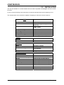
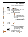
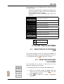
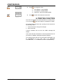
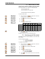
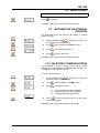
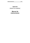
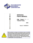
VD-310 SERIES
USER MANUAL
Scale Indicator
ABS/INOX
REF.: 49-MVD31EN01
VD-310
INDEX
1. INSTRUMENT DESCRIPTION..........................................................................................1
2. INTRODUCTION ...............................................................................................................1
2.1.
2.2.
2.3.
2.4.
DISPLAY’S FEATURES ........................................................................................................... 1
INSTALLATION......................................................................................................................... 2
KEYPAD.................................................................................................................................... 4
DISPLAY ................................................................................................................................... 5
3. OPERATION .....................................................................................................................6
3.1. SWITCHING ON THE DISPLAY............................................................................................... 6
3.2. NORMAL WEIGHING ............................................................................................................... 6
3.3. TARE......................................................................................................................................... 6
3.3.1. Setting the tare .................................................................................................................. 6
3.3.2. Selecting the programmed tare ......................................................................................... 7
3.4. RESET KEY .............................................................................................................................. 7
3.5. GROSS WEIGHT OR NET WEIGHT KEY ............................................................................... 7
3.6. COUNTING-PIECES MODE..................................................................................................... 7
3.6.1. Operative in sampling counting pieces mode.................................................................... 7
3.6.2. Operative in mode Counting-pieces PLU (CLU)................................................................ 8
3.6.3. Selecting unit counter CLU ................................................................................................ 9
4. CHECKWEIGHER MODE (OPTIONAL) .........................................................................10
5. OPTION TWO PLATFORMS ..........................................................................................11
5.1.
5.2.
SELECTION OF PLATFORM IN USE .................................................................................... 11
SELECTING WEIGHING PLATFORMS................................................................................. 11
6. PRINTING FUNCTION ....................................................................................................12
7. PROGRAMMING USER PARAMETERS........................................................................13
7.1. PROGRAMMING PLU ............................................................................................................ 14
7.1.1. PLU’s target weight.......................................................................................................... 14
7.1.2. Type of limit of PLU ......................................................................................................... 15
7.1.3. FUNCTIONING OF THE BUZZER .................................................................................. 17
7.1.4. TYPE OF BUZZER .......................................................................................................... 17
7.1.5. Programming next PLU ................................................................................................... 17
7.2. TARE PROGRAMMING ......................................................................................................... 18
7.3. DATE & TIME.......................................................................................................................... 18
7.3.1. Programming Time .......................................................................................................... 18
7.3.2. Programming Date........................................................................................................... 19
7.4. TYPES OF TARE.................................................................................................................... 19
7.5. SELECTING FILTERS............................................................................................................ 20
7.6. SELECTING SPECIAL FILTER (WIND) ................................................................................. 20
7.6.1. Operative margin of the Filter for Wind............................................................................ 21
7.7. NON-OIML APPLICATIONS................................................................................................... 21
7.7.1. Limit of manual zero ........................................................................................................ 21
7.7.2. Initial reset limit ................................................................................................................ 22
7.7.3. Zero tracking limit ............................................................................................................ 22
7.8. MENU COUNTI....................................................................................................................... 23
7.9. INFORMATION ON INTERNAL DIVISIONS .......................................................................... 23
7.10.
SELECTING COMMUNICATIONS ..................................................................................... 23
7.11.
PROGRAMMING COMMUNICATIONS PARAMETERS.................................................... 24
7.11.1. Communication speed ..................................................................................................... 24
7.11.2. Data bits........................................................................................................................... 24
7.11.3. Parity................................................................................................................................ 25
7.11.4. Stop bits ........................................................................................................................... 25
7.12.
PRINTING PARAMETERS ................................................................................................. 25
49-MVD31EN01
I
USER MANUAL
USER MANUAL
7.12.1. Printing format ................................................................................................................. 25
7.12.2. Number of feed lines........................................................................................................ 26
7.13.
RETURN TO NORMAL WORKING MODE ........................................................................ 27
49-MVD31EN01
II
USER MANUAL
VD-310
1. INSTRUMENT DESCRIPTION
SCREEN
KEYPAD
2. INTRODUCTION
The indicator can be set up with OIML from 1 up to 10,000 divisions or with OIML from 0 up to
100,000 divisions.
This manual outlines the configuration process and handling of the visual display for use with one or
two platforms.
2.1. DISPLAY’S FEATURES
All indicators feature:
•
•
•
•
•
•
•
•
•
Connection for two independent weighing platforms. (Depending on the model)
Connection for up to 12 load cells
Weight in kilos or pounds.
Tare: two different operations.
Unit counter function.
Checkweigher function, with a maximum of 99 different ways of programming per
platform. (Depending on the model)
RS-232Communications
Communication to printer or remote display.
Options (VD-310 INOX Series):
o Relay outputs/Optocoupled inputs.
o RS-485
o Wireless communications.
o 4-20mA / 0-10 V
49-MVD31EN01
1
USER MANUAL
USER MANUAL
2.2. INSTALLATION
The VD-310 indicator is a scale indicator that can also incorporate Checkweigher and unit counter
functions.
For the correct functioning of the instrument you need an external power source supplying 12 Vcc
The external power source should be capable of supplying a continuous current of 500 mA
DATA
Load cells
Platforms
Up to 12, 350 OHM
1 or 2, Configurable (Optional 2nd
platform)
NON OIML: 100,000
OIML: 10,000
Divisions
Cell power voltage
Zero range
Input range
Temperature range
Class, OIML
5Vdc
0 to +2.5mV
0 to 15mV
-10ºC to +40ºC
Class III (up to 10,000div)
POWER
Power source
12Vdc, 500mA
WEIGHING
Units
Additional working modes
kilograms, pounds
Unit counter
Checkweigher
Display
6-digit LED, 25.4mm
COMMUNICATIONS
49-MVD31EN01
RS-232
Standard
Printer or remote display
Standard
RS-485
Optional (VD-310 INOX Series)
4-20mA / 0-10 V
Optional (VD-310 INOX Series)
Inputs/Outputs
Optional (VD-310 INOX Series)
Wireless
Optional (VD-310 INOX Series)
Casing
ABS (Plastic) or INOX
2
USER MANUAL
VD-310
ASSEMBLING THE INDICATOR
Load cells
Set-up for one platform
The platforms must be connected to the indicador by means of a 7 pins connector
The connections are as follows:
Connector 1
Pin 1:IN+
Pin 2: SENSE+
Pin 3:OUT+
Pin 4: OUTPin 5: SENSEPin 6: INPin 7: NOT USED
Set-up for a double platform (Optional)
The loadcells must be connected to the indicador by jeans of a 7 pins connector.
The connections for the pins are as follows:
Platform C1:
Platform C2:
Pin 1: …..IN +
Pin 2: …..SENSE +
Pin 3: …..OUT +
Pin 4: …..OUT –
Pin 5: …..SENSE Pin 6: …..IN Pin 7: …..NOT USED
Pin 1: …..IN +
Pin 2: …..SENSE +
Pin 3: …..OUT +
Pin 4: …..OUT –
Pin 5: …..SENSE Pin 6: …..IN Pin 7: …..NOT USED
Power
External power must be connected to the connector of power.
Pin 1: Positive.
Pin 2: Negative
RS-232
There are two RS-232 channels, with the following pin-out:
49-MVD31EN01
Channel 1
Pin 7: …..Transmision
Pin 8: …..Reception
Pin 6: …..GND
Channel 2
Pin 3: …..Transmision
Pin 2: .....Reception
Pin 1: …..GND
3
USER MANUAL
USER MANUAL
2.3. KEYPAD
This keypad is composed of 7 keys on one single row.
ABS
INOX
Symbol
Description
twice for less that
TARE: Press
two seconds and the tare value is set.
SELECTING THE PROGRAMMED TARE
To remove the tare setting, remove the
.
weight and press
One tap
Prolonged tap (>1 seconds)
GROSS WEIGHT/NET
USER PROGRAMMING MENU
ZERO
TECHNICAL CONFIGURATION MENU
ENABLE/DISABLE CHECKWEIGH MODE
(Optional)
SEND DATA TO PC/PRINTER
SELECTING C1-C2 PLATFORM (Optional)
kg/lb.: If pressed, the display changes
weight unit for a certain length of time UNIT COUNTER MODE
(Kg or lb.)
ON/OFF
49-MVD31EN01
4
USER MANUAL
VD-310
2.4. DISPLAY
The display shows the weight and all the programming screens.
The series of symbols indicate:
Gross weight
Net weight, a tare has been selected.
Zero
Stability
Platform 1 Enabled
Platform 2 Enabled
Kg, lb.,
.
Weight unit or unit counter mode.
When the first LED lights up, you are working in checkweigher mode.
HighK
Below
State of the weight in checkweigher mode depending on the limits
Ok
49-MVD31EN01
Above
5
USER MANUAL
USER MANUAL
3. OPERATION
3.1. SWITCHING ON THE DISPLAY
Having ensured that the device has been properly installed,
connect the adaptor 230VAC-12VDC to the corresponding
connector. Then plug the power cable into the mains.
and hold for a few seconds, until the display lights
Press
up. The display will follow the steps outlined below if both
platforms are enabled:
··········
¾
Display test: “0, 1, 2, 3, 4,....”
¾
Metrological Software Version: “OIML 1.0”
¾
User Software Version: “u 3.31”
¾
If the external calibration of platform C2 is enabled:
“C2oPEn” allows for the configuration of external
parameters and the calibration process.
¾
If the external calibration of platform C1 is enabled:
“C1oPEn” allows for the configuration of external
parameters and the calibration process.
¾
The indicator is ready for use depending to the active.
To switch off, press
and hold for a few seconds.
3.2. NORMAL WEIGHING
Place the item to be weighed on the weighing platform. The
weight will display on the screen.
3.3. TARE
To tare an object:
1. Place the item to be tared on the platform.
.
2. Press
The VD-310 indicator includes the possibility of programming
10 PLU´s for tare ( TLU´s) for each platform.
The tare cannot be gauged if the weight is not
stable.
3.3.1. Setting the tare
Place the weight to be tared on the weighing platform.
Press the
key twice
If the tare has not been set, on removing the weight, the tare
will automatically reset to zero. To remove the tare setting,
remove the weight and press
. Successive tare operations
can be carried out but always on a greater weight (see
section: 7.4 TYPES OF TARE).
49-MVD31EN01
6
USER MANUAL
VD-310
3.3.2. Selecting the programmed tare
From weighing mode:
to access selecting the
1.
Press and hold the key
programmed tare submenu.
2.
Press
3.
Press
4.
The instrument switches to weighing mode while
indicating the tare selected
to select the required PLU.
This type of tare operates in the same way as a tare set
manually.
3.4. RESET KEY
The indicator has a manual device for clearance to zero; if, for
some reason or other, on removing the weight from the
weighing platform, the value of the weight is not zero and is
within a given margin, the scale can be reset by pressing the
key.
3.5. GROSS WEIGHT OR NET
WEIGHT KEY
If you press the
key, the weight display changes
temporarily, changing from net weight to gross weight, the
latter displaying for a few seconds.
3.6. COUNTING-PIECES MODE
The VD-310 indicator incluyes the possibility of programming
200 countin-pieces PLU´s (CLU´s). These CLU´s are
common for bothe platforms.
The VD-310 working in counting pieces mode can be used in
two different ways: sampling mode and counting pieces
PLU´s (CLU´s).
3.6.1. Operative in sampling counting
pieces mode.
From the normal working mode, keeping the key
pressed
longer than 1 second, the indicator starts working in counting
pieces mode.
is
When the equipment is working in this mode, the LED
on without flashing. (if the led is flashing the indicator is in
mode Counting pieces PLU ( CLU).
The indicator shows flashing in the display the last number of
pieces requested for sampling ( the default value is 10 units).
It is possible to modify the number of pieces to be placed on
the platform by pressing the key
.
The possible values are: 10, 20, 30, 50 y 100.
49-MVD31EN01
7
USER MANUAL
USER MANUAL
Place on the platform the number of pieces selected and
press the key
.
When the calculation of the single weight of each piece has
been calculated, the indicator shows the number of pieces
placed on the platform, from this moment the equipment
shows the number of pieces placed on the platform.
.
To return to the normal working mode press
If the message “Add” appears on the display, the weight of
the number of pieces is under the minimum weight necessary
to perform a sample, it is necessary to perform a sample with
more pieces, to do it the procedure is the following:
1. Select abigger number of pieces by pressing the key
2.
3.
.
Place on the platform the exact number of pieces
selected.
, if the message “Add” remains on the
Press
display, repeat the three steps by selecting a higher
number of pieces.
If the indicator shows the message “Lo-P”, the minimum
weight readable by the platform is bigger than the unitary
weight of the pieces to be weighed.
In this case, it is recommended to work with a platform with a
lower range.
If the weight is instable, alter few seconds the display Hill
show “noStbL” and the number of pieces selected will flash.
The calculation of unitary weight has not been done.
Press
when the weight is stable.
3.6.2. Operative in mode Counting-pieces
PLU (CLU)
From the normal working mode, keeping the key
pressed
longer than 1 second, the indicator starts working in counting
pieces mode.
is
When the equipment is working in this mode, the LED
flashing. (if the led is on and not flashing the indicator is in
mode Sampling Counting pieces.
A CLU Hill always be selectec until make the selection of a
new one or until deactivate the counting pieces funtion.
To return to normal working mode press
.
To make a new calculation of the number of pieces, press
to select the new value of the number of pieces to be placed
on the platform, the unitary weight of the piece is set to zero
stops flashing. The rest of the process is the
and the led
same as the mode of sampling counting pieces mode ( see
3.6.1 Operative in mode sampling counting pieces).
49-MVD31EN01
8
USER MANUAL
VD-310
3.6.2.1.
Programming of CLU´s
To program a CLU it is necessary to have calculated
previously the unitary weight of the piece according to the
paragraph 3.6.1 Operative in sampling counting pieces
mode.
1. When the indicator shows the number of units, press the
longer than 1 second to access the CLU
key
programming Menu.
to access selection of number of CLU to be
2. Press
programmed.
to change the selected CLU
3. Press
4. The selected digit blinks.
and
5. Use
to select the digit to be changed.
6. The digit is changed by pressing
.
to set the value. You will be informed of the
7. Press
platform in which the CLU has been programmed.
to return to counting pieces mode. If the user
8. Press
wants to program more CLU´s the procedure is:
to select the number of pieces to be
a. Press
placed in the platform as sample.
b. Place on the platform exactly the number of pieces
selected and press
.
c. Continue in paragraph 1 of 3.6.2.1.
9. To return to the normal working mode, press the key
.
3.6.3. Selecting unit counter CLU
To select one of the CLU’s the unit counter CLU function must
be enabled and a CLU must have been programmed.
1. With the indicator working in counting pieces mode, press
for more than one second.
the key
to choose between:
2. Use
0.
1.
Unit counter CLU function Disabled.
Unit counter CLU function Enabled.
.
3. Press
a. If unit counter CLU function disabled has been
selected, the indicator quits to unit counter mode
and maintains the last unit counter calculation.
b. If unit counter CLU function enabled has been
selected, the indicator moves on to select the
programmed CLU required (pt. 4).
to change the selected CLU
4. Press
5. The selected digit blinks
and
6. Use
to select the digit to be changed
7. The digit is changed by pressing
49-MVD31EN01
9
.
USER MANUAL
USER MANUAL
to set the value. You will be informed of the
8. Press
platform in which the CLU has been programmed.
9. Press
.
10. If you wish to select another CLU, press
to quit to unit counter mode press
or
. If you wish
.
11. To return to the normal working mode, press the key
.
4. CHECKWEIGHER MODE
(Optional)
The VD-310 indicator has as an option a Checkweigher
function.
To select the checkweigher function:
1.
Keep the key
2.
Press
function.
0.
1.
3.
pressed for longer than 1 second.
to enable or disable the Checkweigher
Checkweigher function disabled.
Checkweigher function enabled.
If the function is enabled, it is necessary to select a
checkweigher PLU (see 7.1 PLU Programming). The
procedure is the following:
1. Press
to select the selecting PLU submenu
to change the PLU.
2. Press
3. The selected digit blinks.
4. Use
and
changed.
to select the digit to be
5. The digit is changed by pressing
6. Press
to set the value. The value of the
upper limit of the PLU displays.
. The value of the lower limit of the
7. Press
PLU displays.
8. Press
.
9. To select another PLU, press
check weigher mode press
or
4.
, to return to
.
To return to normal working mode( exit chack weigher
mode), keep pressed the key
for longer than one
second . By pressing the key
select 0 (
checkweigher function disabled) and press the key
49-MVD31EN01
10
.
USER MANUAL
VD-310
The algorithm of the checkweigher leds is shown with the
following example:
Article with a target weight of 1000g with an upper limit of
5g and a coger limit of 10g ( so the minimum weight will
be 990g and the maximum 1005g).
The functioning of the checkweigher leds will be the
following:
Checkweigher mode enabled.
Weight between 970 and 980g
Weight between 980 and 990g.
Weight between 990 and 1000g.
Weight of 1000 g ( target weight)
Weight between 1000 and 1005g.
Weight between 1005 and 1010g
Weight between 1010 and 1015g
Weigth over 1015g
LED ON
LED OFF
5. OPTION TWO PLATFORMS
5.1. SELECTION OF PLATFORM IN
USE
The VD-310 indicator has as an option the possibility of
working with two platforms. To select the platform in use (1 or
2) , keep pressed the key
for longer than 1 second.
5.2. SELECTING WEIGHING
PLATFORMS
The instrument can be set up to work with one or two
platforms, depending on the model.
To select the platform to be used, take the following steps:
········
1.
count from 0 to 9, press and hold the
screen will display “c1-c2”.
2.
49-MVD31EN01
Switch on the device. When the display shows the
Press
submenu.
11
to
select
the
System
. Key. The
Configuration
USER MANUAL
USER MANUAL
3.
to change the value.
Press
1.
2.
3.
4.
Press
··········
Only platform 1 (C1) enabled.
Only platform 2 (C2) enabled.
Platforms 1 (C1) and 2 (C2) enabled.
to store and reboot the instrument.
6. PRINTING FUNCTION
The VD-310 indicator can send information to a serial printer.
To do so; press
when the weight on the platform is stable.
Once the printing has been done, printing can be resumed in
the following cases:
1. There has been a change in the weight
2. After 5 seconds
If these conditions are not met, the “nEu” message will
display.
In the event that the transmission is at low speed and has not
yet finished, a “busY” message temporarily displays.
The printing format and the communication parameters can
be programmed by the user (see 7.12 PRINTING
PARAMETERS, 7.11 COMMUNICATIONS PARAMETERS).
49-MVD31EN01
12
USER MANUAL
VD-310
7. PROGRAMMING USER
PARAMETERS
These parameters allow the user to adapt the instrument’s
operation to installation requirements.
The user menu contains the following functions:
•
Programming of Checkweigher PLU´s (depending
on the version).
•
Tares programming.
•
Programming Time and Date.
•
Selecting types of tare.
•
Weighing filters selection.
•
Enabling the filter for conditions of instability.
•
Changing Non OIML parameters.
•
Internal divisions reading.
•
Communications setup.
•
Selection of communication parameters.
•
Selecting printing formats.
•
Exit from menú, return to normal working mode.
To gain access to the parameters of User´s Programming,
from the normal working mode, press the key
than 1 second.
By pressing several times the key
programmation submenus.
for longer
the indicator shows the
The configuration and programming
independent for each of the platforms.
parameters
are
The procedure for programming configuration parameters for
platforms C1 and C2 is the same.
49-MVD31EN01
13
USER MANUAL
USER MANUAL
7.1. PROGRAMMING PLU
In this submenu it is programmed the Checkweigher PLU.
The indicator has the possibility of programming 99 PLU´s for
each platform
To enable the checkweigher
CHECKWEIGHER MODE
mode
see
section
4-
1.
From normal working mode, keep pressed the key
for longer than 1 second.
2.
Press
3.
Enter the number of PLU to be programmed (from 1 to
99), to do so:
to select the PLU programming submenu.
in order to be able to change the
1. Press
value.
2. The selected digit blinks.
3. Use
and
changed.
to select the digit to be
4. The digit is changed by pressing
.
5. Press
to set the value and pass to program
the target weight of the PLU.
7.1.1. PLU’s target weight
This parameter is for programming the PLU’s target weight, to
do so:
1. Press
in order to be able to change the
value.
2. The selected digit blinks.
3. Use
and
changed.
to select the digit to be
4. The digit is changed by pressing
.
5. Press
to set the value and pass to program
the type of limit of the PLU.
49-MVD31EN01
14
USER MANUAL
VD-310
7.1.2. Type of limit of PLU
This parameter is for selecting one of the two types of limit.
The possible limits are:
1.
The upper and lower values are selected as a
percentage of the target weight.
2.
The upper and lower values are selected as
weight intervals.
to select the type of limit of PLU.
1.
Press
2.
to set the value and pass to program the
Press
upper limit.
Example:
The indicator is programmed with a step of 5g and we
want a target weight of 1000g. Both the upper and lower
limit are 10g. It is possible to select both types of limit
(percentage or steps).
In type of limit percentage it is necessary to program 1%
as lower and upper limit
In type of limit steps it is necessary to program 2 steps as
lower and upper limit.
The indicator is programmed with a step of 5g and we
want a target weight of 1000g. The upper limit is 10g and
lower limit is 5g. It is possible only to select type of limit
steps because it is not possible to program decimals in
the percentage of limit.
In this case, it is only possible to program to program 2
steps as upper limit and one step as lower limit.
7.1.2.1. TYPE OF LIMIT BY PERCENTAGE
It is not possible to program decimals in this parameter
Upper limit
This parameter is for programming the upper limit in % of the
target weight. Take the following steps:
in order to be able to change the
1. Press
value.
2. The selected digit blinks.
and
3. Use
changed.
to select the digit to be
4. The digit is changed by pressing
.
5. Press
to set the value and pass to program
the lower limit.
49-MVD31EN01
15
USER MANUAL
USER MANUAL
Lower limit
This parameter is for programming the lower limit in % of the
target weight. Take the following steps:
1. Press
in order to be able to change the
value.
2. The selected digit blinks.
3. Use
and
changed.
to select the digit to be
4. The digit is changed by pressing
.
to set the value and pass to program
5. Press
the functioning of the buzzer.
7.1.2.2. TYPE OF LIMIT BY WEIGHT STEPS
Upper limit
This parameter is for programming the Upper limit in weight
intervals. Take the following steps:
1. Press
in order to be able to change the
value.
2. The selected digit blinks.
3. Use
and
changed.
to select the digit to be
4. The digit is changed by pressing
.
5. Press
to set the value and pass to program
the lower limit..
Lower limit
This parameter is for programming the Lower limit in the
display’s weight intervals. Take the following steps:
1. Press
in order to be able to change the
value.
2. The selected digit blinks.
3. Use
and
changed.
to select the digit to be
4. The digit is changed by pressing
.
to set the value and pass to program
5. Press
the functioning of the buzzer..
49-MVD31EN01
16
USER MANUAL
VD-310
7.1.3. FUNCTIONING OF THE BUZZER
There are two modes of working of the buzzer:
1.
A sound is emitted when the weight is within the
limits
2.
A sound is emitted when the weight is outside the
limits and is greater than 20 divisions of the lowest
range used.
to select the type of sound required.
1.
Press
2.
to set the value and pass to program the
Press
type of buzzer.
7.1.4. TYPE OF BUZZER
There are three types of buzzer sound:
1.
No sound.
2.
Several beeps once.
3.
Several beeps several times.
1.
Press
to select the required Sound mode.
2.
Press
to set the value.
7.1.5. Programming next PLU
Once a PLU has been programmed:
•
Press
to program another PLU
•
Press
mode
to return to the User´s Programming
See Par 7.13 to return to the normal working mode.
49-MVD31EN01
17
USER MANUAL
USER MANUAL
7.2. TARE PROGRAMMING
The VD-310 indicator includes the tare programming function.
The VD-310 has the possibility of programming 10 preset
tares (TLU) for each platform.
The operation for the programming of the tares is as follows:
1.
In normal working mode, place the tare weight on the
platform and press
.
2.
for longer than 1 second to
Keep pressed the key
access the User´s Programming.
3.
Press
4.
you access the “tLU
If there is tare, if you press
01” submenu. Otherwise a series of beeps will indicate
that there is no tare to be programmed.
5.
to select the number de TLU where you wish
Press
to program the tare.
6.
to store the tare and return to normal
Press
working mode.
until you reach the screen “tLUPro”.
7.3. DATE & TIME
Use this submenu for programming the time and the date of
the instrument.
Date and time are not kept when the indicator is switched
off.
7.3.1. Programming Time
1.
for longer than 1 second to
Keep pressed the key
access the User´s Programming.
2.
Press
to select the programming time submenu.
3.
Press
.
4.
Press
.
5.
Enter the time in the “HH.MM.SS” format, to do so:
in order to be able to change the
1. Press
value.
2. The selected digit blinks.
3. Use
and
changed.
to select the digit to be
4. The digit is changed by pressing
.
to set the value and move on to the
5. Press
next parameter.
49-MVD31EN01
18
USER MANUAL
VD-310
7.3.2. Programming Date
.
1.
Press
2.
Enter the date in “DD.MM.YY” the format. To do so:
in order to be able to change the
1. Press
value.
2. The selected digit blinks.
3. Use
and
changed.
to select the digit to be
4. The digit is changed by pressing
.
5. Press
to set the value and return to the
user´s programming mode
See Par 7.13 to return to the normal working mode.
7.4. TYPES OF TARE
The Tare is always subtracted, i.e., the weight of the item
being tared is discounted from the maximum range of the load
cell, thus reducing its range.
To select types of tares:
1.
for longer than 1 second to
Keep pressed the key
access the User´s Programming.
2.
Press
until you reach the “tArE” screen
3.
Press
.
4.
Press
to change the value.
1.
Successive tares are not allowed.
2.
Successive tare operations are allowed, but
only on a greater weight.
to set the value and return to the user´s
Press
programming mode.
See Par 7.13 to return to the normal working mode.
49-MVD31EN01
19
USER MANUAL
USER MANUAL
7.5. SELECTING FILTERS
These filters allow to adapt the weighing characteristics of the
indicator the site where it is installed ( open area, platform
with strong vibrations, etc). There are 7 selectable filters.
Filtro 0 Î Deafult value.
Filtro 1 Î Platform in an open area.
:
:
Filtro 6 Î Platform with strong vibrations.
To select the filter value:
1.
Keep pressed the key
for longer than 1 second to
access the User´s Programming
2.
Press
until you reach the “FILtEr” screen
3.
Press
.
4.
Press
to change the value.
ICS1 rdS1 rdM1 ICS2 rdS2 rdM2
3
4
5
4
4
5
Grade 1
Grade 2
Grade 3
Grade 4
Grade 5
Grade 6
5.
1
2
2
1
1
2
1
2
3
1
1
2
5
6
6
5
5
6
1
2
2
3
1
2
1
2
3
2
1
2
Average
reading
1
1
1
2
3
3
to set the value and return to the user´s
Press
programming mode.
See Par 7.13 to return to the normal working mode.
7.6. Selecting special filter (wind)
This filter is used when plant conditions or the wind could
affect stability.
Use this submenu to choose:
0.
1.
Special filter Disabled.
Special filter Enabled.
To program this parameter:
1.
for longer than 1 second to
Keep pressed the key
access the User´s Programming.
2.
Press
until you reach the “und” screen
3.
Press
.
4.
Press
to change the value.
0.
1.
5.
49-MVD31EN01
Special filter Disabled.
Special filter Enabled.
to set the value and move on to the next
Press
parameter.
20
USER MANUAL
VD-310
7.6.1. Operative margin of the Filter for Wind
This parameter defines the margin of steps in which the wind
filter will be applied.
To program this parameter:
in order to be able to change the
1. Press
value.
2. The selected digit blinks.
3. Use
and
changed.
to select the digit to be
4. The digit is changed by pressing
.
5. Press
to set the value and return to the
user´s programming mode.
The default value of the filter’s operating margin is 5e
See Par 7.13 to return to the normal working mode.
7.7. NON-OIML APPLICATIONS
If the instrument is not used under OIML requirements, it is
possible to adjust the initial parameters.
If the instrument is used under OIML requisites, sections
7.7.1, 7.7.2, and 7.7.3 are not programmed.
7.7.1. Limit of manual zero
This parameter indicates the % of the maximum with which
manual zero can be done.
To program this parameter:
1.
for longer than 1 second to
Keep pressed the key
access the User´s Programming.
2.
Press
3.
Press
4.
Enter the % of the maximum range (from 0 to 99 %)
with which you wish to allow reset. To do so:
until you reach the “rSorot” screen
.
in order to be able to change the
1. Press
value.
2. The selected digit blinks.
3. Use
and
changed.
to select the digit to be
4. The digit is changed by pressing
.
5. Press
to set the value and move on to the
next parameter.
49-MVD31EN01
21
USER MANUAL
USER MANUAL
7.7.2. Initial reset limit
This parameter indicates the % of the maximum range with
which initial reset is allowed.
To program this parameter:
Enter the % maximum range (from 0 to 99 %) with which you
wish to allow initial reset. To do so:
1. Press
in order to be able to change the
value.
2. The selected digit blinks.
3. Use
and
changed.
to select the digit to be
4. The digit is changed by pressing
.
to set the value and move on to the
5. Press
next parameter.
7.7.3. Zero tracking limit
This parameter indicates the % of the interval with which you
wish to go from zero to the first interval.
To program this parameter:
Enter the % of the interval (from 0 to 99 %) with which you
wish to allow the jump from zero to the first interval. To do so:
1. Press
in order to be able to change the
value.
2. The selected digit blinks.
3. Use
and
changed.
to select the digit to be
4. The digit is changed by pressing
5. Press
.
to set the value.
See Par 7.13 to return to the normal working mode.
49-MVD31EN01
22
USER MANUAL
VD-310
7.8. MENU COUNTI
Submenu not in use.
Press
to continue.
See Par 7.13 to return to the normal working mode.
7.9. INFORMATION ON INTERNAL
DIVISIONS
This parameter shows the value of the weight in internal
divisions. To do it:
1.
for longer than 1 second to
Keep pressed the key
access the User´s Programming.
2.
Press
until you reach the “ICount” screen
3.
Press
to view internal divisions.
4.
Press
to quit to user menu.
See Par 7.13 to return to the normal working mode.
7.10. SELECTING COMMUNICATIONS
This parameter is used for setting up the VD-310 Series
indicator for communicating with a serial printer, with the r TP05 repeater or with the RD-3 repeater.
To select communications:
1.
for longer than 1 second to
Keep pressed the key
access the User´s Programming.
2.
Press
until you reach the “CoMM” screen
3.
Press
to change the value.
1.
2.
3.
4.
Communication with RD-3 repeater.
Communication with TP-05 repeater
Communication with serial printer.
to set the value and return to the user´s
Press
programming mode
See Par 7.13 to return to the normal working mode.
49-MVD31EN01
23
USER MANUAL
USER MANUAL
7.11. PROGRAMMING
COMMUNICATIONS PARAMETERS
Use this submenu for programming the communication
speed, the data bits, the parity and the stop bits with which
the instrument is to communicate
7.11.1.
Communication speed
This parameter is for selecting the speed in bauds at which
the indicator is to communicate.
To program the communication speed:
1.
for longer than 1 second to
Keep pressed the key
access the User´s Programming.
2.
Press
until you reach the “uArt” screen
3.
Press
.
4.
To change the communication speed press
.
001 = 1200 bps
002 = 2400 bps
004 = 4800 bps
009 = 9600 bps
019 = 19200 bps
038 = 38400 bps
057 = 57600 bps
115 = 115200 bps
5.
to set the value and move on to the next
Press
parameter.
7.11.2.
Data bits
This parameter is for selecting the data bits with which the
indicator is to communicate.
To do so:
1.
Press
bits.
if you wish to change the number of data
7 7 data bits.
8 8 data bits.
2.
49-MVD31EN01
to set the value and move on to the next
Press
parameter.
24
USER MANUAL
VD-310
7.11.3.
Parity
This parameter is for selecting the communications parity.
To do so:
1.
Press
if you wish to change the parity.
0 No parity.
1 Odd parity
2 Even parity.
2.
to set the value and move on to the next
Press
parameter.
7.11.4.
Stop bits
This parameter is for selecting the number of stop bits.
To do so:
1.
if you wish to change the number of stop
Press
bits.
1 One stop bit.
2 Two stop bits.
2.
to set the value and return to the user´s
Press
programming mode.
See Par 7.13 to return to the normal working mode.
7.12. PRINTING PARAMETERS
Use this submenu to select the printing formats and the feed
lines on the paper after printing.
7.12.1.
Printing format
To select the printing format:
1.
for longer than 1 second to
Keep pressed the key
access the User´s Programming.
2.
Press
until you reach the “PrnFrm” screen
3.
Press
.
4.
To change the printing format press
.
Select one of the following formats:
49-MVD31EN01
25
USER MANUAL
USER MANUAL
Printing formats for weighing
1
Weighing Number:
#XXXXX
hh:mm
mm/dd/yy
Net:
XX.XXX Kg
Tare:
XX.XXX Kg
-------------------------------------------
2
Weighing Number:
#XXXXX
hh:mm
mm/dd/yy
Net:
XX.XXX Kg
Tare:
XX.XXX Kg
Goss:
XX.XXX Kg
-------------------------------------------
Printing formats for unit counter
3
Weighing Number:
#XXXXX
hh:mm
mm/dd/yy
Unit W:
0.000000 g
Tare:
XX.XXX Kg
Goss:
XX.XXX Kg
Net:
XX.XXX Kg
Quantity:
XXXXXX u
-------------------------------------------
4
Weighing Number:
#XXXXX
Unit W:
0.000000 g
Goss:
XX.XXX Kg
Net:
XX.XXX Kg
Quantity:
XXXXXX u
-------------------------------------------
Printing formats for checkweigher
5.
5
Weighing Number:
#XXXXX
hh:mm
mm/dd/yy
Target weight:
XX.XXX Kg
Actual weight:
XX.XXX Kg
Deviation:
XX.XXX Kg
-------------------------------------------
6
Weighing Number:
#XXXXX
Target weight:
XX.XXX Kg
Actual weight:
XX.XXX Kg
Deviation:
XX.XXX Kg
-------------------------------------------
to set the value and move on to the next
Press
parameter.
7.12.2.
Number of feed lines
Enter the number of lines (0-99), to do so:
in order to be able to change the
1. Press
value.
2. The selected digit blinks.
3. Use
and
changed.
to select the digit to be
4. The digit is changed by pressing
.
to set the value and return to the
5. Press
user´s programming mode.
See Par 7.13 to return to the normal working mode.
49-MVD31EN01
26
USER MANUAL
VD-310
7.13. RETURN TO NORMAL WORKING
MODE
Once in User Programming Parameters, if the user wants to
the return to the normal working mode, press
reach the “Quit” screen. Then press
mode.
49-MVD31EN01
27
until you
to quit to weighing
USER MANUAL
DECLARATION OF CONFORMITY
No. of the notified body in charge of EU Verification conformable to Directive 90/384/EEC:
0317
DIBAL, S.A.
Astintze 20-24
Pol. Ind. Neinver
48160 – Derio SPAIN
Manufacturer:
No. of EC type-approval certificate:
Type:
VD-310 SERIES
TC6490
It corresponds to the model described in the CE type-approval certificate, as per requisites of Directive
90/384/CEE modified in accordance with what is laid down in the following EC directives: 89/336/CEE,
73/23/CEE, tests and checking in accordance with European standard EN45501 section 8.2.
In the event of confirmation being carried out in two stages, the validity of the declaration of conformity may
depend on the documentation on the realisation of the second stage of verification.
True copy of the manual entrusted to notified body no. No. 317
The information contained in this manual may be modified by the manufacturer without prior
notice
Ref.: 49-MVD31EN01 Rev.: 01
13/09/04