1
User’s Manual
1
User’s Manual
Preface
Thank you for choosing a Samsung Network Video Recorder (Disk Player) product.
This instruction manual provides detailed information and instructions for the SNR-6400 and
SNR-3200 network DVR products. Please read this manual and any supplementary
document(s) thoroughly before attempting to install and/or operate the product.
The contents of this manual, and the software and hardware explained herein, are protected by
copyright law. All copy, reprint and translation to other languages of a part of or all of the
contents of this instruction manual without permission of Samsung Techwin Co., Ltd. are
expressly prohibited except for fair use within the scope of copyright law.
The specifications of the product may change without prior notice for product improvement.
Product Warranty and Limited Liability
The manufacturer of this product is not responsible for the sale of the product, nor does the
manufacturer delegate such responsibility to a third party. The product warranty does not
extend to any accident, neglect, alteration, or misuse of the product. Furthermore, this
warranty does not cover any components or parts that are not supplied by the manufacturer of
this product.
The product warranty period is for three years from the purchase date. However, the warranty
does not cover any of the following problems, and a nominal service fee will be charged if:
z Product has been improperly used or handled by user.
z Product has been disassembled and/or altered by user.
z Product has been damaged by connecting a power supply with improper specifications.
z Product has been damaged due to an "Act of God" (fire, flood, tsunami, natural disaster,
etc.)
z To replace expendable components: HDD, Fan, etc.
(The warranty for the HDD and Fan is valid for one year from the purchase date.)
This warranty covers only the product supplied with the warranty.
After the warranty period (three years) has expired, a service fee will be charged for any
inspection and/or repair for the product. During the warranty period, a service fee will be
charged for repair and/or inspection for the product for any problems that are not covered by
the warranty.
1
Network Video Recorder SNR-6400/3200
This product is not an anti-theft or fire-prevention device; the manufacturer is not
responsible for any damage to property or personnel that may occur during its use.
This product must be installed by skilled and experienced personnel; self-installation by the
user is prohibited. Self-installation by the user may result in fire, electrocution, and/or product
malfunctions. Please contact your local dealer for assistance with the installation of the product.
This instruction manual is based on the product installed with the firmware version at 1.0.0.
The contents of this manual may change in order to accommodate upgrades in firmware
and/or software. Also, the specifications and/or design of this product may change without prior
notice for product improvement.
2
User’s Manual
Table of Contents
Preface............................................................................................. 1
Product Warranty and Limited Liability .......................................................................... 1
Table of Contents............................................................................ 3
Chapter 1. Overview ....................................................................... 7
1.1. Safety Precautions ......................................................................................... 7
1.2. Product Contents.......................................................................................... 10
Chapter 2. Part Names ................................................................. 11
2.1. Front Panel .................................................................................................... 11
2.2. Back Panel..................................................................................................... 13
2.3. Default Settings ............................................................................................ 14
2.3.1. Monitoring Page................................................................................................. 14
2.3.2. Playback Page ................................................................................................... 14
2.3.3. Config Page ....................................................................................................... 15
2.3.4. System Page...................................................................................................... 18
Chapter 3. Installation .................................................................. 19
3.1. Installing and Connecting Product ............................................................. 19
3.1.1. Supplying Power and Operating the Product .................................................... 19
3.1.2. Configuring the Network .................................................................................... 19
3.1.3. Internal HDD ...................................................................................................... 20
3.1.4. External HDD ..................................................................................................... 23
3.1.5. Sensor................................................................................................................ 24
3.1.6. Relays ................................................................................................................ 25
3.1.7. USB.................................................................................................................... 26
3.2. Connecting to the Website........................................................................... 26
3.2.1. Connecting Cable .............................................................................................. 26
3.2.2. Adding an IP Address......................................................................................... 26
3.2.3. Connecting and Changing Settings ................................................................... 28
Chapter 4. Operation .................................................................... 31
4.1. System Requirements .................................................................................. 31
3
Network Video Recorder SNR-6400/3200
4.2. Compatible Web Browsers .......................................................................... 31
4.3. Login .............................................................................................................. 32
4.4. Monitoring ..................................................................................................... 33
4.4.1. Splitting Screen and Changing Channels .......................................................... 33
4.4.2. Video Control ..................................................................................................... 34
4.4.3. PTZ Control........................................................................................................ 34
4.4.4. OSD Control....................................................................................................... 35
4.5. Playback ........................................................................................................ 36
4.5.1. Time Search....................................................................................................... 36
4.5.2. Event Search ..................................................................................................... 38
4.6. Config ............................................................................................................ 41
4.6.1. Status ................................................................................................................. 42
4.6.2. Record Setup ..................................................................................................... 43
4.6.3. Event Setup ....................................................................................................... 44
4.6.4. Camera Setup.................................................................................................... 47
4.6.5. HDD Setup......................................................................................................... 51
4.6.6. Network Setup ................................................................................................... 56
4.6.7. Time Setup......................................................................................................... 61
4.7. System ........................................................................................................... 63
4.7.1. Upgrade ............................................................................................................. 64
4.7.2. System Log ........................................................................................................ 66
4.7.3. User Setup ......................................................................................................... 69
4.7.4. Backup ............................................................................................................... 70
Chapter 5. LCD Setup................................................................... 75
5.1. System ........................................................................................................... 76
5.1.1. Checking Firmware Version ............................................................................... 76
5.1.2. Turning On/Off Beep .......................................................................................... 76
5.1.3. Relay Off ............................................................................................................ 77
5.1.4. System Update .................................................................................................. 77
5.1.5. Initializing Settings ............................................................................................. 78
5.1.6. HDD Check ........................................................................................................ 79
5.1.7. Shutting the System Down................................................................................. 80
5.2. Network Setup............................................................................................... 81
5.2.1. Monitor Ethernet Port Setup .............................................................................. 81
4
User’s Manual
5.2.2. Source Ethernet Port Setup ............................................................................... 84
5.2.3. Storage Ethernet Port Setup.............................................................................. 85
5.3. HDD Mode Setup........................................................................................... 86
5.4. Removing HDDs............................................................................................ 89
5.5. Formatting HDDs .......................................................................................... 90
5.5.1. Formatting a Single Internal HDD...................................................................... 90
5.5.2. Formatting All Internal HDDs ............................................................................. 91
5.5.3. Formatting a Single External HDD..................................................................... 91
5.5.4. Formatting All External HDDs ............................................................................ 92
5.5.5. Formatting All HDDs .......................................................................................... 93
Troubleshooting................................................................................................... 94
Product Specifications........................................................................................ 96
Product Dimensions............................................................................................ 98
5
User’s Manual
Chapter 1. Overview
This digital video recorder plus disk player features HDD storage and playback capabilities for
64/32-channel digital video.
Setting up this recorder is easy; you may use the buttons on the front of the product, or connect
to the product remotely via a network.
With proven performance and reliability, the SNR-6400/3200 is a self-sufficient video recorder
as well as ideal for digital video feed storage for monitoring systems of banks, apartment
buildings, and public offices that require a high security level. Since video is stored on hard disk,
there is no loss in picture quality due to repeated playback from the storage media. Further,
since all video data is stored as digital files, it is easily and quickly searchable.
This high-resolution video recorder features a large storage capacity and also comes with a
wide variety of user-friendly features such as: Simultaneous recording and playback
capabilities, motion detection, PTZ (pan, tilt, zoom) control, password, real-time voice data
recording, convenient access permissions setup using Key Lock, and maintenance of up to
10,000 event lists and log files.
1.1. Safety Precautions
The following information or instruction is vital for user safety; please
read it thoroughly to avoid serious injury or death.
Warning
Installing the Product
3 Please check the power outlet voltage (AC 100V~240V) before you connect the power
to the outlet.
3 Make sure that the product is switched off before you install it.
3 To avoid the risk of electric shock and/or fire, do not install the product in a damp area.
3 The product must be grounded to reduce the risk of electric shock.
Using the Product
3 Opening or removing the product case will expose you to the risk of electric shock; do
not open or remove the case unless you are a qualified technician.
7
Network Video Recorder SNR-6400/3200
3 To prevent electrical fire, do not connect multiple power cords to a single outlet.
3 Do not place heavy objects or vessels containing water on the unit since it can cause
serious malfunctions.
3 Do not use this item in a location containing propane gas, gasoline, or other flammable
substances to avoid risk of explosion or fire.
3 To avoid the risk of electric shock, do not touch the power plug with moisture on your
hands.
3 Make sure that no electrically conductive material enters the cooling vent.
3 Do not pull on the power plug with any force; a damaged plug may cause electric shock
or fire.
Disassembling and Cleaning the Product
3 There is a risk of malfunction, shock, or other dangers. Do not disassemble or attempt to
fix or alter the product yourself.
3 Do not clean the product with water, paint thinner, or other organic solvent as doing so
may cause product malfunctions and/or electric shock. When cleaning the product, use
a dry cloth to wipe the exterior of the device.
Misuse or wrongful operation of the item may result in injury or damage
to the item. It indicates caution should be observed when operating.
Caution
Installing the Product
3 When installing the product, please leave at least 15 cm of space between the cooling
vent and the wall for proper heat dissipation.
3 To prevent user injury and product damage, please install the product on a level surface
with no risk of the product falling.
3 Avoid installation in an environment where the product will be exposed to heat or direct
sunlight; product deformation and/or damage may result.
8
User’s Manual
Using the Product
3 Avoid shock and vibration while operating or moving the item.
3 Do not move the product while it is in operation; do not expose the product to strong
impact or throw the product.
3 If you wish to add a hard disk to the product, please contact your vendor; adding a nonrecommended hard disk may cause the product to function abnormally.
3 Arbitrarily adding a hard disk to the product will void your product warranty.
3 This product is not an anti-theft or fire-prevention device; the manufacturer is not
responsible for any damage to property or personnel that may occur.
Samsung Techwin recommends the installation of a UPS (Uninterrupted
Power Supply) with all its recording products.
Caution
Samsung
Techwin
cares
for
the
environment
at
all
product
manufacturing stages to preserve the environment, and is taking a
number of steps to provide customers with more environmentally
friendly products.
The
Eco
mark
represents
Samsung
Techwin's
will
to
create
environmentally friendly products, and indicates that the product
satisfies the EU RoHS Directive.
9
Network Video Recorder SNR-6400/3200
1.2. Product Contents
The contents of this product are as shown below.
Power Cord
Key
Rack Mount and Fixture
Screws
HDD Fixture Screws
User's Manual
Quick Reference Guide
Cross Cable
HDD Tray (4EA)
10
User’s Manual
Chapter 2. Part Names
2.1. Front Panel
No.
Name
Function
1
Key Lock
Turning the key completely engages the lock, so the buttons on the
front panel cannot be accessed and the HDD bay door cannot be
opened.
2
SATA-Bracket
Mounts hard disks for storing recorded video. Up to four hard disks
can be mounted. Mounted HDDs are referred to as Internal HDD1
(upper left), Internal HDD2 (upper right), Internal HDD3 (lower left),
and Internal HDD4 (lower right.)
3
Internal HDD1
A blue indicator means that Internal HDD1 is installed and
functioning normally. A red indicator means that Internal HDD1 is not
functioning properly.
4
Internal HDD2
A blue indicator means that Internal HDD2 is installed and
functioning normally. A red indicator means that Internal HDD2 is not
functioning properly.
5
Internal HDD3
A blue indicator means that Internal HDD3 is installed and
functioning normally. A red indicator means that Internal HDD3 is not
functioning properly.
6
Internal HDD4
A blue indicator means that Internal HDD4 is installed and
functioning normally. A red indicator means that Internal HDD4 is not
functioning properly.
7
EXTERNAL
HDD1
A blue indicator means that an external HDD is connected to the
rear eSATA Port1 and functioning normally. A red indicator means
that External HDD1 is not functioning properly.
8
EXTERNAL
HDD2
A blue indicator means that an external HDD is connected to the
rear eSATA Port2 and functioning normally. A red indicator means
that External HDD2 is not functioning properly.
9
EXTERNAL
HDD3
A blue indicator means that an external HDD is connected to the
rear eSATA Port3 and functioning normally. A red indicator means
that External HDD3 is not functioning properly.
11
Network Video Recorder SNR-6400/3200
No.
Name
Function
10
EXTERNAL
HDD4
A blue indicator means that an external HDD is connected to the
rear eSATA Port4 and functioning normally. A red indicator means
that External HDD4 is not functioning properly.
11
REC
A red indicator means that the product is in recording mode.
12
ALARM
A blue indicator means that an event in Input Group has occurred.
13
ERROR
A red indicator means that the product is not functioning properly.
14
RAID
A blue indicator means that the product is running in RAID mode.
15
LINK/ACT1
A blinking blue indicator means that a network cable is properly
connected to the Monitor Ethernet Port, and data communication is
taking place properly.
16
LINK/ACT2
A blinking blue indicator means that a network cable is properly
connected to the Source Ethernet Port, and data communication is
taking place properly.
17
LINK/ACT3
A blinking blue indicator means that a network cable is properly
connected to the Storage Ethernet Port, and data communication is
taking place properly.
18
POWER
A red indicator means that the product is powered on.
19
Config Ethernet
Port
Used to connect the product to a computer for the system
configuration.
20
LCD Panel
The panel displays the current status of the product; it can also be
used to change the system configuration with the adjacent buttons.
21
ESC Button
This button is used to change the system configuration. 'Chapter 5
LCD Setup' covers its use in detail.
22
Direction Button
Enter Button
This button is used to change the system configuration. 'Chapter 5
LCD Setup' covers its use in detail.
12
User’s Manual
2.2. Back Panel
No.
Name
Function
1
AC IN
Used to connect the product power cable.
2
SMPS FAN
This fan cools the power supply.
3
DC FAN
This fan cools the inside of the product.
4
Monitor Ethernet Port
A network port that allows the product to connect to a PC to
run Web Viewer.
5
USB Port
Used to upgrade the firmware version of the product.
6
Power Button
Turns on or off the product.
7
Source Ethernet Port
A network port that connects the product to the video camera.
8
SENSOR IN
/ RELAY OUT
Used to connect a sensor or alarm.
9
GROUND
A terminal that is used to ground the frame to an external
device.
10
Storage Ethernet Port
Used to connect NAS (Network Attached Storage) within the
same network.
11
eSATA Port1
Used to connect an external HDD.
12
eSATA Port2
Used to connect an external HDD.
13
eSATA Port3
Used to connect an external HDD.
14
eSATA Port4
Used to connect an external HDD.
15
RS232C Port
Unused terminal.
13
Network Video Recorder SNR-6400/3200
2.3. Default Settings
The following are the factory default settings for the product.
2.3.1. Monitoring Page
Main Menu
Sub Menu
Default Setting
Auto Sequence
Off
Display Mode
16Ch display
Group
1
Channel
1
Info
On
DIT
Off
PT, ZF
PT Activated
OSD
Off
PTZ speed
3
2.3.2. Playback Page
Main Menu
Time
Event
Sub Menu
Default Setting
Channel
-
Calendar
-
Time
-
Event Type
-
Channel
-
Date / Time
-
14
User’s Manual
2.3.3. Config Page
Record Setup
Main Menu
Sub Menu
Normal Record Config
Event Record Config
Record
Default Setting
All frames
Input Group
own event
Active
All frames
Inactive
I frames
Pre Recording Time
5 Sec
Post Recording Time
5 Sec
Button
Normal Record selected
Time Table
Always Normal Record
Event Setup
Main Menu
Local Sensor Type
Event Group
Sub Menu
Default Setting
Sensor1
Normal Open
Sensor2
Normal Open
Input Group
-
Output Group
-
Action Group
-
15
Network Video Recorder SNR-6400/3200
Camera Setup
Main Menu
Channel List
Channel Setup
Sub Menu
Default Setting
Open Channel List
Ch1 ~ Ch16
Select Channel
Ch01
Disable/Enable
Disable
Channel Name
Ch01, Ch02, Ch03, …
Model
-
Connection Type
Static IP
IP
0.0.0.0
Connection Port
4000
ID
-
Password
-
Picture Type
MPEG
ATC Mode
Off
Video Quality
High
Video Resolution
D1
Video Framerate
10
HDD Setup
Main Menu
HDD
Sub Menu
Repeat Recording
RAID Mode
NAS Configuration
Default Setting
Off
Normal
Nas Port
Nas1
Use
Disable
Name
-
Default Folder
-
IP
0.0.0.0
ID
-
Password
-
16
User’s Manual
Network Setup
Main Menu
Sub Menu
Default Setting
Monitor Ethernet Port
Connection Type
IP Address
Subnet Mask
Gateway
Connection Port
Http Port
ATC Mode
Static IP
0.0.0.0
0.0.0.0
0.0.0.0
4000
80
Disable
DDNS
Use
Server Domain
ID
Password
Disable
www.samsungipolis.com
-
Source Ethernet Port
Connection Type
IP Address
Subnet Mask
Gateway
Static IP
0.0.0.0
0.0.0.0
0.0.0.0
Source DHCP Server
Use
IP Range
Disable
0.0.0.0 ~ 0.0.0.0
Storage Ethernet Port
Connection Type
IP Address
Subnet Mask
Gateway
Static IP
0.0.0.0
0.0.0.0
0.0.0.0
DNS
DNS1
DNS2
168.126.63.1
168.126.63.2
RTP/RTSP
Use RTSP
RTSP Port
RTP Port
Use Multicast
Multicast Address
Disable
554
4000
Disable
224.0.1.1
E-Mail
SMTP Server Name
Use Authentification
ID
Password
E-Mail To
Yes
-
17
Network Video Recorder SNR-6400/3200
Time Setup
Main Menu
Time Configuration
NTP
Sub Menu
Default Setting
Date Format
mm.dd.yy
Time Format
24h
Time Zone
(GMT 00:00) Greenwich Mean Time
Use DST
Disable
Use Client
Disable
Use Server
Disable
Public Server1 Address
pool.ntp.org
Public Server2 Address
asia.pool.ntp.org
Public Server3 Address
europe.pool.ntp.org
Public Server4 Address
north-america.pool.ntp.org
Public Server5 Address
time.nist.gov
2.3.4. System Page
User
Main Menu
Admin
User
Sub Menu
Default Setting
Password
11111111
ID
user
Password
22222222
Authority
Only Monitoring is Allowed.
18
User’s Manual
Chapter 3. Installation
3.1. Installing and Connecting Product
3.1.1. Supplying Power and Operating the Product
Connect the power cord to the product as shown in the picture below.
Once the power cord is securely connected, press the power switch in the rear panel to boot
the system.
When the product is turned on, you can press the power switch briefly to turn off the product.
When the system has encountered an error and you can't turn it off normally, you can press
and hold down the power switch for five seconds to force the system to shut down.
Power Switch
3.1.2. Configuring the Network
The following picture is an example of a network diagram using the SNR-6400/3200. The 3
network ports on the product back panel are for a computer, camera, and NAS (Network
attached Storage.) Please Refer to "2.2. Back Panel" (Page 13)
The rear panel network ports can be used for devices within the same network, or in different
networks as shown in the example diagram.
19
Network Video Recorder SNR-6400/3200
.
3.1.3. Internal HDD
Open the HDD Bay as shown below to add, remove, or replace an internal HDD.
① Press PUSH
to open the Locking Door.
② Turn Key Lock counterclockwise to unlock.
20
User’s Manual
③ Open the HDD Door.
④ While pressing the HDD Hook down, pull on the handle to pull out the SATA Bracket.
⑤ Unscrew the fixture screws on the SATA Bracket before removing the HDD; fasten
the screws securely after you insert the HDD in the SATA Bracket.
21
Network Video Recorder SNR-6400/3200
⑥ Make sure that the SATA Bracket is pushed back all the way in the HDD Bay, and
close the HDD Door.
⑦ Turn Key Lock clockwise to lock.
⑧ Close the Locking Door.
22
User’s Manual
⑨ When adding a new, unformatted HDD, the product automatically formats the HDD.
Formatting HDD
is in Progress...
displaying the formatting process in the front LCD.
Internal HDD [2]
Added successfully!
Upon completing the formatting process, the message above is displayed in the LCD
along with a blue indicator in the HDD LED, indicating that the new HDD is ready to
use.
For a list of compatible HDDs, please refer to “※ Recommended HDDs”(Page
95)
Note
Do Not remove an HDD while the product is in operation. To safely remove
HDDs, please refer to "5.4. Removing HDDs"(Page 89)
Caution
To lock the HDD door, please make sure to turn Key Lock clockwise
completely.
Caution
3.1.4. External HDD
The SNR-6400/3200 supports an eSATA interface for connecting external storage devices; four
eSATA ports are located on the rear panel. The product can have up to 20 TB of storage
capacity by utilizing the internal HDDs and eSATA ports. (Based on 1TB data capacity per
HDD.)
An external eSATA HDD can be connected to the eSATA port on the rear panel as shown on
the next page. Note that an eSATA port does not supply power to the device connected to it;
the external device must supply its own power.
23
Network Video Recorder SNR-6400/3200
eSATA external HDD
You may connect an external HDD while the product is in operation. However,
this may result in certain models of external HDDs not being detected. As
such, it is recommended that you connect any external HDD by following the
steps outlined below.
Note
1. Turn the product off.
2. Connect the external HDD (also turned off) to the product with an eSATA
interface cable.
3. Turn on the external HDD.
4. Turn on the product.
The eSATA cable is not included with the product.
For a list of compatible HDDs, please refer to"※ Recommended HDDs"
(Page 95)
3.1.5. Sensor
The following are specifications and operating conditions for sensor input.
Number of Input Circuits
2
Input Types
N.C , N.O
Supported Sensor Types
Dry Contact sensors.
Connection Type
Attach stripped wire connections to the terminal block.
DC
150V
Output Current
Typical DC 12mA
Spec
Power
Please refer to the diagram on the next page to connect sensor inputs. It illustrates an example
of a dry contact sensor being connected to the product.
24
User’s Manual
For detailed instructions on connecting sensors, please refer to "4.6.3. Event Setup"(Page 44)
3.1.6. Relays
The following are specifications and operating conditions for alarm output.
Spec.
Number of Input Circuits
2 Relays
Output Types
Dry Contact.
Connection Type
Attach stripped wire connections to the terminal block.
DC
30V 1A
AC
125V 0.5A
Power
When connecting the relay outputs, first determine the attributes of the device to be connected
(Normal Open, or Normal Close), then connect the device by referring to the diagram below.
RELAY OUT 1
NC
CM
NO
Normal Close
O
O
-
Common
-
O
-
Normal Open
-
O
O
25
Network Video Recorder SNR-6400/3200
RELAY OUT 2
NC
CM
NO
Normal Close
O
O
-
Common
-
O
-
Normal Open
-
O
O
For detailed instructions on connecting the relay output, please refer to "4.6.3. Event Setup"
(Page 44)
3.1.7. USB
The USB ports on the rear panel are used to upgrade the product's firmware with the buttons
on the front panel. Please refer to “5.1.4. System Update “(Page 77)
3.2. Connecting to the Website
3.2.1. Connecting Cable
Press PUSH
on the front panel to open the Locking Door, then connect a PC to the Front
Panel Network Port with the supplied crossover cable as shown in the illustration below. (When
using a hub to connect the product to a computer, you may use a normal LAN cable instead of
a cross-over cable.)
3.2.2. Adding an IP Address
In your computer, click Start > Control Panel > Network Connections > Local Area Connection
> Properties.
26
User’s Manual
.
Select Internet Protocol (TCP/IP.) Click the Properties button then in the Internet Protocol
(TCP/IP) Settings dialog, click the Advanced button to open the Advanced TCP/IP Settings
dialog. (If the "Obtain an IP address automatically" option is checked under the Internet
Protocol (TCP/IP) Properties window, please click the "Use the following IP address" radio
button option before proceeding.)
Click Add under IP addresses then enter 192.168.1.xxx. The SNR-6400/3200 uses 192. 168. 1.
100 as the IP address; you cannot use the address for your computer's internal IP address.
27
Network Video Recorder SNR-6400/3200
3.2.3. Connecting and Changing Settings
Type 192.168.1.100 in your Internet browser address bar then press Enter.
In the login window, enter admin as the User ID and 11111111 for the Password. Click Login to
connect to the product.
28
User’s Manual
When connecting to the product for the first time, no video displays as no network or camera is
set up.
Clicking
at the top of the screen directs you to a new page, as shown in the
screenshot below.
Clicking
directs you to a new page, as shown in the screenshot below.
29
Network Video Recorder SNR-6400/3200
Use the left menu to set up the product. For detailed instructions on each menu item, please
refer to "4.6. Config"(Page 41) and "4.7. System"(Page 63) Once a network is set up,
You can use the Monitor Ethernet Port on the product back panel to connect to the product.
Note
The IP address for the front port is fixed as 192.168.1.100; this value cannot
be changed.
It is strongly recommended that you change the default administrator
password (Admin PW) as soon as possible. For instructions on changing the
password, please refer to "4.7.3. User Setup"(Page 69)
30
User’s Manual
Chapter 4. Operation
4.1. System Requirements
Category
Minimum
Recommended
CPU
Intel Pentium 4 / 3.0GHz
Core2duo E6750 or higher
Main Memory
1GB
2GB or higher
Video Memory
128MB
512MB or higher
Display Resolution
1024 x 768 (@ 32bit color) or higher
Hard Disk
1GB or higher
Operating System
Windows XP Professional / Windows Vista Business
Miscellaneous
DirectX 9.0 or higher
4.2. Compatible Web Browsers
Web Viewer is optimized for use with Microsoft Internet Explorer 6.0 or higher. You must have
Microsoft Internet Explorer 6.0 or higher installed on your PC to ensure trouble-free operation
of Web Viewer.
31
Network Video Recorder SNR-6400/3200
4.3. Login
Open a web browser, and then enter the IP address of the product. You are directed to the
login page. Enter your ID and password, then click the Login button to connect to the system.
You are directed to the Monitoring Page. If you have not set up your own ID and password yet,
the default ID is "admin", and the default password is "11111111" (without the quotation marks.)
For instructions on changing the ID and password, please refer to "4.7.3. User Setup"(Page
69)
Note
To connect to the product using the front network port, please make sure to
enter 192.168.1.100. To connect to the product using the rear Monitor Ethernet
Port, make sure to enter the IP address assigned to the port.
The connecting port and computer must be within the same network.
For an HTTP port number with any value other than 80, then the access
address is http://<IP address>:<HTTP port number>.
For example if the IP address is 192.168.1.110, and the HTTP port number is
8080, then the address for Web Viewer is http://192.168.1.110:8080.
For instructions on changing the Monitor Ethernet Port IP address, please
refer to “4.6.6. Network Setup”(Page 56)
32
User’s Manual
4.4. Monitoring
If you are logging in to your Network Video Recorder for the first time, or if you click the
button at the top of Web Viewer, you will be directed to the Monitoring Page
where you can view the video feeds from the cameras connected to your product.
4.4.1. Splitting Screen and Changing Channels
You can select the number of video feeds to simultaneously display on-screen by clicking the
button in the upper left of the screen. You can have 1-, 4-, 9-, 16-, 36-, or 64channel video feed(s) displayed simultaneously on-screen; a separate browser window will
open to display 36- or 64-channel video feeds. When displaying 1~36 channels, the channels
are displayed in groups to manage visibility.
For example, if you are viewing 16 channels simultaneously, then channels 1~16 are displayed
in group 1, and channels 17~32 are displayed in group 2, and so on.
is used to
select which group or channel you want to view; To watch video in all channels in an orderly
manner, click the
button. to activate the Auto Sequence option that cycles
through videos in different groups at 7-second intervals. The logs for the current channel are at
the bottom of the screen: event (MD, V-Loss), main frame sensor, and relay event. To check
the logs, move the
button on the right side of the window upward or downward. The names
of events like ‘MD’, ’V-Loss’ etc are displayed on the video of channels where events occur.
33
Network Video Recorder SNR-6400/3200
4.4.2. Video Control
When clicking on a video channel, the selected screen is outlined in orange. With a channel
selected, you can use the buttons on left side of the page to control the video feed in that
channel.
Button: Pauses or un-pauses the video feed in the selected channel.
Button: Captures a screenshot of the current screen that you can save as a JPG
picture file.
Button: displays the name and current time for a channel on the video screen.
Button: Activates or disables the Deinterlace option on the video for a channel.
To use the Audio and Mic menus, right-click on the video screen.
- Audio: This works the same as clicking the
button on the left side
of the screen. Audio playback is from the currently selected channel.
An icon (
) appears to indicate which channel the audio feed is
from; you can also click
to adjust the volume.
- Mic:
You can use a microphone to broadcast your voice at a
camera location for the currently selected channel. An icon (
)
indicates which camera you are currently speaking through.
can
also be clicked to adjust the volume at the camera.
- Preset: Displays
on a channel video screen. Clicking
lets you
to select a preset. A Preset is a pre-selected angle and zoom
operation for a PTZ camera. Selecting a preset reverts the camera to
the previous angle and zoom settings. The SNR-6400/3200 only
supports loading existing presets. To create new presets, you must
manually set them up in your PTZ cameras.
4.4.3. PTZ Control
Click on a channel displayed on-screen; an orange border appears around that channel to
indicate that the channel has been selected. With a channel selected, you can use the button
on the left side of the page to control the PTZ (pan, tilt, zoom) of the camera for the selected
channel.
changes the direction that the camera faces. Click the button to
display the circular button, shown on the right. Click a direction on the circular
button to pan the camera in that direction.
adjusts the zoom and focus of a selected camera. Click the button to
display the circular button, shown on the right. Click
and out; click
and
to adjust the focus.
34
and
to zoom in
User’s Manual
Click the
button next to the circular button to play the audio feed from the selected channel.
The effect of this button is identical to the Audio option in the right-click context menu.
You can adjust the PTZ speed with the slider knob at the bottom of the page. A total of 6
different PTZ speed levels are available. Click
level, and
to decrease the PTZ speed by one
to increase it by one. "1" is the slowest PTZ speed setting, and "6" is the
fastest.
The PTZ control and preset options are only compatible with PTZ enabled
cameras.
Note
4.4.4. OSD Control
When clicking on a channel video, the video screen is outlined in orange to indicate that it is
selected. To display the camera OSD of the selected channel, click
screen.
35
on the left side of the
Network Video Recorder SNR-6400/3200
To control the OSD menu, click the
buttons at the bottom of the video screen. To
move between OSD menus and change the settings, use the arrow buttons. To move to a sub
menu or apply new settings, click the SET button. To move back to the previous menu, click
the ESC button. Instead of the SET and ESC buttons on the video screen, you may also use
the
and
buttons next to the
button. For detailed instructions on setting up an
OSD, please refer to the user manual for the respective camera.
The Mic, PTZ preset, and OSD control menus are not compatible with AXIS
cameras.
Note
4.5. Playback
Click
at the top of the screen to display the Playback screen. This screen lets you
watch saved videos. There are two ways to use the Playback option;
enables you
to search and watch videos by the recorded time and date, while
lets you view
videos according to events that have occurred. When connecting to the Playback screen for
the first time, the Time Search menu appears as the default.
4.5.1. Time Search
36
User’s Manual
Channel: Enables selecting a channel.
To watch a video conveniently, select a date on the calendar under the Channel button.
Dates available with videos are displayed in blue, e.g.
Time Area: While the video screen is paused, selecting a time and
clicking the Play button plays a video at that time. While a video is being played, the Time
area displays the recorded time of the video.
Sound Button: Turns audio on or off for the current video.
Capture Button: Captures a screenshot of the current screen in JPG format.
Info Button: Displays the channel name and recorded time of the current video.
DIT Button: Activates or disables the Deinterlace option for the current video.
REW and
FFW Buttons: Rewind, fast forward, and adjust the current video play
speed. While a video is playing, the buttons change to
,
,
,
,
,
,
, and
, indicating the play direction and speed. The adjusted play speeds are 1x, 2x, 4x, and 8x
backward and forward. Each time the REW or FFW button is pressed, the play speed
changes by one level.
PLAY Button: Plays a video. While a video is playing, it changes to the
(PAUSE)
button. Clicking the PAUSE button pauses the current video.
Stop Button: Stops a video.
Move the
knob on the slider below the playback screen to seek to a specific video time.
A time with available video is highlighted in blue on the time slider while a time with event
video is in red.
37
Network Video Recorder SNR-6400/3200
4.5.2. Event Search
displays the Event Search screen, as shown in the picture below. For detailed
information about events, please refer to "4.6.3. Event Setup"(Page 44)
Area: Enables selecting an Event Input Group.
Area: Enables selecting a channel that contains the record of the
selected Event Input Group.
Area: Enables selecting the beginning and ending times to search events.
Button: Displays a calendar, as shown on the next page, enabling you to select the
beginning and ending dates and times for searching events. Select a date and time, and
then click Apply.
38
User’s Manual
Searches videos with conditions that match a selected event type, channel, date
and time, and then displays the first 10 results at the bottom of the screen, as shown in the
screenshot below. To play a video, click on a result. To check all the 10 results, move the
in the right of the screen upward and downward.
displays all search results on the left side of the page. 10 Search results are
displayed at a time. Clicking on an item automatically plays a video saved in the selected
time.
and
move to the previous or next results page.
screen.
39
moves to the previous
Network Video Recorder SNR-6400/3200
The maximum searchable period is 7 days.
Note
If more than 500 event video files are recorded within a selected search
period, data saved on the day for which 500 or more accumulated video
files are recorded is searched but data saved on the day after is not
searched. (For example, if video files are searched from 10th to 15th and
800 accumulated video files are saved by 11th, the program will not search
data saved after 11th, and will display search results only up to the 800th
file.)
Events that occurred during Normal Record mode cannot be searched.
Sound Button: Turns audio on or off for the current video.
Capture Button: Captures a screenshot of the current screen in JPG format.
Info Button: Displays the channel name and recorded time of the current video.
DIT Button: Activates or disables the Deinterlace option for the current video.
REW and
FFW Buttons: Rewind, fast forward, and adjust the play speed of the
current video. While a video is being played, the buttons change to
,
, and
,
,
,
,
,
, indicating the play direction and speed. The adjusted play speeds are 1x,
2x, 4x, and 8x backward and forward. Each time the REW or FFW button is clicked, the play
speed changes by one level.
PLAY Button: Plays a video. While a video is playing, it changes to the
button. Clicking the PAUSE button pauses the current video.
Stop Button: Stops a video.
40
(PAUSE)
User’s Manual
4.6. Config
The following screen appears when
at the top of the screen is clicked. Clicking on
a button on the left menu directs you to the corresponding page.
41
Network Video Recorder SNR-6400/3200
4.6.1. Status
Displays the current status of each channel along with the free storage space of the product at
the bottom.
The Status Page lets you check the status of all channels in one screen. Dark gray indicates
an unused channel. Light gray indicates a channel that is connected to a camera, but is not in
recording mode. Blue indicates a channel that is in recording mode. Orange indicates a
channel that is experiencing a connection problem with its camera.
The right panes display the details of channels: the bitrate, video loss, and audio loss for both
Live and Record modes. The top pane displays information for the current channel while the
bottom displays information for all channels. When selecting a channel that is Connected or
Recording, the bitrate as well as video and audio losses for the channel are displayed. For a
channel in Connection Error state, it displays the error information.
"Live" indicates a live video feed. "Record" indicates a live video feed that is
being recorded and saved in the product's HDD.
Note
"Record" uses data from the last 8 seconds to calculate statistics; there may
be a slight discrepancy between the bitrates of "Live" and "Record," even
when all the frames coming from the camera are being stored normally.
42
User’s Manual
Record Status displays remaining recordable hours under the current recording settings. Total
Recordable Time displays a total recordable time of all connected data storage units. Current
Recordable Time displays remaining recordable hours based on the current free storage space
of the product. If the HDD becomes full during the Repeat Recording mode, the Current
Recordable Time menu displays Repeat Recording. Please Refer to "4.6.5. HDD Setup"(Page
51)
4.6.2. Record Setup
Select a channel on the left of the screen to choose its video recording method.
Select a channel on the left side of the screen to choose its video recording method. To choose
time and a method of saving a video on each day, select one of
, or
,
, and then drag the cursor in the bottom timetable to
make a selection. Different colored blocks of hours and days indicate different record modes.
Upon selecting, the name of the record mode buttons are Bolded and Italicized to
,
, and
.
Normal Record mode records video always at a set frame rate while Event Record changes its
frame rate for events. You can select an Event Input Group or Own Event to activate Event
Record mode. When selecting an Input Group, Event Record is activated for events
43
Network Video Recorder SNR-6400/3200
corresponding to the Input Group. When selecting Own Event, Event Record is activated for all
events occurring in the selected channel. For Event Record, "Pre Recording Time" defines the
amount of time before the Event, and "Post Recording Time" defines the amount of time that
elapses after the Event, to employ a special frame rate for storing video. You can have up to 5
seconds of Pre Recording Time, and up to 60 seconds of Post Recording Time. You can
search videos recorded by Event Record in the Playback screen. For instructions on setting up
events and Input Group, please refer to "4.6.3. Event Setup"(Page 44)
You can select different frame rates for each recording mode: Normal Record, Event Record –
Active (when an event occurs), Event Record – Inactive (while no event is detected.) For
Normal Record and Event Record – Active, All frames, I frames, and 2 I frames are available.
For Event Record – Inactive, All frames, I frames, 2 I frames, and No Record are available.
Choose "All frames" to store all video feeds from the camera while "I frame" stores only the 1
frame of the video feed per 1second. Choosing "2 I frames" stores only the I frame of the video
feed per 2 seconds. No Record does not record any video.
New settings are applied only if you click
.
Note
4.6.3. Event Setup
From this screen, you can configure Event-related settings.
Local Sensor Type
Local Sensor Type let you select the operation type for Sensor 1 and 2 between Normal
Open and Normal Close. Normal Open activates a sensor input when the contact type is
short or the dynamic type is at the Low level. Normal Close activates a sensor input when
the contact type is open or the active type is high impedance (open collector).For more
information about sensors, please refer to the user's manual of each sensor.
44
User’s Manual
Event Input/Output Group
Event Input Group defines a group of events that may occur in cameras and the Network
Video Recorder; Event Output Group defines a group of responses that cameras and the
Recorder may take for a particular event. Click
under either Event Input Group or
Event Output Group to see the following screen. This screen also appears when selecting
a group and then clicking
, or simply double clicking on a group.
Enter a new group name in the Input Group or Output Group pane. The list below the panes
displays the channel camera names along with the product. To display available Input Event
or Output Event sources, double click on a camera or the product. For Input Group,
available options include Sensor and MD (Motion Detector), and Relay, E-mail, and Beep
for Output Group. (For more information about input and output signals for cameras, please
refer to the user manual of each camera.) Check on all options to include them in the new
group, and then click
to create the group via the Add button, or apply new settings
via the Modify button.
closes the Group Settings window without creating a group or
saving new settings.
45
Network Video Recorder SNR-6400/3200
For Output Group, Output Source Duration is available to add and modify. Beep and Relay
actions duration can be set from ‘1second’ to ‘always’ (to make actions keep operating once
an event occurs).
To delete a group, select a group in a group list, and then click
.
Event Action Group
Event Action Group links Event Input Group and Event Output Group into one functional
unit, so that when an Event included in the Event Input Group occurs, all the responses
included in the Event Output Group are included. Click
under Event Action Group
list, and you'll be directed to the screen shown below. This screen also appears when
selecting a group and then clicking
, or simply double clicking on a group.
First, enter a new group name in Group Name. Then select Event Input and Output Groups
in the Input Group and Output Group list. Events registered for the selected Input and
Output Groups are at the bottom of the screen. Click
to create the group.
closes the Group Settings window without creating the group.
To delete a group, select a group in the Group list, and then click
46
.
User’s Manual
Deleting an Input or Output Group deletes an Action Group corresponding to the
Input or Output Group.
Note
4.6.4. Camera Setup
Select a channel in the left list; you can view or modify its camera settings. Active channels are
displayed with
while inactive ones are with
.
: Selecting Enable activates a channel.
Channel Name: Name a channel. Channel Name is displayed on the top of the Monitoring
and Playback screens.
Model: Select the model number for a camera. In addition to network cameras, you can
choose network video servers such as the SNS-100, SNS-400, etc.
Connection Type: Select the connection type for a camera between Static IP and DDNS.
- To use Static IP, enter the IP address and connection port for a camera.
- To use DDNS, enter the DDNS server address and user ID.
ID, Password: Enter the login ID and password for a camera.
Picture Type: Select an image save method between MPEG and JPEG formats.
47
Network Video Recorder SNR-6400/3200
ATC Mode: Turn ATC (Auto Transmission Control) on or off. ATC automatically adjusts the
video frame rate depending on the network connection status.
Video Quality, Video Resolution, Video Framerate: Select a video quality, resolution, and
video frame rate. Selecting higher settings for these will give you higher quality video, at the
expense of network bandwidth and disk storage capacity.
The product's maximum frame rate is limited and varies depending on the
resolution and RAID settings. (Refer to the product specifications page.)
Note
The frame rate of a channel with its Picture Type set to JPEG is double that of a
channel with its Picture Type is set to MPEG when calculating total frame rate.
Video Mode shows the selected camera's color encoding system, NTSC or
PAL, and cannot be modified.
Note
The maximum frame rate for NTSC is 30, while PAL's maximum is 25. The
video resolution for each color encoding system is as follows.
NTSC
PAL
D1
704x480
704x576
Half D1
704x240
704x288
CIF
352x240
352x288
QCIF
176x120
176x144
48
User’s Manual
The SNR-6400/3200 can be used in connection with Samsung Techwin network
products as well as with AXIS products. AXIS cameras have, however, limited
Note
compatibility with this product, as described below.
Only AXIS cameras that support both VAPIX and MPEG4 output are
compatible with this product.
Audio Encoding: G711 μ-law
ATC Mode: Cannot use ATC.
Camera Search: Cannot search.
Resolution: In Camera Setup page, one of D1, Half D1, or CIF can be selected
as a AXIS resolution. But certain AXIS camera models do not support D1, Half
D1, and CIF resolutions. In this case, please use the following chart to
determine Video Mode and Video Resolution. For instance, if you want to use
CIF video resolution for an AXIS camera, check if 352x240, 320x240, or
352x288 is listed under the resolution in the chart. If one of the sizes is
available, that means that you can use the resolution. If a selected resolution
is not applicable, the product searches for a supported resolution in the order
of D1, Half D1, and CIF, and then changes the resolution automatically. AXIS
cameras that do not support any of the listed resolutions below cannot be
used in connection with the SNR-6400/3200.
NTSC
PAL
D1
704x480, 4CIF, 640x480
704x576
Half D1
704x240, 2CIF
704x288
CIF
352x240, 320x240
352x288
49
Network Video Recorder SNR-6400/3200
automatically searches the current network to find cameras to connect.
Select a camera on the list and then double-click on it, or simply click
. The Model,
Connection Type, IP, and Connection Port options of the camera will be automatically set up
depending on the settings of the camera.
Camera Search does not always find all the cameras on the network; you may
have to click
more than once to find all the camera(s) you want.
Note
New settings are applied only if you click
Note
50
.
User’s Manual
4.6.5. HDD Setup
From this page, you can configure the storage devices connected to the system.
HDD
On top of the screen the types and statuses of internal HDDs, external HDDs, and/or NAS
devices currently connected to the system are listed. Internal and external HDDs give their
model, record times, "total size" (total capacity) and "free size" (remaining capacity); NAS
devices give their user-assigned names and current connection statuses. RAID-configured
internal HDDs are displayed as "RAID" instead of "Internal" and their model names are
replaced by the raid mode: "RAID1 MODE" or "RAID5 MODE." While an HDD is being
formatted, an HDD is in the disk checking process, and a new RAID mode is being
configured; "Formatting," "Testing," and "Building" are displayed instead of the device
model names.
Set Repeat Recording to On, and the system will automatically erase the oldest recorded
video to make room for new video when no free space remains on the HDD.
To renew the list of connected HDDs, click
When you select an HDD,
.
appears; click it to format the selected HDD. While
formatting is in progress, the front LCD displays the following message.
51
Network Video Recorder SNR-6400/3200
Formatting HDD
is in Progress...
HDD Format
[DONE]
While an HDD is being formatted, an HDD is in the disk checking process, or a new RAID
mode is being configured, the product cannot be used to format another new HDD; the
button is not displayed even if you select an HDD in the list.
Selecting a NAS and then clicking
does not format the entire NAS; it only
deletes the entire video data of a selected NAS.
New Repeated Recording setting is applied only if you click
at the
top of the screen.
Note
RAID Mode
In the RAID Mode menu, you can change the system RAID settings. To change the settings,
select Normal, RAID1, or RAID5, and then click
on the right. Normal is the non-
RAID mode. Upon applying new RAID settings, the system automatically reboots itself; you
will be disconnected from Web Viewer. The system requires approximately 2 minutes to
reboot and establish a network connection.
While the new RAID settings are being applied, the front LCD displays the following
messages according to the progress.
Preparing RAID1
is in Progress...
Rebooting system
is in Progress...
Build RAID1: 48.8%
Finish: 37.6min
RAID1 Setup
[DONE]
Unbuilding RAID
is in Progress...
Rebooting system
is in Progress...
52
User’s Manual
Unbuilding RAID
[DONE]
When the system is in a RAID mode,
appears on the right.
Displays the current RAID status of the system along with the information of
RAID-configured HDDs.
While building a RAID mode,
appears in the RAID Status screen. Clicking the
button aborts the RAID building process.
RAID (Redundant Array of Independent Disks) helps you keep data safe in
case the system HDD is damaged.
Note
Selecting RAID1 mode configures HDD1 and HDD2 as one array, and HDD3
and HDD4 as the other array. RAID1 uses 2 physical HDDs as 1 functional
HDD. For instance, configuring HDD1 and HDD2—while each is equipped with
a 500GB HDD—to RAID1 displays the system's functional HDD as one
500GB RAID. In RAID1 mode, no data is lost even if one of the two HDDs of a
53
Network Video Recorder SNR-6400/3200
RAID array is damaged.
Selecting RAID5 configures 4 HDDs to 1 RAID array. RAID5 uses 4 physical
HDDS as 3 functional HDDs. For instance, configuring HDD1, 2, 3, and 4—
while each one of them is equipped with a 500GB HDD—to RAID5 displays
the system's functional HDD as one 1.5TB RAID. In RAID5 mode, no data is
lost even if one of the four HDD is damaged.
RAID1 requires at least 2 HDDs to be equipped next to each other—HDD1
and HDD2, or HDD3 and HDD4—while RAID5 requires all 4 HDDs to be
equipped.
To configure a RAID mode, HDDs must be the same size. It is highly
recommended that you use the same brand and model HDDs to configure
RAID.
RAID settings are available only for internal HDDs.
Building RAID using 4 x 500GB HDDs takes approximately 3 hours for RAID1,
and 4 hours for RAID5.
Changing the RAID settings to a new mode automatically deletes all data
in the HDDs of the product, and new video files are not saved until the
new RAID mode is completely configured.
Caution
When the product is turned off abnormally, i.e. by pulling the AC power
adapter out, and then turned on, the product may reconfigure its RAID
settings automatically to ensure the integrity of saved data. While a new
RAID mode is being configured, existing data is not lost, but new data
will not be saved either.
If more than two RAID configured HDDs are broken or removed from the
product, the RAID configuration will malfunction, causing data loss.
NAS
Up to four NAS devices can be connected; each NAS is referred to by its NAS Port. Choose
a NAS Port to view or change its configuration.
Use lets you determine whether to use the selected NAS Port or not.
Name lets you assign a name to the NAS device. NAS Name displays under the Model
category in the HDD list at the top of the screen.
Default Folder lets you specify a folder on NAS to save recorded video.
Enter the IP address, login ID, and password for the NAS in IP, ID, and Password
respectively.
54
User’s Manual
Only the CIFS (Samba) file system is supported for NAS ports.
Note
NAS name and default folder name can contain a maximum of 32 bytes, i.e.
32 alphanumeric characters.(English)
A NAS HDD may not appear in the HDD list if it is turned off at the time when
the product is turned on for the first time, or the product fails to connect to the
HDD for other reasons. In these cases, the product is unable to connect to the
NAS HDD automatically even if the problem is resolved. To connect to the
NAS HDD, you must change settings to Disable, and then change back to
Enable.
If a connected NAS HDD becomes disconnected from the product, its status in
the HDD list changes from "Connected" to "Not Connected." In this case, the
product automatically connects to the NAS HDD if the problem is resolved.
The status of the HDD then reverts to "Connected”.
The NAS data-saving speed is slower than internal and external HDDs; this
may cause video files to be saved improperly.
New NAS settings are applied only if you click
at the bottom of the
screen.
Note
HDDs MUST not be removed from the system while the system is in
operation. To remove HDDs safely, please refer to "5.4. Removing
Caution
HDDs"(Page 89)
55
Network Video Recorder SNR-6400/3200
4.6.6. Network Setup
You can configure network settings on this screen.
You can use either PPPoE, Static IP, or DHCP as a connection method for the network ports
on the rear panel. If you are not sure which method to use, please ask your network
administrator for assistance.
If the product is connected to a PPPoE-type xDSL line, choose PPPoE as the connection
method, and enter the access ID and password. Choose the Static IP connection method if you
wish to use a static IP, and enter the IP address, subnet mask, and gateway to use. Choose
DHCP if a DHCP server is connected to the network you want to connect to; the DHCP server
will automatically assign an IP address for you.
If you are using PPPoE or DHCP, you will find the IP address currently
assigned to your product in Assigned IP; you cannot set Assigned IP yourself.
Note
Changing the network connection method from PPPoE to DHCP or Static IP
automatically reboots the system.
The 3 rear network ports (Refer to "2.2. Back Panel"(Page 13) and "3.1.2. Configuring the
Network"(Page 19)) are the Monitor Ethernet Port, Source Ethernet Port, and Storage Ethernet
Port. The Monitor Ethernet Port connects the monitoring computer to the SNR-6400/3200 via
56
User’s Manual
the web or the setup program. The Source Ethernet Port connects to the cameras. The
Storage Ethernet Port connects to NAS devices.
In relation to Monitor Ethernet Port, you can set the connection port number and http port. The
http port is used to connect to the product via Web Viewer. If you changed the default value
(80) for HTTP Port, then you must append "(your port number)" to the product's address when
connecting to your product with Web Viewer. For example, if your IP address is 192.168.1.110
and HTTP Port is 8080 then http://192.168.1.110:8080 is the product access address for Web
Viewer. The connection port is used to connect your computer to the product after the http
connection is established.
You can activate or disable ATC in the ATC Mode menu. ATC automatically adjusts the video
quality depending on the network's connection status.
The ATC mentioned in "4.6.4. Camera Setup"(Page 47) is to apply ATC to the
communication between a camera and the product. The ATC in this Network
Note
Setup screen is to apply ATC to the communication between your computer and
the product.
Monitor Ethernet Port supports DDNS. By registering your product with a DDNS server, you
can connect to the Monitor Ethernet Port from outside by using the DDNS server ID, instead of
the product's IP address. If you are using either PPPoE or DHCP to connect to the Monitor
Ethernet Port, you'll be assigned a n`ew IP address each time you connect the product to the
network. DDNS is especially useful in these circumstances.
Using DDNS
1. Register as a member on iPOLiS home page (www.samsungipolis.com).
Note
2. Log in, and register your SNR-6400/3200 with the product registration menu
in MY IPOLIS. (Be sure to check for duplicate domains when you register
your domain.) You can check if your product has been registered normally on
the Product List.
3. Next set DDNS Use to "Enable,” enter "www.samsungipolis.com" in Server
Domain (without the quotation marks), and finally type in the ID and password
you registered with at the iPOLiS home page.
4. You can view the connection status for your registered product(s) on iPOLiS
Product List. ("ON" means that the product is connected to DDNS.)
5. Click Connect to Product on the Product List to connect to your product.
57
Network Video Recorder SNR-6400/3200
6. You also can enter http://www.samsungipolis.com/ID in your Internet
browser's address bar to connect to your product. ("ID" is the domain you
chose when you registered your product.)
Source Ethernet Port can act as a DHCP server to assign an IP address to a connected
camera. Enter two IP addresses—the first and last addresses of an IP range—to limit the
range of dynamic IPs. This DHCP Server option is especially useful when you want to open
only the SNR-6400/3200 to an external network and keep the connected cameras within the
internal network.
To use the DHCP Server, the connection method for Source Ethernet Port must
be set to Static IP.
Note
The front network port (Config Ethernet Port) is fixed as IP 192.168.1.100,
HTTP Port 80, Connection Port 4000; you cannot change this setting.
Note
When connecting to the system via the Monitor Ethernet Port instead of the
Config Ethernet Port, changing the settings of the Monitor Ethernet Port may
terminate the connection. If this happens, you must use the new address to
connect to the product.
All ports use the same DNS server; you can have up to two DNS servers. DNS1 is used as the
default, and DNS2 is used when DNS1 is unavailable.
Using RTP/RTSP lets you watch the video of the SNR-6400 in the monitoring system without
using Web Viewer. To use RTP/RTSP, select "Enable" in the Use RTSP menu, and then
change the RTSP and RTP port numbers in the Settings menu. (RTSP is used to control video,
and RTP is used to transfer video data.)
The Multicast option is useful when sending video to multiple users simultaneously without
consuming too much bandwidth. Multicast is available only within a local network that is
configured with a multicast-enabled router; it cannot be used via the Internet.
The RTSP port number cannot be identical to the number of the connection
port for the Monitor Ethernet Port.
Note
Please be advised that you should not change the address unless you are
familiar with the RTP multicast protocol. The default Multicast address is
224.0.1.1.
58
User’s Manual
To connect your computer to the product and watch video via RTP/RTSP, please
follow the instructions below. For a video player, we recommend using VLC
Note
Media Player(Some players such as Quicktime may not function correctly, as
they do not support interlacing.) VLC Media Player's menu configuration may
vary depending on its version. (Version 0.9.8a or higher.)
1. In the Network Setup page, select "Enable" in the Use RTSP menu.
To use Multicast, select "Enable" in the Use Multicast menu.
2. Install and run VLC Media Player in your computer.Under the Media menu,
select Open Network or simply use the shortcut key (Ctrl+N) Select RTSP
under Protocol.
4. Depending on the type of a video, enter an address as from the examples in
the following chart, and then click Play. When using the default RTSP port
number, 554, you may skip entering the port number.)
59
Network Video Recorder SNR-6400/3200
Video Type
Address
Unicast
rtsp:.//<IP>:<Port>/ch<channel>_mpeg4.stw
Multicast
rtsp://<IP>:<Port>/mch<channel>_mpeg4.stw
Live
rtsp://<IP>:<Port>/ch<channel>_mpeg4_
Unicast
<YYYY>_<MMDD>_<HHMM>.stw
Recorded
rtsp://<IP>:<Port>/ch<channel>_mpeg4_
Multicast
<YYYY>_<MMDD>_<HHMM>.stw
i.e.) If the Monitor Ethernet Port IP address is 192.168.1.10 with the RTSP port
as 3000, enter rtsp://192.168.1.10:3000/ch1_mpeg4_2009_0405_0930.stw
to watch a video from Channel 1 that is recorded on April 5, 2009 at 9:30am
You can register your e-mail address in the Network Setup screen, so your product can notify
you with an e-mail when a defined Event occurs. Please Refer to "4.6.3. Event Setup"(Page
44) Enter an outgoing e-mail server address under SMTP Server Name, and an e-mail address
under E-Mail To. If your mail server requires authentication for sending e-mail, check User
Authentication. Enter your login ID and password for your mail server in ID and Password.
To use the E-Mail option, the Monitor Ethernet Port must be connected to a mail
server.
Note
New network settings are applied only if you click
Note
60
.
User’s Manual
4.6.7. Time Setup
This page deals with the system's time settings.
You set the current time for the product under Current Time. Current date is located above;
current time is below. Select an item by clicking on it, and use either the up/down arrow keys or
the number keys on your keyboard to change its value. The
up/down button can be used
instead of the keyboard to change the current time.
To display a calendar, click
in the date window. The current date of the product is
highlighted in blue. The current date of the product is highlighted in blue. The current date of
your computer is circled in red on the calendar, as well as written on the bottom of the calendar.
To move to the previous or next month, click
or
the current date, click on a date on the calendar.
61
at the top of the calendar. To change
Network Video Recorder SNR-6400/3200
Date Format lets you choose either yy.mm.dd, mm.dd.yy, or dd.mm.yy for displaying the
current date. yy is year, mm is month, and dd is day. You can choose between 24-hour and 12hour time formats for displaying the current time in Time Format.
Click Time Zone to select your time zone and city. If your city observes Daylight Saving Time, it
will be applied automatically. You can also manually decide whether to use DST or not with
DST Use.
You can choose to use an NTP client and NTP server in the NTP menu. NTP (Network Time
Protocol) synchronizes the time among the various devices and systems connected to a
network; NTP client automatically communicates with registered NTP servers to adjust its time
setting. To use an NTP server other than the default one, change Public Server Address.
Changing the GMT settings automatically changes Current Time.
Note
Synchronizing the time settings of the NTP server and the product may take a
while if you change NTP client settings from Disable to Enable. Updating the
time settings of the product does not take effect immediately; you must refresh
the screen by opening the Time Setup page.
To use the NTP client option, the NTP public servers and the Monitor Ethernet
Port must be within the same network.
When the NTP Server option is activated, the Source Ethernet Port acts as the
NTP server.
New Current Time settings are applied only if you click
Configuration and NTP settings are applied only if you click
Note
62
. New Time
.
User’s Manual
4.7. System
The following page appears when selecting
at the top of the screen. By clicking on
one of the buttons on the left of the screen, you can go to the page that corresponds to the
function described on that button.
63
Network Video Recorder SNR-6400/3200
4.7.1. Upgrade
Displays the current firmware version of the system, and enables resetting the settings.
F/W Version
At top of the screen is the current firmware version. Click
for more details as
shown in the screenshot below.
F/W Upgrade
To upgrade the firmware of the product, click
and then select a firmware file to upgrade.
64
under the F/W Upgrade menu,
User’s Manual
Selecting a firmware file activates
under
. Click it to begin upgrading the
file.
To download the latest firmware files, please visit Support > Download Center at
www.samsungcctv.com.
Note
Upon completing the upgrade progress, the system automatically reboots itself; you will be
disconnected from Web Viewer. The system requires approximately 2 minutes to reboot and
establish a network connection.
Set Default
resets the settings of the Record, Event, Camera, and User menu.
For more information about the default settings value, please refer to "2.3. Default Settings"
(Page 14)
Import / Export Configuration
You can save the product's current settings as a file, and then use the file to restore the
settings in the future. To save the current settings of the product as a file, click the
button, and then set the filename and path.
65
Network Video Recorder SNR-6400/3200
To reboot and restore old settings from a file, click the
button, and then select a
settings file.
When importing old settings, if the old RAID settings are different than the
current, all the internal HDD data will be deleted.
Caution
4.7.2. System Log
You can view the System Log on this page.
Log Kind lets you choose which log to view: Event Log, or System Log.
the product operation logs while
displays
displays the logs of Event inputs sent from
connected cameras.
Selecting a log type in the Type option displays only that type of logs.
To see the history of the system settings changes or event group changes, double-click on a
log file of the Configuration Changed or Event Group Created type. The details appear as
shown in the screenshot below.
66
User’s Manual
and
moves to the previous or next page. To move directly to a page,
enter the page number in the text box, and then click
.
To save a system log file to your computer, click
.
Up to 10,000 logs each for System Logs and Event Logs can be saved. If the
number of either log exceeds 10,000, the system automatically deletes the oldest
logs.
Note
The following chart displays the various log types.
<System Log>
Log Type
Description
Power On
Power was turned on.
Power Off
Power was turned off.
System Rebooting
System re-booted.
Record On
Started to record video.
Record Off
Finished recording video.
HDD Format
An HDD was formatted.
Camera Connection
A camera was connected.
Config Changed
Product configuration was changed.
HDD Full
Capacity limit for HDD was reached/exceeded.
HDD Added
An HDD was added.
HDD Removed
Removing HDD.
RAID Build Start
Started building a RAID array.
RAID Build Finish
Completed building a RAID array.
RAID Unbuild
A RAID array has been removed.
RAID Rebuild Start
RAID was rebuilt.
Event Group Created
An Event Group was created.
Event Group Deleted
An Event Group was deleted.
Key Lock On
Key Lock was locked.
Key Lock Off
Key Lock was unlocked.
HDD Test
HDD disk-checking was performed.
Log File Export
A log was exported.
Firmware Update
Firmware was updated.
Set Default
Set Default was executed via Web Viewer.
Factory Reset
Factory Reset was performed using the front panel button.
RAID Error
A RAID error occurred.
HDD Check Error
An HDD checking error occurred.
67
Network Video Recorder SNR-6400/3200
Log Type
Description
HDD I/O Error
An HDD encountered an I/O error.
Upgrade Error
A firmware update error occurred.
Fan Fail
The system's fan failed.
Network Status
Connection to network was either lost or re-established.
Camera Connection Error
An error occurred while connecting to a camera.
Config Exported
Product settings were exported to the monitoring computer.
Config Imported
Old product settings were imported and restored.
<Event Log>
Log Type
Description
Motion Detection
Movement Detected.
Sensor
Sensor Setup.
Relay
Relay Output.
V Loss
Video was lost from a camera.
Monitoring Connection
The Live screen was connected.
Input Group
An Event included in Input Group occurred.
Output Group
An Event included in Output Group occurred.
Intelligence
An Event specified in the Intelligence feature occurred.
68
User’s Manual
4.7.3. User Setup
On this page, you can set the Admin password, and set the ID, password, and privileges for
the User account.
In Admin, you can set a new Admin password. Enter the current password in "Old Password",
enter a new password in "New Password", confirm the new password in "Re-type New
Password", then click the
button. The Admin password is used for logging in to
the Admin account, which is the system administrator account with the highest permissions
level.
In addition to the Admin account, you can set up one user account with limited permissions.
The User account is granted permissions by the Admin under the Authority menu. Monitoring
and Playback refer to the menus used when accessing the product via Web Viewer; PTZ/OSD
Control refers to the connected cameras' PTZ and OSD functions.
(Refer to "4.4.3. PTZ Control"(Page 34) and “4.4.4. OSD Control"(Page 35)
If you wish to change the User account's ID, password, or privileges, you can do so by entering
the new ID in User ID, entering the new password in Password, and checking the permissions
to grant to the User account. Click
to enable the changes.
69
Network Video Recorder SNR-6400/3200
New settings are applied only if you click
.
Note
4.7.4. Backup
Backup video files from the product to a computer.
To select a recorded period for backup video files, click the
button.
Selecting a channel in the Channel dropdown menu displays the channel's recorded period in
the From and To panes under the Date/Time menu. Select the beginning and ending time of
the backup video files in the From and To panes, and then click the
backing up the video files.
70
button to start
User’s Manual
To back up specific event video files, use the Event button and search events. Selecting an
Event Input Group in the Input Group pane displays a list of channels that contain the selected
event video files. Select a channel, select desired times in the From and To panes, and then
click the
button to display a list of the selected event video files that are saved
within the selected period. Select backup video files in the list, and then click the
button to start backing up the files. To select multiple files, use Ctrl + click or Shift + click.
Clicking the
button selects all search results.
The maximum searchable period is 7 days.
Note
If more than 500 event video files are recorded within a selected search
period, data saved after a day for which 500 or more accumulated video files
are recorded is not searched. (For example, if video files are searched from
10th to 15th and 800 accumulated video files are saved by 11th, the program will
not search data saved after 11th, and will display search results only up to the
800th file.)
Events that occurred during Normal Record mode cannot be searched.
71
Network Video Recorder SNR-6400/3200
While a backup task is in progress, the
process, click the
button is displayed. To abort the backup
button. (Video files that are downloaded prior to aborting the
backup will be saved in the backup directory.)
To change the download folder, click the
button.
Backing up video files automatically creates a sub folder under the designated download folder.
The sub folder is named after the product IP address, e.g., SNR-6400_Backup_192.168.1.100,
and contains the backup video files.
Backup video files are playable with SLiM Player. To download SLiM Player, click the
button at the bottom of the page.
The buttons and functions of SLiM Player are as listed below.
Note
72
User’s Manual
Button
1
Name
Select Folder
2
3
4
5
6
7
8
Select/Deselect All
Select File
Deselect File
Play
Stop
Channel Info
Time Info
9
10
Play Speed
Play Options
11
ScreenSize
12
13
14
15
Screenshot
Rotate 180°
Audio
Play List
16
Watermark
Check
Function
Use this button to open a folder that contains backup
video files. Available video files are listed in the order
of time or channels.
Select or deselect all files.
Select one or more files.
Deselect one or more files.
Play selected files one by one.
Stop playing, and deselect files on the play list.
Display information of saved channels.
Display the running time of a video file that is being
played.
Adjust the play speed of the player: 1x, 2x, 4x, and 8x.
Play options:
Skip back a frame
Play backward
Pause
Play forward
Skip forward a frame
Adjust the screen size of the player.
- 1x/2x/Full Screen
- 704x240 and 704x288 videos can be enlarged by 2x
without degrading image quality.
Save the current screen as a JPEG file.
Rotate the current screen by 180°.
Turns audio on or off.
◇ : Pending
▶ : Play forward
◀ : Play backward
: Pause
: Stop
Activate or disable the Watermark Check option.
73
User’s Manual
Chapter 5. LCD Setup
The front panel LCD displays the current time and recording status by default (shown below.)
The first line in the LCD indicates Year, Month, Day, Hour, and Minute. The second line
indicates the number of active channels/total channels and RAID mode.
By using the LCD and the <, ∧, ∨, >, ENTER, and ESC buttons located to the right, you
can check the system's status and change some of its settings.
Up and Down Buttons: Used to move between menus, and select letters and numbers in
text mode.
Left and Right Buttons: Used to move the cursor in text input mode.
ENTER Button: Moves to the next phase.
ESC Button: When pushed, it moves back to the previous phase. When holding it down for
2 seconds or longer, it moves to the main screen displaying the current time and recording
status.
The buttons are locked when the front panel key Lock is locked.
Note
75
Network Video Recorder SNR-6400/3200
5.1. System
On the default LCD screen, press ∧, ∨ to move to the screen shown below and press
ENTER.
1. System
[SET]
Sub-menus will appear where you can use the ∧, ∨ buttons to navigate.
1. Firmware Version
2. Key Beep On/Off
3. Relay off
4. System Update
5. Factory Reset
6. Test HDD
7. System Power Off
5.1.1. Checking Firmware Version
Under System, select 1. Firmware Version, and then press Enter. The current firmware version
of the system displays as shown in the illustration below.
Firmware Version
0.1.4-090309
5.1.2. Turning On/Off Beep
You can turn the beep of the front panel buttons on or off using this menu item.
Under System, select 2. Key Beep On/Off, and then press ENTER.
1. On
2. Off
Selecting "1. On" and pressing Enter turns on the beep. Selecting "2. Off" and pressing Enter
turns off the beepIn each case, the following messages appear.
Key Beep is On!
Key Beep is Off!
76
User’s Manual
The beep sound automatically turns on after rebooting the system, even if it is
turned off.
Note
5.1.3. Relay Off
Under System, select 3. Relay Off, and then press ENTER button. The following message
appears while Relay 1, 2 outputs on the rear panel are removed.
Relays are off!
For detailed instructions on the relay output setup, please refer to “4.6.3. Event
Setup”(Page 44)
Note
The beep sound followed by events occurred is turned off if you press any
button on the panel.
5.1.4. System Update
To update the system, a USB flash drive containing the update file must be
connected to the USB port on the rear panel.
Note
The firmware update file must have a file name that starts with "snr", and a
filename extension ".bin".
The firmware update file must be located in the root directory of the flash
drive. If more than one update file exists on the flash drive, the firmware
update might not install properly.
To download the latest firmware files, please visit Support > Download Center
at www.samsungcctv.com.
Under System, Select 4. System Update, and then press Enter.
If a USB flash drive containing a firmware update file is detected, the system displays a
message prompting to see if you want to continue or stop updating, as shown in the illustration
below.
Warning! All actions
will be stopped
Update Firmware?
Yes: Enter No: Esc
77
Network Video Recorder SNR-6400/3200
When pressing Enter, the following messages appear while the firmware is being updated.
Once the update process is complete, the system automatically reboots itself. To move back to
a previous phase, press ESC. To cancel the update and move back to the main screen, hold
down ESC for 2 seconds or longer.
System Update
is in Progress...
System will reboot
after 5 seconds
Rebooting system
is in Progress...
If a USB flash drive is not inserted into the product back panel USB terminal, the following
error message appears.
There's no usb stick
Check usb please...
If a USB flash drive is inserted, but does not contain a firmware update file, the following error
message appears.
No f/w file in usb
Check usb please...
5.1.5. Initializing Settings
Under System, select 5. Factory Reset, and then press ENTER. A message appears on the
display prompting you to confirm that you wish to reset all configurations to their defaults.
Warning! All actions
Will be stopped
Are you sure?
Yes: Enter No: Esc
Upon pressing Enter, the following messages appear while settings are being initialized. When
initialized, the system reverts to the factory default settings. To move back to a previous phase,
press ESC. To cancel the initialization and move back to the main screen, hold down ESC for 2
seconds or longer.
Factory reset
is in Progress...
System will reboot
after 5 seconds
78
User’s Manual
Rebooting system
is in Progress...
For more information about the default settings value, please refer to "2.3. Default
Settings"(Page 14)
The Factory Reset does not reset the RAID settings of the system or delete data
saved in the HDDs.
Note
5.1.6. HDD Check
Under System, select 6. Test HDD, then press Enter. The following messages appear asking
you to select an HDD to check.
HDD to examine
Internal HDD? [1]
HDD to examine
RAID PARTITION? [1]
Selecting an HDD displays a message asking if you really want to perform disk-checking for
the selected HDD.
Record on this HDD
will be stopped
Are you sure?
Yes: Enter No: Esc
When pressing ENTER, the following message appears as the disk-checking process is
initiated. Once the process is complete, the screen displays the check results.
Executing...
Please Wait!!!
Examining Int HDD[1]
is in Progress...
Examining Int HDD[1]
[DONE]
HDD test result:
0 bad block
The check results stay on the screen until you click a button.
79
Network Video Recorder SNR-6400/3200
When selecting an HDD that is not available or connected, the following message appears.
Internal HDD [1]
is empty!!
RAID PARTITION [1]
Does not exist!
Check HDD to Examine
Please Try Again
Note
While an HDD is being checked, new data is not saved in the HDD or its RAID
array. However, if another HDD or another HDD array is available then new
data is saved in the HDD or array.
The HDD disk-checking option is available only for internal HDDs.
5.1.7. Shutting the System Down
Under System, select 7. System Power Off, and then press Enter. The following message
appears prompting you for if you really want to shut down the system.
Are you sure?
Yes: Enter No: Esc
Upon pressing Enter, the following messages appear while the system shuts down. To move
back to the previous phase, press ESC. To cancel shutting down and move back to the main
screen, hold down ESC for 2 seconds or longer.
Preparing Poweroff
is in Progress...
System will be down
in seconds
These messages also appear when the power switch on the product back panel is flicked, until
the system is completely shut down.
80
User’s Manual
5.2. Network Setup
On the default LCD screen, press ∧, ∨ to move to the screen shown below and press
ENTER.
2. Network Setup
[SET]
Sub-menus will appear where you can use the ∧, ∨ buttons to navigate.
1. Monitoring Port
2. Source Port
3. Storage Port
For information on each network setting and its operation, please refer to "4.6.6.
Network Setup"(Page 56)
Note
5.2.1. Monitor Ethernet Port Setup
The Monitor Ethernet Port is a port used to connect your computer to the product.
Under Network Setup, select 1. Monitor Ethernet Port, and press ENTER.
1. Use Static IP
2. Use DHCP (Client)
3. Use PPPoE
4. Use DDNS
Use one of the first 3 options to set an IP address for the Monitor Ethernet Port. Selecting
menu item 4 lets you to use DDNS instead of an IP address.
Static IP Setting
Press ∧ and ∨ to select 1. Use Static IP, and then press Enter.
IP Address
0.0.0.0
81
Network Video Recorder SNR-6400/3200
Press the ∧, ∨ buttons to select numbers (0~9), space, and period (.); press the <, >
buttons to move between digits. Once you have finished entering the IP address, press
Enter.
Subnet Mask
0.0.0.0
Gateway
0.0.0.0
DNS1 Server IP
192.168.1.1
Enter the Subnet Mask, Gateway, and DNS Server 1 address the same way.
Confirm IP Setup?
Yes: Enter No: Esc
Pressing Enter moves to the next screen, as the IP address for Monitor Ethernet Port is
being saved. To move back to the previous phase, press ESC. To cancel the new settings
and move back to the main screen, hold down ESC for 2 seconds or longer.
IP Setup
[DONE]
Note
The DNS1 address can be set under Monitor Ethernet Port Port > Static IP.
The DNS 2 address is under Source Port > Static IP. Once set, these DNS
servers are used by all ports.
DNS1 is used as the default, and DNS2 is the backup.
DHCP Client Setup
Press ∧ and ∨ to select 2. Use DHCP (Client), and then press Enter.
Use DHCP Client?
Yes: Enter No: Esc
Pressing Enter moves to the next screen, as Monitor Ethernet Port is updated to use DHCP.
To move back to the previous phase, press ESC. To cancel the new settings and move
back to the main screen, hold down ESC for 2 seconds or longer.
Client Mode Setup
[DONE]
82
User’s Manual
PPPoE Setup
Press ∧ and ∨ to select 3. Use PPPoE, and then press Enter.
ID
a
Press the ∧, ∨ buttons to select characters (a~z) and spaces; press the <, > buttons
to move to the next character. Once you have finished entering the ID to use, press Enter.
Password
a
Repeat the steps to enter a password, and then press Enter.
Confirm PPPoE Setup?
Yes: Enter No: Esc
Pressing ENTER moves to the next screen, as the new PPPoE settings of Monitor Ethernet
Port are being saved. To move back to the previous phase, press ESC. To cancel the new
settings and move back to the main screen, hold down ESC for 2 seconds or longer.
PPPoE Setup
[DONE]
Changing the network connection method from PPPoE to DHCP or Static IP
automatically reboots the system.
Note
DDNS Setup
Press ∧ and ∨ to select 4. Use DDNS, and then press Enter.
Server Domain
www.samsungipolis.co
The default DDNS server is www.samsungipolis.com. To use a DDNS server other than
iPOLiS, use ∧ and ∨ to select from alphanumeric characters (a-z and 0-9), space, and
period (.);. use < and > to move between characters and edit the default DDNS address.
Press Enter when you've finished entering the DDNS server address.
ID
a
83
Network Video Recorder SNR-6400/3200
Password
a
Repeat the steps to enter the login ID and password of the new DDNS server.
Confirm DDNS Setup?
Enter: Yes Esc: No
Pressing Enter moves to the next screen, as the new DDNS settings are being saved. To
move back to the previous phase, press ESC. To cancel the new settings and move back to
the main screen, hold down ESC for 2 seconds or longer.
DDNS Server Setup
[DONE]
5.2.2. Source Ethernet Port Setup
The Source Ethernet Port is used for communication between the product and cameras.
Under Network Setup, select 2. Source Ethernet Port, and then press ENTER.
1. Use Static IP
2. Use DHCP (Client)
3. Use PPPoE
4. Use DHCP (Server)
Use one of the first 3 options to set an IP address for the Source Ethernet Port. For detailed
instructions on the port setup, please refer to Static IP, DHCP Client, and PPPoE setups under
"5.2.1. Monitor Ethernet Port Setup”(Page 81)
Selecting menu item 4 lets you use the DHCP Server option.
DHCP Server Setup
Press ∧ and ∨ to select 4. Use DHCP (Server), and then press Enter.
IP Range: from
0
Press the ∧, ∨ buttons to select numbers (0~9), space, and period (.); use < and > to
move between characters.
IP Range: to
0
84
User’s Manual
Repeat the steps to enter the ending IP address for the range.
Use DHCP Server?
Yes: Enter No: Esc
Pressing Enter moves to the next screen, as the new DHCP Server settings are being
saved. To move back to the previous phase, press ESC. To cancel the new settings and
move back to the main screen, hold down ESC for 2 seconds or longer.
Server Mode Setup
[DONE]
5.2.3. Storage Ethernet Port Setup
The Storage Ethernet Port is used for communication between the product and NAS.
Under Network Setup, select 3. Use Storage Ethernet Port, and then press ENTER.
1. Use Static IP
2. Use DHCP (Client)
3. Use PPPoE
Use one of the 3 options to set an IP address for Source Ethernet Port. For detailed
instructions on the port setup, please refer to Static IP, DHCP Client, and PPPoE setups
under ”5.2.1. Monitor Ethernet Port Setup”(Page 81)
85
Network Video Recorder SNR-6400/3200
5.3. HDD Mode Setup
On the main screen, press ∧ and ∨ to move to the following screen, and then press Enter.
3. HDD Mode Setup
[SET]
Sub-menus will appear where you can use ∧ and ∨ to navigate.
1. Normal
2. RAID1
2. RAID1
3. RAID5
Select an HDD operation mode, and then press Enter. The following warning message will
appear. Normal is the non-RAID mode.
Warning! All Record
data will be removed
After displaying this warning message for 3 seconds, the screen moves to the next screen
corresponding to the selected mode.
Unbuild RAID?
Yes: Enter No: Esc
Use RAID1?
Yes: Enter No: Esc
Use RAID5?
Yes: Enter No: Esc
Press Enter to change the HDD mode to the selected mode. To move back to the previous
phase, press ESC. To cancel the new settings and move back to the main screen, hold down
ESC for 2 seconds or longer.
While the new RAID mode is being configured, the following messages appear in order,
informing of the progress and remaining time.
Preparing RAID1
is in Progress...
Rebooting system
is in Progress...
86
User’s Manual
Build RAID1: 48.8%
Finish: 37.6min
RAID1 Setup
[DONE]
(When RAID1 or RAID5 is selected.)
Unbuilding RAID
is in Progress...
Rebooting system
is in Progress...
Unbuilding RAID
[DONE]
(When Normal is selected.)
If the HDD is already set to the new RAID mode, the following message appears.
Current HDD mode is
RAID1 mode
Current HDD mode is
Normal mode
Check HDD mode and
Please Try Again!
If the number of equipped HDDs is not enough, the following message appears. RAID1
requires at least 2 HDDs to be equipped next to each other, HDD1 and HDD2, or HDD3 and
HDD4, and RAID5 requires all 4 HDDs to be equipped.
There are not enough
HDD to build RAID5
Check HDD mode and
Please Try Again!
RAID (Redundant Array of Independent Disks) helps you keep data safe in
case the system HDD is damaged.
Note
Selecting RAID1 configures HDD1 and HDD2 as one array, and HDD3 and
HDD4 as the other array. RAID1 uses 2 physical HDDs as 1 functional HDD.
For instance, configuring HDD1 and HDD2—while each is equipped with a
500GB HDD—to RAID1 displays the system's functional HDD as one 500GB
RAID. In the RAID1 mode, no data is lost even if one of the two HDDs of a
87
Network Video Recorder SNR-6400/3200
RAID array is damaged.
Selecting RAID5 configures 4 HDDs to 1 RAID array. RAID5 uses 4 physical
HDDs as 3 functional HDDs. For instance, configuring HDD1, 2, 3, and 4—
while each one of them is equipped with a 500GB HDD—to RAID5 displays
the system's functional HDD as one 1.5TB RAID. In RAID5 mode, no data is
lost even if one of the four HDDs is damaged.
To configure a RAID mode, HDDs must be the same size. It is highly
recommended that you use the same brand and model HDDs to configure
RAID.
RAID settings are available only for internal HDDs.
Building a RAID mode using 4 x 500GB HDDs takes approximately 3 hours for
RAID1, and 4 hours for RAID5.
Changing the RAID settings to a new mode automatically deletes all data
in the HDDs of the product, and new video files are not saved until the
new RAID mode is completely configured.
Caution
When the product is abnormally turned off, i.e. by pulling the AC power
adapter out, and then turned on, the product may reconfigure its RAID
settings automatically to ensure the integrity of saved data. While a new
RAID mode is being configured, existing data is not lost, but new data
will not be saved either.
If more than two RAID configured HDDs are broken or removed from the
product, the RAID configuration will malfunction, causing data loss.
88
User’s Manual
5.4. Removing HDDs
On the main screen, press ∧ and ∨ to move to the following screen, and then press Enter.
4. Remove HDD
[SET]
The screen shown below appears where you can use ∧ and ∨ to select the HDD to remove.
HDD Number to remove
Internal HDD? [1]
HDD Number to remove
External Bay? [1]
Select the number for an internal HDD or an external HDD bay, and then press Enter. Upon
pressing Enter, the following messages appear while the selected HDD is being removed.
Executing...
Please Wait!!!
Remove Int HDD[1]
[DONE]
Remove Ext Bay[1]
[DONE]
Once the [Done] message appears, you may physically remove the HDD from the product.
When selecting an HDD that is not available or connected, the following message appears.
Internal HDD[1]
is empty!!
External Bay[1]
is not connected!!
Check HDD to Remove
Please Try Again
The number for an internal HDD or external HDD bay is determined depending
on which product port that you connect to. Available numbers are 1, 2, 3, and 4
Note
from the upper left and right to the bottom left and right. Please Refer to "Chapter
2. Part Names"(Page 11)
89
Network Video Recorder SNR-6400/3200
5.5. Formatting HDDs
On the main screen, press ∧ and ∨ to move to the screen shown below, and then press
Enter.
5. HDD Format
[SET]
The screen shown below appears where you can use ∧ and ∨ to select the HDD to format.
1. Internal HDD
2. External HDD
2. External HDD
3. All HDD
5.5.1. Formatting a Single Internal HDD
Under HDD Format, select 1. Internal HDD, and then press Enter.
1. Individual HDD
2. All Internal HDD
1. Select 1. Individual HDD, and then press Enter.
HDD Number to format
Internal HDD? [1]
Use the ^, v buttons to select the number for the HDD to format, then press ENTER.
Format HDD [1]?
Yes: Enter No: Esc
Upon pressing Enter, the following messages appear while the selected HDD is being
formatted. To move back to the previous phase, press ESC. To cancel formatting and move
back to the main screen, hold down ESC for 2 seconds or longer.
Formatting HDD
is in Progress...
HDD Format
[DONE]
90
User’s Manual
When selecting an HDD that is not available or connected, the following message appears.
Internal HDD[1]
is empty!!
Check HDD to format
Please Try Again!
5.5.2. Formatting All Internal HDDs
Under HDD Format, select 1. Internal HDD, and then press Enter.
1. Individual HDD
2. All Internal HDD
2. Select All HDD, and then press Enter.
Format All HDD?
Yes: Enter No: Esc
Upon pressing Enter, the following messages appear while all internal HDDs are being
formatted. To move back to the previous phase, press ESC. To cancel formatting and move
back to the main screen, hold down ESC for 2 seconds or longer.
Formatting HDD
is in Progress...
HDD Format
[DONE]
5.5.3. Formatting a Single External HDD
Under HDD Format, select 2. External HDD, and then press Enter.
Bay Number to format
External Bay? [1]
Use ∧ and ∨ to select the number for the external HDD bay containing the HDD to format,
then press Enter.
1. Individual HDD
2. All HDD in Bay[1]
91
Network Video Recorder SNR-6400/3200
1. Select 1. Individual HDD, and then press Enter.
HDD Number to format
Internal HDD? [1]
Use ∧ and ∨ to select the number for the external HDD bay containing the HDD to format,
and then press Enter.
Format HDD [1]?
Yes: Enter No: Esc
Upon pressing Enter, the following messages appear while the selected HDD is being
formatted. To move back to the previous phase, press ESC. To cancel formatting and move
back to the main screen, hold down ESC for 2 seconds or longer.
Formatting HDD
is in Progress...
HDD Format
[DONE]
When selecting an HDD that is not available or connected, the following message appears.
External Bay[1]
is not connected!!
External Bay[1]
is not connected!!
5.5.4. Formatting All External HDDs
Under HDD Format, select 2. External HDD, and then press Enter.
Bay Number to format
External Bay [1]
Use ∧ and ∨ to select the number for the external HDD bay containing the HDD to format,
and then press Enter.
1. Individual HDD
2. All HDD in Bay[1]
2. Select All HDD in Bay[#], and then press Enter.
Format Bay[1]?
Yes: Enter No: Esc
92
User’s Manual
Upon pressing Enter, the following messages appear while the entire HDDs of the selected
external bay are being formatted. To move back to the previous phase, press ESC. To cancel
formatting and move back to the main screen, hold down ESC for 2 seconds or longer.
Formatting HDD
is in Progress...
HDD Format
[DONE]
5.5.5. Formatting All HDDs
Under HDD Format, select 3. All HDD and then press Enter.
Format All HDD?
Yes: Enter No: Esc
Upon pressing Enter, the following messages appear while all HDDs—both internal and
external—are being formatted. To move back to the previous phase, press ESC. To cancel
formatting and move back to the main screen, hold down ESC for 2 seconds or longer.
Formatting HDD
is in Progress...
HDD Format
[DONE]
93
Network Video Recorder SNR-6400/3200
Troubleshooting
1. Cannot boot.
z Check power.
z Check power cord.
2. Some channels fail to display video.
z Check camera power.
z Check camera video output.
z Check Recorder's input port.
3. Video is not stored.
z Check the connection of HDDs on the HDD Setup page.
z Check the free space of HDDs.
z Check video recording setup.
4. Stored video does not play.
z Check video recording setup.
5. Video is too bright or too dark.
z Check camera setup.
6. Front panel buttons do not work.
z Check power.
z Check Key Lock status.
7. Network does not function.
z Check network cable connection.
z Check Recorder's IP setup.
z Check PC's IP setup.
z Run Ping Test.
z If Web Viewer fails to show video on a PC, check the PC's technical specifications.
94
User’s Manual
8. You must contact your vendor when…
If you are experiencing any of the following issues, you must stop using the product and
turn the power off immediately, then contact your vendor for assistance.
z Product is behaving strangely (example: unusual noises, smells, or smoke is coming
from the product.)
z The power cable connector has been damaged.
z Rain or other liquid has entered the product.
z You have spilled liquid into the product, or foreign material has entered the product.
z The product does not work as specified in this instruction manual.
z The product has been dropped and severely damaged.
z There is a noticeable degradation in the performance of the product.
※ Recommended HDDs
Please use HDD products from the following manufacturers with your Samsung Network Video
Recorder:
It is strongly recommend that you use HDD models from the following manufacturers with a
data capacity of 1TB or less.
z Western Digital.
z Seagate Technology.
95
Network Video Recorder SNR-6400/3200
Product Specifications
SNR-6400
SNR-3200
DISPLAY
Video
Web Support
IP Camera Inputs
Live
64 channels
32 channels
1, 4, 9, 16, 36, 64 channels
simultaneously
1, 4, 9, 16, 32 channels
simultaneously
1 channel simultaneously
Search
PERFORMANCE
MPEG-4, JPEG
Compression (IP)
Record Rate / NTSC
Recording
Record Rate / PAL
Max 1280fps@704 x 480, MPEG
(In RAID: 960fps@704 x 480)
Max 480fps@704 x 480, MPEG
Max 1920fps@704 x 240, MPEG
Max 960fps@704 x 240, MPEG
Max 1920fps@352 x 240, MPEG
Max 960fps@352 x 240, MPEG
Max 1152fps@704 x 576, MPEG
(In RAID: 960fps@704 x 576)
Max 480fps@704 x 576, MPEG
Max 1600fps@704 x 288, MPEG
Max 800fps@704 x 288, MPEG
Max 1600fps@352 x 288, MPEG
Max 800fps@352 x 288, MPEG
Manual, Schedule (Normal / Event)
* Mode
Continuous
Overwrite Modes
Search &
Playback
Network
Pre-alarm
Up to 5sec
Post-alarm
Up to 60sec
Time, Event, Calendar
Search Mode
Playback Function
REW, FWD (Depends on CMS)
Bandwidth Control
Automatic (Automatic Transmission Control)
Remote Users
Maximum
Protocol Support
Monitoring
10 simultaneously
TCP/IP, DHCP, DNS, DDNS, HTTP, ARP, ICMP, NTP, RTP/RTCP, RTSP
CMS Software (SNM-128S/P), Built-in web server
Up to 20TB using external storage option
Maximum Capacity
RAID
Storage
Normal, RAID1, RAID5
Internal HDD
External HDD
Up to 4 expansion bays (up to 4 HDD each)
Up to 4 NAS connections (CIFS/Samba)
NAS
Security
Normal, RAID1
Up to 4 SATA HDDs
2 User Level
Password Protection
INTERFACE
Monitor
20 x 2 status display
DOT Matrix LCD
Screw terminal 2 inputs, NO/NC
Inputs
Alarm
Screw terminal 2 relay outputs, NO/NC
Outputs
Notification via e-mail
Remote Notification
Ethernet
Connections
3 (RJ45 100/1000 Base-T), 1 (RJ45 100Base-T)
RS-232C(Not Used)
Serial Interface
2 USB 2.0 ports (firmware upgrade)
USB
4 External SATA ports
eSATA
Samsung Techwin network products,
AXIS network cameras (VAPIX)
Supported IP Cameras
96
User’s Manual
GENERAL
Input Voltage
Electrical
Environmental
100 ~ 240 V AC ±10%, 50/60 Hz, Auto ranging
Max. 110W (with 1xHDD)
Power Consumption
Max.130W (with 4xHDD)
Operating
Temperature
+5°C ~ +40°C (+41°F ~ +104°F)
0%RH ~ 60%RH
Humidity
Dimensions
(WxHxD)
Mechanical
430 x 88 x 501 mm (16.92" x 3.46" x 19.73 ")
Approx. 11kg (24.25 lb)
Weight (4 HDDs)
Rack Mount Kit
For mounting one unit in an EIA 19 inch rack
English
Language (LCD)
Certification
FCC (Class A), cUL/UL listed, CE (Class A)
97
Network Video Recorder SNR-6400/3200
Product Dimensions
98
100


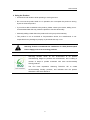
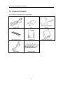
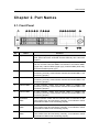
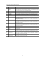
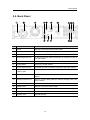
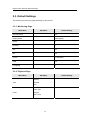
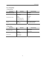
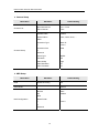
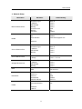
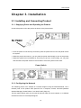
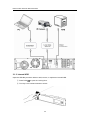
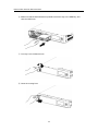
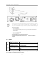
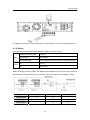
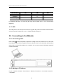
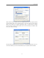
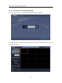
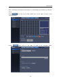
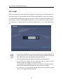
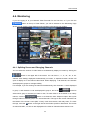
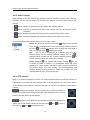
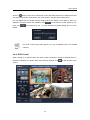
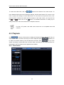
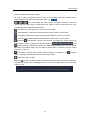
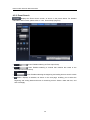
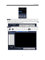
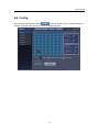
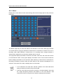
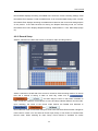
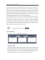
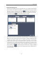
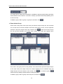
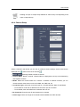
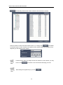
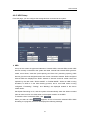
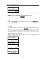
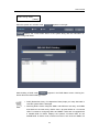
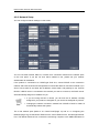

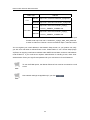
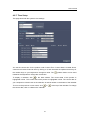
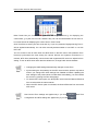
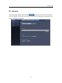
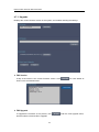
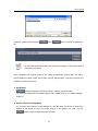
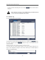
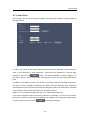
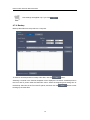
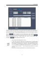
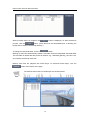

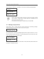
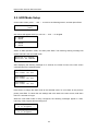
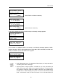
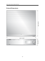

![User Manual [English]](http://vs1.manualzilla.com/store/data/005834880_1-d53398c0de391706aeb0ae49b4eb40a6-150x150.png)