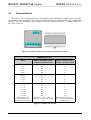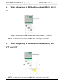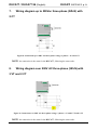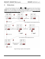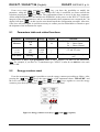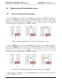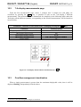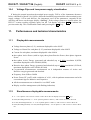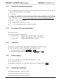
1
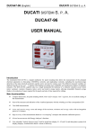
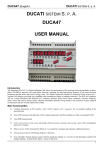
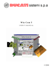
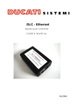
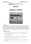
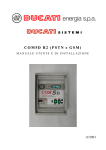
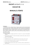
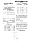
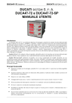
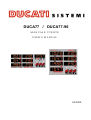
DUCA77 / DUCA77-96
MANUALE UTENTE
USER'S MANUAL
06/2004
DUCA77 / DUCA77 96 (English)
DUCATI SISTEMI S. p. A.
INDEX
1.
Introduction.............................................................................................................3
2.
Description..............................................................................................................4
3.
Dimensions and installation ....................................................................................5
4.
Notes for Wiring .....................................................................................................6
4.1
Terminal blocks ....................................................................................................................... 7
5.
Wiring diagram up to 500Vac three-phase (3Ø+N) with 3 CT...............................8
6.
Wiring diagram up to 500Vac three-phase (3Ø+N) with 3 VT and 3 CT...............8
7.
Wiring diagram up to 500Vac three-phase (3Ø+N) with 2 CT...............................9
8.
Wiring diagram over 500V AC three-phase (3Ø+N) with 3 VT and 2 CT.............9
9.
Setup menu .............................................................................................................10
9.1
Parameters table and related functions .................................................................................... 11
9.2
Energy counters reset............................................................................................................... 11
10. Measurements Visualisation menu .........................................................................12
10.1 Active and Reactive Energy pages .......................................................................................... 12
10.2 7-th display measurements page .............................................................................................. 13
10.3 Overflow management visualisation ....................................................................................... 13
10.4 Voltage Dips and Low-power-supply visualisation................................................................. 14
11. Performances and technical characteristics.............................................................14
11.1 Displayable measurements ...................................................................................................... 14
11.2 Simultaneous displayable measurements................................................................................. 14
11.3 Voltmeter and ammeter inputs................................................................................................. 15
11.4 Accuracy of the measurements ................................................................................................ 15
11.5 Interfaces.................................................................................................................................. 15
11.6 Power supply............................................................................................................................ 15
11.7 Operating conditions................................................................................................................ 15
11.8 Protection ................................................................................................................................. 16
11.9 Miscellaneous .......................................................................................................................... 16
11.10 Normative reference ................................................................................................................ 16
2
DUCA77 / DUCA77 96 (English)
DUCATI SISTEMI S. p. A.
Table of Figure
Figure 1: Front view of the 6-DIN rail mounting instrument and the 96x96mm panel mounting version............... 4
Figure 2: DUCA77 dimensions (DIN rail mounting version)........................................................................................ 5
Figure 3: Dimensions and panel-bore of the DUCA77-96 (96x96mm panel mounting version)................................ 5
Figure 4: Terminal blocks layout on the two instruments versions ............................................................................. 7
Figure 5: Terminal blocks table ...................................................................................................................................... 7
Figure 6: Connection up to 500V AC three-phase voltage, 3 phases + N with 3 CT................................................... 8
Figure 7: Connection over 500V AC three-phase voltage, 3 phases + N with 3 VT and 3 CT ................................... 8
Figure 8: Connection up to 500V AC three-phase voltage, 3 phases + N with 2 CT................................................... 9
Figure 9: Connection over 500V AC three-phase voltage, 3 phases + N with 3 VT and 2 CT ................................... 9
Figure 10: Pages sequence of the setup menu............................................................................................................... 10
Figure 11: Energy counters reset (keys “
” and “
” together) ...................................................................... 11
Figure 12: Generated and absorbed Active Energy counter page (key “
”) ....................................................... 12
”)................................................... 12
Figure 13: Generated and absorbed Reactive Energy counter page (key “
Figure 14: 7-th display measurements visualisation (key “
”) ............................................................................ 13
======================================================
1.
Introduction
This manual contains technical information and cautions for the user in order to assure a correct
use of the instrument and its good maintenance in safety conditions to obtain the best performance.
The installation of the instrument must be executed by qualified person after carefully reading
this manual.
This symbol identifies all the caution for a correct and safety use of instrument as well
as for the operator.
The manufacturer certifies that the instrument DUCA77 is made according to the
European Directive 89/336/EEC (EMC) and 73/23/EEC (LVD) and following
updates.
3
DUCA77 / DUCA77 96 (English)
2.
DUCATI SISTEMI S. p. A.
Description
The instrument DUCA77 is a DIN rail mounting (6 modules) instrument; the corresponding
96x96mm panel mounting version is named DUCA77-96. The DUCA77 is the “at-a-glance”
instrument, since provides the contemporary visualisation of the main three-phase electrical plants
parameters (3 voltages and 3 currents), including the three-phase Active Energy and the three-phase
Reactive Energy. The DUCA77 includes moreover four independents counters for active and
reactive energies, absorbed or generated from the user (co-generated energy measurements); in fact
it is a 4-quadrant instrument.
Its main feature is to provide immediately, through the visualisation on 7 displays with 4-digit
figures each, a complete description of the actual situation of the three-phase connected power line.
In fact, in the main screen, are visualised all the voltage and current values of the power line for
each phase, including the frequency. The DUCA77 can be connected to the medium voltage line,
since the ratio of the voltage and current transformer can be programmed up to display 9999Ampere
and 9999Volt maximum, while energies can be displayed with a maximum of 8 digits. The
DUCA77 provides moreover the recognition and visualisation of Voltage Dips occurrences or
situations of low-power-supply.
Figure 1: Front view of the 6-DIN rail mounting instrument and the 96x96mm panel mounting version
4
DUCA77 / DUCA77 96 (English)
3.
DUCATI SISTEMI S. p. A.
Dimensions and installation
For the two instrument’s dimensions refers to the following figures:
DIN RAIL MOUNTING MODEL
Figure 2: DUCA77 dimensions (DIN rail mounting version)
96 X 96mm PANEL MOUNTING MODEL: DIMENSIONS AND PANEL-BORE
Figure 3: Dimensions and panel-bore of the DUCA77-96 (96x96mm panel mounting version)
In the 96x96 panel mounting version there are two bushes used with a M3 dice in the back of the
instrument, used to install the instrument on the panel.
5
DUCA77 / DUCA77 96 (English)
4.
DUCATI SISTEMI S. p. A.
Notes for Wiring
General notes
MAKE ALL CONNECTIONS WITHOUT any VOLTAGE APPLIED TO THE
INSTRUMENT.
Voltage input
ALWAYS VERIFY THE CORRECT VOLTAGE INPUTS. BE SURE THIS IS
NOT EXCEEDING THE MAXIMUM VALUE SUITABLE FOR THIS
INSTRUMENT.
Make connections according to the wiring diagram, be careful to respect the correct phases
sequence.
Input current
ALWAYS VERIFY THE CORRECT CURRENT INPUTS. BE SURE THIS IS
NOT EXCEEDING THE MAXIMUM VALUE SUITABLE FOR THIS
INSTRUMENT.
Make connections according to the wiring diagram, be careful to respect the correct phases
sequence and current direction.
THE CURRENT TRANSDUCER INSIDE OF THE INSTRUMENT ARE
SHUNTS, THE NOMINAL CURRENT IS 5A AC RMS, THE MAXIMUM
CURRENT IS 10A AC (for 1 minute). BE CAREFUL: AVOID DIRECT
CONNECTIONS OF THE INSTRUMENT TO THE POWER LINE WITHOUT
THE CURRENT TRANSFORMERS - ALWAYS USE CTs.
BE CAREFUL: NEVER OPEN THE SECONDARY WINDING SIDE OF THE
CURRENT TRANSFORMER UNLESS THERE IS NO CURRENT ON THE
PRIMARY SIDE WIRES. IF THIS IS NOT POSSIBLE, MAKE A SHORT
CIRCUIT ON THE SECONDARY SIDE BEFORE OPENING THE CIRCUIT.
6
DUCA77 / DUCA77 96 (English)
4.1
DUCATI SISTEMI S. p. A.
Terminal blocks
The DUCA77-96 is equipped with two extractable terminal blocks M1 and M2 (wire screwing);
the maximum current rating is 16A, the connection is fitted for 2,5sqmm flexible wire (4sqmm non
flexible wire). The maximum rated voltage is 500Vrms, insulation 3kVrms / 1 minute (IMQ-UL),
fire class V0-UL94.
Figure 4: Terminal blocks layout on the two instruments versions
TERMINAL BLOCKS
Value
Power supply
0V
115V
230V
400V
Voltmeter inputs
( R ) L1
( S ) L2
( T ) L3
N
Secondary CT
L1 – S1
L1 – S2
L2 – S1
L2 – S2
L3 – S1
L3 – S2
Note: all the CT's S1
terminals must be
connected to the Neutral pin
DUCA77-96 (96x96 model)
Number of terminal block
DUCA77 (DIN rail model)
Number of terminal block
M2 – 4
M2 – 3
M2 – 2
M2 – 1
19
21
23
25
M1 – 10
M1 – 7
M1 – 4
M1 – 1
1
7
12
18
M1 – 8
M1 – 9
M1 – 5
M1 – 6
M1 – 2
M1 – 3
Note: M1 – 8, M1 – 5, M1 – 2
must be connected to the Neutral
pin
5
3
10
9
16
14
Note: the terminal blocks 5 –
10 – 16 must be connected to
the Neutral pin
Figure 5: Terminal blocks table
7
DUCA77 / DUCA77 96 (English)
5.
DUCATI SISTEMI S. p. A.
Wiring diagram up to 500Vac three-phase (3Ø+N) with 3
CT
Figure 6: Connection up to 500V AC three-phase voltage, 3 phases + N with 3 CT
NOTE: the connection is the same for the DUCA77, following the same order.
6.
Wiring diagram up to 500Vac three-phase (3Ø+N) with
3 VT and 3 CT
Figure 7: Connection over 500V AC three-phase voltage, 3 phases + N with 3 VT and 3 CT
NOTE: the connection is the same for the DUCA77, following the same order.
8
DUCA77 / DUCA77 96 (English)
7.
DUCATI SISTEMI S. p. A.
Wiring diagram up to 500Vac three-phase (3Ø+N) with
2 CT
Figure 8: Connection up to 500V AC three-phase voltage, 3 phases + N with 2 CT
NOTE: the connection is the same for the DUCA77, following the same order.
8.
Wiring diagram over 500V AC three-phase (3Ø+N) with
3 VT and 2 CT
Figure 9: Connection over 500V AC three-phase voltage, 3 phases + N with 3 VT and 2 CT
NOTE: the connection is the same for the DUCA77, following the same order.
9
DUCA77 / DUCA77 96 (English)
9.
DUCATI SISTEMI S. p. A.
Setup menu
After pressing contemporary the keys “
” and “
” the instrument enters the parameters
configuration menu, showing on the upper display “MEASURE” and on the lower display
“PROG”; the two central displays are clear. In the following figure (see Figure 10) it is shown the
interface for the panel mounting model DUCA77-96, remembering that it is the same for the
corresponding DIN rail mounting version ( DUCA77 ).
Figure 10: Pages sequence of the setup menu
10
DUCA77 / DUCA77 96 (English)
DUCATI SISTEMI S. p. A.
From every setup page, pressing the “
” key, you have the possibility to modify the
” or “
” keys. When the value is modified you must confirm the
parameter, using the “
selection pressing the “
” key again. The confirmation allows to access to the next parameter.
All the modified parameters are stored in the EEPROM. At the power on the DUCA77 verifies the
integrity of the stored parameters, and in case unfortunately these parameters are corrupted, the 7-th
”: in this case the user should repeat the configuration procedure. After this,
display will show “
if the error will recur again, it could be necessary to contact your local distributor or Ducati to agree
the shipment of the instrument for repair.
9.1
Parameters table and related functions
Parameter
Visualisation
Measure
LL
Ln
Ratio
CT ratio
VT ratio
ct.r
Ut.r
Par.SAVE
SAVIng…
Range
Default
LL
1÷4000
1÷100
Function
Voltage measurement mode
LL = Phase-Phase
Ln = Phase-Neutral
CT and VT ratio
1
1
Modifications saving and setup menu
exit
Note for CT and VT programmable ratio: in this parameter you must set the transformer
ratio. For example, if you have a CT transformer type "2000/5" it must be set 400 that is the ratio
2000/5=400.
9.2
Energy counters reset
From the measurement menu is possible to reset the energy counters proceeding as follow. After
pressing the “
” and “
” keys, the upper display of the instrument shows “MEASURE” and
the lower one shows “
”. Now press the “
” and “
” keys together to reset the energy
counters; press then repeatedly the “
” key to exit the setup menu.
Figure 11: Energy counters reset (keys “
” and “
” together)
11
DUCA77 / DUCA77 96 (English)
10.
10.1
DUCATI SISTEMI S. p. A.
Measurements Visualisation menu
Active and Reactive Energy pages
Press the “
” key to visualise the Absorbed Active Energy: the “kWh” led is turned-on
” key again to visualise the Generated Active Energy: the “kWh” led is
fixed. Press the “
flashing. The Active Energy is visualised on the first two displays, so to have up to 8 digits
” key again to return to the phase L1 voltage and
available for the value display. Press the “
current visualisation. The reading has a resolution of 0,1kWh.
Figure 12: Generated and absorbed Active Energy counter page (key “
”)
Press the “
” key to visualise the Absorbed Reactive Energy: the led “kVArh” is turned-on
fixed. Press the “
” key again to visualise the Generated Reactive Energy: the led “kVArh” is
flashing. The Reactive Energy is visualised on the second two displays, so to have up to 8 digits
available for the value display. Press the “
” key again to return to the phase L2 voltage and
current visualisation. The reading has a resolution of 0,1kVArh.
Figure 13: Generated and absorbed Reactive Energy counter page (key “
”)
Note: During the visualisation of the Co-generated Energy, the measurement units kWh o
kVArh are flashing continuously.
12
DUCA77 / DUCA77 96 (English)
10.2
DUCATI SISTEMI S. p. A.
7-th display measurements page
From the first measurements page, where 3 voltages and 3 currents for each phase are
” key, is possible to scan on the 7-th display 5 different
visualised, by pressing the “
measurements. This measurements are summarised for simplicity in the following table (under the
7th display all the different symbols, corresponding to the selected measurement, will be turned-on
in succession):
Parameters visualised in succession on the 7-th display pressing the “
Parameter
Frequency of the three-phase electrical line
Three-phase Active Power
Three-phase Reactive Power
Three-phase Apparent Power
Power Factor
Visualised symbol
Hz
kW
kVAr
kW e kVAr (turned-on together)
PF
Figure 14: 7-th display measurements visualisation (key “
10.3
” key
”)
Overflow management visualisation
When a single measurement is greater than the maximum displayable value, then it will be
displayed flashingi independently from the others.
i
In case of overflow, the less significant digits are truncated
13
DUCA77 / DUCA77 96 (English)
10.4
DUCATI SISTEMI S. p. A.
Voltage Dips and Low-power-supply visualisation
If during the normal operation the nominal power supply 230Vac of the instrument decreases
below a threshold of about 180÷190Vac (different thresholds proportional the other nominal power
supply voltages 115Vac and 400Vac), the instrument saves all the parameters, suspends all the
activities and shows on the upper display “SAVing”. If the voltage restores to normal values, the
DUCA77 restarts working regularly again, but the 7-th display will show Roff to indicate the
previous mains dip. This visualisation remain until pressing the “
” key.
11.
11.1
Performances and technical characteristics
Displayable measurements
♦ Voltage between phases (L-L), maximum displayable value 9999V
♦ Voltage-to-Neutral for each phase (L-N), maximum displayable value 9999V
♦ Current for each phase, maximum displayable value 9999A
♦ three-phase Active Power (with its sign), three-phase Reactive Power, three-phase Apparent
Power
♦ three-phase Active Energy (generated and absorbed) up to 8 digit (resolution 0,1kWh,
maximum displayable value 9999999,9kWh)
♦ Reactive three-phase Energy (generated and absorbed) up to 8 digit (resolution 0,1kVArh,
maximum displayable value 999999,9kVArh)
♦ Co-generation measurements: measurement on 4 independent counters of Active and
Reactive energies generated and absorbed
♦ Frequency from 30Hz to 200Hz
♦ Power Factor PF (cosFI) with resolution of ±0,01, with 4-quadrant measurement and with
conventional sign for Inductive and Capacitive
♦ All the measurements are evaluated in “true RMS” mode
♦ Display overflow management (with flashing indication)
11.2
Simultaneous displayable measurements
♦ V – A on 3 phases + kW or kVAr or kVA or Hz or PF on the 7-th display (scan with “
” key)
♦ kWh (absorbed/generated) + V – A for 2 phases (phase L2 and L3) + kW or kVAr or kVA or Hz or PF
♦ kVArh (absorbed/generated) + V – A for 2 phases (phase L1 and L3) + kW or kVAr or kVA or Hz or PF
♦ kWh (absorbed/generated) + kVArh (absorbed/generated) + V-A for phase L3 + kW or kVAr or kVA or Hz or
PF
14
DUCA77 / DUCA77 96 (English)
11.3
DUCATI SISTEMI S. p. A.
Voltmeter and ammeter inputs
♦ 3 for voltage in the range 20÷300Vrms (L-N), maximum non destructive 1000Vrms for one
minute; input load 0,08VA for each phase
♦ 1 for Neutral
♦ 3 couples (S1 and S2) for current in the range 20mA÷5Arms, permanent overload 6Arms;
maximum non destructive 10Aca for one minute; burden/dispersed power 0,025VA for each
input with Imax = 5Arms, current inputs through internal shunts and using external CTs
♦ Insulation = 2,2kV for one minute
♦ VT = programmable ratio from 1 to 100
♦ CT = "../5A" with programmable ratio from 1 to 4000
11.4
Accuracy of the measurements
♦ Accuracy Class = 1
♦ Accuracy of primary measurements:
√ Voltage 0,5%
±1 digit in the range 100÷440VLL (58÷254VLN)
√
1%
±1 digit in the range 440÷500VLL (254÷288VLN)
√ Current 0,5%
±1 digit in the range 100mA÷5Arms
11.5
Interfaces
♦ 7 display / 7 segment with 4-digit figure each (height of characters 10mm)
♦ 3 user friendly keys with incremental autoscroll speed to scan:
,
and
√ the measurements: indication
√ setup the configuration parameters: indication
11.6
,
and
Power supply
♦ 115 – 230 – 400 Vac ±15%, 45÷65Hz, absorbed power < 7VA
♦ Fit external fuse T0,1A
♦ Recognition and display of voltage dips and low-power supply (function Roff)
11.7
Operating conditions
♦ Working temperature: from 0°C to 50°C
♦ Storage temperature: from -10°C to 60°C
♦ Relative humidity 90% without condense
15
DUCA77 / DUCA77 96 (English)
11.8
DUCATI SISTEMI S. p. A.
Protection
♦ IP50 on the front panel
♦ IP20 on the terminal blocks
11.9
Miscellaneous
♦ Possibility of 96x96 panel mounting version or DIN rail mounting version (6 modules)
with the same features
♦ Connections with extractable terminal blocks IMQ-UL, fire class V0-UL94 (only
model 96x96)
√ maximum 16A
√ 2,5sqmm flexible wire (4sqmm non flexible wire)
√ insulation 500Vrms between terminals
√ 3kVrms / 1 minute
♦ Case in NORYL, fire class UL94 V2
√ Front panel in polyester with texturing treatment
♦ Dimensions:
√ 96x96model
=
96mm x 96mm x 75mm (LxHxW)
√ DIN rail model =
105mm x 90mm x 73mm (LxHxW)
♦ Weight: about 350g
11.10
Normative reference
The instrument is compliant with the following EU standard directives:
♦ ELECTRICAL SAFETY – Low Voltage Directive No. 73/23/CEE
♦ ELECTROMAGNETIC COMPATIBILITY – Directive No. 89/336/CEE
16
DUCA77 / DUCA77 96 (English)
DUCATI SISTEMI S. p. A.
DUCATI Sistemi S. p. A. denies any responsibility for damage or personal injury caused by
the improper or erroneous use of this equipment.
This documentation may be subject to modification without prior notice.
This manual refers to the firmware versions released in April 2004 and successive.
Documentation code: DUCA77_V14_ENG.doc – Version 1.4 – June 2004.
Via Ronzani 47, - 40033 Casalecchio di Reno (Bologna) - Italy
Tel.: +39- 051 6116.611 - Fax: +39-051 6116.690
WEB: www.ducatisistemi. com
e-mail (Commerc.) = [email protected] // e-mail (Technical) = [email protected]
17