1
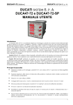
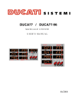
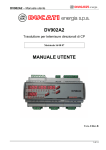
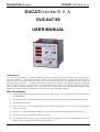
DUCA47-96 (English)
DUCATI SISTEMI S. p. A.
DUCATI SISTEMI S. P. A.
DUCA47-96
USER MANUAL
Introduction
The instrument DUCA47-96 is a digital multimeter for panel mounting that allows the measurement of the principal
electrical parameters in three-phase 230/400Vac networks and single-phase networks, including the max/min/average
detection of the main electrical parameters and the active and reactive energy count. The different measured variables are
displayed locally on four red
7-segment LED displays providing easy readability and simultaneous display of multiples
measures. The DUCA47-96 combines also (in a single instrument) the functions of a voltmeter, ammeter, power factor
meter, wattmeter, varmeter, frequency meter, active and reactive energy meters, allowing remarkable financial savings
thanks to the reduction of space required for the panels and also of time required for cabling.
Main functionalities
•
Compact dimensions, for panel mounting 96x96, with 4 LED’s display with 7 segments, for an excellent reading of
the measurements
•
Scan of the measures and indication of the visualised parameter with the switching on of the correspondent LED
•
True RMS measurements
•
Active and reactive energy count and storage of the maximum, minimum and average values with an integration
period of 15 minutes
•
High accuracy of the measurements thanks to “oversampling” tecniques and automatic calibration process
•
68 total measurements with Energy-Analyser’s functions
•
User selectable “default displayed page” both for single line (display L1, L2 and L3) and three-phase system (4-th
display) displays, visualised after about 1 minute of inactivity
1
DUCA47-96 (English)
•
DUCATI SISTEMI S. p. A.
Automatic detection of CTs current flow direction for an easy installation of the system. If the operator makes a
mistake during CTs installation (inversion’s error), at power-up the instrument detects automatically the correct
flow of the current, adjusting the error, in an independent way for each phase
•
2 time counters (hours and minutes). The first counter “t1”, resetable from the configuration menu, increases
regularly and can be use as instrument’s working time indicator; the second counter “t2” continue counting down
from the set value and can be use for maintenance reminder when it reaches the 0 value (than it decreases with
negative values, showing the delay from the expiry programmed time)
Assembly instructions
a)
Set the device in the hollow frame and push till the surfaces touch one another
b) Lock the red spring mounts in the locking slids (1)
c)
Push the red spring mounts (2) to lock the frame to the device (to unlock the springs pull slightly the spring
vertical edge in order to unlock the blocking tooth and slide back the spring itself)
Terminal board connection and examples of connections
Pin
Description
Power Supply
0
115
230
Pin
Description
Current Inputs
0 ~ Power-supply
115 ~ Power-supply
230 ~ Power-supply
S2-I1
S1-I1 (*)
S2-I2
S1-I2 (*)
S2-I3
S1-I3 (*)
Pin
Description
Voltage Inputs
S2 – input I1
S1 – input I1
S2 – input I2
S1 – input I2
S2 – input I3
S1 – input I3
N
L1
L2
L3
N – Voltmeter inputs
L1 – Voltmeter inputs
L2 – Voltmeter inputs
L3 – Voltmeter inputs
(*) In case of connection of the secundary of the CTs to Earth, only the pins S1-I1, S1-I2 and S1-I3 must be connect to
Earth.
NOTE: the CURRENT INPUTS terminal block is removable-type terminal fixed on the instrument with screws, we
advise to screw down the terminal block after the installation to lock it and avoid unwanted extractions.
2
DUCA47-96 (English)
DUCATI SISTEMI S. p. A.
Three-phase direct connection with neutral
Single-phase direct connection
Three-phase indirect conn. with neutral with 3VTs and 3 CTs
NOTE: in single-phase connection the “Threephase” measurements are not significant.
NOTE: the use of the VTs in “star” connection is optional if
the user want lower voltages on the electric measurement
panel or need a further galvanic insulation.
3
DUCA47-96 (English)
DUCATI SISTEMI S. p. A.
Three-phase indirect conn. without neutral with 3VTs and 3 CTs
NOTE: the use of the VTs in “delta” connection is optional
if the user want lower voltages on the electric measurement
panel or need a further galvanic insulation.In this cases is
not allowed the connection of any of the phases of the VT’s
secundary to Earth.
Instrument’s description
Three-phase indirect conn. without neutral with 2CTs and 2VTs
NOTE: the use of the VTs is optional if the user want lower
voltages on the electric measurement panel or need a
further galvanic insulation.In this cases is not allowed the
connection of any of the phases of the VT’s secundary to
Earth.
5
9
1
7
8
3
6
2
•
4
Display L1, L2, L3 for the visualisation of the electrical parameters of every phase, of the energy counters
and the time counters (energy and time counters are visualised in sequence on the displays L1, L2 e L3; L1 holding
the most significant digits and L3 the less significant digits)
•
4-th display for the visualisation of the electrical parameters of the three-phase system
•
Key for the scan of the electrical parameters for each phase and the energy counters, visualised on the
displays L1, L2, L3 (
•
•
), if you press-and-hold-down the previous page will be displayed
Key for the scan of the three-phase electrical parameters, visualised on the 4-th display (
counters, if you press-and-hold-down the previous page will be displayed
) and the time
9 LEDs for the indication of the electrical parameters displayed on the three displays L1, L2, L3 (
)
4
DUCA47-96 (English)
DUCATI SISTEMI S. p. A.
•
7 LEDs for the indication of the electrical parameters displayed on the 4-th display (
•
Key for set out the visualisation of maximum values of the electrical parameters (LED MAX
on), of minimum values (LED MIN
)
switched
switched on) and average values (calculation period of 15 minutes)
switched on). When the LED, wich shows the selected
(AVERAGE, simultaneously LED MIN and MAX
type of visualisation, is switched on, it will be possible to scan in sequence the different electrical parameters by
pressing
•
and
keys
LED for the identification of the visualised electrical parameters scale on both instrument’s
displays
and
(K = kilo, parameter x 1.000, M = mega, parameter x 1.000.000)
•
LED for the identification of the max/min/average values displayed on the displays
•
+
e
Press together allow the access to the configuration menu (setup)
Instrument’s functionalities
The indication Σ refers to the three-phase measurements of the correspondent parameter.
MEASURED PARAMETERS
Phase-to-Phase Voltage (VL-L)
VL1-L2, VL2-L3, VL3-L1
Line and Three-Phase Voltage (VL-N e ΣV)
VL1-N, VL2-N, VL3-N, ΣV
Line and Three-Phase Current (A e ΣA)
I1, I2, I3, ΣI
Frequency
Hz
Line and Three-Phase Active Power (W and ΣW)
W 1, W 2, W 3, Σ W
Line and Three-Phase Reactive Power (VAr and ΣVAr)
VAr1, VAr2, VAr3, ΣVAr
Line and Three-Phase Apparent Power (VA and ΣVA)
VA1, VA2, VA3, ΣVA
Line and Three-Phase Power-Factor/cosϕ, with indication of the PF1, PF2, PF3, ΣPF
conventional sign (+ = Inductive Load, - = Capacitive Load)
Active and Reactive Line and Three-Phase Energy counters
kWh-L1, kWh-L2, kWh-L3, ΣkWh-3P
(visualisation concatenated on the displays L1, L2 e L3)
kVArh-L1, kVArh-L2, kVArh-L3, ΣkVArh-3P
MAXIMUM DISPLAYED VALUES
Line Voltage (VL-N)
VL1-N, VL2-N, VL3-N (MAX)
Line Current (A)
I1, I2, I3 (MAX)
Line and Three-Phase Active Power (W and ΣW)
W1, W2, W3, ΣW (MAX)
Line and Three-Phase Reactive Power (VAr and ΣVAr)
VAr1, VAr2, VAr3, ΣVAr (MAX)
Line and Three-Phase Apparent Power (VA and ΣVA)
VA1, VA2, VA3, ΣVA (MAX)
MINIMUM DISPLAYED VALUES
Line Voltage (VL-N)
VL1-N, VL2-N, VL3-N (MIN)
Line Current (A)
I1, I2, I3 (MIN)
Three-Phase Active Power (Σ
ΣW)
ΣW (MIN)
5
DUCA47-96 (English)
DUCATI SISTEMI S. p. A.
Three-Phase Reactive Power (Σ
ΣVAr)
ΣVAr (MIN)
Three-Phase Apparent Power (Σ
ΣVA)
ΣVA (MIN)
AVERAGE DISPLAYED VALUES (INTEGRATION PERIOD 15 MINUTES)
Line and Three-Phase Active Power (W and ΣW)
W1, W2, W3, ΣW (AVG)
Line and Three-Phase Reactive Power (VAr and ΣVAr)
VAr1, VAr2, VA3, ΣVAr (AVG)
Line and Three-Phase Apparent Power (VA and ΣVA)
VA1, VA2, VA3, ΣVA (AVG)
TIME COUNTERS
Hours counter (hours and minutes) “free-running” resetable from setup menu, variable in the range 0 ÷ 10000000 hours
(visualisation concatenated on the displays L1, L2 e L3)
Hours counter (hours and minutes) “count-down” for maintenance reminder (visualisation concatenated on the displays L1,
L2 e L3), selectable in the range 1 ÷ 32000 hours (when the counter reaches zero than it shows negative values until 32000, indicating the delay from the expiry programmed time)
NOTE: Sometimes, when installing the device at the first time, due certain events or wrong maneuvers, or in case of not
efficient non-volatile memory (E2prom), the instrument stops and a page with the writing “INI” on the first three displays
will be displayed, following by an internal identification code. Pressing any key will set the default parameters, which may
be changed by the user as required. In any case contact always the Ducati assistance for instrument’s maintenance.
Instrument’s configuration menu (setup)
To access to the instrument’s configuration menu press together
visualised on the first three displays, press the
and
keys, when the writing “SETUP” is
key.
In the configuration menu the keys have the following function:
•
•
•
Increases the selected parameter (two-speed autorepeat if hold down); in the reset pages it allows the “reset”
of the selected parameters
Decreases the selected parameter (two-speed autorepeat if hold down)
Confirms modifications and steps to the next page; if you press-and-hold-down, the previous page will be
displayed
The displayed pages (in sequence) in the configuration menu are the following:
•
•
•
“Ct rAt”: set of the transformation ratio of CTs (KA), variable in the range 1 ÷ 1250, factory default value 1. For
example if you have a 800/5A CT, you must insert the value 160
“Ut rAt”: set of the transformation ratio VT (KV), variable in the range 1 ÷ 500, factory default value 1
“PAG 1.2.3.” e “PAG 4.”: number setting of the default displayed page, 0 ÷ 15 on the first three displays, factory
default value 1; 0 ÷ 7 on the 4-th display, factory default value 1; 0 = it remains the last selected page
•
“t2”: setting in hours of the count-down value of the hours counter t2, factory default value 8760.00 (1 year)
•
“rESEt PEA” (PEAK = Peak Values): maximum and minimum values reset (to reset see note below)
•
“rESEt AUG” (AVG = Average): average values reset (to reset see note below)
•
“rESEt En” (En = Energies): energy counters reset (to reset see note below)
•
“rESEt t1”: hours counter t1 reset (to reset see note below)
•
“rESEt ALL”: restore the default configuration and resets all the parameters (min/max values, average values,
energies, t1 counter) - (to reset see note below)
6
DUCA47-96 (English)
•
DUCATI SISTEMI S. p. A.
“rEL”: instrument’s firmware revision
NOTE:
to perform the previous described resets, from the correspondent page, hold down for some seconds
the
key until the visualisation of the “-C- -L- -r-” writing appears on the first three displays
the peak values, the average values, the energy counters and the values of the counters t1 e t2 are maintained in
the instrument memory in case of power failures
Technical characteristics
DIMENSIONS
Panel mounting model:
96 mm x 96 mm x 103 mm (LxHxW) – IEC 61554
WEIGHT
About 500g
PROTECTION
IP50 on the front panel
IP20 on the terminal blocks
POWER-SUPPLY
Voltage
Frequency
Power consumption
Fuse
45 ÷ 65Hz
< 6VA
Fit external fuse T0,1A
230V rms (+15% -10%)
240V rms (+10% -15%)
115V rms (+15% -10%)
120V rms (+10% -15%)
VOLTMETER INPUTS
Range
10 ÷ 500V rms (L-N)
Max non-destructive value
550V rms
L-N input impedance
Greater than 8MΩ
AMMETER INPUTS (USE ALWAYS EXTERNAL CTs)
Range
50mA ÷ 5A rms
Overload
1,1 permanent
Max dispersed power (with Imax = 5A rms), for each 1,4VA
phase input
Type of measurement
Current inputs through internal shunts and using external CTs
Direction of CTs current
Detection and automatic adjustment at power up, independent
for each phase
ACCURACY OF THE MEASUREMENT
Voltages
±0,5% F.S. ±1 digit in the range 10Vac÷500Vac rms VL-N
Currents
±0,5% F.S. ±1 digit in the range 50mA÷5A rms
Active power
±1% ±0,1% F.S. (from cosφ = 0,3 Ind. to cosφ = -0,3 Cap.)
Frequency
40.0 ÷ 99.9Hz: ±0,2% ±0,1Hz
100 ÷ 500Hz:
±0,2% ±1Hz
7
DUCA47-96 (English)
DUCATI SISTEMI S. p. A.
ENERGY COUNT
Maximum value for the single-phase energy
4294,9 MWh (MVArh) with KA = KV = 1
Maximum value for the three-phase energy
4294,9 MWh (MVArh) with KA = KV = 1
Accuracy
Class 1
OPERATIVE CONDITIONS
Operating temperature
0°C ÷ 50°C
Storage temperature
-10°C ÷ 60°C
Relative humidity
90% max. (without condense) at 40°C
REFERENCE NORMATIVES
LOW VOLTAGE – EC directive No. 73/23/CEE: compliance with EN 61010-1 regarding hygroscopic pre-conditioning,
dielectric rigidity and residual voltage
ELECTROMAGNETIC COMPATIBILITY – EC directive No. 89/336/CEE: compliance with standard EN61326-1
CONFIGURATION MENU
Parameters
Possible values
Factory default
VT transformation ratio
1 ÷ 500
1
CT transformation ratio
1 ÷ 1250
1
0 ÷ 15
1
PAG 1.2.3. (default page for displays L1,
L2 and L3)
PAG 4. (default page for the 4-th
display)
“Free-running” counter t1 (hours and
(0 = it remains the last displayed page)
0÷7
1
(0 = it remains the last displayed page)
The counter can be reset from the configuration menu
The counter work in the range:
0 ÷ 10000000 (hours)
minutes)
(about 1140 years)
“Count-down” counter t2 (hours and
Initial set in hours: 1 ÷ 32000 (about 3,5 years)
(1 year)
minutes)
Calculation period for mean values
8760 hours
-
15 minutes
(minutes)
DUCATI Sistemi S.p.A. shall not accept no liability for damage or personal injury arising from incorrect or improper
use of its equipment.
In line with a policy of continuous improvement, DUCATI Sistemi S.p.A. reserves the right to implement changes to
this manual without prior notice.
Document code: DUCA47-96_V0RD_ENG.doc - Version 0, Revision D – May 2008
Via M. E. Lepido, 182 – 40132 Bologna – Italia
Tel.: +39 – 051 6411511 – Fax: +39 – 051 6411690
WEB: www.ducatisistemi. com
E – mail (Commerc.) = [email protected] // E – mail (Technical) = [email protected]
8