1
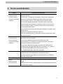
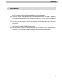
Machine Automation Controller NJ-series
EtherCAT
Connection Guide
OMRON Corporation
GRT1-ECT SmartSlice
P524-E1-01
About Intellectual Property Right and Trademarks
Microsoft product screen shots reprinted with permission from Microsoft Corporation.
Windows is a registered trademark of Microsoft Corporation in the USA and other countries.
EtherCAT® is registered trademark and patented technology, licensed by Beckhoff Automation
GmbH, Germany.
Company names and product names in this document are the trademarks or registered
trademarks of their respective companies.
Table of Contents
1.
Related Manuals ........................................................................................ 1
2.
Terms and Definition ................................................................................. 2
3.
Remarks ..................................................................................................... 3
4.
Overview .................................................................................................... 5
5.
Applicable Devices and Support Software.............................................. 6
6.
7.
8.
5.1.
Applicable Devices............................................................................. 6
5.2.
Device Configuration.......................................................................... 7
EtherCAT Settings ..................................................................................... 9
6.1.
EtherCAT Communications Settings .................................................. 9
6.2.
Assignment of EtherCAT Communications ........................................ 9
Connection Procedure .............................................................................11
7.1.
Work Flow .........................................................................................11
7.2.
Setting Up the SmartSlice ................................................................ 12
7.3.
Setting Up the Controller.................................................................. 16
7.4.
Connection Status Check................................................................. 28
Initialization Method ................................................................................ 33
8.1.
9.
Controller ......................................................................................... 33
Revision History ...................................................................................... 34
1. Related Manuals
1. Related Manuals
The table below lists the manuals related to this document.
To ensure system safety, make sure to always read and heed the information provided in all
Safety Precautions, Precautions for Safe Use, and Precaution for Correct Use of manuals for
each device which is used in the system.
Cat. No.
W500
Model
NJ501-[][][][]
Manual name
NJ-series CPU Unit Hardware User's Manual
NJ301-[][][][]
W501
NJ501-[][][][]
NJ-series CPU Unit Software User's Manual
NJ301-[][][][]
W505
NJ501-[][][][]
NJ-series CPU Unit Built-in EtherCAT Port User's
NJ301-[][][][]
Manual
W504
SYSMAC-SE2[][][]
Sysmac Studio Version 1 Operation Manual
W455
GRT1 series
SmartSlice GRT1 Series Slice I/O Units Operation
Manual
W18E
GRT1-ECT
GRT1-series
EtherCAT Communication Unit Operation Manual
1
2. Terms and Definition
2. Terms and Definition
Terms
Explanation and Definition
PDO
This method is used for cyclic data exchange between the master unit
Communications
and the slave units
(Communications
PDO data (i.e., I/O data that is mapped to PDOs) that is allocated in
using Process Data
advance is refreshed periodically each EtherCAT process data
Objects)
communications cycle (i.e., the period of primary periodic task).
The NJ-series Machine Automation Controller uses process data
communications for commands to refresh I/O data in a fixed control
period, including I/O data for EtherCAT Slave Units, and the position
control data for Servomotors.
It is accessed from the NJ-series Machine Automation Controller in the
following ways.
•With device variables for EtherCAT slave I/O
•With Axis Variables for Servo Drive and encoder input slaves to which
assigned as an axis.
SDO
This method is used to read and write the specified slave unit data from
Communications
the master unit when required.
(Communications
The NJ-series Machine Automation Controller uses SDO
using Service Data
communications for commands to read and write data, such as for
Objects)
parameter transfers, at specified times.
The NJ-series Machine Automation Controller can read/write the
specified slave data (parameters and error information, etc.) with the
EC_CoESDORead (Read CoE SDO) instruction or the
EC_CoESDOWrite (Write CoE SDO) instruction.
Slave Unit
There are various types of slaves such as Servo Drives that handle
position data and I/O terminals that control the bit signals.
The slave receives output data sent from the master, and transmits
input data to the master.
Node address
An address to identify the unit connected to the EtherCAT.
ESI file
The ESI files contain information unique to the EtherCAT slaves in XML
(EtherCAT Slave
format.
Information file)
Install an ESI file into the Sysmac Studio, to allocate slave process data
and make other settings.
2
3. Remarks
3. Remarks
(1) Understand the specifications of devices used in the system. Allow some margin for
ratings and performance. Provide safety measures, such as installing safety circuit in
order to ensure safety and minimize the risks of abnormal operation.
(2) To ensure system safety, always read and heed the information provided in all Safety
Precautions, Precautions for Safe Use, and Precaution for Correct Use of manuals for
each device used in the system.
(3) The users are encouraged to confirm the standards and regulations that the system must
conform to.
(4) It is prohibited to copy, to reproduce, and to distribute a part of or whole of this document
without the permission of OMRON Corporation.
(5) This document provides the latest information as of December 2012. The information
contained in this document is subject to change for improvement without notice.
3
3. Remarks
The following notation is used in this document.
Precautions for Safe Use
Indicates precautions on what to do and what not to do to ensure using the product safely.
Precautions for Correct Use
Indicates precautions on what to do and what not to do to ensure proper operation and
performance.
Additional Information
Provides useful information.
Additional information to increase understanding or make operation easier.
4
4. Overview
4. Overview
This document describes the procedure for connecting the SmartSlice (GRT1-ECT) of
OMRON Corporation (hereinafter referred to as OMRON) to NJ-series Machine Automation
Controller (hereinafter referred to as Controller) on the EtherCAT and provides the procedure
for checking their connection.
Refer to Section 7 Connection Procedure to understand the setting method and key points to
connect the devices via EtherCAT.
5
5. Applicable Devices and Support Software
5. Applicable Devices and Support Software
5.1. Applicable Devices
The applicable devices are give below.
Manufacturer
OMRON
Name
NJ series CPU Unit
OMRON
SmartSlice EtherCAT
Communications Unit
SmartSlice Slice I/O Unit
Digital Input Unit
OMRON
Digital Output Unit
Analog Input Unit
Analog Output Unit
Temperature Input Unit
Counter Unit
Positioning Unit
Turnback Unit
I/O Power Feed Unit
I/O Power Connection Unit
Model
NJ501-[][][][]
NJ301-[][][][]
GRT1-ECT
GRT1-ID[](-1)
GRT1-IA4-[]
GRT1-OD[](-1)
GRT1-ROS2
GRT1-AD2
GRT1-DA2[]
GRT1-TS2P(K)
GRT1-CT1(-1)
GRT1-CP1-L
GRT1-TBR
GRT1-TBL
GRT1-PD2[]
GRT1-PD8(-1)
GRT1-PC8(-1)
Version
Versions
listed in
Section 5.2
and higher
versions
Additional Information
As applicable devices above, the devices listed in Section 5.2. are actually used in this
document to check the connection. When using devices not listed in Section 5.2, check the
connection by referring to the procedure in this document.
Additional Information
This document describes the procedure to establish the network connection. It does not
provide information about operation, installation nor wiring method of each device.
For details on the products (other than communication connection procedures) listed above,
refer to the manuals for the corresponding products or contact your OMRON representative.
Additional Information
You can connect devices with the versions listed in Section 5.2 or higher versions.
For devices whose versions are not listed in Section 5.2, versions are not managed or there
is no version restriction.
To connect a device whose model number is not listed in Section 5.2, use the same version
of the device that is listed.
6
5. Applicable Devices and Support Software
5.2. Device Configuration
The hardware components to reproduce the connection procedure in this document are as
follows.
Personal computer
(Sysmac Studio installed
OS: Windows7)
NJ501-1500
(Built-in EtherCAT port)
GRT1-ECT+
SmartSlice Units
Ethernet cable
USB cable
Manufacturer
OMRON
OMRON
Name
CPU Unit
(Built-in EtherCAT port)
Power Supply Unit
Sysmac Studio
Personal computer (OS:Windows7)
USB cable
(USB 2.0 type B connector)
Ethernet cable (with industrial
Ethernet connector)
SmartSlice EtherCAT
Communication Unit
SmartSlice Digital Input Unit
OMRON
OMRON
OMRON
OMRON
SmartSlice Analog Input Unit
SmartSlice Digital Output Unit
SmartSlice Analog Output Unit
SmartSlice End Unit
OMRON
OMRON
OMRON
OMRON
Model
NJ501-1500
NJ1W-PA3001
SYSMAC-SE2[][][]
-
Version
Ver.1.03
Ver.1.04
XS5W-T421-[]M[]-K
GRT1-ECT
Ver.2.1
GRT1-ID8
GRT1-ID4
GRT1-AD2
GRT1-OD4
GRT1-DA2V
GRT1-END
Precautions for Correct Use
The connection line of EtherCAT communication cannot be shared with other networks, such
as Ethernet or EtherNet/IP.
The switching hub for Ethernet cannot be used for EtherCAT.
Please use the cable of Category 5 or higher, double-shielded with aluminum tape and
braided shielding and the shielded connector of Category 5 or higher.
Connect the cable shield to the connector hood at both ends of the cable.
Precautions for Correct Use
Update the Sysmac Studio to the version specified in this section or higher version using the
auto update function.
If a version not specified in this section is used, the procedures described in Section 7 and
subsequent sections may not be applicable. In that case, use the equivalent procedures
described in the Sysmac Studio Version 1 Operation Manual (Cat.No. W504).
7
5. Applicable Devices and Support Software
Additional Information
For information on the specifications of the Ethernet cable and network wring, refer to Section
4 EtherCAT Network Wiring in the NJ-series CPU Unit Built-in EtherCAT Port User's Manual
(Cat. No. W505).
Additional Information
The system configuration in this document uses USB for the connection between the
personal computer and the Controller. For information on how to install a USB driver, refer to
A-1 Driver Installation for Direct USB Cable Connection of the Sysmac Studio Version 1
Operation Manual (Cat.No. W504).
8
6. EtherCAT Settings
6. EtherCAT Settings
This section provides specifications such as communications parameters and variable names
that are defined in this document.
Hereinafter, the SmartSlice is referred to as the “destination device” or “Slave Unit" in some
descriptions.
6.1. EtherCAT Communications Settings
The setting required for EtherCAT communications is as follows.
GRT1-ECT
Node address
01
6.2. Assignment of EtherCAT Communications
The following table shows the arrangement of the SmartSlice I/O Units.
Unit No.
#1
#2
#3
#4
#5
Unit Type
EtherCAT Unit
Digital
Digital
Analog
Digital
Analog
Input
Input
Input
Output
Output
Unit
Unit
Unit
Unit
Unit
Model
GRT1-ECT
GRT1-I GRT1-I GRT1GRT1GRT1D8
D4
AD2
OD4
DA2V
End
Unit
GRT1END
I/O range setting of the Analog I/O Units
GRT1-AD2
GRT1-DA2V
I/O range
0 to 5V (Default)
0 to 5V (Default)
I/O range setting method
ON: Set with the DIP switch.
ON: Set with the DIP switch.
The device variables of the destination device are allocated to Controller's device variables.
The relationship between the device data and the device variables is shown below.
■Output area (Controller → Destination device)
Destination device data
Device variable name
Data type
#4 GRT1-OD4 Output 0
E001_DO001
BOOL
#4 GRT1-OD4 Output 1
E001_DO002
BOOL
#4 GRT1-OD4 Output 2
E001_DO003
BOOL
#4 GRT1-OD4 Output 3
E001_DO004
BOOL
#5 GRT1-DA2V Output 0
E001_AO001
INT
#5 GRT1-DA2V Output 1
E001_AO002
INT
9
6. EtherCAT Settings
■Input area (Controller ← Destination device)
Destination device data
Global variable name
Data type
#1 GRT1-ID8 Input 0
E001_DI001
BOOL
#1 GRT1-ID8 Input 1
E001_DI002
BOOL
#1 GRT1-ID8 Input 2
E001_DI003
BOOL
#1 GRT1-ID8 Input 3
E001_DI004
BOOL
#1 GRT1-ID8 Input 4
E001_DI005
BOOL
#1 GRT1-ID8 Input 5
E001_DI006
BOOL
#1 GRT1-ID8 Input 6
E001_DI007
BOOL
#1 GRT1-ID8 Input 7
E001_DI008
BOOL
#2 GRT1-ID4 Input 0
E001_DI009
BOOL
#2 GRT1-ID4 Input 1
E001_DI010
BOOL
#2 GRT1-ID4 Input 2
E001_DI011
BOOL
#2 GRT1-ID4 Input 3
E001_DI012
BOOL
#3 GRT1-AD2 Input 0
E001_AI001
INT
#3 GRT1-AD2 Input 1
E001_AI002
INT
■Details of the status allocation (Controller ← Destination device)
Destination device data
Global variable name
Communications Unit status
E001_Communication_Unit_Status
WORD
E001_Bus_Communication_Error
BOOL
E001_Unit_Warning
BOOL
Slice I/O Unit alarm flag
E001_Unit_Alarm
BOOL
Unit maintenance flag
E001_Unit_Maintenance
BOOL
E001_Restore_Monitor
BOOL
E001_Unit_Error
BOOL
E001_Refreshing
BOOL
Slice I/O Bus
communication error flag
Slice I/O Unit warning
flag
Automatic restore
monitor flag
Communication Unit
error flag
I/O refreshing flag
Data type
10
7. Connection Procedure
7. Connection Procedure
This section describes the procedure for connecting the Controller to the SmartSlice via
EtherCAT.
This document explains the procedures for setting up the Controller and SmartSlice from the
factory default setting. For the device initialization, refer to Section 8 Initialization Method.
7.1. Work Flow
The following is the procedure for connecting to the EtherCAT.
7.2. Setting Up the SmartSlice
↓
7.2.1 Hardware Settings
↓
7.3. Setting Up the Controller
↓
7.3.1 Starting the Sysmac Studio and
Setting EtherCAT Network
Configuration
↓
7.3.2 Setting the Device Variables
↓
7.3.3. Transferring the Project Data
↓
7.4. Connection Status Check
↓
7.4.1 Checking the Connection Status
↓
7.4.2 Checking Data that are Sent and
Received
Set up the SmartSlice.
Set the hardware switches of the SmartSlice.
Set up the Controller.
Start the Sysmac Studio and set the EtherCAT
network configuration.
Set device variables to use for the EtherCAT Slave
Unit.
Transfer the project data from the Sysmac Studio to
the Controller.
Check the EtherCAT network connection status.
Confirm that EtherCAT communications are
performed normally.
Confirm that the correct data are sent and received.
11
7. Connection Procedure
7.2. Setting Up the SmartSlice
Set up the SmartSlice.
7.2.1.
Hardware Setting
Set the hardware switches of the SmartSlice.
Precautions for Correct Use
Make sure that the power supply is OFF when you perform the settings.
1
2
Make sure that the power supply
to the SmartSlice is turned OFF.
*If the power supply is turned
ON, settings may not be
applicable as described in the
following procedure.
Refer to the right figure and
check the hardware switches
located on the front panel of the
(6)
(7)
SmartSlice EtherCAT
Communication Unit.
(1)
(2)
(8)
(3)
(5)
(4)
(9)
(10)
No.
(1)
(2)
(3)
(4)
(5)
Name
EtherCAT connector
IN port
Link/Activity LED IN
port
Shielding Terminal
Function
EtherCAT connector
OUT port
Link/Activity LED
OUT port
12
7. Connection Procedure
3
Set the rotary switches (node
4
Confirm that all DIP switch pins
(6)
Rotary switches
(7)
Indicators
(8)
DIP Switch
Set the Unit's address of the EtherCAT
Slave.
Set a decimal node address between 0
and 99.
Refer to 7.4.1. Checking the Connection
Status for details.
Sets the I/O allocation method and
registers the I/O Unit configuration
information.
(9)
Unit power supply
terminals
(10)
I/O power supply
terminals
SW1 (REGS):Create/enable registration
table.
SW2 (NC):Not used, set to OFF
SW3 (ADR):Automatic restore
SW4 (BACK):Backup trigger
Connect the power supply for the Unit's
internal circuits and the connected
SmartSlice I/O Units' internal circuits.
Connect the power supply for the
connected SmartSlice I/O Units' external
I/O.
address setting switches) to 01.
are set to OFF (default).
Pin 1 ON:Registered table is enabled
OFF:Registered table is disabled
OFF to ON:Register I/O unit table
ON to OFF:Clear registered I/O unit
table
Pin 2 OFF: Not used.
Pin 3 OFF: Automatic restore disabled.
OFF to ON:When the SmartSlice I/O
Units are replaced, the parameter
data that was backed up with the
BACK dipswitch is automatically
restored.
Pin 4 ON to OFF to ON in 3 s:
Parameter data of all connected
SmartSlice I/O Units is backed
up.
13
7. Connection Procedure
5
Set the DIP switch pins of the
Analog I/O Unit.
DIP Switch
Used to set
Input/output
range.
GRT1-AD2
Pins 1 to 3
:OFF (Default)
Pin 4
:ON
Pin No.
Setting
1
Input Terminal: Input range
setting for Inputs 0 and 1.
2
3
4
Input range setting method
GRT1-DA2V
6
Pin 1 to 2
:OFF (Default)
Pin 3
:OFF (Fixed)
Pin 4
:ON
Pin No.
1
2
3
4
Setting
Set the output range for
Outputs 0 and 1.
Reserved
Set the range setting
method.
Specifications
Default setting:All pins OFF
OFF: Set using Setting Tool.
ON: Set using DIP switch. (The
DIP switch settings are
disabled when this pin is OFF,
i.e., when the Setting Tool is
used.)
Note Default setting:OFF
Specifications
Default setting:All pins OFF
Fixed at OFF.
OFF: Set using Setting Tool.
ON:
Set using DIP switch.
Default setting:OFF
Mount the Units from the left in
the following order.
GRT1-ECT
GRT1-ID8
GRT1-ID4
GRT1-AD2
GRT1-OD4
GRT1-DA2V
GRT1-END
*For information on how to
mount Units, refer to 3-1-1
Connecting the
Communications Unit and Slice
I/O Units in the SmartSlice
GRT1 Series Slice I/O Units
Operation Manual (Cat. No.
W455).
7
Connect the power cable to the
Unit power supply terminals and
I/O power supply terminals, and
connect the Ethernet cable to
the EtherCAT connector IN port.
14
7. Connection Procedure
8
Wire I/O for 7.4.2. Checking
Data That Are Sent and
Received.
Connect a switch between input
terminal 7 and G of GRT1-ID8.
Connect a switch between input
terminal 3 and G of GRT1-ID4.
Refer to the figure on the right
and connect DA output 0 of
GRT1-ID8
GRT1-ID4
0
1
0
1
2
3
V
V
G
G
G
G
4
5
2
3
6
7
V
V
G
G
G
G
GRT1-DA2V
GRT1-AD2
GRT1-DA2V to AD input 0 of
RSV
RSV
RSV
RSV
GRT1-AD2.
RSV
RSV
0+
0+
RSV
RSV
0-
0-
V0+
V1+
AG
AG
V0-
V1-
SHT0A SHT1A
RSV
RSV
SHT0B SHT1B
*Wiring to the terminal block is
necessary for 7.4.2. Checking
Data That Are Sent and
Received. Please note that the
wiring is not necessary to
perform EtherCAT
communications.
15
7. Connection Procedure
7.3. Setting Up the Controller
Set up the Controller.
7.3.1. Starting the Sysmac Studio and Setting the EtherCAT Network
Configuration
Start the Sysmac Studio and set the EtherCAT network configuration.
Install the software and USB driver in the personal computer beforehand.
1
Connect the Ethernet cable to
NJ501-1500
the built-in EtherCAT port
(PORT2) of the Controller, and
connect the USB cable to the
USB Cable
End cover
peripheral (USB) port. As shown
in 5.2. Device Configuration,
connect the personal computer,
2
Power Supply Unit
Ethernet
Cable
SmartSlice to the Controller.
Turn ON the power supply to the
Controller.
Start the Sysmac Studio.
Click the New Project Button.
*If a dialog box is displayed at
start confirming the access
right, select an option to start.
16
7. Connection Procedure
3
The Project Properties Dialog
Box is displayed.
*In this document, New Project
is set as the project name.
Confirm that the Category and
Device are correctly set in the
Select Device Field.
Select 1.03 from the Version
pull-down menu.
*Although version 1.03 is
selected in this document,
select the version you use.
4
Click the Create Button.
5
The New Project is displayed.
The left pane is called Multiview
Explorer, the right pane is called
Toolbox and the middle pane is
called Edit Pane.
Multiview
Explorer
6
Edit Pane
Toolbox
Double-click EtherCAT under
Configurations and Setup in
the Multiview Explorer.
17
7. Connection Procedure
7
The EtherCAT Tab is displayed
8
Select Controller Communications Setup.
9
The Communications Setup
Dialog Box is displayed.
Select the Direct Connection via
USB Option from Connection
Type.
in the Edit Pane.
Click the OK Button.
10
Select Online from the
Controller Menu.
A confirmation dialog is
displayed. Click the Yes Button.
*The displayed dialog depends
on the status of the Controller
used. Select the Yes Button to
proceed with the processing.
11
When an online connection is
established, a yellow bar is
displayed on the top of the Edit
Pane.
Additional Information
For details on the online connections to a Controller, refer to Section 5 Going Online with a
Controller in the Sysmac Studio Version 1 Operation Manual (Cat. No. W504).
18
7. Connection Procedure
12
Right-click Master on the
EtherCAT Tab Page of the Edit
Pane, and select the Compare
and Merge with Actual
Network Configuration.
A screen is displayed stating
"Get information is being
executed".
13
The Compare and Merge with
Actual Network Configuration
Pane is displayed.
Node address 1 and GRT1-ECT
Rev:2.0 are added to the actual
network configuration of the
comparison result.
Click the Apply actual network
configuration Button.
14
A confirmation dialog box is
displayed. Click the Apply
Button.
Node address 1 and E001
GRT1-ECT Rev:2.0 are added
to the network configuration of
the Sysmac Studio.
Click the Close Button.
15
Node address 1 and E001
GRT1-ECT Rev:2.0 are added
to the EtherCAT Tab Page in the
Edit Pane.
19
7. Connection Procedure
7.3.2. Setting the Device Variables
Set the device variables used for the EtherCAT Slave Unit.
1
Select Offline from the
Controller Menu.
The yellow bar on the top of the
Edit Pane disappears.
2
Select E001 from the EtherCAT
Tab Page of the Edit Pane.
The PDO map settings are
displayed on the right side of the
Pane.
3
The Edit PDO Map Settings
Window is displayed.
Set digital outputs.
Select Output 1st block of digital
outputs: DO001 to DO240 and
click the Add PDO Entry
Button.
20
7. Connection Procedure
4
Register the output points of the
connected SmartSlice Digital
Output Unit.
In this document, unit number 4
is allocated to the GRT1-OD4
Digital Output Unit. Thus, there
are 4 output points. Register
DO001 to DO004.
Select items from 0x7000:01 1st
block of digital outputs / DO001
to 0x7000:04 1st block of digital
outputs / DO004, and click the
OK Button.
*To select multiple items, select
0x7000:01 1st block of digital
outputs / DO001, hold down the
Shift Key, then click 0x7000:04
1st block of digital outputs /
5
6
DO004.
Confirm that DO001 to DO004
are registered in the PDO
entries included in 1st block of
digital outputs DO001 to DO240.
Next, set the analog outputs.
Select Output Block of analog
outputs:AO001 to AO64 and
click the Add PDO Entry
Button.
21
7. Connection Procedure
7
Register the output points of the
connected SmartSlice Analog
Output Unit.
In this document, unit number 5
is allocated to the GRT1-DA2V
Analog Output Unit. Thus, there
are 2 output points. Register
AO001 to AO002.
All output entries including
digital and analog outputs are
displayed. Scroll the screen and
select 0x7010:01 Analog
outputs / AO001 and 0x7010:02
Analog outputs / AO002, and
8
click the OK Button.
Set the digital input.
Select Input Block of digital
inputs:DI001 to DI240 and click
the Add PDO Entry.
22
7. Connection Procedure
9
Register the input points of the
connected SmartSlice Digital
Input Unit.
In this document, unit number 1
is allocated to the GRT1-ID8
Digital Input Unit and unit
number 2 is allocated to
GRT1-ID4 Digital Input Unit.
Thus, there is a total of 12 input
points. Register DI001 to DI012.
Select the entries from
0x6010:01 1st block of digital
inputs / DI001 to 0x6010:0C 1st
block of digital inputs / DI012,
and click the OK Button.
10
Set analog inputs in the same
way.
In Input Block of analog
inputs:AI001 to AI64, register
0x6020:01 Analog inputs / AI001
and 0x6020:02 Analog inputs /
AI002.
Confirm that all inputs are
registered and click the OK
Button.
11
Double-click I/O Map under
Configurations and Setup on
the Multiview Explorer.
23
7. Connection Procedure
12
The I/O Map Tab is displayed on
the Edit Pane.
Confirm that Node1 and the
Slave Unit is displayed in
columns under Position.
*To assign your own variable
name for the slave, click the
corresponding area and enter a
name.
13
Right-click Node1 and select
14
The Variable names and
Create Device Variable.
Variable Types are automatically
set.
24
7. Connection Procedure
Additional Information
The device variable names are created automatically from a combination of the device
names and the I/O port names.
For slave units, the default device names start with an "E" followed by a sequential number
starting from "001".
Additional Information
Although the device variable names are automatically created by slaves in the example
above, they can be automatically created by I/O ports.
Also, you can set any device variables.
25
7. Connection Procedure
7.3.3.
Transferring Project Data
Transfer the project data from the Sysmac Studio to the Controller.
Always confirm safety at the destination node before you transfer a user
program, configuration data, setup data, device variables, or values in memory
used for CJ-series Units from the Sysmac Studio.
The devices or machines may perform unexpected operation regardless of the
operating mode of the CPU Unit.
After you transfer the user program, the CPU Unit is restarted and
communications with the EtherCAT slaves are cut off for a maximum of 45
seconds. During that period, the slave outputs behave according to the slave
settings. Before you transfer the user program, confirm that the system will not
be adversely affected.
1
Select Check All Programs
from the Project Menu.
2
The Build Tab Page is displayed
in the Edit Pane.
Confirm that “0 Errors” and “0
Warnings” are displayed.
Select Rebuild Controller from
the Project Menu.
3
4
5
Confirm that “0 Errors” and “0
Warnings” are displayed in the
Build Tab Page.
Select Online from the
Controller Menu.
26
7. Connection Procedure
6
Select Synchronization from
7
The Synchronization Dialog Box
the Controller Menu.
is displayed.
Confirm that the data to transfer
(NJ501 in the right figure) is
selected. Then, click the
Transfer to Controller Button.
8
A confirmation dialog is
displayed. Click the Yes Button.
A screen stating "Synchronizing"
is displayed.
A confirmation dialog is
displayed. Click the Yes Button.
9
Confirm that the synchronized
data is displayed with the color
specified by “Synchronized”,
and that a message is displayed
stating "The synchronization
process successfully finished".
If there is no problem, click the
Close Button.
*If the synchronization fails,
check the wiring and repeat the
procedure from step 1.
27
7. Connection Procedure
7.4. Connection Status Check
Check the EtherCAT network connection status.
7.4.1.
Checking the Connection Status
Confirm that EtherCAT communications are performed normally.
1
Check the LED indicators on the
Controller to confirm that the
EtherCAT communications are
performed normally.
LED indicators in normal status.
[NET RUN]: Lit green
[NET ERR]: Not lit
[LINK/ACT]: Flashing yellow
28
7. Connection Procedure
2
Check the LED indicators of the
SmartSlice.
LED indicators in normal status.
[UNIT PWR]: Lit green
[I/O PWR]: Lit green
[RUN]: Lit green
[ERR]: Not lit
[L/A]: Flashing
[TS]: Lit green
The LED indicators flash at the
same timing as those of the
Controller.
29
7. Connection Procedure
7.4.2.
Checking Data That Are Sent and Received
Confirm that the correct data are sent and received.
Always confirm safety at the destination node before you transfer a user
program, configuration data, setup data, device variables, or values in memory
used for CJ-series Units from the Sysmac Studio.
The devices or machines may perform unexpected operation regardless of the
operating mode of the CPU Unit.
Always turn OFF the power supply to the devices and confirm safety before I/O
wiring.
Read the safety related descriptions in manuals for the devices which you wire
and make sure to wire in an appropriate state.
1
Select Watch Tab Page from the
2
The Watch Tab Page 1 Tab Page is
View Menu.
displayed in the lower section of the
Edit Pane.
3
Enter the following names to
monitor in the Watch Tab Page 1. To
enter a new name, click the column
that says Input Name...
E001_O004
E001_DI008
E001_DI012
E001_AO001
E001_AI01
4
If the online value for E001_DO004
is False, click TRUE in the Modify
Column.
Confirm that the online value is
changed to True.
5
Confirm that the operation LED
indicator 3 of GRT1-OD4 is lit.
30
7. Connection Procedure
6
Turn ON the switch connected
between input terminal 7 and G of
GRT1-ID8.
The operation LED indicator 7 is lit.
7
Confirm that the online value of
E001_DI008 changes from False to
True.
8
Turn ON the switch connected
between input terminal 3 and G of
GRT1-ID4.
The operation LED indicator 3 is lit.
31
7. Connection Procedure
9
Confirm that the online value of
E001_DI0012 changes from False
to True.
10
Enter 3000 in the Modify Column of
E001_AO001.
The online value of E001_AO001
changes to 3000.
[E001_AO001]:
GRT1-DA2V analog output 0
Confirm that 3000 or a value close
to it is set as the online value of
E001_AI001. (Here, 2999 is set.)
[E001_AI001]:
GRT1-AD2 analog input 0
32
8. Initialization Method
8. Initialization Method
This document explains the setting procedure from the factory default setting.
If the device settings have been changed from the factory default setting, some settings may
not be applicable as described in this procedure.
8.1. Controller
To initialize the settings of the Controller, select Clear All Memory from the Controller Menu
of the Sysmac Studio.
33
9. Revision History
9. Revision History
Revision
Date of revision
Revision reason and revision page
code
01
Jan. 31, 2013
First edition
34
2013
P524-E1-01
0213(-)