1
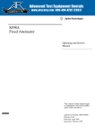
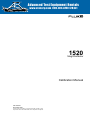
®
E stablished 1981
Advanced Test Equipment Rentals
www.atecorp.com 800-404-ATEC (2832)
®
1520
MegOhmMeter
Calibration Manual
PN 1592594
November 2000
© 2000 Fluke Corporation, All rights reserved. Printed in USA
All product names are trademarks of their respective companies.
Limited Warranty & Limitation of Liability
Each Fluke product is warranted to be free from defects in material and workmanship under normal use and service. The
warranty period is three years and begins on the date of shipment. Parts, product repairs and services are warranted for
90 days. This warranty extends only to the original buyer or end-user customer of a Fluke authorized reseller, and does
not apply to fuses, disposable batteries or to any product which, in Fluke’s opinion, has been misused, altered, neglected,
contaminated, or damaged by accident or abnormal conditions of operation or handling. Fluke warrants that software will
operate substantially in accordance with its functional specifications for 90 days and that it has been properly recorded on
non-defective media.
Fluke authorized resellers shall extend this warranty on new and unused products to end-user customers only but have no
authority to extend a greater or different warranty on behalf of Fluke. Warranty support is available if product is purchased
through a Fluke authorized sales outlet or Buyer has paid the applicable international price. Fluke reserves the right to
invoice Buyer for importation costs of repair/replacement parts when product purchased in one country is submitted for
repair in another country.
Fluke’s warranty obligation is limited, at Fluke’s option, to refund of the purchase price, free of charge repair, or
replacement of a defective product which is returned to a Fluke authorized service center within the warranty period.To
obtain warranty service, contact your nearest Fluke authorized service center to obtain return authorization information,
then send the product to that service center, with a description of the difficulty, postage and insurance prepaid (FOB
Destination), to the nearest Fluke authorized service center. Fluke assumes no risk for damage in transit. Following
warranty repair, the product will be returned to Buyer, transportation prepaid (FOB Destination). If Fluke determines that
the failure was caused by neglect, misuse, contamination, alteration, accident or abnormal condition of operation or
handling, including overvoltage failures caused by use outside of the product’s specified rating, or normal wear and tear of
mechanical components, Fluke will provide an estimate of repair costs and obtain authorization before commencing the
work. Following repair, the product will be returned to the Buyer transportation prepaid and the Buyer will be billed for the
repair and return transportation charges (FOB Shipping Point).
THIS WARRANTY IS BUYER'S SOLE AND EXCLUSIVE REMEDY AND IS IN LIEU OF ALL OTHER WARRANTIES,
EXPRESS OR IMPLIED, INCLUDING BUT NOT LIMITED TO ANY IMPLIED WARRANTY OF MERCHANTABILITY OR
FITNESS FOR A PARTICULAR PURPOSE. FLUKE SHALL NOT BE LIABLE FOR ANY SPECIAL, INDIRECT,
INCIDENTAL OR CONSEQUENTIAL DAMAGES OR LOSSES, INCLUDING LOSS OF DATA, ARISING FROM ANY
CAUSE OR THEORY.
Since some countries or states do not allow limitation of the term of an implied warranty, or exclusion or limitation of
incidental or consequential damages, the limitations and exclusions of this warranty may not apply to every buyer. If any
provision of this Warranty is held invalid or unenforceable by a court or other decision-maker of competent jurisdiction,
such holding will not affect the validity or enforceability of any other provision.
11/99
Fluke Corporation
Fluke Europe B.V.
P.O. Box 9090
P.O. Box 1186
Everett, WA 98206-9090
5602 BD Eindhoven
U.S.A.
The Netherlands
Table of Contents
Title
Page
Introduction........................................................................................................
Contacting Fluke................................................................................................
Precautions and Safety Information...................................................................
International Symbols....................................................................................
Specifications.....................................................................................................
Required Equipment ..........................................................................................
Performance Test ...............................................................................................
Display Test...................................................................................................
Backlight Test................................................................................................
Battery Test ...................................................................................................
Discharge Circuit Test ...................................................................................
Volts and Ohms Measurement Accuracy Verification..................................
LO Ohms Measurement Accuracy Verification ............................................
Meg Ohm Measurement Accuracy Verification............................................
Meg Ohm Voltage Source Accuracy Verification.........................................
Maintaining the Meter........................................................................................
Cleaning.........................................................................................................
Replacing and Disposing of the Batteries......................................................
Testing and Replacing the Fuse.....................................................................
Replacement Parts and Optional Accessories....................................................
i
1
2
2
2
4
6
7
7
8
8
8
8
9
9
11
12
12
12
13
15
1520
Calibration Manual
ii
List of Tables
Table
1.
2.
3.
4.
5.
6.
7.
Title
International Symbols ............................................................................................
Required Equipment...............................................................................................
Display Icons..........................................................................................................
Volts and Ohms Test ..............................................................................................
Lo Ohms Test .........................................................................................................
Meg Ohm Test........................................................................................................
Meg Ohm Voltage Source Test ..............................................................................
iii
Page
2
6
7
8
9
10
11
1520
Calibration Manual
iv
List of Figures
Figure
1.
2.
3.
Title
Page
Display ................................................................................................................... 7
Replacing the Batteries........................................................................................... 13
Replacing the Fuse ................................................................................................. 14
v
1520
Calibration Manual
vi
Introduction
W Warning
To avoid shock or injury, do not perform the verification tests
or calibration procedures described in this manual unless you
are qualified to do so.
The information provided in this document is for the use of
qualified personnel only.
Caution
The 1520 MegOhmMeter contains parts that can be damaged by
static discharge.
Follow the standard practices for handling static sensitive
devices.
The information in this manual deals with the Fluke 1520 MegOhmMeter, (hereafter
referred to as “the Meter”). Information provided includes:
•
•
•
•
•
Precautions and safety information
Specifications
Basic maintenance (cleaning, replacing the battery and fuses)
Performance test procedures
Accessories and replaceable parts
For complete operating instructions, refer to the 1520 Users Manual PN 1543203.
1
1520
Calibration Manual
Contacting Fluke
To order accessories, receive assistance, or locate the nearest Fluke distributor or Service
Center, call:
USA: 1-888-99-FLUKE (1-888-993-5853)
Canada: 1-800-36-FLUKE (1-800-363-5853)
Europe: +31 402-678-200
Japan: +81-3-3434-0181
Singapore: +65-738-5655
Anywhere in the world: +1-425-446-5500
Address correspondence to:
Fluke Corporation
P.O. Box 9090,
Everett, WA 98206-9090
USA
Fluke Europe B.V.
P.O. Box 1186,
5602 BD Eindhoven
The Netherlands
Visit us on the World Wide Web at: www.fluke.com
Precautions and Safety Information
WWarning
If this product is used in a manner not specified by the
manufacturer, the protection provided by the equipment may be
impaired.
Read the “Safety Information” page before servicing this product.
In this manual, a Warning identifies conditions and actions that pose hazard(s) to the
user; a Caution identifies conditions and actions that may damage the Meter or the test
instruments.
International Symbols
International symbols used on the Meter and in this manual are explained in Table 1.
Table 1. International Symbols
Risk of electric shock
See manual
Equipment protected by double or reinforced
insulation
J
Earth
I
Fuse
D
Battery
CAT
III
2
AC or DC
Recycling information
Conforms to CSA C22.2 No 1010.1-92 + Amendment
2 1997, UL 3111 and ANSI/ISA SP82.01 1994
VDE
Conforms to VDE EN61010
(Pending)
Conforms to EU directives
t
Conforms to UL 3111.1
OVERVOLTAGE (Installation) CATEGORY III, Pollution Degree 2 per IEC1010-1 refers to the level of
Impulse Withstand Voltage protection provided. Equipment of OVERVOLTAGE CATEGORY III is equipment
in fixed installations (e.g., electricity meter and primary over-current protection equipment.
MegOhmMeter
Precautions and Safety Information
W Safety Information
Use of instrument in a manner not specified by the
manufacturer may impair safety features/protection provided by
the equipment.
Read the following safety information carefully before using or
servicing the instrument.
To avoid electric shock or fire, do the following:
•
Avoid working alone.
•
Inspect the test leads for damaged insulation or exposed
metal. Check test lead continuity. Damaged leads must be
replaced. Do not use the Meter if it looks damaged.
•
Be careful when working above 30 V ac rms, 42 V ac peak
and 60 V dc. Such voltages pose a shock hazard.
•
When using the probes, keep your fingers away from probe
contacts. Keep your fingers behind the finger guards on the
probes.
•
Measurements can be adversely affected by impedances of
additional operating circuits connected in parallel or by
transient currents.
•
Verify operation prior to measuring hazardous voltages
(voltages above 30 V ac rms, 42 V ac peak and 60 V dc).
•
Place test leads in proper input terminals.
•
Disconnect the live test lead before disconnecting the
neutral test lead.
•
Do not use the Meter if the battery indicator (G ) shows a
battery empty condition.
•
Use only Fluke recommended batteries and fuse.
•
Do not use the Meter with any parts or cover removed.
•
Do not use the Meter around explosive gas, vapor or dust.
•
Disconnect the test leads from power sources and from the
Meter before changing the batteries or fuse.
•
Do not use the Meter in a wet environment.
•
Use only Fluke specified test leads.
3
1520
Calibration Manual
Specifications
Environmental
Operating Temperature
-10 °C to +50 °C
Storage Temperature
-40 °C to +70 °C
Temperature Coefficient
0.10 x (specified accuracy)/ °C
(< 18 °C or > 28 °C)
Relative Humidity:
Non condensing (< 10 °C)
90 % RH (10 °C to 30 °C)
75 % RH (30 °C to 40 °C)
45 % RH (40 °C to 50 °C)(Without Condensation)
Dust/water resistance
IP42 per IEC 529
Operating Altitude
2000 m
Storage Altitude
12000 m
Mechanical Specifications
Size
23,4 x 10 x 6,4 cm
(9.2 x 3.9 x 2.5 in)
Weight
1 kg (2.2 lbs.)
Drop requirement
Per IEC 1010-1
Shock and Vibration
Conforms to MIL-PREF-28800F class 3 & 4
Safety Specifications
Electrical Safety
Meets all requirements of EN61010-1, 1995 and
EN61557, 1997
Maximum Operating Voltage
600 V ac or dc between any terminal and earth
ground
Protection Levels
CAT ,,,, 600 V, Pollution Degree 2 per EN61010-1
Electromagnetic Compatibility (EMC)
Immunity & Emmissions
EN 61326-1
(Unspecified for Field strength in excess of 2V/m)
ESD
EN61000-4-2 Satisfies Criteria B
Electrical Specifications
4
Battery
C Size 1.5 V alkaline, ANSI/NEDA-14A, IEC-LR14
(4 pieces)
Fuse
6 mm x 32 mm (0.25 x 1.25 inch), 0.5 A 660 V, Fast
Acting, 50 A Minimum Interrupt rating
MegOhmMeter
Specifications
Insulation Resistance
Display Ranges
4.000 MΩ, 40.00 MΩ, 400.0 MΩ, 4000 MΩ
Measurement Range (per EN61557-2)
0.250 MΩ to 4000 MΩ
Resolution
0.001 MΩ to 10 MΩ
Accuracy
2 % + 2 counts
0.250 MΩ to 100.0 MΩ
10 % + 2 counts + 1 %/1000 MΩ
100.0 MΩ to 4000 MΩ
Analog Bar Graph
0 to ∞
Test Voltages
250 V, 500 V, 1000 V
Accuracy
+20 %, -0 %
Nominal Current
1 mA
Number of measurements
5,000
Circuitry Protection
test inhibited if ≥ 30 V ac or dc at inputs
Lo Ω
Display Range
40.00 Ω
Measurement Range
0.10 Ω to 40.00 Ω
Accuracy
2 % + 2 counts
Resolution
0.01 Ω
Analog Bar Graph
0 to 100 Ω
Open Circuit Voltage
6 V typical
Short Circuit Current
200 mA minimum, (0.2 to 2.0 Ω for >20% battery
capacity remaining).
Test Leads Zero
2Ω
Number of measurements
5,000
Circuitry Protection
test inhibited if • 30 V ac or dc at inputs
Voltage
Range
600 V, dc, 50/60 Hz
Resolution
1V
Accuracy
2 % + 2 counts
Analog Bar Graph
0 to 1000 V
Resistance
Range
4000 Ω
Accuracy
2 % + 2 counts
Resolution
1Ω
Analog Bar Graph
0 to 10 kΩ
Beeper
On at ≈30 Ω or less
5
1520
Calibration Manual
Required Equipment
Required equipment is listed in Table 2. If the recommended models are not available,
equipment with equivalent specifications may be used.
Repairs or servicing should be performed only by qualified personnel.
Caution
Do not attempt to use the 5500A or other standard calibrator for insulation and
continuity resistance tests. Calibrator damage will result.
Table 2. Required Equipment
Equipment
Calibrator
Minimum Required Characteristics
AC Voltage Range: 0-600 Vac
Accuracy: + 0.5 %
Frequency Range: DC – 60 Hz
Accuracy: +3 %
Recommended Model
9100 w/135 option
DC Voltage Range: 0-600 Vdc
Accuracy: + 0.5 %
Ohms Range: 0 Ω - 4000Ω
Accuracy: + 0.5 %
Insulation Resistance: 250 kΩ, 500 kΩ, 1 MΩ,
80 MΩ
Accuracy: + 0.5%
Continuity Resistance: 2 Ohms, 20 Ohms
Accuracy: + 0.5%
HV Divider
DC Voltage Range: 1 kV – 5 kV
Fluke 80K-40
Accuracy: + 1%
Division Ratio: 1000:1
Input resistance: 1000 MΩ
DMM
6
DC Voltage Range: 1 – 1000 Vdc
Accuracy: + 0.25%
Fluke 87-3
MegOhmMeter
Performance Test
Performance Test
WWarning
While performing the following procedures, there are potentially
dangerous voltages at the Meter output terminals when the
Meter is in the MΩ function.
The following performance tests will ensure that the meter is in proper operating
condition and meets the published accuracy specifications. If the Meter fails any of the
performance test steps, repair is needed.
To perform the tests you will need equipment meeting the minimum specification given
in Table 2.
Display Test
While turning the Meter on, push and hold down the beeper button. Compare the display
with the example in Figure 1. Check all segments for clarity and contrast.
1
2
3
4
10
5
9
8
7
6
acf12f.eps
Figure 1. Display
Table 3. Display Icons
A
Voltage applied to the probes in Insulation Resistance function.
B
Low Resistance/Resistance function indicator.
C
Resistance reading held from the last measurement in Insulation Resistance or Low Resistance
function.
D
Beeper symbol shows if beeper function is turned on in Resistance function.
E
Zero symbol is on if test leads are zeroed out.
F
Main reading display for all functions.
G
Analog bar graph displays resistance on a logarithmic scale and voltage on a linear scale. The
value always tracks the main reading.
H
High voltage warning symbol flashes if voltage ≥ 30 V ac or dc is present on the probes.
I
Battery life indicator. Displays briefly when the Meter is first switched to a function. Displays the
amount of battery voltage left in increments of 25 %.
J
Lock symbol is on if the TEST mode is locked in Insulation or Low Resistance functions.
7
1520
Calibration Manual
Backlight Test
Push the backlight button and note that the all three backlight LEDs come on. Each LED
can be seen on the left side of the display as an intensified area.
Battery Test
Turn the Rotary Switch to the Battery Check position and note that the batteries have
90% or better charge. Replace if necessary. Refer to "User Maintenance" for detailed
instructions on changing the batteries.
Discharge Circuit Test
The following Discharge Circuit Test is a safety related test that verifies input jack wiring
to the PCA, the RSOB contacts, RSOB pads on the PCA, and other active components on
the PCA.
Caution
DO NOT push the Meter TEST button during the following
procedure.
1. Connect the DMM to the VΩ and COM jack of the Meter.
2. Set the DMM to kΩ function.
3. Turn the Meter Rotary Switch to the 250V, 500V, 1000V and Lo Ω position. Check
that the DMM reading for each position is between 1600 and 2600 Ω.
Volts and Ohms Measurement Accuracy Verification
To verify accuracy of the V and Ω function, complete the following:
Perform the battery test and replace as necessary
1. Connect the Calibrator to the VΩ and COM inputs on the Meter.
2. Turn the Meter Rotary Switch to the function listed for each step of Table 4.
3. Apply the input for the steps 1 through 10 as listed in Table 4.
4. Compare the Meter displayed reading with the display limits of Table 4.
5. DISCONNECT THE CALIBRATOR FROM THE METER.
Table 4. Volts and Ohms Test
Display Reading
Step
8
Function
Source Output
Lower Limit
Upper Limit
1
Volts
0 Volts
-2
2
2
Volts
180 V
174
186
3
Volts
540 V
527
553
4
Volts
180 V @ 60 Hz
174
186
5
Volts
540 V @ 60 Hz
527
553
6
Ω
0Ω
0
2
7
Ω
1200 Ω (UTTi High)
1174
1226
8
Ω
3600 Ω (UUTi High)
3526
3674
9
Ω
Open
>4000
>4000
10
Continuity on
27 Ω
Beeper on
Beeper on
MegOhmMeter
Performance Test
LO Ohms Measurement Accuracy Verification
Caution
During the following tests, the 9100 source output must be
applied to the UUT prior to pushing the UUT TEST button.
Failure to do this WILL damage the 9100.
Do not attempt to use the 5500A or other standard calibrator for
the following test. Calibrator Damage will result.
Use the calibrator continuity resistance function to verify accuracy of the LO Ω function
as follows:
1. Turn the Meter Rotary Switch to LO Ω.
2. Connect the calibrator to the Meter VΩ and COM input terminals using 4 wire test
leads.
3. Apply zero ohms from the calibrator.
4. Zero the LO ohms function (press and release the TEST button and then press and
hold the ZERO button until the Meter beeps).
5. Apply the Calibrator Output values listed in Table 5 and compare the Meter reading
with the display reading limits given.
Table 5. Lo Ohms Test
Display Reading Limits
Step
Function
Calibrator Output
Lower Limit
Upper Limit
1
LO Ohms
2 Ohms
1.94
2.06
2
LO Ohms
20 Ohms
19.58
20.42
Meg Ohm Measurement Accuracy Verification
Use the calibrator Insulation Resistance function to verify MΩ measurement accuracy as
follows:
Caution
During the following tests the 9100 source output must be
applied to the UUT prior to pushing the UUT TEST button.
Failure to do this WILL damage the 9100.
Do not attempt to use the 5500A or other standard calibrator for
the following test. Calibrator Damage will result.
9
1520
Calibration Manual
WWarning
Pushing the TEST button produces a potentially dangerous
voltage, at the Meter output terminals, when the Meter is in the
MΩ function.
1. Turn the Meter Rotary Switch to the MΩ function and set the Meter range as listed in
Table 6.
2. Apply the calibrator output values listed in step 1 of Table 6.
3. Press and hold the Meter TEST button until the Meter display reading settles to its
final value.
4. Compare the Meter displayed reading with the display reading limits of Table 6.
5. Release the TEST button.
6. Repeat the above process for all remaining steps in Table 6.
Table 6. Meg Ohm Test
Display Reading
Step
10
Function
Range
Calibrator Output
Lower Limit
Upper Limit
1
MΩ
250 V
250 kΩ
243
257
2
MΩ
500 V
250 kΩ
243
257
3
MΩ
1000 V
250 kΩ
243
257
4
MΩ
250 V
500 kΩ
488
512
5
MΩ
500 V
500 kΩ
488
512
6
MΩ
1000 V
500 kΩ
488
512
7
MΩ
250 V
1 MΩ
0.978
1.022
8
MΩ
500 V
1 MΩ
0.978
1.022
9
MΩ
1000 V
1 MΩ
0.978
1.022
10
MΩ
250 V
80 MΩ
78.2
81.8
11
MΩ
500 V
80 MΩ
78.2
81.8
12
MΩ
1000 V
80 MΩ
78.2
81.8
13
MΩ
250 V
Open
>1000
>1000
14
MΩ
500 V
Open
>2000
>2000
15
MΩ
1000 V
Open
>4000
>4000
MegOhmMeter
Performance Test
Meg Ohm Voltage Source Accuracy Verification
To verify MΩ Voltage Source Accuracy complete the following procedure:
WWarning
Pushing the TEST button produces a potentially dangerous
voltage, at the Meter output terminals, when the Meter is in the
MΩ function.
1. Connect the DMM, listed in Table 2, to the Meter VΩ and COM input terminals. Set
the DMM to the VDC function.
2. Turn the Meter Rotary Switch to the MΩ function and range listed in Table 7, step 1.
3. Press and hold the TEST button until the Meter reading settles to its final value.
4. Compare the DMM reading with the display reading limits of Table 7.
5. Release the TEST button.
6. Repeat the above process for Table 7, Step 2.
7. Disconnect the DMM from the Meter and connect the HV Divider to the DMM.
8. Connect the DMM, with HV Divider, to the Meter VΩ and COM input terminals.
9. Press and hold the TEST button until the Meter reading settles to its final value.
10. Compare the DMM display reading with the display reading limits of Table 7,
step 3.
Table 7. Meg Ohm Voltage Source Test
Display Reading
Step
Function
Range
Measurement Device
Lower Limit
Upper Limit
1
MΩ
250 V
Test DMM
250
300
2
MΩ
500 V
Test DMM
500
600
3
MΩ
1000 V
Test DMM with HV Divider
1.000
1.200
11
1520
Calibration Manual
Maintaining the Meter
This section provides basic maintenance information, including fuse and battery
replacement instructions.
Caution
Do not attempt to repair or service your Meter unless you are
qualified to do so and have the relevant calibration,
performance test, and service information.
Cleaning
Clean only with soap and water. Remove any residue afterwards.
Periodically wipe the case with a damp cloth and mild detergent.
Do not use abrasives or solvents.
Replacing and Disposing of the Batteries
W Warning
To avoid electric shock, disconnect the test leads from the
inputs before opening the Meter for battery replacement.
To avoid false readings, which could lead to possible electric
shock or personal injury, replace the batteries as soon as the
battery empty indicator G appears.
Note
This Meter contains alkaline batteries. Do not dispose of these batteries
with other solid waste. Used batteries should be disposed of by a qualified
recycler or hazardous materials handler. Contact your authorized Fluke
Service center for recycling information.
The Meter uses four alkaline C cell batteries (supplied). To replace the batteries, do the
following (see Figure 2):
1. Turn the rotary switch to the OFF position.
2. Disconnect test leads from any power source.
3. Remove the holster.
4. Place the Meter face down on a nonabrasive surface and loosen the two screws with a
flat-blade screwdriver.
5. Lift the battery access lid away from the Meter.
6. Replace the C cells as shown in Figure 2. Observe the battery polarity shown in the
battery compartment.
7. Secure the battery access lid back in position with the two screws.
12
MegOhmMeter
Maintaining the Meter
acf10f.eps
Figure 2. Replacing the Batteries
Testing and Replacing the Fuse
W Warning
To avoid electric shock, disconnect the test leads from the
inputs before opening the Meter for fuse replacement.
To prevent personal injury or damage to the Meter, install ONLY
the Fluke specified fuse identified in the “Replacement Parts
and Optional Accessories” section.
Before replacing the fuse, test it as described in the next section.
Testing the Fuse
Use the following procedure to test the internal fuse of the Meter.
1. Turn the rotary switch to the Lo Ω Function.
2. Connect the test leads to the input terminals and short them together. Press TEST.
3. The display should indicate approximately 0.5 Ω. If the display reads >40 Ω, replace
the fuse as described next and test again.
13
1520
Calibration Manual
Replacing the Fuse
W Warning
To avoid electric shock, personal injury or damage to the Meter,
use ONLY the specified fuse, and in accordance with the
following procedure.
If the previous fuse test indicates that the fuse is defective (resistance > 40 Ω), replace the
fuse as follows:
1. Turn the rotary switch to the OFF position.
2. Disconnect test leads from any power source.
3. Follow Steps 3 - 5 to remove the battery access lid as described under "Replacing and
Disposing of the Batteries".
4. Unscrew the bottom cover as shown in Figure 3.
5. Remove the fuse as shown in Figure 3.
6. Replace with a new fuse.
7. Place the bottom cover on and secure the screws.
8. Insert the batteries. Observe the battery polarity shown in the battery compartment.
9. Secure the battery access lid.
10. Test the fuse as described under "Testing the Fuse".
acf11f.eps
Figure 3. Replacing the Fuse
14
MegOhmMeter
Replacement Parts and Optional Accessories
Replacement Parts and Optional Accessories
Replacement Part
Part Number
Battery 1.5 V Alkaline Size C
423582
Test Lead set
669058
Test Probe, 1 kV, lantern tip, red
803459
Test Probe, 1 kV, lantern tip, black
803467
Alligator Clip, red
803434
Alligator Clip, black
803442
Carrying Case
603115
Holster
670643
Hand Strap
669069
Fuse,0.5A,750VAC,Fast Acting,0.25X1.25,Glass Tube
1556096
Battery Spring
936906
Screw
942946
Shock Absorber
948708
Battery Cover (Overmolded)
1274679
Hook, (Pad Transfer)
1270801
User Manual, Multi-Language
1543203
CD Rom (containing Fluke Users Manual)
1558934
Optional Accessories
Part Number
Harness
669074
Tool Pack
669903
15
1520
Calibration Manual
16