1
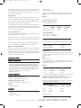
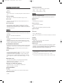
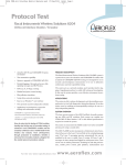
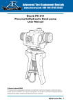
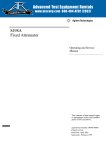
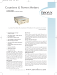
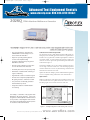
2026qiss8.qxd
01/Dec/2004
14:19
®
Page 1
Advanced Test Equipment Rentals
Signal
Sources
www.atecorp.com 800-404-ATEC (2832)
E stablished 1981
2026Q CDMA Interferer Multisource Generator
The 2026Q is designed to work with a radio test set to provide a fully integrated radio receiver test
solution for cellular and PCS systems
•
Two tone interference generation for
AMPS/CDMA receiver testing in accordance with IS-97-A/IS-98-A
•
Option for providing GSM signals for
receiver and amplifier testing
•
Combiner output frequency range from
800 MHz to 2.0 GHz
•
Provides single calibrated point of reference for the transceiver under test
•
Excellent phase noise and spectral purity
•
Elimination of additional RF combining or
signal conditioning
•
High internal isolation of returned signals
•
Includes two independent, fully featured
RF signal generators 10 kHz to 2.4 GHz
•
Very low levels of internally generated
intermodulation products
•
Single unit solution for CDMA interference testing
Calibrated and Combined Signal Path
It is designed to produce a fully calibrated combined RF output containing any mix of internally generated interference signals from its
two RF sources, together with a calibrated signal path for a radio test
set transmit output. A return path from the transceiver back to the
radio test set receiver input is also provided through the instrument
as illustrated in figure 1.
This allows a CDMA receiver to be tested for sensitivity in the presence of single or dual tone interference. The interfering signals are
combined without the need for any RF switching mechanism that
would otherwise affect the test result.
Option 116 allows the 2026Q to provide GSM modulated signals for
receiver or amplifier testing with low floor noise characteristics.
High Isolation
2026Q is configured to ensure high levels of isolation between each
of the transmit and receive paths between the radio test set, the
interfering signal sources and the transceiver under test.
The 2026Q is a derivative of the popular 2026
MultiSource RF signal generator. It has been
designed to work directly with a CDMA radio test
set to produce a fully integrated radio receiver
test solution for CDMA cellular and PCS systems
in accordance with IS-97-A/IS-98-A.
Figure 1 : 2026Q configured for radio testing with a test set
For the very latest specifications visit
www.aeroflex.com
2026qiss8.qxd
01/Dec/2004
14:19
Page 2
Path loss test data is supplied with each instrument for the frequency bands 865 MHz - 895 MHz, 1750 MHz - 1990 MHz. Drift influences within these bands is minimal ensuring a level accuracy of better than ±0.75 dB. The frequency response across each of these
bands is flat to within ±0.1 dB, thus minimizing the need for additional system calibration.
Independent Signal Generators
Each of the RF generators contained within 2026Q may be used independently, routed to their individual RF connectors. In this mode,
each generator covers the full frequency range 10 kHz to
2.4 GHz with an output power of between -137 dBm and +24 dBm.
Each source may be independently modulated either from an internal
or external source(s). Modulation modes include AM, FM, PM,
Pulse and 2/4 level FSK. The standard 2026 specification applies
when used in this mode.
The flexibility of the signal routing allows the 2026Q to accept an
external input from another signal generator, such as the 2050 Digital
and Vector Generator producing CDMA modulation or a radio test
set.
Excellent Spectral Purity
Automatic Source Coupling
Very low phase noise and spurious responses are achieved making
them ideal for CDMA handset interference tests and other general
purpose applications. The 2026Q has a low residual FM of typically
3 Hz and typical sideband noise of -121 dBc/Hz at 20 kHz offset from
1 GHz.
The two internal generators can have their frequency and level ‘coupled’. In the case of RF level this coupling can be any fixed offset
enabling control of a single parameter to manifest a change in both
sources. For RF frequency this coupling can be both a fixed frequency offset or a harmonically related offset and again allow simple programming and control of the instrument.
The excellent noise floor performance is more than adequate for
mobile handset and base station testing.
Setting up the source and combiner routing
Setting up coupling
Sweep
Typical SSB Phase Noise at 1 GHz
The 2026Q allows either of the independent RF sources to be frequency swept with user defined start, stop, and step values to reduce
the amount of operator time or GPIB overhead. By enabling the coupling facility, sweeping one source will simultaneously sweep the
other internal RF source to allow automated swept measurements on
frequency conversion devices to be made.
High RF Output
Each of the RF signal generators is able to deliver up to +24 dBm at
their output, making them ideal for testing components such as mixers and amplifiers etc.
Comprehensive Modulation
Typical Phase Noise at 20 kHz offset
Flexible Source Routing
Each of the signal sources can either be routed to a separate output
connector or switched to the input of an RF combiner network before
being fed to the combiner output connector. The combiner routing
is set up quickly and effectively using the Combiner Set Up menu.
Each signal source is capable of being independently modulated from
its own fully programmable modulation source to ensure maximum
flexibility. The internal modulation sources are each capable of generating sine, triangle or square wave signals.
Amplitude, frequency and phase modulated carriers can be generated from the internal modulation sources or from the independent
external inputs.
2026qiss8.qxd
01/Dec/2004
14:19
Page 3
The frequency modulation system provides excellent performance in
the DC coupled mode with very low carrier frequency error and stability ensuring that the generator can accurately test receivers sensitive to small frequency errors.
Programming
A GPIB interface is fitted so that all standard signal generator functions are controllable over the bus. The protocol and syntax of GPIB
commands has been designed in accordance with IEEE 488.2 standard to facilitate the generation of ATE programs.
A RS-232 interface is fitted as standard with a common command set
to GPIB commands. RS-232 control is particularly suitable for use
with simple external controllers or RF modems when the instrument
is being used in a remote location.
Combiner outputs
-137 dBm to -3 dBm(1)
Maximum output is reduced by 5 dB when pulse modulation is selected and/or by up to 6 dB when AM is selected dependent upon AM
depth.
Resolution
0.1 dB or 3 digits for linear units
Accuracy (Individual RF outputs)
(over temp range 17 to 27°C)
RF Level
-127 dBm to -100 dBm to
+6 dBm(2)
-100 dBm
Up to 1.2 GHz ±1.0 dB
Above 1.2 GHz ±1.6 dB
±0.8 dB
±1.6 dB
>+6 dBm
to +24 dBm
±1.0 dB
±2.0 dB
Low Cost of Ownership
An electronic trip protects the individual source outputs against the
accidental application of reverse power.
Careful attention to the thermal design and the use of well-proven
signal generator modules gives high reliability and calibration validity.
The use of flash memory and software download via the RS-232 interface means the 2026Q can be upgraded with its covers fitted.
Option 116 - GSM Modulation
Option 116 is avaialble to allow 2026A/B to emulate GSM signals
using FM techniques which achieves superior noise floor performance than solutions using IQ systems. The facility is ideal for testing
GSM receiver selectivity and for testing the linearity of high performance multi-carrier power amplifiers.
GENERAL DESCRIPTION
The 2026Q CDMA Interferer MultiSource Generator is a purpose built
instrument for testing CDMA hand-set and base station equipment. It
features two synthesized RF signal generators with both independent
and combined RF outputs. The combined RF output provides a path
to and from the radio under test and an appropriate CDMA radio test
set. Each signal source covers the frequency range 10 kHz to 2.4
GHz, whilst the combined path covers the range
800 MHz to 2.0 GHz.
Independent source frequency range
10 kHz to 2.4 GHz with a resolution of 1 Hz
Combined output frequency range
800 MHz to 2.0 GHz with a resolution of 1 Hz
Accuracy
Accuracy (Combined RF output)
(over temp range 17 to 27°C and level range -20 dBm to -35 dBm)
RF Frequency range
865 MHz - 895 MHz
1750 MHz - 1990 MHz
Level Accuracy
±0.75 dB
±0.75 dB
Attenuator hold
Inhibits operation of the step attenuator from the level at which the key
is enabled. Useable for a level reduction of at least 10 dB. Typical
accuracy ±3 dB.
VSWR
SPECIFICATION
CARRIER FREQUENCY
Temperature Stability
Up to 1.2 GHz <±0.02 dB/°C
Above 1.2 GHz <±0.04 dB/°C
Individual outputs
For output levels less than -5 dBm, output VSWR is less than 1.5:1 for
carrier frequencies up to 1.2 GHz and less than 1.7:1 for carrier frequencies up to 2.4 GHz.
Path Loss
865 MHz to 895 MHz 1750 MHz to 1990 MHz
( X → Y)*
( Y → Z)
( Y → X)
14 dB typ.
13.5 dB typ.
>40 dB
15 dB typ.
13.5 dB typ.
> 40 dB
* -measured values are supplied with each instrument with a frequency
response of <± 0.1 dB across the frequency bands
865 MHz to 895 MHz, 1750 MHz to 1780 MHz and 1930 MHz to
1990 MHz. Measurement uncertainty of ± 0.25 dB applies.
Options are available providing lower path loss figures - please contact
your IFR sales office for further details.
VSWR (refer to Figure 1)
As frequency standard
Port X
Port Y
Port Z
RF OUTPUT
Range
Individual outputs
-137 dBm to +24 dBm(1)
For the very latest specifications visit
865 MHz to 895 MHz
1750 MHz to 1990 MHz
<1.2:1
<1.6:1*
<1.35:1
<1.35:1
<1.6:1*
<1.35:1
*Typically <1.25:1
www.aeroflex.com
2026qiss8.qxd
01/Dec/2004
14:19
Page 4
sources.
Maximum
Port X
Port Y
Port Z
Safe Power (matched)
+19 dBm
+33 dBm
+33 dBm
RF Output connector
50 Ω type N connector to MIL-PRF-39102.
Output protection
Individual outputs
Protected from a source of reverse power up to 50 W from 50 Ω or 25
W from a source VSWR of 5:1. Protection circuit can be reset from
the front panel or via the GPIB interface.
Combined output
No reverse power protection.
SPECTRAL PURITY
Harmonics
Individual outputs:
Typically better than -30 dBc for RF level up to +6 dBm, typically better than -25 dBc for RF levels up to +18 dBm (+14 dBm above 1.2
GHz).
Combined output:
Typically better than -30 dBc for RF level up to -36 dBm, typically better than -25 dBc for RF levels up to -13 dBm.
Non-Harmonics
Better than -70 dBc to 1 GHz, better than -64 dBc above 1 GHz, better than -60 dBc above 2 GHz.
Isolation
Better than 80 dB between individual outputs in use.
Better than 60 dB from a used individual output and the combiner
output.
Intermodulation
<-80 dBc at an RF output level of -22 dBm on the combiner, across
the range 800 MHz to 2.0 GHz. Intermodulation levels reduce with
reducing RF Level.
Residual FM (FM off)
Less then 4.5 Hz RMS deviation in a 300 Hz to 3.4 kHz un-weighted
bandwidth at 1 GHz. Typically <1 Hz at 249 MHz, <3 Hz at
1001 MHz.
Radio Connections
Refer to Figure 1
SSB phase noise
Better than -124 dBc/Hz at 20 kHz offset from a carrier frequency of
470 MHz, typically -121 dBc/Hz at 20 kHz offset from a carrier frequency of 1 GHz.
Carrier Leakage
Less than 0.5 µV PD at the carrier frequency in a two turn 25 mm
diameter loop, 25 mm from the surface of the signal generator.
The internal modulation sources are capable of generating two simultaneous signals into any one of the modulation channels. Each internal
and external modulation source can be simultaneously enabled to produce combined amplitude and frequency (or phase) modulation.
Pulse modulation can be applied to each of the carriers from external
pulse sources. The pulse modulation can be used in combination with
the other forms of modulation.
2 level or 4 level FSK modulation can be applied to each carrier using
data from an external source.
FREQUENCY MODULATION
Deviation
0 to 100 kHz
Resolution
3 digits or 1 Hz
Accuracy at 1 kHz
±5%
Bandwidth (1 dB)
DC to 100 kHz (DC coupled)
10 Hz to 100 kHz (AC coupled)
20 Hz to 100 kHz (AC coupled with ALC)
Group delay
Less then 5 µs to 100 kHz
Carrier frequency offset (DC coupled)
Less than 1% of the set frequency deviation
Distortion
Less than 1% at 1 kHz rate for deviations up to 100 kHz
Typically ≤0.3% at 1 kHz rate for deviations up to 10 kHz
Less than 3% at 1 kHz rate and deviations upto 100 kHz for carrier
frequencies below 50 MHz
Modulation source
Internal modulation oscillator or external via front panel BNC
FSK
Modes
2 level or 4 level FSK
Data source
External data input via a 25 way rear panel D Type connector
Frequency shift
Variable up to ±100 kHz
Accuracy
As FM deviation accuracy
Timing jitter
±3.2 µs
Filter
MODULATION CAPABILITY
FM, AM or phase modulation can be applied to the carriers generated
by each signal source from independent internal or external modulation
8th order Bessel, -3 dB at 3.9 kHz
2026qiss8.qxd
01/Dec/2004
14:19
Page 5
PHASE MODULATION
ance
Deviation
A logic 0 (0 V to 1 V) turns the carrier off, a logic 1 (3.5 V to 5 V)
turns the carrier on
0 to 10 radians
Maximum input is ±15 V
Resolution
On/off ratio
3 digits or 0.01 radians
Better than 45 dB below 1.2 GHz, better than 40 dB above 1.2 GHz
Accuracy at 1 kHz
Rise and fall times
±5% of indicated deviation excluding residual phase modulation
Less than 10 µs
3 dB Bandwidth
Overshoot
100 Hz to 10 kHz
<1 dB
Distortion
Less than 3% at 10 radians at 1 kHz modulation rate. Typically <0.5%
for deviations up to 1 radian at 1 kHz
Modulation source
Internal LF generator or external via front panel BNC.
MODULATION OSCILLATOR
The internal modulation oscillator for each signal source is capable of
generating one or two modulation tones simultaneously in one modulation channel.
Frequency range
AMPLITUDE MODULATION
0.01 Hz to 20 kHz with a resolution of 0.01 Hz
For carrier frequencies <500 MHz, useable to 1.5 GHz on the individual outputs
Range
Frequency accuracy
As frequency standard
Distortion
0 to 99.9%
Less than 0.1% THD at 1 kHz
Resolution
Waveforms
0.1%
Sine wave to 20 kHz and a triangular or square wave to 3 kHz
Accuracy(3)
Square wave jitter
±5% of set depth at 1 kHz rate
<6.4 µs on any edge
1 dB Bandwidth
Audio Output
DC to 30 kHz (DC coupled)
The modulation oscillator signal from each source is available on the
front panel Modulation Input/Output BNC connector at a nominal level
of 2 V RMS EMF from a 600 Ω source impedance.
10 Hz to 30 kHz (AC coupled)
20 Hz to 30 kHz (AC coupled with ALC)
EXTERNAL MODULATION
Distortion(3)
Input on the front panel Modulation Input/Output connector. The modulation is calibrated with 1.414 V peak (1 V RMS sine wave) applied.
Input impedance is 100 kΩ nominal. Maximum safe input ±15 V.
<1.5% at 1 kHz rate for modulation depths up to 30%
<2.5% at 1 kHz rate for modulation depths up to 80%
Modulation source
MODULATION ALC
Internal LF generator or external, via front panel BNC
The external modulation input can be levelled by a peak levelling ALC
system over the input voltage range of 0.75 V to 1.25 V RMS sine
wave. High and low indicators in the display indicate when the input is
outside levelling range.
PM on AM
Typically 0.1 radians at 30% depth at 470 MHz
PULSE MODULATION
SWEEP MODE
Frequency range
The carrier frequency of one source can be swept. To enable more
than one source to be swept the coupling facility must be invoked.
32 MHz to 2.4 GHz, useable to 10 MHz
Control parameters
RF level range
Maximum guaranteed output is reduced by 5 dB when pulse modulation is selected
Step time
RF level accuracy
50 ms to 10 s per step
When pulse modulation is enabled, adds ±0.5 dB to the RF level
accuracy specification
Trigger
Control
Pulse input is on a front panel BNC with 10 kΩ nominal input imped-
For the very latest specifications visit
Start/stop values of carrier frequency, frequency step size and time per
step.
A trigger input is available on a rear panel BNC connector and can be
used in single, continuous, start/stop or single step mode.
www.aeroflex.com
2026qiss8.qxd
01/Dec/2004
14:19
Page 6
FREQUENCY STANDARD (OCXO)
Frequency
10 MHz
Ageing rate
±2.5 in 107 per year, ±5 in 109 per day after 2 months continuous
use.
Temperature Stability
Better than ±5 in 108 over the temperature range 0 to 50°C.
Warm up time
Within 2 in 107 of final frequency 10 minutes after switch on at a
temperature of 20°C.
External input/output
Rear panel BNC connector accepts an external input of 1 MHz or
10 MHz at a level of 220 mV RMS to 1.8 V RMS into 1 kΩ. Rear
panel BNC connector provides an output of 10 MHz at a nominal level
of 2 V pk-pk into 50 Ω.
DIMENSIONS AND WEIGHT
(over projections but excluding front panel handles)
Height
Width
Depth
Weight
177 mm
419 mm 488 mm <17kg
OPTIONS
OPTION 116 - GSM MODULATION
Option 116 is available on 2026Q and 2026A/B signal generators.
Baseband source
Data rate
270.833333 kHz (13 MHz/48).
Data rate accuracy
As 10 MHz frequency standard.
Filter
Gaussian filter approximated by eight-pole RC network.
Number of outputs
GENERAL
GPIB INTERFACE
All signal source parameters except the supply switch are remotely programmable.
Designed in accordance with IEEE 488.2.
RS-232
All signal source parameters except the supply switch are remotely programmable.
Connector is 9 way D type, baud rate 300 to 9600 bits per second.
Handshake hardware is DTR, RTS, CTS and DSR and software is XON
and XOFF. Electrical interface is to EIA-232-D.
ELECTROMAGNETIC COMPATIBILITY
Conforms with the protection requirements of the EEC Council Directive
89/336/EEC. Conforms with the limits specified in the following standards:
IEC/EN61326-1 : 1997, RF Emission Class B, Immunity Table 1,
Performance Criteria B
SAFETY
Conforms with the requirements of EEC Council Directive 73/72/EEC
and Standard IEC/EN 61010-1 : 1993
Complies with IEC 1010-1, BS EN61010-1 class 1 portable equipment and is for use in a pollution degree 2 environment. The instrument is designed to operate from an installation category 1 or 2 supply.
RATED RANGE OF USE
(Over which full specification is met unless otherwise indicated.)
Temperature 0 to 55°C, Humidity up to 93% at 40°C
Altitude up to 3050 m (10,000 ft)
CONDITIONS OF STORAGE AND TRANSPORT
Temperature -40 to +71°C, Humidity up to 93% at 40°C
Altitude up to 4600 m (15,000 ft)
POWER REQUIREMENTS
AC Supply
90 to 132 V or 188 to 255 V, 47 Hz to 63 Hz, 250 VA maximum
CALIBRATION INTERVAL
2 years
3
Data pattern
(215 -1) PRBS sequence.
The outputs are separated in time to ensure that they are not correlated.
ACCURACY
FM deviation
Typically better than 2% when used as described.
SPECTRAL CHARACTERISTIC
Wideband noise
For an output of +10 dBm on the individual output typically -83 dBc
measured in a 100 kHz bandwidth relative to the modulated signal
measured in a 30 kHz bandwidth at 6 MHz offset, in accordance with
ETSI-defined measurement methods on wideband noise.
(1) Level uncalibrated above +20 dBm for frequencies >1.2 GHz (-7 dBm at
combiner output)
(2) Level accuracy is unspecified below 100 kHz for levels >+6 dBm
(3) For RF output levels not exceeding +10 dBm (-22 dBm at combiner output)
2026qiss8.qxd
01/Dec/2004
14:19
Page 7
VERSIONS AND ACCESSORIES
.
When ordering please quote the full ordering number information.
Ordering Numbers
Versions
2026Q
CDMA Interferer MultiSource Generator
Options
Option 116
GSM PRBS modulation
Supplied with
AC power supply lead
46882/361
Operating Manual
46880/087
Service Manual
Optional Accessories
46884/293
Rack mounting kit, depths from 480 mm to 680 mm
46884/294
Rack mounting kit, depths from 680 mm to 840 mm
46884/931
Rack mounting kit containing front panel brackets only
46662/614
Soft carrying case
43129/189
1.5 m GPIB lead
46884/650
RS-232 Cable 9 way female to a 9 way female 1.5 m
46884/649
RS-232 Cable 9 way female to a 25 way female 1.5 m
For the very latest specifications visit
www.aeroflex.com
2026qiss8.qxd
01/Dec/2004
14:19
Page 8
CHINA Beijing
Tel: [+86] (10) 6467 2761 2716
Fax: [+86] (10) 6467 2821
GERMANY
Tel: [+49] 8131 2926-0
Fax: [+49] 8131 2926-130
SCANDINAVIA
Tel: [+45] 9614 0045
Fax: [+45] 9614 0047
CHINA Shanghai
Tel: [+86] (21) 6282 8001
Fax: [+86] (21) 62828 8002
HONG KONG
Tel: [+852] 2832 7988
Fax: [+852] 2834 5364
SPAIN
Tel: [+34] (91) 640 11 34
Fax: [+34] (91) 640 06 40
FINLAND
Tel: [+358] (9) 2709 5541
Fax: [+358] (9) 804 2441
INDIA
Tel: [+91] 80 5115 4501
Fax: [+91] 80 5115 4502
UK Burnham
Tel: [+44] (0) 1682 604455
Fax: [+44] (0) 1682 662017
FRANCE
Tel: [+33] 1 60 79 96 00
Fax: [+33] 1 60 77 69 22
KOREA
Tel: [+82] (2) 3424 2719
Fax: [+82] (2) 3424 8620
As we are always seeking to improve our products,
the information in this document gives only a general
indication of the product capacity, performance and
suitability, none of which shall form part of any contract. We reserve the right to make design changes
without notice. All trademarks are acknowledged.
Parent company Aeroflex, Inc. ©Aeroflex 2004.
UK Stevenage
Tel: [+44] (0) 1438 742200
Fax: [+44] (0) 1438 727601
Freephone: 0800 282388
USA
Tel: [+1] (316) 522 4981
Fax: [+1] (316) 522 1360
Toll Free: 800 835 2352
w w w.aeroflex.com
[email protected]
Our passion for performance is defined by three
attributes represented by these three icons:
solution-minded, performance-driven and customer-focused.
Part No. 46891/004, Issue 8, 02/04