1
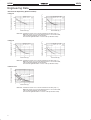
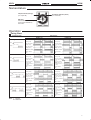
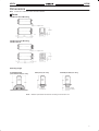
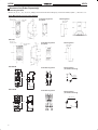
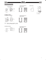
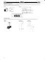
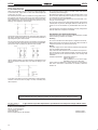
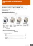
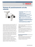
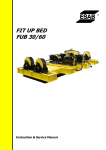
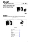
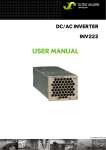
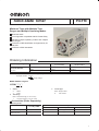
Solid-state Timer
H3YN
Miniature Timer with Multiple Time
Ranges and Multiple Operating Modes
Minimizes stock.
Pin configuration compatible with MY Power Relay.
Standard multiple operating modes and multiple
time ranges.
Conforms to VDE 0435/P2021 and approved by UL
and CSA.
Conforms to EMC standards.
Ordering Information
Supply voltage
Time-limit contact
Short-time range model
(0.1 s to 10 min)
Long-time range model
(0.1 min to 10 h)
24, 100 to 120, 200 to 230 VAC;
12 24,
12,
24 48,
48 100 to 110,
110
125 VDC
DPDT
H3YN-2
H3YN-21
4PDT
H3YN-4
H3YN-41
24 VDC
4PDT (Twin contact)
H3YN-4-Z
H3YN-41-Z
Note:
Specify both the model number and supply voltage when ordering.
Example: H3YN-2 24 VAC
Supply voltage
Model Number Legend:
H3YN-jj-j
1
2
3
1.
Output
2:
DPDT
4:
4PDT
3.
2.
Time Range
None: Short-time range (0.1 s to 10 min)
1:
Long-time range (0.1 min to 10 hrs)
Contact Type
None: Single contact
Z:
Twin contact
Accessories (Order Separately)
Connecting Socket
Timer
Track mounting/Front
g
connecting
ti socket
k t
Back connecting socket
Solder terminal
Wire-wrap terminal
PC terminal
H3YN-2/-21
PYF08A, PYF08A-N
PY08
PY08QN(2)
PY08-02
H3YN-4/-41
H3YN-4-Z/-41-Z
PYF14A, PYF14A-N
PY14
PY14QN(2)
PY14-02
1
H3YN
H3YN
Hold-down Clips
Model
Applicable socket
Y92H-3
PYF08A, PYF08A-N,
PYF14A, PYF14A-N
Y92H-4
PY08, PY08QN(2), PY08-02
PY14, PY14QN(2), PY14-02
Specifications
Ratings
Item
H3YN-2/-4/-4-Z
H3YN-21/-41/-41-Z
Time ranges
0.1 s to 10 min (1 s, 10 s, 1 min, or 10 min
max. selectable)
Rated supply voltage
24, 100 to 120, 200 to 230 VAC; 12, 24, 48, 100 to 110, 125 VDC (see note 1)
Pin type
Plug-in
Operating mode
ON-delay, interval, flicker OFF start, or flicker ON start (selectable with DIP switch)
Operating voltage range
85% to 110% of rated supply voltage (12 VDC: 90% to 110% of rated supply voltage)
(see note 2)
Power consumption
24 VAC:
Control outputs
DPDT: 5 A at 250 VAC, resistive load (cosφ = 1)
4PDT: 3 A at 250 VAC, resistive load (cosφ = 1)
Note:
Relay ON:
Relay OFF:
100 to 120 VAC: Relay ON:
Relay OFF:
200 to 230 VAC: Relay ON:
Relay OFF:
12 VDC:
Relay ON:
Relay OFF:
24 VDC:
Relay ON:
Relay OFF:
48 VDC:
Relay ON:
Relay OFF:
100 to 110 VDC: Relay ON:
Relay OFF:
125 VDC:
Relay ON:
Relay OFF:
0.1 min to 10 h (1 min, 10 min, 1 h, or 10 h
max. selectable)
1.1 VA (at 24 VAC, 60 Hz)
0.2 VA (at 24 VAC, 60 Hz)
1.4 VA (at 120 VAC, 60 Hz)
0.6 VA (at 120 VAC, 60 Hz)
1.5 VA (at 230 VAC, 60 Hz)
0.9 VA (at 230 VAC, 60 Hz)
0.9 W (at 12 VDC)
0.07 W (at 12 VDC)
0.9 W (at 24 VDC)
0.07 W (at 24 VDC)
1.0 W (at 48 VDC)
0.2 W (at 48 VDC)
1.3 W (at 110 VDC)
0.3 W (at 110 VDC)
1.3 W (at 125 VDC)
0.3 W (at 125 VDC)
1. Single-phase, full-wave-rectified power supplies can be used.
2. When using the H3YN in any place where the ambient temperature is more than 50°C, supply 90% to 110% of the rated supply
voltages (supply 95% to 110% with 12 VDC type).
2
H3YN
H3YN
Characteristics
Item
H3YN-2/-21
H3YN-4/-41
Accuracy of operating time
±1% FS max. (1 s range: ±1%±10 ms max.)
Setting error
±10%±50 ms FS max.
Reset time
Min. power-opening time: 0.1 s max. (including halfway reset)
Influence of voltage
±2% FS max.
Influence of temperature
±2% FS max.
Insulation resistance
100 MΩ min. (at 500 VDC)
Dielectric strength
2,000 VAC, 50/60 Hz for 1 min (between current-carrying terminals and exposed
non-current-carrying metal parts)
2,000 VAC, 50/60 Hz for 1 min (between operating circuit and control output)
1,000 VAC, 50/60 Hz for 1 min (between non-continuous contacts)
2,000 VAC, 50/60 Hz for 1 min (between
contacts of different poles)
2,000 VAC, 50/60 Hz for 1 min (between
contacts of different poles)
Vibration resistance
Destruction: 10 to 55 Hz, 0.75-mm single amplitude
Malfunction: 10 to 55 Hz, 0.5-mm single amplitude
Shock resistance
Destruction: 1,000 m/s2 (approx. 100G)
Malfunction: 100 m/s2 (approx. 10G)
Ambient temperature
Operating:
Storage:
–10°C to 50°C (with no icing)
–25°C to 65°C (with no icing)
Ambient humidity
Operating:
35% to 85%
Life expectancy
Mechanical: 10,000,000 operations min. (under no load at 1,800 operations/h)
Electrical:
DPDT:
500,000 operations min. (5 A at 250 VAC, resistive load at 1,800 operations/h)
4PDT:
200,000 operations min. (H3YN-4-Z/-41-Z: 100,000 operations min.)
(3 A at 250 VAC, resistive load at 1,800 operations/h)
Impulse withstand voltage
Between power terminals:
3 kV for 100 to 120 VAC, 200 to 230 VAC, 100 to 110 VDC, 125 VDC
1 kV for 12 VDC, 24 VDC, 48 VDC, 24 VAC
Between exposed non-current-carrying metal parts:
4.5 kV for 100 to 120 VAC, 200 to 230 VAC, 100 to 110 VDC, 125 VDC
1.5 kV for 12 VDC, 24 VDC, 48 VDC, 24 VAC
Noise immunity
±1.5 kV, square-wave noise by noise simulator (pulse width: 100 ns/1 µs, 1-ns rise)
Static immunity
Destruction: 8 kV
Malfunction: 4 kV
Enclosure rating
IP20
Weight
Approx. 50 g
EMC
Emission Enclosure:
Emission AC Mains:
Immunity ESD:
Approved standards
UL508, CSA22.2 No. 14
Conforms to VDE0435/P2021, VDE0110 (for in-panel use)
Conforms to EN50081-2, EN50082-2
EN55011 Group 1 class A
EN55011 Group 1 class A
EN61000-4-2: 4 kV contact discharge (level 2)
8 kV air discharge (level 3)
Immunity RF-interference:
ENV50140:
10 V/m (amplitude modulated, 80 MHz to
1 GHz) (level 3)
10 V/m (pulse modulated, 900 MHz)
Immunity Conducted Disturbance: ENV50141:
10 V (0.15 to 80 MHz) (level 3)
Immunity Burst:
EN61000-4-4: 2 kV power-line (level 3)
2 kV I/O signal-line (level 4)
3
H3YN
H3YN
Engineering Data
Electrical Life Expectancy (Reference Value)
250 VAC, cosφ = 1
24 VDC, cosφ = 1
5,000
1,000
500
200
Switching operations (x 10 3 )
Switching operations (x 10 3 )
H3YN-2/-21
5,000
250 VAC, cosφ = 0.4
24 VDC, L/R = 7 ms
1,000
500
200
Load current (A)
Load current (A)
Reference: A maximum current of 0.6 A can be switched at 125 VDC (cosφ = 1).
Maximum current of 0.2 A can be switched if L/R is 7 ms. In both cases,
a life of 100,000 operations can be expected.
The minimum applicable load is 1 mA at 5 VDC (P reference value).
250 VAC, cosφ = 1
24 VDC, cosφ = 1
5,000
1,000
500
200
Load current (A)
Switching operations (x 10 3 )
Switching operations (x 10 3 )
H3YN-4/-41
5,000
250 VAC, cosφ = 0.4
24 VDC, L/R = 7 ms
1,000
500
200
Load current (A)
Reference: A maximum current of 0.5 A can be switched at 125 VDC (cosφ = 1).
Maximum current of 0.2 A can be switched if L/R is 7 ms. In both cases,
a life of 100,000 operations can be expected.
The minimum applicable load is 1 mA at 1 VDC (P reference value).
Switching operations (x 10 3 )
H3YN-4-Z/-41-Z
5,000
1,000
500
220 VAC, resistive load
100 24 VDC, resistive load
60
Load current (A)
Reference: A maximum current of 0.5 A can be switched at 125 VDC (cosφ = 1).
Maximum current of 0.2 A can be switched if L/R is 7 ms. In both cases,
a life of 100,000 operations can be expected.
The minimum applicable load is 0.1 mA at 1 VDC (P reference value).
4
H3YN
H3YN
Nomenclature
Output Indicator (Orange)
Run/Power Indicator (Green)
(Lit: Output ON)
(Lit: Power ON)
Main Dial
Set the desired time according
to time range selectable by
DIP switch.
Operation
Timing Chart
Operating mode
Timing chart
H3YN-2/-21
H3YN-4/-41
ON-delay
Power (13-14)
Power (13-14)
Time limit contact
NC (9-1, 12-4)
Run/Power indicator
(PW)
Time limit contact
NC (9-1, 10-2, 11-3,
12-4)
Time limit contact
NO (9-5, 10-6, 11-7,
12-8)
Run/Power indicator
(PW)
Output indicator
(UP)
Output indicator
(UP)
Power (13-14)
Power (13-14)
Time limit contact
NC (9-1, 12-4)
Run/Power indicator (PW)
Time limit contact
NC (9-1, 10-2, 11-3,
12-4)
Time limit contact
NO (9-5, 10-6, 11-7,
12-8)
Run/Power indicator (PW)
Output indicator
(UP)
Output indicator
(UP)
Power
Output
Time limit contact
NO (9-5, 12-8)
Interval
Power
Output
Time limit contact
NO (9-5, 12-8)
Flicker OFF-start
Power (13-14)
Power
Time limit contact
NC (9-1, 12-4)
Output
Time limit contact
NO (9-5, 12-8)
Run/Power indicator
(PW)
Output indicator
(UP)
Power (13-14)
Time limit contact
NC (9-1, 10-2, 11-3,
12-4)
Time limit contact
NO (9-5, 10-6, 11-7,
12-8)
Run/Power indicator
(PW)
Output indicator
(UP)
Flicker ON-start
Power (13-14)
Power (13-14)
Power
Time limit contact
NC (9-1, 12-4)
Output
Time limit contact
NO (9-5, 12-8)
Time limit contact
NC (9-1, 10-2, 11-3,
12-4)
Time limit contact
NO (9-5, 10-6, 11-7,
12-8)
Note:
Run/Power indicator (PW)
Run/Power indicator (PW)
Output indicator
(UP)
Output indicator
(UP)
t: Set time
Rt: Reset time
5
H3YN
H3YN
DIP Switch Settings
The 1-s range and ON-delay mode for H3YN-2/-4/-4-Z, the 1-min range and ON-delay mode for H3YN-21/-41/-41-Z are factory-set before
shipping.
Time Ranges
Model
H3YN-2,
H3YN-4
H3YN-4-Z
H3YN-21,
H3YN-41
H3YN-41-Z
Note:
Time range
Time setting
range
Setting
Factory-set
1s
0.1 to 1 s
Yes
10 s
1 to 10 s
No
1 min
0.1 to 1 min
No
10 min
1 to 10 min
No
1 min
0.1 to 1 min
Yes
10 min
1 to 10 min
No
1h
0.1 to 1 h
No
10 h
1 to 10 h
No
The top two DIP switch pins are used to select the time ranges.
Operating Modes
Operating mode
Setting
Factory-set
ON-delay
Yes
Interval
No
Flicker OFF-start
No
Flicker ON-start
No
Note:
6
The bottom two DIP switch pins are used to select the operating mode.
H3YN
H3YN
Dimensions
Note:
All units are in millimeters unless otherwise indicated.
Timers
H3YN-2/-21 Front Mounting
Eight, 3 x 1.2 elliptic holes
28 max.
6.4
(63)
21.5 max
H3YN-4/-41 Front Mounting
H3YN-4-Z/-41-Z
Fourteen, 3 × 1.2 elliptic holes
28 max.
21.5 max
Mounting Height
PYF08A/PYF08A-N
(PYF14A/PYF14-N (see note))
H3YN
series
PY08 (PY14 (see note))
H3YN
series
PY08QN (PY14QN (see note))
H3YN
series
PY08 (PY14)
PYF08A (PYF14A)
Note:
PY08QN
(PY14QN)
Models in parentheses are sockets connecting to the H3YN-4/-4-Z.
7
H3YN
H3YN
Accessories (Order Separately)
Connecting Sockets
Use the PYFjA, PYj, PYj-02, or PYjQN(2) to mount the H3YN. When ordering any one of these sockets, replace “j” with “08” or “14”.
Track Mounting/Front Connecting Sockets
PYF08A
Two, 4.2 × 5
mounting holes
6
Terminal Arrangement
(Top View)
3.4
Eight, M3 ×
8 sems
Mounting Holes
Two, 4.5 dia.
M4 or M3
H3YN
Series
90.5
35.4
72 max.
86.6
59±0.3
4
PYFjA
6
23 max.
15±0.2
16.5
30 max.
PYF-14A
Two, 4.2 × 5
mounting holes
6
Terminal Arrangement
(Top View)
3.4
Fourteen, M3 ×
8 sems
Mounting Holes
Two, 4.5 dia.
M4 or M3
35.4
72 max.
59±0.3
4
29.5 max.
22±0.2
6
16.5
30 max.
PYF-08A-N
Terminal Arrangement
22 max.
4
1
42
12
8
5
44
14
42
4
44
8
Mounting Holes
(for Surface Mounting)
12
1
14
5
3.2 dia.
66.5 max.
19.8
3.6 dia.
PYF-08A-N
41
11
12
9
9
12
41
A2
A2
A1
14
14
13
14
11
14 13
A2 A2 A1
30 max.
PYF-14A-N
Terminal Arrangement
4
3
2
1
42
32
22
12
8
7
6
5
44
34
24
14
42 32 22 12
4 3 2 1
44 34 24 14
8 7 6 5
Mounting Holes
(for Surface Mounting)
Two, 3.5 dia.
66.5 max.
PYF-14A-N
41
31
21
12
11
10
11
A2
A2
A1
14
14
13
9
12 11 10 9
41 31 21 11
30 max.
29.5 max.
8
14 14
A2 A2
13
A1
20.8
H3YN
H3YN
Back Connecting Sockets
PY08, PY14
Terminal Arrangement
(Bottom View)
Eight, 3 × 1.2 dia. holes
only for PY08 (Fourteen, 3
× 1.2 dia. holes)
24 max.
0.3
25.5
max.
2.7
Panel Cutout
21.4 +0.2
0
29.5
max.
59.3
H3YN
Series
25.8 +0.2
0
2.6
7.7
PY08
20 max.
PY14
PYj, PYj-02,
PYjQN(2)
PY08QN, PY14QN
PY08QN(2), PY14QN(2)
24 max.
22 max.
25 max. *
(See
note)
2.7
Terminal Arrangement
(Bottom View)
29.5 max.
1x1
**
41.5 max.
(see note)
Note:
PY08QN
PY08QN(2)
PY14QN
PY14QN(2)
With PYjQN(2)(-3), dimension * should
read 20 max. and dimension ** 36.5 max.
PY08-02, PY14-02
Terminal Arrangement
(Bottom View)
22 max.
0.3
4.3
2.7
25.5 29.5
max. max.
2
16.5 max.
PY08j-02
PY14j-02
9
H3YN
H3YN
Socket Mounting Plates
The PYP-1 is a socket mounting plate for a single socket and the PYP-18 is a socket mounting plate for 18 sockets. The PYP-18 can be cut
appropriately according to the number of sockets to be used.
PYP-1
PYP-18
Two, 3.4 dia. holes
21.6
13.1
3.4
49
28
492
17 x 27.4 = 465.8±0.6
27.4±0.15
4.5
42±0.1 49
t = 1.6
Square hole
72, elliptic holes
t = 1.6
Hold-down Clips
The Hold-down Clip makes it possible to mount the H3YN securely and prevent the H3YN from falling out due to vibration or shock.
Y92H-3
Y92H-4
Y92H-3 for
PYFjA Socket
Y92H-4 for
PYj Socket
5 max.
9R
30.5
24.5
2.5
53
20
4.5
4.5
10
1.2
33.7
(84°)
H3YN
H3YN
Installation
Connection
H3YN-2/-21
DIN Indication
H3YN-4/-41
H3YN-4-Z/-41-Z
Timer
circuit
Timer
circuit
UP
DIN Indication
UP
PW
PW
Pulse Operation
A pulse output for a certain period can be obtained with a random external input signal.
Use the H3YN in interval mode as shown in the following timing charts.
H3YN-2/-21
Power (9-14)
External short circuit
(5-13)
External input
(9-13)
50 ms
min.
Time limit contact
NO (12-8)
Timer
circuit
Time limit contact
NC (12-4)
Run/Power indicator
(PW)
Output indicator (UP)
External input
Note:
t: Set time
Rt: Reset time
H3YN-4/-41
H3YN-4-Z/-41-Z
Power (9-14)
External short circuit
(5-13)
External input
(9-13)
50 ms
min.
Time limit contact NO
(10-6, 11-7, 12-8)
Timer
circuit
Time limit contact NC
(10-2, 11-3, 12-4)
Run/Power indicator
(PW)
Output indicator (UP)
External input
Note:
t: Set time
Rt: Reset time
! Caution
Be careful when connecting wires.
Mode
Terminals
Pulse operation
Power supply between 9 and 14
Short-circuit between 5 and 13
Input signal between between 9 and 13
Operating mode; interval and all
other modes
Power supply between 13 and 14
11
H3YN
H3YN
Precautions
When using the H3YN in any place where the ambient temperature
is more than 50°C, supply 90% to 110% of the rated voltages (at
12 VDC: 95% to 110%).
Do not leave the H3YN in time-up condition for a long period of time
(for example, more than one month in any place where the ambient
temperature is high), otherwise the internal parts may become damaged. Therefore, the use of the H3YN with a relay as shown in the
following circuit diagram is recommended.
Do not set to the minimum setting in the flicker modes, otherwise the
contact may become damaged.
Be careful not to apply any voltage to the terminal screws on the
back of the timer. Mount the product so that the screws will not come
in contact with the panel or metal parts.
Do not use the H3YN in places where there is excessive dust, corrosive gas, or direct sunlight.
Do not mount more than one H3YN closely together, otherwise the
internal parts may become damaged. Make sure that there is a
space of 5 mm or more between any H3YN Models next to each other.
The internal parts may become damaged if a supply voltage other
than the rated ones is imposed on the H3YN.
H3YN
MY Relay
Precautions for VDE Conformance
The H3YN must be disconnected from the socket when setting the
DIP switch, otherwise the user may touch a terminal imposed with a
high voltage and get an electric shock.
Do not connect the H3YN as shown in the following circuit diagram
on the right hand side, otherwise the H3YN’s internal contacts different from each other in polarity may become short-circuited.
Correct
Incorrect
Use the following safety circuit when building a self-holding circuit
with the H3YN and an auxiliary relay, such as an MY Relay, in combination.
The H3YN as a built-in timer conforms to VDE 0435/P2021 provided
that the following conditions are satisfied.
Handling
Do not touch the DIP switch while power is supplied to the H3YN.
Before dismounting the H3YN from the socket, make sure that no
voltage is imposed on any terminal of the H3YN.
Wiring
The power supply for the H3YN must be protected with equipment
such as a breaker approved by VDE.
Only a load with basic isolation can be connected to the output contact. The H3YN is a model with basic isolation. Therefore, the H3YN
and the load will ensure reinforced isolation, thus meeting VDE
standards.
Insulation requirement: Overvoltage category II,
pollution degree 2
(with a clearance of 1.5 mm and a creepage distance of 2.5 mm at 240 VAC)
There must be no difference in polarity between any output terminals next to each other of the H3YN-4 or H3YN-41, H3YN-4Z,
H3YN-41-Z.
: H3YN
MY Relay
In the case of the above circuit, the H3YN will be in pulse operation.
Therefore, if the circuit shown on page 11 is used, no auxiliary relay
will be required.
ALL DIMENSIONS SHOWN ARE IN MILLIMETERS.
To convert millimeters into inches, multiply by 0.03937. To convert grams into ounces, multiply by 0.03527.
Cat. No. L89-E1-1
In the interest of product improvement, specifications are subject to change without notice.
OMRON Corporation
Systems Components Division
28th Fl., Crystal Tower Bldg.
1-2-27, Shiromi, Chuo-ku,
Osaka 540 Japan
Phone: 06-949-6012 Fax: 06-949-6021
12
Printed in Japan
0396-2M (0296) a