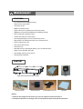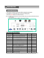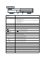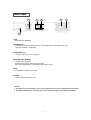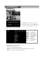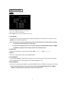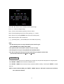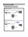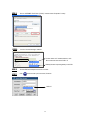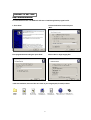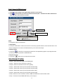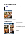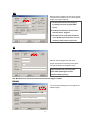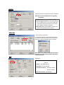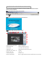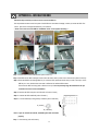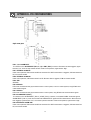
1
500W V1.2
Intelligent & Triplex
4CH MPEG-2 DVS
500AW V1.0
WARNING
All the safety and operating instructions should be read before operation.
The improper operation may cause permanent damage.
• This adaptor is only for this machine.
Do not use it for other electronic products or it will damage other products.
• Please lift and place this equipment gently.
• Do not expose this equipment to direct sunlight.
,
• Do not use this equipment near water or in contact with water.
• Do not spill liquid of any kind on the equipment.
• Please power down the unit before unplugging.
• Do not block the ventilation holes at the top and bottom of the unit.
• Do not switch the Power On & Off within short period of time
(within 3 seconds).
• Installation should be made by qualified service personnel.
The lightning flash with arrowhead symbol, within an
equilateral triangle, is intended to alert the user to the
presence of uninsulated "dangerous voltage" within the
product's enclosure that may be of sufficient magnitude to
constitute a risk of electric shock to persons.
The exclamation point within an equilateral triangle is
intended to alert the user to the presence of important
operating and maintenance-(servicing) instructions in the
literature accompanying the appliance.
TABLE OF CONTENTS
1. What do you get ?
FEATURES
PACKAGE CONTENT
SPECIFICATIONS
2. Before Operation
INSTALLATION GUIDE
FRONT PANEL
REAR PANEL
3. Basic Operation
GETTING STARTED
OPERATION
RECORDING FUNCTION
PLAYBACK FUNCTION
4. Detailed Menu Setup
MAIN MENU
MENU OPTIONS
RECORD SETTING
TIMER SETUP
CAMERA SETTING
DETECTION SETTING
DISPLAY SETTING
PIP SETUP
DWELL SETUP
USER SETTING
SYSTEM SETTING
BUZZER SETUP
UPGRADE SETUP
EVENT SETTING
NETWORK
PTZ
RETR
5. Advanced Operation
OPERATION OPTIONS
2X ZOOM
VIDEO LOSS
SEARCH MODE
USB BACKUP
KEY LOCK
6. Network setting guide
HARDWARE CONNECTION AT SERVER SIDE
SOFTWARD INSTALLATION
LOCAL SETTING
STATIC IP SETTING
DYNAMIC IP SETTING
SOFTWARE OPERATION AT CLIENT SIDE
INTRODUCTION OF BASIC OPERATION
PLAYBACK OPERATION
ADVANCED SETTING
CONNECT VIDEO WEB SERVER VIA IE BROWSER
7. F & Q
TROUBLESHOOTING
8. APPENDIX
APPENDIX A – INSTALL THE HDD
APPENDIX B – REPLACE THE HDD
APPENDIX C –RECORDING SPEED
APPENDIX D – PIN CONFIGURATIONS
1
1
2
3
4
5
6
7
7
7
9
10
10
11
12
13
15
16
17
17
18
19
19
20
20
21
21
22
22
22
23
24
25
26
27
28
30
31
39
39
40
41
44
45
46
47
47
48
What do you get ?
FEATURES
•
R.E.T.R (Remote Event Trigger Recording)
•
Remote control via the internet
•
Control PTZ camera
•
MPEG-2 compression format
•
Triplex function (record, playback and live at the same time)
•
USB Backup ( backup files by USB Sticker and USB HDD devices)
•
More accurate motion detection function
•
Connect video web server via IE browser
•
Auto sending message by e-mail or FTP when alarm occurs
•
High resolution: 720 X 480 pixels <NTSC> 720 x 576 pixels <PAL>
•
Picture-in-Picture (PIP) in live
•
Alarm input & output function
•
Linear Zoom (2x)
•
Recording rate: Up to 30 frames/sec (NTSC) ; Up to 25 frames/sec (PAL)
•
Support 1 removable HDD, IDE TYPE.
•
Quick multiple search by event / time list
•
Security password protection
CONTENT
Digital Video Recorder(with HDD cartridge)
Accessories pack
2 Keys
User’s Manual
Accessories pack
Power Adapter and Cord
CD-ROM
Warning:
1. Please check the package to make sure that you receive the complete accessories shown above.
2. The adaptor is DC19V 2A. If it is damaged, users can find replacement adaptor locally with this specification.
1
SPECIFICATIONS
Specifications are subject to change without notice.
Video format
NTSC/EIA or PAL/CCIR
Hard disk storage
IDE type, UDMA 66, supported 400 GB HDD
Camera Input Signal
Composite video signal 1 Vp-p 75Ω BNC, 4 channels
Network Interface
Ethernet (10/100 Base-T)
Protocals
TCP/IP, ICMP, SMTP, HTTP, FTP
Resolution
720 x 480 pixels <NTSC> , 720x576 pixels <PAL>
Recording Mode
Manual / Timer / Alarm (Remote) / Motion (Remote)
Main Monitor Output
Composite video signal 1 Vp-p 75Ω BNC
Call Monitor Output
Composite video signal 1 Vp-p 75Ω BNC
Motion Detect Area
16 * 12 targets per camera
Motion Detect Sensitivity
16 levels
Video Loss Detection
Yes
USB Interface
1 port. Support USB 1.1 Device
Refresh Rate
120 frames/sec. for NTSC / 100 frames/sec. for PAL*
Recording Rate
Up to 30 frames/sec. for NTSC / 25 frames/sec. for PAL
Dwell Time
Programmable (0~24 Sec)
Picture in Picture
Yes
Key Lock
Yes
Picture Zoom
2X
Camera Title
8 letters
Video Adjustable
Hue/ Color/ Contrast/ Brightness Adjustable
Alarm Input
TTL input, Hi (5V), Low (GND)
Alarm Output
COM./N.O/N.C
Trigger & Action
E-Mail images or images uploading to FTP site's specific
account/ Remote Recording
Web Interface
Yes
Time Display Format
YY/MM/DD, DD/MM/YY, MM/DD/YY, OFF
Power Source
DC 19V
Power Consumption
<32W
Operation Temperature
10℃~ 40℃ (32℉~104℉)
Dimension (mm)
343(W) x 223(L) x 59(H)
NTSC: 4CH x 30IPS = 120 frames/sec, PAL: 4CH x 25IPS = 100 frames/sec
2
Before Operation
INSTALLATION GUIDE
1. Table below is an example of connecting the DVR to existing Observation System.
2. Install HDD (The compatible HDD models are listed in the following table).
Please refer to page 46 Appendix A for installation instructions.
Note: 1. The HDD must be installed before turning on the DVR. If HDD is not installed, the DVR would function as
a 4 CH multiplexer.
2. Users need to set the HDD on the Master mode for system detecting.
COMPATIBLE HARD DISK MODELS
Manufacturer
Capacity
Rotation
Deskstar 180 GXP (120 GB)
Deskstar 7K250, HDS722516VLAT20
Deskstar 7K250, HDS722525VLAT80
120GB
160GB
250GB
7200 rpm
7200 rpm
7200 rpm
Deskstar 120GXP (80GB)
80GB
7200 rpm
IBM
Maxtor
Maxtor
Deskstar 120GXP (120GB)
DiamondMax 536DX(60GB) 4W060H4
DiamondMax Plus 9
120GB
60GB
80GB
7200 rpm
5400 rpm
7200 rpm
Maxtor
Maxtor
Maxtor
Seagate
Seagate
Seagate
DiamondMax Plus 9, Model#6Y120L
DiamondMax Plus 9, Model#6Y160L0
120GB
160GB
250GB
80GB
120GB
160GB
7200 rpm
7200 rpm
7200 rpm
7200 rpm
7200 rpm
7200 rpm
Western Digital Caviar WD1200BB-00CAA1
Western Digital Caviar WD2000BB-00DWA0
120GB
200GB
7200 rpm
7200 rpm
Western Digital CaviarSE WD2500JB
250GB
7200 rpm
HITACHI
HITACHI
HITACHI
IBM
Model
MaxLine Plus Ⅱ, Model#7Y250P0
Barracuda ATA IV, ST380021A
Barracuda ATA V, ST3120023A
Barracuda 7200.7 Plus, ST3160023A
NOTE: For non-stop long-time recording, we suggest to have two HDDs for recording to ensure good reliability of HDD.
3
FRONT PANEL
1
1. REMOVABLE HDD CARTRIDGE
& KEYHOLE
2
Please refer to page 47 Appendix #B.
2. CONTROL PANEL
LED LIGHT
The LED Light is ON under the following conditions.
•HDD : HDD is reading or recording.
•HDD Full : HDD is full .
•ALARM : To turn off the ALARM LED light, please refer to page 14 and set the ALARM mode as OFF.
•TIMER : When Timer is Enabled.
•PLAY : Playing mode.
•REC : Recording mode.
MENU
Press MENU button to enter main menu.
ENTER
Press ENTER button for confirmation.
SEARCH
Press SEARCH button for searching recorded video.
Zoom
Press ZOOM button to enlarge the picture display.
/ + PICTURE IN
PICTURE
/ - 4 CHANNELS
DISPLAY MODE
PIP: Press “PIP” button for Picture in Picture screen.
+ : Press “+ ” button can change the setting in the menu.
Press “
” button for 4 CH display modes and press twice to enter POP (Picture On Picture) function.
- : Press “ - ” button can change the setting in the menu.
SLOW
To slow down the speed of playing mode.
POWER
Press Power to turn ON / OFF the DVR.
FF / ►
•FF : Play video fast forward. (Press FF button again to adjust speed as 3, 45, 600 times)
• ► : Under setup mode, it works as Right button.
REW / ◄
•REW : Play video fast backward. (Press REW button again to adjust speed as 15, 90, 600 times).
• ◄ : Under setup mode, it works as Left button.
STOP / ▼
•STOP : Under DVR Recording / Playing mode, it can stop the action.
• ▼ : Under setup mode, it works as Down button.
PAUSE / ▲
•Pause : Under DVR playing mode, it can make the action pause.
• ▲ : Under setup mode, it works as Up button.
PLAY
Press “PLAY” button to playback recorded video.
REC
Press “REC” to start recording.
CAMERA SELECT (1-4)
Press the Camera Select (1-4) to select the camera.
ENTER + SEARCH
Press both “ENTER” and “SEARCH” buttons to enter the USB Backup Menu.
ENTER + ZOOM
Press both “ENTER” and “ZOOM” buttons to start the PTZ operation mode.
MENU + ENTER
Press both “”MENU” and “ENTER” buttons to Lock/Unlock the keyboard.
REC + STOP
Press both “”REC” and “STOP” buttons to inactivate RETR.
REC + PLAY
Press both “”REC” and “PLAY” buttons to activate RETR.
4
REAR PANEL
2
3
4
5
6
1
1. LAN
Connect DVR by LAN cable.
2. EXTERNAL I/O
•Controlled remotely by an external device or control system such as Video Web Server or PC.
•Alarm input, external I / O expansion.
3. VIDEO INPUT (1-4)
Connect to video source, such as camera.
4. MAIN AND CALL MONITOR
Connect to the main monitor.
Connect to CALL monitor. Show the Switch Display.
When alarm trigger happens, it will change to dwell modes of alarm.
5. FAN
For ventilation, do not block the opening.
6. POWER
Please use the provided power cord.
Warning:
1. The adaptor is only for this machine. Do not use it for other electronic product or it might damage other products.
2. The adaptor is DC19V 2A. If it is damaged, users can find replacement adaptor locally with this specification.
5
Basic Operation
GETTING STARTED
1.Connect the AC power cord and plug into an electrical outlet. The Red LED indicator light will be ON and the DVR is in
Standby mode.
2. Press the Power button. The POWER LED will turn from red to orange, and other red LED indicators will be turned ON.
It takes approximately 5 to 15 seconds to boot the system with the message : “ HDD Detecting ”. Once connected, the
POWER LED will change to color green, and the Alarm LED will be ON.
3. Before operating the DVR, set the system time first. (refer to page18).
NOTE : 1. If the HDD is not installed correctly or not installed, the “NO HDD!”, “HDD KEY UNLOCK!”, “UNKNOWN FILE
SYSTEM! PLEASE FORMAT IT!” messages will appear for 3 seconds, and then return to 4 CH Multiplexer display
mode.
*** “UNKNOWN FILE SYSTEM!”: The format of HDD is not accepted by the DVR system. The system only accepts
EXT3 format. Users can format HDD by selecting “HDD FORMAT” on SYSTEM menu.
2.. To switch the system, you need to turn off the power and pull out the AC power cord. Before you reconnect the
power, press “FF” to NTSC system or “REW” to PAL system and then reconnect to the AC power cord and then
the DVR will be auto-detecting.
(warning: Please confirm that the power of the machine is off before unplugging the power cord.
Moreover, if the power system is unstable, we suggest installing UPS .)
6
OPERATION
RECORDING
The DVR offers 2 recording modes(Timer and Manual). Under the recording status, if power is off accidentally, the
recorded video will still be stored in the HDD. DVR will return to previous original recording setting after power restores.
O/W
The first character: ( Frame/Sec)
A : 30 <NTSC> 25 <PAL>
B : 15 <NTSC> 12 <PAL>
C : 5 <NTSC> 4 <PAL>
The second character: (Record Quality)
a : Best b : High c :Normal d : Basic
007.2 GB: the capacity of HDD is available
O/W: HDD is overwritten
NOTE : Under O/W Recording mode, previously recorded files will be automatically overwritten.
1. TIMER RECORDING
Recording is scheduled by a Timer. It will indicate by the symbol
and
.
2. MANUAL RECORDING
Recording is initiated manually by pressing the REC button. Symbol
will be shown.
If the system is shut down, the system will resume recording automatically.
PLAY BACK
Press the “PLAY” and select the channel which you want to display on the middle of the screen and press the enter
bottom.
When users select the channel, users can also press the number buttons on the front panel.
Press “PIP” button to change the Location of channel
Press “ENTER” button to enlarge the video to
which users just set up.
full screen.
7
1. F.F. (FAST FORWARD) & F.R. (FAST REWIND)
Increase the speed of Fast Forward and Rewind on the DVR by pressing the “FF” button.
In the Play mode, press “ ► ” once to get 3X speed forward and press twice to get 45X speed,… and the maximum
speed to reach 600X.
Press “◄ ” once to get 15X speed rewind and press twice to get 90X speed, … and the maximum speed can reach
600X.
2. S.F. (SLOW FORWARD)
Slow down the speed of Forward on the DVR by pressing the “SLOW” button.
In the Play mode, press the “SLOW” button to enter the Slow mode.
Press ” SLOW ” once to get 1/4X speed forward and press “ ► ” to get 1/8 speed,… and the slowest speed can reach
1/16X.
3. PAUSE
The image will be motionless and displayed on the screen.
4. STOP
Press “STOP” button to stop displaying a video.
5. IMAGE JOG DIAL
It will allow you to view video frame-by-frame manually, one image at a time.
In PLAY mode, press “PAUSE ”, it will pause the video.
Press “ ► ” button advances one step.
Press “ ◄ ” button moves back one image.
NOTE: Under overwriting and duplex modes, when the playback motion is interrupted by unknown causes, please press
“Stop” and then the “PLAY” button to start playing again.
8
Detailed Menu Setup
MAIN MENU
Press “MENU” button to enter the main menu at first time.
The default password is 000000. Pleas press “ENTER” menu six
times to enter the menu when the password is default value.
There are 9 options available in the Main Menu.
RECORD -------- Record Scheduling
CAMERA -------- Camera Setup
DETECTION ---- Motion / Alarm Setup
DISPLAY -------- Display Mode Setup
USER ------------ User Password Setup
SYSTEM -------- System Setup
EVENT ---------- Event List
NETWORK ----- Network Setup
PTZ --------------- PTZ Camera Setup
RETR--------------RETR Setup
” “ ” : Move the cursor.
▲
•“▲” “▼” “
▲
The following buttons are used for menu setting :
• “ + ” and “ - ” : Select the numbers/ change values.
•ENTER : Enter a submenu mode / an option under a submenu for browsing / Confirm the selection.
•MENU : Enter the menu mode / Confirm the change/ Exit a menu.
9
MAIN OPTIONS
RECORD
▼
▼
Press the “▲” “▼” “ ” “
” buttons to move the cursor.
Press the “+” “-” buttons to change the digit.
Press the “MENU” button to confirm the changes/ to exit the menu.
1. STOP RECORD
The system will stop manual recording function during the recording period if the setting is “NO”. And then, press the
“ENTER” button to save the changed value.
Note: 1. The users have to stop recording function on this menu because the users cannot stop it by pressing
any front-panel buttons during the recording period.
2. On the Timer Recording mode, users have to either change the RECORD METHOD setting from TIMER
to MANUAL or change the timer setting to stop the timer recording function.
2. FRAME / SEC
Select the recording speed. The options are as following : NTSC-30、15 、 5 PAL-25、12 、4
3. QUALITY
There are four image qualities : BEST, HIGH, NORMAL, BASIC.
4. HDD OVERWRITE
To set the HDD OVERWRITE. When the HDD is going to be full under O/W recording mode, previously recorded files
will be overwritten without further warning notices if the HDD OVERWRITE is “ON”.
5. RECORD METHOD
There are two recording methods: MANUAL ( by pressing the “REC” button) and TIMER ( by setting the timer recording).
***On the Timer Recording mode, users have to either change the RECORD METHOD setting from TIMER to
MANUAL or change the timer setting to stop the timer recording function.
10
▼
Press the “▲” “▼” “ ” “
▼
TIMER SETUP
” buttons to move the cursor.
Press the “+” “-” buttons to change the digit.
Press the “MENU” button to confirm the changes/ to exit the menu.
1. DAY
Choose the day for recording. The options are:
MON(Monday) , TUE (Tuesday), WED (Wednesday), THR (Thursday), FRI (Friday), SAT (Saturday),SUN (Sunday),
MO-FR (Monday to Friday), SA-SU (Saturday to Sunday), OFF, and DAILY(on each day).
* Date could be changed by “+” and “-” buttons.
2. START
The beginning of recording time.
3. END
The end of recording time.
11
CAMERA
▼
▼
Press the “▲” “▼ “ ” “ ” buttons to move the cursor.
Press the “+” “-” buttons to change the option/digit.
Press the “MENU” button to confirm the changes/ to exit the menu.
1. TITLE
Assign a title to each channel. The default title is the camera’s number (Up to 8 characters).
2. REC (RECORD)
Select a channel to record.
ON : when the timer input is triggered, DVR will record a video.
OFF : DVR will not record.
3. BR (BRIGHTNESS)
Adjust the brightness of each channel. The level is from 0 to 63.
4. CT (CONTRAST)
Adjust the contrast of each channel. The level is from 0 to 63.
5. CL (COLOR)
Adjust the color of each channel. The level is from 0 to 63.
6. HUE (HUE)
Adjust the hue of each channel. The level is from 0 to 63.
7. CAMERA DEFAULT
The setting of BR/CT/CL/HUE will be back to the default value, which is 31.
12
▼
Press the “▲” “ ▼ ” “
“”
▼
DETECTION
“buttons to move the cursor.
Press the “+” “-” buttons to change the option.
Press the “MENU” button to confirm the changes/ to exit the menu.
1. DET (DETECTION)
The motion detection on each channel can be turned ON or OFF individually.
2. AREA
Press the “ENTER” button to set target-area.
In this function, it is defaulted to detect nothing.
After entering the setting, users will see the pink area, which means the undetected area, and users can set the area to
be detected, and which will turn from pink to transparent.
The Pink target represents the undetected area.
The Transparent target represents the Motion Detection Area.
The beginning of Motion Detection SettingNon activate area
Motion Detection Setting –
A row-target detected
Motion Detection Setting –
A detected target
: navigates between targets.
▼
▼
▲▼
Motion Detection SettingOne Target undetected
- : turns all targets on the screen ON/ OFF.
+ : press once to set a motion target, press twice to set a row of motion target..
13
3. LS (Level Sensitivity)
Comparing the difference between two images to allow the system to start motion detection function.
Lower number = higher sensitivity for motion detection. The highest sensitivity setting is 02, the lowest sensitivity setting
is 15. The default value is 06.
4. SS (Spatial Sensitivity)
Set the number of motion detection targets (from 0-192 target areas). The highest sensitivity setting is 0, and the lowest
sensitivity setting is 15. The default setting is 02.
Note:The setting of Spatial Sensitivity cannot be more than the number of targets set in the AREA.
5. TS (Temporal Sensitivity)
The system will start the motion detection function if the continuous fields are all different.
The highest sensitivity setting is 0, and the lowest sensitivity setting is 15. The default setting is 02.
6. RE (REFERENCE)
Set the Reference image to which the current screen is compared (from 0-63).
For example, the value 8 would compare the current image to the 8th previous image. The higher value will increase the
sensitivity. The default value is 10.
7. Alarm
Select LOW / OFF / HIGH for alarm polarity. The default alarm value is OFF.
8. Duration Time
You can set durative time of detection.(1, 2, 3, 4, 8, 24, 60), the default value is 02.
9. Day, Start, End of Duration
Choose the day for recording, the beginning of recording time and the end of recording time.
Note: When the motion detection function is triggered during the recording period. The symbol
will be
shown.
When the alarm function is triggered during the recording period. The symbol will be shown
14
.
DISPLAY
YES
▼
▼
Press the “▲” “ ▼ ” “ ” “ ” buttons to move the cursor.
Press the “+” “-” buttons to change the option/digit.
Press the “MENU” button to confirm the changes/ to exit the menu.
1. TITLE DISPLAY
Set the title showing on monitor.
2. OSD COLOR
Select the OSD (On Screen Display) color. The options are WHITE, RED, YELLOW, CYAN, BLUE, PINK, GRAY,
ORANGE.
3. CURSOR COLOR
Select the cursor color. The options are RED, YELLOW, GREEN, CYAN, BLUE, PINK, GRAY, ORANGE.
NOTE: The setting of OSD COLOR and CURSOR COLOR cannot be the same.
4. LOSS SCREEN
Select a way to display the screen when the video input is out of order. The options are BLACK, BLUE and RETAIN
(retain the last picture).
5. OSD POSITION
Select the OSD POSITION. The options are NORMAL (in upper right corner) or CENTER.
6. PLAYBACK METHOD
Select a video type to playback. The options are frame and field. 1 frame equals two fields.
7. PIP OPTION / DWELL OPTION(refer to p.16 and 17)
To enter the PIP setting menu/DWELL setting menu.
15
PIP OPTION
Press the “▲” “▼” buttons to move the cursor.
Press the “+” “-” buttons to change the option.
Press the “MENU” button to confirm the changes/ to exit the menu.
1. FULL SCREEN
The full screen background picture display.
2. PIP SCREEN
The picture with a 1/9 size screen “insert”.
3. POSITION
There are six position settings : D/L (Down/Left), D/M (Down/Middle), D/R (Down/Right), U/L (Up/Left), U/M (Up/Middle),
U/R (Up/Right).
16
DWELL OPTION
▼
▼
Press the “▲” “▼” “ ” “ ” buttons to move the cursor.
Press the “+” “-” buttons to change the option.
Press the “MENU” button to confirm the changes/ to exit the menu.
1. NORM
To set up the DWELL time period that each channel shows sequentially automatically on call monitor. The level is
from 01 to 24 Sec or OFF.
2. ALARM
To set up the DWELL time period when the alarm input is triggered.
The level is from 01 to 24 Sec or OFF.
▼
USER
▼
Press the “▲” “▼” “ ” “ ” buttons to move the cursor.
Press the “+” “-” buttons to change the option/digit.
Press the “MENU” button to confirm the changes/ to exit the menu.
1. USER
To set up the user’s account for controlling. It allows 7 users setting.
Supervisor – Control all the functions.
Other Users – View all functions except the menu setting and event list cleaning.
2. PASSWORD
To set the security password for each account.
The maximum length of user’s password is 6 digits.
NOTE: When you reset your DVR, please login as supervisor.
1. Unlock the keyboard.
2. Enter the password.
3. Lock the keyboard.
17
SYSTEM
▼
▼
Press the “▲” “▼” “ ” “ ” buttons to move the cursor.
Press the “+” “-”buttons t0 change the setting
Press the “MENU” button to confirm the changes/ to exit the menu
1. KEY MUTE
To set the KEY MUTE. When the setting is “ON”, there will be no sound when you press any key.
2. BUZZER (refer to page 19 )
To enter the buzzer setup menu.
3. MESSAGE LATCH
The default setting of messages displaying is 10 seconds when the setting is “ON”.
4. DATE DISPLAY
Set the date display. The options are Y/M/D, D/M/Y, M/D/Y and OFF.
5. DATE
Set the date.
6. TIME
Set the time.
7. HDD FORMAT
Format HDD by selecting “FORMATE” option. After formating the HDD, the system will restart.
Note: 1. The system will take about 12 minutes to format 80 GB HDD.
2. After formatting the HDD, you would find that the space about
12% is occupied.
8. SYSTEM RESET
Reset all system settings back to factory default setting.
9. LANGUAGE
Select one language for menu displaying. The options are ENGLISH and CHINESE. The system will automatically save
the setting.
10. UPGRADE(refer to page 19 )
To enter the upgrade setup menu.
18
BUZZER SETUP
1. BUZZER
Set the BUZZER “ON”, it will buzz when event occurs.
2. EXT ALARM
To set the EXT ALARM. It will be trigged by event occurrence when the setting is “ON”.
3. VLOSS ALARM
To set the VLOSS ALARM. When the setting is “ON”, the alarm will start after setting Buzzer, EXT Alarm or Alarm Duration.
4. MOTION ALARM
To set the MOTION ALARM. When the setting is “ON”, the alarm will start after setting Buzzer and EXT Alarm.
UPGRADE SETUP
Note: 1.Please ask your agent to get the latest firmware.
2.The file name is “ug784.dat”. Please do not change the file name.
3. If you save it in the USB. Do not put it in the folder.
Users can upgrade the DVR software by USB memory device.
YES: Upgrade
No : Cancel
It will take few minutes to upgrade the whole system. Users cannot unplug the power cord, or turn off the power during
the period of upgrading.
The whole system setting will be disable when the system is upgrading.
Therefore, users have to reset all settings after upgrading.
CHECK CRC: The system will check the firmware status to ensure the quality of system.
19
EVENT
Press the “▲” “▼” buttons to move the cursor.
Press the “ENTER” button to get into the submenu.
The EVENT shows the recording list of different types.
The VIDEO LOSS section lists the record of video loss.
The ALARM LOG section lists the record of triggering by external I/O alarm.
The MOTION LOG section lists the record of triggering by motion detection.
The ALL LOG section lists all types of records.
The DELETE ALL option will delete all records.
▼
▼
A single page can display 12 recorded events.
Press “
” or “
” button to change the pages.
Note: The event list show 256 item at most. When the list is over 256, it will overwrite automatically.
PWR RESET: The system will automatically record when the system has been reset.
▼
Press the “▲” “▼” “ ” “
▼
NETWORK
” buttons to move the cursor.
Press the “ + ” “ - ” buttons to change the digit.
Press the “MENU” button to confirm the changes/ to exit the menu.
Set IP ADDRESS, NETMASK, GATEWAY, DNS and PORT.
Choose YES in LOAD DEFAULT will go back to default value of NETWORK.
20
▼
Press the “▲” “▼” “
”“
▼
PTZ
” buttons to move the cursor.
Press the “+” “-” buttons to change the digit.
Press the “ENTER” button to confirm the changes/ “MENU” to exit the
menu.
1.Please press ENTER after set NEW ID, then the CURRENT ID and NEW ID will change to the same number which
you have set.
2.When the PTZ had been installed, you can see the ID of PTZ on the Screen. Please check that the ID is the same as
the ID displayed in PTZ MENU.
RETR
Press the “▲” “▼” buttons to move the cursor.
Press the “+” “-” buttons to change the digit.
Press the “MENU” button to confirm the changes/ to exit the menu.
Remote Event Trigger Recording is only for PC. When motion-triggered event is detected under R.E.T.R mode,
a video playback recording motion event will be transferred and saved on the desktop of computer.
1.MODE
You can choose the display mode when the event is triggered.
2.RETR DELAY
The RETR DELAY section lists 3 delaying settings, including “03MIN”,”05MIN” and “10 MIN”.
3.Control RETR via AP
You can control RETR via AP. Please click “R.E.T.R.” button to activate it.
Note : 1. When you activate it, the color of the button “R.E.T.R.” is red.
2. If you want to return to control RETR via DVR’s panel. Please click “R.E.T.R.” button and enter the password.
The color the button “R.E.T.R.” is blue, when you inactivate it.
21
Advanced Operation
OPERATION OPTIONS
2X ZOOM
Press the “ZOOM” button, It displays zoomed picture on main picture and a small inserted window.
The inserted window contains a movable 1/4 view size of the appointed camera. The range is 2X.
2004 MAY-27 [THU] PM 01:45:37
the “ZOOM” button again to exit the zoom pointer.
• Press Camera 1-4 button to select a channel.
• Press ▲▼
buttons to move the zoom position.
• Press
▼
▼
CAMERA01
VIDEO LOSS
The screen will display “ VLOSS” in the center of display picture, if the video input is not connected properly.
22
SEARCH
Press “SEARCH” button to play the recording.
Select a channel for searching a video record.
Press “▲” “▼” buttons to select camera.
Press the “ENTER” button to get into menu/ submenu
Press the “MENU” button to confirm the changes/exit the menu
SEARCH MODE
Press the “ENTER” button to get into each submenu.
1. EVENT SEARCH
Display all the videos, which have been motion triggered on the recording mode.
Note : When you playback recorded video, it would play with fast speed. And when you press “PLAY” button, it would
return to normal speed.
2. TIME SEARCH
Enter a period recording for searching a video.
Press “ENTER” button to move to next digit.
Press “+” “-” button to change the digit.
•Select
Enter a period of time for searching a video.
If the users enter a inexistent period, it will show “PRESS MENU KEY TO RETURN”.
After enter the “MENU” button, the screen will back to the previous screen.
23
3. LIST ALL
List all video records.
Press the “▲” “▼” buttons to select one record.
Press the “ENTER” / “PLAY” buttons to display.
1. Y/M/D
The Month and the Date display(Year/Month/Date).
2. HO:MI:SE
The beginning of recording time(Hour:Minute:Second).
3. MI:SE
The duration of playing time(Minute:Second).
4. TYPE
D1: Multiplex mode (input images of a channel at a time).
USB BACKUP
Users may have to format the USB memory device( USB Sticker and USB HDD devices ) by PC before connecting to the DVR.
Press both “ENTER”+ “SEARCH” buttons, enter the USB BACKUP mode.
Users can save files into the USB memory device, and read files by personal computer.
The system will detect the USB memory device automatically. it will show “DETECTING USB DEVICE”
Inside of the symbol [ ] shows the available space of the USB memory device.
24
Press “◄” “►” buttons to select a channel or move to the next digit.
Press “+” “-” buttons to change the digit.
Step 1: Choose a certain camera by pressing “◄” “►” buttons.
Step 2: Enter the beginning and the end of time by pressing “+” “-” buttons.
Step 3: Select OK by pressing “ENTER” button (shows the recording space).
Step 4: Select OK again to start to backup a file.
[ ]/[ ]: [ Recording space ] / [ Total available space of the USB memory device ].
NOTE:
1. The USB memory device can only be detected by these three file types:
FAT32 (WINDOWS), EXT3 (LINUX), EXT2 (LINUX)
2. The system will take a few minutes to search if the file is too large.
3. The backup files can only be read by WinDVD and PowerDVD software.
4. The 4CH recording mode will play as four times speed when you playback recorded video.
( The same does 3CH and 2CH. 3CHàtriple. 2CHàdouble.)
KEY LOCK
For advanced security, users can “Lock” the buttons on your DVR. Key-Lock prevents other people from using the system.
Press “ENTER” + “MENU” at the same time to enable Key Lock.
Press “ENTER” + “MENU” at the same time and key in password (Default : 000000), and then press “ENTER“ to disable
Key Lock.
NOTE: To switch to different USER, press “ENTER” + “MENU” buttons to “KEY LOCK” and then enter the different
user’s password to UNLOCK.
25
Network Setting Guide
HARDWARE CONNECTION AT SERVER SIDE
u Direct Connect with PC
CAMERA
PC
MONITOR
uRemote Connect Via Internet
CAMERA
MONITOR
26
PC
SOFTWARE INSTALLATION
1.Put the attached CD into a CD-ROM and it will start to install the application program into PC.
2. Press “Next”.
3.Choose destination location and press “Next”.
4.Set program shortcuts setting and press “Next”.
5.Press “Next” to begin to copy files
6.After the installation, there are 6 files and 1 folder in your assigned path (file folder) as below.
27
LOCAL SETTING
Local Area Network Setting
Step 1
Please enter the net work menu and get the IP Address of this DVR.
192.168.001.010
255.255.255.000
192.168.001.065
168.095.192.001
00060
No
Step 2
Network setting for PC. (The instruction is based on Win XP O/S. If your O/S is Win 2000 or Win
2003, the setup procedure is similar to that of Win XP O/S)
Click
Step 3
Click “Properties” for TCP/IP setup
28
Local Area Connection Enabled
Realtek RTL8139 Family
twice
STEP 4
Click on “INTERNET PROTOCAL (TCP/IP)” and then select “Properties” to setup
STEP 5
Choose “Use the following IP address”
The last number of IP address between 1-255.
○ Obtain an IP address automatically
● Use the following IP address:
192.
168 .
1 . 11
192.
168 .
1 . 65
But it cannot the same as the DVR’s IP.
Gateway Number equal the gateway in the DVR.
STEP 6
Connect DVR and Computer with cross over cable
STEP 7
Click
twice and enter your User name, Password
192.
168 .
DVR’s IP
1 . 10
29
STATIC IP SETTING
Step1 : Static IP setting
In DVR MENU / NETWORK set IP ADDRESS, GATEWAY, NET MASK, DNS and WEB PORT which are provided
from your local ISP ( internet service provider ).
For example
After all network settings are finished, please connect DVR and static IP.
Static IP
Step2 : Connect PC and DVR via internet
Click
twice and enter your User name, Password
(Note : If you never change the “Account” before, the
User Name and Password are both “admin”) and Server
IP which you have set to DVR in step 2. Then click OK to
connect.
30
DYNAMIC IP SETTING
Step1 : Software installation
1.Put the attached CD into a CD-ROM and it will start to install the application program into PC.
2. Press “Next”.
3.Choose destination location and press
“Next”.
4.Set program shortcuts setting and press “Next”.
5.Press “Next” to begin copying files
6.After the installation, there are 6 files and 1 folder in your assigned path (file folder) as below.
31
Step2 : DDNS apply
1. Click on free site
“http://www.dyndns.org” ( please
look at the example below, you can
also apply DDNS in other DDNS web
page) and “Account”.
2. Press “Create Account”.
3. Register the information and click on
“Create Account”
4.After registering your account, you will receive an e-mail, which contains instructions to activate your account.
If you do not follow these directions within 48 hours, you will need to re-register your account.
5.Login your account.
6.Click on“Account” and “Add Host”
7 Users can set up their own DDNS HOST.
For example, the user’s applied Host
name is “test.dyndns.org”. And then
press “Add Host” to finish the setting.
(NOTE : Some routers don’t support
some DDNS HOST)
test
test
32
Step3 : Login router
NOTE : The following settings are different from router to router. Please read the instruction of your router
thoroughly.
1.Connect PC and router (LAN end)
LAN end
POWER
2. Network setting for PC. (The instruction is based on Win XP O/S. If your O/S is Win 2000 or Win 2003, the
setup procedure is similar to that of Win XP O/S)
Click
3.Click “Properties” for TCP/IP setup
33
Local Area Connection Enabled
Realtek RTL8139 Family
twice
4.Click on “INTERNET PROTOCAL (TCP/IP)” and then select “Properties” to setup
5.Choose “Obtain an IP address automatically”
6. Enter “Command Prompt”
34
7. In the setting window, enter “ ipconfig” to write down router’s gateway(e.q. 192.168.1.1)
8. Close the window in the above step. Enter the IP address ( router’s gateway : 192.168.1.1 ) to log in to the router
from internet explore. And then enter the login web page and key in the router’s user name and password.
Step3 : Router setting
NOTE : In the router setting, we have four steps as follows.
1. Dial setting
2. DHCP setting
3. Virtual server setting
4. DDNS setting
35
1. Press “INTERNER PORT” and choose your WAN type (e.q. PPPoE), and then enter your “User Name” and
“Password” of dialing up to dynamic IP.
Press save after you finish the set up.
test
test
2. Press “LOCAL PORT” and set “Start IP address” and “Number of IP address”.
(For example, if the IP address of DVR is 192.168.1.10, then 10 is excluded from the setting range) Press save
after you finish setting up.
3. In “ADVANCED SETUP / Virtual Server”. Choose “By Port” and set “Port Number” to 80 for DVR. And set
“Local Server IP Address” to 192.168.1.10.
Press add after you finish the set up.
36
4. In “ADVANCED SETUP / Dynamic DNS”. Key in the “DNS Account”, “User Name” and “Password” that you
applied in step 3. Press save after you finish the set up.
test
Step4 : IP setting
In DVR MENU / NETWORK set SERVER IP, GATEWAY, NET MASK, DNS and WEB PORT.
Please get the number of IP ADDRESS, NETMASK, GATEWAY,
DNS, PORT, LOAD DEFAULT from your ISP company.
Step5 : Connect router
ADSL modem
(WAN end)
37
Step6 : Connect to DMR via internet
1. Change PC network setting to the original setting and link PC to the internet.
2. Click
twice and enter your User name, Password and host (Note : The default User Name and Password
are both “admin”). Then click OK to connect.
test. Dyndns.org
Backup Program
Play the last record file
admin
test.dyndns.org
NOTE:
You can get the software via attached CD.
vAddress Book
You can press “Address Book” button to add a new IP or choose any logined IP address to access the Video Server. This
function is designed to store the list of IP addresses which you can control and manage.
vBackup Program
You can press “
” button and you can backup all related files of this application program to any storage device that
you want (for example: any hard disk or USB Flash Drive).
vPlay last record file
You can press “
” button and you can play the last record file.
Note of Dynamic IP setting
*In step 2.7 : Some routers don’t support some DDNS HOST.
*In step 3.1 : Please use router’s LAN end to connect PC.
*In step 3.8 : Please use IE browser to enter router’s gateway.
*In step 4.1 : Please make sure that you have pressed save after setting.
*In step 4.2 : Please make sure that you have pressed save after setting.
*In step 4.3 : Please make sure that you have pressed add after setting.
*In step 4.4 : Please make sure that you have pressed save after setting.
*In step 6 : Please use router’s LAN end to connect to DMR. Use WAN end to connect to ADSL modem.
*In step 7 : The Server IP is the DDNS HOST which you set in step 4.4.
38
SOFTWARE OPERATION AT CLIENT SIDE
Follow the steps for connection at your client site (remote site).
Step 1:Click
twice to enter Login setup (please refer to page 18“software installation”)
Step 2:Key in “User Name” and “ Password”. Click “OK” to establish the connection.
Step 3:If you could see the video screen as following, you have been connecting successfully to the server.
2004-DEC-23 [ THU ] 10:42:32 Aa 001.9 GB O/W
CAMERA01
CAMERA02
CAMERA04
CAMERA03
2004-NOV-18 15:58:36
INTRODUCTION OF BASIC OPERATION
A. Video Web Server control panel
1
2
3
4
5
6
7
8
9
10
1. Image transmission rate per second
2. Data transmission rate
3. Connection/Disconnection
4. Resolution : D1、CIF
5. Image quality : High、Middle、Low
2004-DEC-23 [ THU ] 10:42:32 Aa 001.9 GB O/W
6. Image adjusting : Brightness/ Contrast/ Saturation
7. Snapshot : press this button, the image will be
automatically saved in the PC.
CAMERA01
CAMERA02
8. Record : press this button, the recording file will
be saved in the PC automatically.
9. System Config
10. Number of online users
CAMERA03
CAMERA04
39
B. Digital device control panel
8
7
1
2
3
4
6
1. CH1-4
5
9
* +/-:
2. PIP/+, QUAD/- *
Press “+” or “-” to change the default value.
3. Zoom, Lock, Record, Search
**TURBO:
4. Stop, Rewind, Fast Forward , Pause,
Activate the turbo button when you would like to shift the
selection more quickly by jumping 6 selections at a time.
Slow, Play
5. Menu / up / down / left / right
NOTE:
6. PTZ
After you press the record icon, there will be a recording file in
the path that you have set. Each recording file can be save up
to 6000 frames. The recording file will be assigned to the
second file if it is more than 6000 frames. Besides, if the HDD
space is less than 200MB, the program will stop recording.
7.Enter
8.TURBO**
9.R.E.T.R.
PLAYBACK OPERATION
Please find a recording file in the PC and click twice on it to playback.
1
2 3 4
5 6 7 8 9 10 1112
13
1. On Screen Display
2. Snapshot
3. Stop
2004/12/23 11:25:39
100 % CH1
2004-DEC-23 [THU] 11:22:05
Aa 001.6 GB O/W
4. Pause
5. Slow (1/2, 1/4, 1/8, 1/16, 1/32)
6. PLAY
7. Fast
CAMERA01
8. OSD show / hide
CAMERA02
9. Config Setting
10. Open Last File
11. Open Next File
CAMERA03
PAL_CIF
CAMERA0427
192.168.1.49
40
12. Duration time / Status
13. Playback controlling bar
ADVANCED SETTING
Click “SYSTEM CONFIG” for advanced setting.
SYSTEM CONFIG
NOTE :
Apply-After changing all setting, press “apply” to refresh the data.
Reboot-Press this button to restart setting.
ACCOUNT
Set up the user’s account( Max 10 accounts) , password
and authority ( Max 5 accounts on line at the same time) .
1.User’s level:
SUPERVISOR-control all the functions
HIGH LEVEL-control advanced functions
NORMAL -control basic functions only
GUEST LEVEL –watch the image only
2.Life time : During the period of time,
users are allowed to control the Video
Web Server.
ALARM
Set up the ALARM function. You can use it to
operate “alarm trigger recording” function.
1.Alarm Trigger: Enable or disable Alarm trigger
function.
2.Alarm Method : Two selections—E-mail or FTP.
3.Image Resolution : Image storing resolution for
Email or FTP function.
(CIF is 176*144; D1 is 352*288)
4.Alarm refresh : Clean the alarm message “
”
which is showed on the screen.
41
MAIL
When the alarm is triggered, the video server program
will capture the instant picture and e-mail the captured
image to the assigned recipients.
1. Get all the data from the ISP company or
by mailing to the server supplier.(SMTP
server)
2. Set the mail list which you want to send to
when the alarm is triggered.
3. No matter you set up the verify password or
not, it depend on your mail server. If it is not
necessary. Please choose verify as “No”.
FTP
When the alarm is triggered, the video server
program will capture the instant picture and upload
the captured image to the assigned FTP site.
1.Get all the data from your FTP provider.
2.The default uploading port is No.21.
3.Set the uploading directory.
Note: Mail function and FTP fuction would work when the alarm trigger is enabled.
File Path
You can modify the storing path for recording file and
snapshot images.
C:\ Documents and Settings\test\desktop
C:\ Documents and Settings\test\desktop
42
TOOLBOX
Upgrade the firmware and get the online users’ information.
NOTE :Do not reboot the DVR while it is upgrading
the firmware.
1.Firmware Version : The current firmware version.
2. Find and upgrade Firmware: Please get the firmware
from your agent and save it in your PC or USB. Press
“Find” button to get the latest firmware from PC and
press “Upgrade_Firmware” to upgrade it.
3.Turbo Step: Set the shift step when you shift the zone
which you see during the zoom in function.
Online User
1.The information of online user.
2. Chat function. Users are on line at the same time and
two of them can talk to each other. Click the name of the
other user. A window as below will jump out. Click OK.
NOTE: Please turn (activate) all transmission TCP and
UDP ports. Fire wall and similar software may disrupt
normal transmission.
RETR
RETR setup.
1. Remote Record : please click “Enable”
to start it.
2. Quality : High, Middle and Low.
3. Resolution : 704*576, 352*288。
4. Connection Check IP : check the connection
situation of network.
5. R.E.T.R. Time Limit : end time setup.
43
CONNECT VIDEO WEB SERVER VIA IE BROWSER
You can also connect Video Web Server via browser. This function is suitable in both WIN 2000 and WIN XP
( WIN XP is preferable to WIN 2000)
Step 1:Enter IP address that you want to connect.(example)
http://61.66.138.74
Step 2:Enter your Username and Password to login Video Web Server.
Step 3:After you login, you will see as below. (example)
3 4
2
5
6
7
8
9
1
10
11
12
13
14
15
1.Image transmission rate per second
9.Quality switching button
2.Data transmission rate
10.Menu, Left, Right, Up, Down, Exit
3.Video Channel
11.Lock, Enter, Zoom, Search, Select.
4. Resolution :D1、CIF
12.Stop, Play, Record, Rew, Fast, Pause, Slow,
5.Image quality : High、Middle、Low
13.Camera
6.Number of online users
14.4cut, PIP
7.Channel switching button
15.Position of view
8.Resolution switching button
Note: If you control the DVR via IE Browser, the RETR function can not be worked.
44
F&Q
TROUBLESHOOTING
When malfunction occurs, it may not be serious and can be corrected easily. The table below describes some typical
problems and their solutions. Please check them before calling your DVR dealer.
PROBLEM
No power
SOLUTION
l
Check power cord connections.
l
Confirm that there is power at the outlet.
Not working when press ing any
button
l
Check if it is under Key Lock m ode.
l
Press "MENU" & "ENTER" to exit Key Lock m ode.
No recorded video
l
Check if the HDD is ins talled properly.
Tim er Record enable does not
working
l
Check if the Record Enable is s et to YES
No live video
l
Check cam era video cable and connections .
l
Check m onitor video cable and connections .
l
Confirm that the cam era has power.
l
Check the s etting of cam era lens .
NTSC & PAL Sys tem s witch
To s witch the s ystem , pres s “FF” to NTSC sys tem and “REW” to
PAL s ys tem. (Refer to Page 6 "GETTING STARTED". )
Under overwritting and duplex
m odes , the playback m otion is
interrupted
please pres s “STOP” button and then the “PLAY” button to play
again
45
APPENDIX A– INSTALL THE HDD
Follow the steps carefully in order to ensure correct installation.
The compartment located on the front panel of the DVR is the removable Cartridge, in which you insert the HDD. The
various parts of the Cartridge are labeled for your reference.
***Note: Users need to set the HDD on the Master mode for the system detecting.***
Step 1 Connect the connector with the HDD (refer to Picture 1).
Step 2 Put HDD into the HDD cartridge. Please notice the bottom side is power side as chart shows (refer to Picture 2).
Step 3 Screw the HDD to the cartridge. Before you screw the HDD, please be aware that you must to level pin 1 of the
HDD at pin 1 mark, because the screw hole is different from different HDD brands.
Then screw the HDD correctly (refer to Picture 3 and 4). You must precisely align the hard disk to the pin
connection to ensure correct installation.
Step 4 Reverse the HDD and put it into DVR (refer to Picture 5 and 6).
Step 5 Connect the HDD with DVR (refer to Picture 7).
Step 6 Lock the cabinet by turning the key clockwise (refer to Picture 8).
A ( locked )
B ( unlocked )
Note : If you do not lock the cabinet, the DVR system will not function
properly.
Step 7 Close the cap (refer to Picture 9).
46
APPENDIX B– REPLACE THE HDD
A ( locked )
B ( unlocked )
Step 1 Open the cap
Step 2 Unlock the cabinet by turning
the key anti-clockwise
Step 3 Pull out the cartridge
Step 4 Loosen all screws on
the Cartridge
Step 5
Note: 1. If you want to change a different HDD, you must remove the connectors from HDD ( refer to Page 44 ).
2. When HDD works for a period of time, the surface temperature will be high, please pay attention to it.
3. After turning the key to unlock position, please wait for several seconds until HDD operation stop
completely.
HDD HOT SWAP FUNCTION
Please follow the steps as following to ensure the reliability.
1)Unlock the cabinet by turning the key anti-clockwise.
2)Key in your password and press enter to disable the hard drive.
3)Pull out the HDD cartridge.
4)Replace the HDD in the tray.
Note: After turning the key to unlocked position, please wait for several seconds till HDD operation stops completely.
APPENDIX C– RECORDING SPEED
The Recording Time is different based on Recording Speed, Recording Quality and Recording Mode.
Please refer to following table. HDD capability is 250GB.
PAL SYSTEM
NTSC SYSTEM
IPS
Multiplex
Mode
HDD Type
Best
High
Normal
Basic
30
106hr
132hr
213hr
326hr
15
212hr
264hr
426hr
652hr
5
636hr
792hr
1278hr
1956hr
IPS
Multiplex
Mode
250 GB
HDD Type
47
Best
High
Normal
Basic
25
106hr
132hr
213hr
326hr
12
212hr
264hr
426hr
652hr
250 GB
4
636hr
792hr
1278hr
1956hr
APPENDIX D– PIN CONFIGURATIONS
15 pin com port
DVR
9 pin com port
DVR
PIN 3, 4, 5, 6 ALARM INPUT
To connect wire from ALARM INPUT (PIN 3, 4, 5, 6) to GND ( PIN 9 ) connector. When alarm has been triggered, signal
becomes “Low”, and it will stop all alarm activities. Under normal operation, signal remains “High”.
PIN 7. EXTERNAL ALARM NC
Under normal operation COM connect with NC and disconnect from NO. But when alarm is triggered, COM disconnect with
NC, and connect with NO.
PIN 8. EXTERNAL ALARM NO
Under normal operation, COM will disconnect from NO. But when Alarm is triggered, COM will connect with NO.
PIN 9. GND
GROUND
PIN 10. RS485-B
DVR can be controlled remotely by an external device or control system, such as a control keyboard, using RS-485 serial
communications signals.
PIN 11. RS485-A
DVR can be controlled remotely by an external device or control system, using RS-485 serial communications signals.
PIN 14. ALARM RESET (INPUT)
To connect wire from ALARM RESET ( PIN 14 ) to GND ( PIN 9 ) connector, it can disable ALARM. An external signal to
ALARM RESET ( PIN 14 ) can be used to reset both ALARM OUTPUT signal and DVR’s internal buzzer. When alarm has
been triggered, signal becomes “Low”, and it will stop all alarm activities. Under normal operation, signal remains “High”.
PIN 15. EXTERNAL ALARM COM
Under normal operation COM connect with NC and disconnect from NO. But when alarm is triggered, COM disconnect from
NC, and connect with NO.
48