1
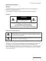
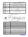
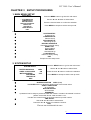
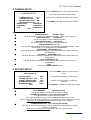
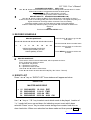
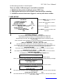
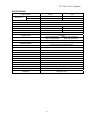
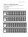
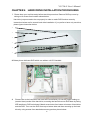
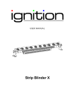
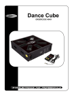
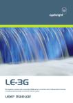
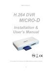
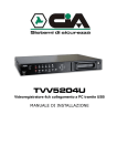
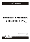
VG 704-L User’s Manual
VG 704-L USER’S
MANUAL
4 CHANNELS
NETWORK DIGITAL VIDEO RECORDER
VG 704-L User’s Manual
INSTRUCTION MANUAL
To obtain the best performance and ensure device function correctly, please read this
instruction manual carefully and completely.
FCC Compliance
USER-INSTALLER CAUTION: YOUR AUTHORITY TO OPERATE THIS FCC VERIFIED
EQUIPMENT COULD BE VOIDED IF YOU MAKE CHANGES OR MODIFICATIONS NOT
EXPRESSLY APPROVED BY THE PARTY RESPONSIBLE FOR COMPLIANCE TO PART
15 OF THE FCC RULES.
NOTE: THIS EQUIPMENT HAS BEEN TESTED AND FOUND TO COMPLY WITH THE
LIMITS FOR A CLASS A DIGITAL DEVICE, PURSUANT TO PART 15 OF THE FCC RULES.
THESE LIMITS ARE DESIGNED TO PROVIDE REASONABLE PROTECTION AGAINST
HARMFUL INTERFERENCE WHEN THE EQUIPMENT IS OPERATED IN A COMMERCIAL
ENVIRONMENT. THIS EQUIPMENT GENERATES, USES, AND CAN RADIATE RADIO
FREQUENCY ENERGY AND IF NOT INSTALLED AND USED IN ACCORDANCE WITH THE
INSTRUCTION MANUAL, MAY CAUSE HARMFUL INTERFERENCE TO RADIO
COMMUNICATIONS.
OPERATION OF THIS EQUIPMENT IN A RESIDENTIAL AREA IS LIKELY TO CAUSE
HARMFUL INTERFERENCE IN WHICH CASE THE USER WILL BE REQUIRED TO
CORRECT THE INTERFERENCE AT HIS OWN EXPENSE.
THIS CLASS A DIGITAL APPARATUS MEETS ALL REQUIREMENTS OF THE CANADIAN
INTERFERENCE-CAUSING EQUIPMENT REGULATIONS.
2
VG 704-L User’s Manual
Warnings and Cautions
WARINGS
TO REDUCE THE RISK OF FIRE OR ELECTRIC SHOCK, DO NOT EXPOSE THIS
PRODUCT TO RAIN OR MISTURE.
DO NOT INSERT ANY METALLIC OBJECT THROUGH VENTILATION GRILLS.
CAUTION
CAUTION
RISK OF ELECTRIC SHOCK
DO NOT OPEN
CAUTION: TO REDUCE THE RISK OF ELECTRIC SHOCK.
DO NOT REMOVE COVER (OR BACK).
NO USER-SERVICEABLE PARTS INSIDE.
REFER SERVICING TO QUALIFIED SERVICE PERSONNEL.
Explanation of Graphical Symbols
The lightning flash with arrowhead symbol, within an equilateral triangle, is
intended to alert the user to the presence of insinuated “dangerous voltage”
within the product’s enclosure that may be of sufficient magnitude to constitute
a risk of electric shock to persons.
The exclamation point within an equilateral triangle is intended to alert the user
to the presence of important operating and maintenance (servicing) instruction
in the literature accompanying the product.
USERS OF THE SYSTEM ARE RESPONSIBLE FOR CHECKING AND COMPLYING WITH
ALL FEDERAL, STATE, AND LOCAL LAWS AND STATUTES CONCERNING THE
MONITORING AND RECORDING OF VIDEO AND AUDIO SIGNALS. ULTRAK SHALL NOT
BE HELD RESPONSIBLE FOR THE USE OF THIS SYSTEM IN VIOLATION OF CURRENT
LAWS AND STATUTES.
3
VG 704-L User’s Manual
TABLE OF CONTENTS
CHAPTER 1 INTRODUCTION
This product is 4 cameras input appliance with multiple function which will bring you following features:
Device can be performed as VHS system with live display, play back and video recording
Support various type of camera with real, live mode display
Multi-speed recording selection on normal recording mode or alarm recording mode, the highest
speed of recording is 30/25 (NTSC/PAL) fields on both mode
Digitize data storage with M-JPEG compression technology will give you organized video data
management without using mess huge traditional video tape
Device operates in hardware base with no OS (operating system) necessary for more reliability and
stability
Contrast, hue and brightness are adjustable for each camera individually
Support up to 2 hard disks (HDD) from 40GB to 120GB compatible
Support for both color and monochrome cameras
When external alarm is triggered , correspond cameras number will show up on the monitor with
texts
Motion detection function available, user can easily adjust sensitive of motion detection and to setup
buzzer alarm when motions are triggered.
Playback record can be searched by time or by event list.
Selectable recording qualities (best/high/medium/low)
Recording can operate manually or gets activated automatically when alarm is triggered
You can search for a video record by time
Play back mode could not be easier then ever for you to review the video that gets recorded on
reverse (x6) and fast forwarding (×2, ×4, ×6)
Play back mode with pause (field by field) for forward
Easy operation, setting can be easily modified OSD (on screen display) menu
Device will overwrites data and notice operator on monitor when the HDD is going full
System will restore the previous setting and continue camera activity after restart
Key lock function available to secure your DVR from button pressing accidentally.
Optional network function
1
VG 704-L User’s Manual
CHAPTER 2 Hardware Overview
Front Panel Layout Overview
1
2
3
4
5
6
7
8
9
10
11
12 16 14
13
15
17
18
Digital Video Recorder
Buttons Function List
Part
Label
Function
1
POWER
Power status LED.
2
REC
Press REC to start recording.
3
4
5
6
7
6 times speed fast rewind mode.
Rew Search
Press Stop to stop playback or recording.
STOP
Pause
Press Pause to pause (field by field) for forward.
You can easily lock your DVR by press 5 times Pause button under
recording or monitoring mode. When key lock is activated, you can see a
“L” show up on your upper right corner of screen. Press 5 times again to
release your button from key lock mode.
Press the Play button to into time search and play video forward.
PLAY
F.Fwd Search
Press F. Fwd to play video forward at high speed. Press the button again
the speed will be change circulative from ×2,×4, , to the highest ×6.
8
1
1.
2.
This View button controls FULL SCREEN display from camera 1.
A password can be setup by the view control button for number 1.
9
2
1.
2.
This View button controls FULL SCREEN display from camera 2.
A password can be setup by the view control button for number 2.
10
3
1.
2.
This View button controls FULL SCREEN display from camera 3.
A password can be setup by the view control button for number 3.
11
4
1.
2.
This View button controls FULL SCREEN display from camera 4.
A password can be setup by the view control button for number 4.
12
Mode
Quad screen: All cameras are displayed.
2
VG 704-L User’s Manual
13
▲
1. Move the cursor upward or leftward.
2. When it’s not under recording mode, you can use the button to adjust
position of date & time display which appears on OSD
14
▼
1. Move the cursor downward or rightward.
2. When it’s not under recording mode, you can use the button to adjust
position of date & time display which appears on OSD
15
MENU
Press MENU to go into or exit menu.
16 17
◄ ►
ENTER
1. Press ENTER button to make choose or make confirm in MENU
system.
2. Make any changes in the selected option or increase the number.
3. You can use ENTER key to indicates H.D.D status when system is not
under Menu mode.
18
H.D.D MOBILE
RACK
Location of mobile rack hard drive.
Back Panel Layout Overview
21
22 23
24
25
20
26
27
28
29
30
Back Panel Components Function List
Part
Label
Function
20
FAN
Fan.
21
COM PORT
COM port for RS-485 interfaces which upon to request.
22
LED
Network power indicator and network activate indicator.
23
ETHERNET
Ethernet network interface.
24
CAMERA OUT
Camera 1-4 video output with BNC connector.
25
CAMERA IN
Camera 1-4 video input with BNC connector.
26
MONITOR OUT
(BACKUP VIDEO OUT)
Composite video output which support VCR backup devices.
27
MONITOR OUT
Y/C Video output for connection to a monitor directly.
28
ALARM IN / Relay
11-Pin Alarm input and Relay output connector.
29
POWER
AC90V~AC260V input.
30
POWER SW
Power ON/OFF switcher.
3
VG 704-L User’s Manual
CHAPTER 3 SETUP PROCEDURES
1. MAIN MENU SETUP
SETUP MENU
Press the MENU button to go into the main menu.
> SYSTEM SETUP
Use the ▲ and ▼ button to select items.
CAMERA SETUP
RECORD SETUP
RECORD SCHEDULE
EVENT LIST
HDD SETUP
LOAD DEFAULT
EXIT
Press the ◄ or ► button to confirm the selection.
Press MENU to escape to exit the set up mode.
Contents:
SYSTEM SETUP
System set up
CAMERA SETUP
Camera set up
RECORD SETUP
Recording set up
RECORD SCHEDULE
Recording Schedule set up
EVENT LIST
Event indexing
HDD SETUP
Hard disk set up
LOAD DEFAULT
Return to factory setting
EXIT
Escape from the setup menu
3
4
2. SYSTEM SETUP
Press the MENU button to go into the main menu.
SYSTEM SETUP
Use the ▲ and ▼ button to select items.
> BUZZER DURATION
VIDEO LOSS ALARM
MOTION BUZZER
PASSWORD
TIME SETUP
EXIT
3SEC
ON
OFF
Press the ◄ or ► button to confirm the selection.
Press MENU to escape to exit the set up mode.
Contents:
BUZZER DURATION 3SEC (1-30)
Use ENTER button to adjust the duration time of the buzzer action.
VIDEO LOSS ALARM
On for default
MOTION BUZZER
Off for default
PASSWARD
A password can be setup to protect the hard disk content. It needs to be entered in order to
perform a hard disk format. Initial number is 1111.
Use the view control button on the front panel to input the number.
TIME SETUP
Use the ▲ and ▼ button to select items.
Press the ◄ or ► button to increase the number.
EXIT
Exit from the SYSTEM SETUP menu
4
VG 704-L User’s Manual
3. CAMERA SETUP
Press the MENU button to go into the main menu.
CAMERA SETUP
Use the ▲ and ▼ button to select items.
> CAMERA SELECT
CH1
CAMERA RECORD
ON
MOTION DETECTION ON
MOTION SENSITIVITY 5
BRIGHTNESS
STANDARD
CONTRAST
STANDARD
HUE
STANDARD
EXIT
Press the ◄ or ► button to confirm the selection.
Press MENU to escape to exit the set up mode.
Contents:
CAMERA SELECT
CH1(CH1~CH4)
Use ◄ or ► button to select the camera from CAM 1 – CAM 4 to be adjusted.
CAMERA RECORD
ON(ON/OFF)
Use ◄ or ► button to select ON/OFF recording.
MOTION DETECTION ON(ON/OFF)
Use ◄ or ► button to select ON/OFF motion detection.
MOTION SENSITIVITY(1~10)
Use ◄ or ► button to adjust sensitivity of motion detection for selected camera. Initial
number from 1 to 10, default value is 5(STANDARD).
BRIGHTNESS STANDARD(1~10)
Use ◄ or ► button to adjust the brightness of the selected camera. Initial number is 5
(STANDARD).
CONTRAST STANDARD(1~10)
Use ◄ or ► button to adjust the contrast of the selected camera. Initial number is 5
(STANDARD).
HUE STANDARD(1~10)
Use ◄ or ► button to adjust the hue of the selected camera. Initial number is 5
(STANDARD).
EXIT
Exit from the CAMERA SETUP menu
2
3
4
5
6
7
8
4. RECORD SETUP
Press the MENU button to go into the main
menu.
RECORD SETUP
> RECORD MODE
NORMAL RECORD PPS
ALARM RECORD PPS
ALARM RECORD DWELL
RECORD QUALITY
EXIT
MUX
15P
15P
5SEC
HIGH
Use the ▲ and ▼ button to select items.
Press the ◄ or ► button to confirm the
selection.
Press MENU to escape to exit the set up mode.
Contents:
RECORD MODE
MUX(MUX/QUAD)
Use ◄ or ► button to select MUX or QUAD recording.
NORMAL RECORD PPS 15P (1~5P/7P/10P/15P/30P)
Use ◄ or ► button to select recording speed.
15P means 15 fields per second, 30P is the highest speed, and 1P is the
lowest. There are a total of nine speeds you can choose from. (PPS: Picture per second)
Note: PAL: (1~4P/6P/8P/12P/25P) NTSC=15P, PAL=12P on default.
ALARM RECORD PPS 15P (1~5P/7P/10P/15P/30P)
Use ◄ or ► button to select alarm recording speed when external alarm or motion
detection is triggered.
Note: PAL: (1~4P/6P/8P/12P/25P) NTSC=15P, PAL=12P on default.
VG 704-L User’s Manual
ALARM RECORD DWELL 5SEC (1-30)
Use ◄ or ► button to set the dwell time for alarm recording when external alarm or motion.
When external alarm is triggered and within the dwell period:
- the screen will be switched into 4 format.
- the corresponding camera will be marked ID “EXT” .
RECORD QUALITY HIGH(BEST/HIGH/MEDIUM/LOW)
Use ◄ or ► button to select the BEST, HIGH, MEDIUM or LOW setting so there is
a total of four levels of recording quality that can be chosen from. The higher the quality, the
higher the amount of storage will be consumed. Thus, this setting
should be carefully chosen as it will affect the usage of hard disk storage.
A table of relationship between quality, record speed and hard disks is attached for
reference.
EXIT
Exit from the RECORD SETUP menu
5. RECORD SCHEDULE
Press the ◄ or ► button to go into the
main menu.
RECORD SCHEDULE
ˇ
OOOOOOOOOOOOOOOOOOOOOOOO
0
3
6
9
12
15
18
21
Use the ▲ and ▼ button to select items.
24
PRESS [UP/DOWN] TO SELECT
PRESS [LEFT/RIGHT] TO SET,
PRESS [MENU] TO EXIT
Press the ◄ or ► button to confirm the
selection.
Press MENU to escape to exit the set
up mode.
Contents:
1
RECORD SCHEDULE
There are 24 circles in the schedule table, which represent 24 hours.
Every circles has 3 options to select:
O : represents “fully record”
X : represents “no record”
A : represents “alarm record”
Use the ▲ and ▼ button to select items.
Press ◄ or ► button to select the O/ X / A (Fully / No / Alarm Record).
6. EVENT LIST
Press “◄ or ►” key on “EVENT LIST” than windows will appear as below:
EVENT LIST
MASTER HARD DRIVE
> 01
02
03
04
2003/AUG/25
2003/AUG/25
2003/AUG/25
2003/AUG/25
12:13:16
11:14:21
10:03:04
09:35:24
REC
PWR
REC
ALM CH1
Use “ ▲ “ key or “ ▼ “ key to select event which needs to be played location of
“ > “ symbol will move up and down for indicating current event which been
selected. Press “◄ or ►” key to select events storage from master hard drive or
slave hard drive. When once selection has been made and than press ►PLAY key
6
VG 704-L User’s Manual
to start playing records in normal speed.
There are totally 3 different type’s event will be recorded:
1. REC Event when start recording by press “REC” key.
2. PWR System will event up from power interruption after restarting.
3. ALM When external alarm was triggered, event up with alarm number.
7. HDD SETUP
Press the MENU button to go into the
main menu.
HDD SETUP
> OVERWRITE ENABLED
NO
HDD FULL WARNING
10%
MASTER HDD SIZE
76GB
MASTER HDD LEFT RATIO
73GB 97%
MASTER HDD FORMAT
SLAVE HDD SIZE
N/A
SLAVE HDD LEFT RATIO
N/A
SLAVE HDD FORMAT
EXIT
Contents:
1
Use the ▲ and ▼ button to select
items.
Press the ◄ or ► button to confirm the
selection.
Press MENU to escape to exit the set
up mode.
OVERWRITE ENABLED YES (NO)
Use ◄ or ► button to enable or disable overwriting when HDD is full.
When HDD overwrite is enabled, the oldest partition on the HDD will
automatically be reused, that means the oldest images will be overwritten by the
current images.
When overwrite mode is disabled, the HDD Full Warning percentage selection will be
appeared and need to be configured.
HDD FULL WARNING 10% (5% / 10% / 15% / 20%)
Use ◄ or ► button to select one of the four settings (5% / 10% / 15% / 20%).
The default is 10%. The buzzer will turn on when free space left in the HDD go below the
set value and it will on again when the total free space left go below 5%.
MASTER HDD SIZE
76GB
The master HDD size sign will be indicated in left on the screen, It can’t be revised.
MASTER HDD LEFT RATIO
73GB 97%
The master HDD left ratio sign will be indicated in left on the screen, It can’t be revised.
MASTER HDD FORMAT
Use ENTER button to enter the MASTER HDD FORMAT menu.
PASSWORD INPUT (4) : _ _ _ _
Use the view control button on the front panel to input the number.
When you key in the correct password, the screen will be displayed the following message:
PASSWORD CORRECT!
H.D FORMATTING …
Otherwise, the following error message will be displayed on the screen:
PASSWORD INCORRECT!
7
SLAVE HDD SIZE
N/A
The slave HDD size sign will be indicated in left on the screen, It can’t be revised. HDD N/A
is with no HDD.
SLAVE HDD LEFT RATIO
N/A
The slave HDD left ratio sign will be indicated in left on the screen, It can’t be revised. HDD
N/A is with no HDD.
7
8
9
VG 704-L User’s Manual CENA: 12
SLAVE HDD FORMAT
Same with MASTER HDD FORMAT.
EXIT
Escape from the HDD SETUP menu.
8. LOAD DEFAULT
Use the ◄ or ► button to return to the factory default. This will clear all the user settings and replace
it with the original default parameters (The HDD Password and Schedule Record can’t be defaulted
here).
9. EXIT
Exit from the SETUP MENU.
8
VG 704-L User’s Manual
CHAPTER 4 OPERATION PROCEDURES
1. Getting Started with your machine
Please assure the following instructions before you switch on the machine:
1.1 Voltage check: Before power cable is connected, please check the voltage of this
appliance against the supply. Two Voltages options, 90~260V, can be selected at the
back of the machine.
CAUTION - Damage would be caused if incorrect power voltage applied.
1.2 Hard Disk connection: Make sure the 40-Pin Hard Disk Data cable and the 4-Pin
power connectors are properly connected.
2. Recording
Press the
REC key to enter the Recording Mode. And press the STOP key to stop
recording.
“REC[M]” or “REC[Q]” sign will be indicated in top left corner on the screen, It mean you
select MUX or QUAD recording.
“15P” sign will be indicated in top right corner on the screen, It mean the recording speed
you selected. 15P means 15 fields per second.
“O” sign will be indicated in center corner on the screen, It mean the marked channel be
recorded.
For more information on Setting up Recording Mode, refer to Chapter 3 Recording Setup
(page 7).
In Recording Mode, if there is a power failure or power lost for any reasons that cause a
shut down of this machine, it will be back to the Recording Mode automatically when
power restored.
3. Playback
Press the ►PLAY button to into time search.
The following message will be displayed on the screen (The list of MASTER HARD DRIVE
means the time it start and end be recorded at this HDD).
SEARCH TIME
Use the ▲ and ▼ button to select
items.
2003/JUN/13
04:12:03
Press the ◄ or ► button to increase
MASTER HARD DRIVE
(2003/MAY/13 04:12:03)
(2003/MAY/13 04:12:03)
the number.
Press MENU to escape to exit the
set up mode.
Press ►PLAY button to play video forward.
“PLAY” sign will be indicated in top left corner on the screen.
“MUX or QUAD” sign will be indicated in top right corner on the screen, It mean the recording
mode you selected.
Press
Rew Search button to play video reverse at 6 times speed fast rewind mode.
9
VG 704-L User’s Manual
Press
F.Fwd Search button to play video forward at high speed. Press the button again the
speed will be change circulative from ×2,×4, , to the highest ×6.
“REW” or “FF*2/4/6” sign will be indicated in top left corner on the screen.
Press
Pause button to pause (field by field) for forward. This function can be used in full
screen and quad mode (If you choose QUAD in recording mode than it can’t playback in
full screen).
“PAUSE” sign will be indicated in top left corner on the screen.
Press the STOP button to leave playback mode and resume the Live Mode.
Attention When overwrite mode is enabled with 2 hard drives, drive which is overwriting
will cause recording time being divided to 2 periods as picture below:
TIME SEARCH
> MASTER HARD DRIVE
2003/JUN/13 04:12:03
RECORD SEGMENT 1
START TIME : 2003/JUN/21 07:51:13
END TIME : 2003/JUN/22 21:59:03
RECORD SEGMENT 2
START TIME : 2003/JUN/24 23:18:42
END TIME : 2003/JUN/25 12:15:50
PRESS[UP,DOWN,ENTER] TO SET
PRESS[PLAY] TO PLAY,[MENU] TO EXIT
There will be 2 periods of time as RECORD SEGMENT 1 and RECORD SEGMENT 2 in
master drive which means the oldest data and newest data both existing on the same
hard drive.
Above rules will also apply to slave hard drive.
4. Hard disk recommend
Maximum 2 pieces and at lease one hard disk should be connect, the capacity of hard disk
from 40GB to 120GB for each.
When you restart the power of this appliance after install or replace new hard disk it will be
format automatically, we been tested the follow model of hard disk and recommend you use
when you install by yourself.
Brand
Model
Seagate
ST3120023A
Seagate
ST380020A
Maxtor
6Y120L0
Maxtor
6Y080L0
Capacity
120GB
80GB
120GB
80GB
Speed (rpm)
7200 rpm
7200 rpm
7200 rpm
7200 rpm
5. Backup
The DVR Provides composite signal output for back -up use. You can keep the Image data,
and simply just connected BNC connector, at the Back Panel of, with MONITOR OUT
Connector. Press VCR REC button, after decided what recording data need to keep, during
Play-Back Mode.
10
VG 704-L User’s Manual
6. Alarm control
There are three types of alarms that the system can be configured to handle. They are 1.external
alarm, 2.video lost alarm and alarm of 3.motion detection.
When 1 and 3 types of alarm were triggered, it changes recording speed as alarm recording speed.
Video Lost alarm is enabled as default and cannot be changed. The buzzer will action and
“V.LOSS” sign will be indicated on the screen.
7. External alarm connector
External alarm functions only when DVR been set under recording mode. 4 input ports to
receive signals from external alarm and GND port for termination. When external alarm is
triggered, currents will be grounded through GND port to activate the external alarm.
a. Texts “ALM” will be displayed on OSD corresponding channel.
b. Relay action.
c. Recording speed will be switch from normal mode to alarm mode (refer to chapter 4
about recording setting).
d. If setting “A” has been set in schedule recording, will only perform recording when
alarm is triggered during schedule “A” period.
Terminal connector
Pin 1-4
----- ALARM1-ALARM4 Camera alarm input.
GND
----- GND
N.C
----- Relay N.C Alarm output N.C
COM
----- Relay COM
N.O
----- Relay N.O Alarm output N.O
8. Network
Network function is optional, please ensure that you have proper DVR model for network
installation. Network setup in this DVR can be done only by TCP/IP network remote
computer. With network function the DVR will support remote recording and remote
surveillance. Please refer to network setup manual for instructions.
11
VG 704-L User’s Manual
SPCIFICATIONS
Image System
Display
Resolution
Record
Video Input
Video Looping output
Video Output
Display Frame
Recording Frame Rate (QUAD)
Recording Frame Rate (MUX)
Storage Media
Image Format
Compress Rate
Recording Mode
Playback Speed
On Screen Display & Setup
Alarm Input
Relay Output
Password Control
Event List
Motion Detection
Buzzer
Video loss
Key Lock
Network Function
Power Input
Dimensions
Weight kg
NTSC
720×480
640×224
PAL
720×576
640×272
BNC × 4
BNC × 4
BNC × 1
4 × 30 fields/sec
4 × 25 fields/sec
Max 30 pps
Max 25 pps
Max 30 / 4 pps
Max 25 / 4 pps
Max 2 IDE Hard Disks
M-JPEG
Low 8K bytes/field
Medium 10K bytes/field
High 15K bytes/field
Best 20K bytes/field
Manual / Alarm / Schedule
Fast Forward ×2 ×4 ×6 / Fast Reverse ×6
Frame by Frame Forward Playback
Time/Date/Setup Menu
×4
NO or NC Programmable Contact ×1
One for HDD format
Max. 63 records/H.D.D
Yes
Yes
Yes
Yes
Optional
AC 90-260 V Input ( 60/50 Hz )
55mm (H) × 432mm (W) × 321mm (D)
4.5kg (w/o H.D)
12
VG 704-L User’s Manual
CHAPTER 5 RECORDING TIME LENGTH
Recording time length is related to recording speed and recording quality. Tables
below are offered for your reference.
Record Mode=MUX
Record Mode=QUAD
Recording length under quad mode will shorter than multiplex mode and PAL will
shorter than NTSC.
80GB H.D.D Record Mode=MUX
NTSC Field/Sec
30/FS
15/FS
10/FS
7/FS
5/FS
4/FS
3/FS
2/FS
1/FS
maximum
38 hr
76 hr
114 hr
160hr
228hr
285hr
380 hr
570 hr
1140hr
high
57 hr
114Hr
171hr
240hr
342hr
428hr
570 hr
855 hr
1710hr
medium
71 hr
142hr
213hr
298hr
426hr
532hr
710 hr
1065hr
2130hr
low
100hr
200hr
300hr
420hr
600hr
750hr
1000hr
1500hr
3000hr
NTSC Field/Sec
30/FS
3/FS
2/FS
1/FS
Recording
Quality
Recording
Quality
maximum
19 hr
38 hr
57 hr
80 hr
114hr
142hr
190hr
285hr
570 hr
high
29 hr
57 Hr
87 hr
120hr
171hr
214hr
285hr
426hr
870 hr
medium
35 hr
70 hr
105 hr
148hr
213hr
266hr
350hr
532hr
1050hr
low
50 hr
100 hr
150 hr
208hr
300hr
375hr
500hr
750hr
1500hr
PAL Field/Sec
Recording
Quality
25/FS
80GB H.D.D Record Mode=MUX
12/FS
8/FS
6/FS
4/FS
3/FS
2/FS
1/FS
maximum
35 hr
72 hr
110 hr
145 hr
218 hr
291 hr
437 hr
875 hr
high
46 hr
95 hr
144 hr
190 hr
287 hr
383 hr
575 hr
1150 hr
medium
67 hr
139 hr
209 hr
278 hr
418 hr
558 hr
837 hr
1675 hr
low
98 hr
204 hr
306 hr
408 hr
612 hr
816 hr
1225hr
2450hr
80GB H.D.D Record Mode=QUAD
12/FS
8/FS
6/FS
4/FS
3/FS
2/FS
1/FS
PAL Field/Sec
Recording
Quality
80GB H.D.D Record Mode=QUAD
15/FS 10/FS
7/FS
5/FS
4/FS
25/FS
maximum
12 hr
25 hr
37 hr
50 hr
75 hr
100 hr
150 hr
300 hr
high
16 hr
33 hr
50 hr
66 hr
100 hr
133 hr
200 hr
400 hr
medium
23 hr
48 hr
72 hr
95 hr
143 hr
191 hr
287 hr
575 hr
low
34 hr
70 hr
106 hr
141 hr
212 hr
283 hr
425 hr
850 hr
13
VG 704-L User’s Manual
CHAPTER 6 HARD DRIVE INSTALLATION PROCEDURES
1. Please have your tool kits ready before start this procedure. Remove DVR top cover by
taking out 6 screws from location shown below:
Hard drive jumpers need to be set properly in order to make DVR function correctly.
Instructions below are for second hard drive installation. If you prefer to have only one drive,
please ignore instruction below.
+
+
+
+
+
+
2. Below picture indicates DVR which one without a H.D.D installed.
3.
Please refer to the instruction from hard drive manufactory for correct jumper setting on
(master /slave) mode of the hard drive, mounting the hard drive over DVR base by facing
IDE interface to DVR main board. Match screw holes from bottom to bottom of hard drive
and the DVR. Turn over the DVR from top to bottom side and then mounting up the hard
drive by using screws from attached accessory pack as picture below:
14
VG 704-L User’s Manual
4.
Hooking up IDE cable and power cable to the hard drive as picture below, please take a
note on that the red line on IDE cable must be next to power cable in order to have
correct instillation.
5.
This DVR supports maxima 2 hard drives, please take a note on cable length that you
use to hook up with the hard drive.
6.
Restore top cover then hook up with power and monitor a hard drive status message will
appear if it’s been installed successful.
Attentions
1. Hard drive master and slave mode must be set correctly.
2. Primary hard drive must be set as master and slave for secondary.
3. Make sure power cable is unplugged before hard drive installation starts.
4. IDE cable and power cable must be hooking up correctly.
15