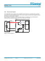
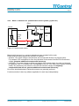
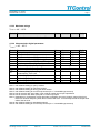
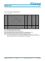
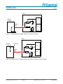
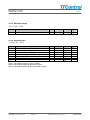
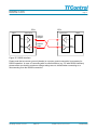
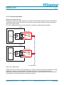
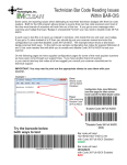
1
Product Name: TTC 50/60/90
Document Title: User Manual
Page 3
Contents
1
General Description .............................................................................................................. 6
1.1
1.2
1.3
1.4
1.5
2
Introduction ..................................................................................................................... 6
Interfaces and I/Os .......................................................................................................... 6
Safety and Certification ................................................................................................... 7
Advanced Programming Possibilities............................................................................... 7
Features.......................................................................................................................... 8
Pin connection .................................................................................................................... 10
2.1
2.2
Pin connection part 1..................................................................................................... 11
Pin connection part 2..................................................................................................... 13
3
Block Diagram..................................................................................................................... 14
4
Specification of Inputs and Outputs.................................................................................. 15
4.1
Positive power supply (BAT+......................................................................................... 15
4.1.1
Pinout: ................................................................................................................... 15
4.1.2
Functional description:........................................................................................... 15
4.1.3
Maximum ratings ................................................................................................... 16
4.1.4
Characteristics....................................................................................................... 17
4.1.5
Voltage Monitoring................................................................................................. 18
4.1.6
Wiring hints:........................................................................................................... 18
4.2
Negative power supply (BAT-)....................................................................................... 19
4.2.1
Pinout: ................................................................................................................... 19
4.2.2
Functional description:........................................................................................... 19
4.2.3
Maximum ratings ................................................................................................... 19
4.3
GND Analog Ground ..................................................................................................... 20
4.3.1
Pinout: ................................................................................................................... 20
4.3.2
Functional description:........................................................................................... 20
4.3.3
Maximum ratings ................................................................................................... 20
4.4
GND Digital Ground ...................................................................................................... 21
4.5
Pinout:........................................................................................................................... 21
4.5.1
Functional description:........................................................................................... 21
4.5.2
Maximum ratings ................................................................................................... 21
4.6
Ignition on switch input / Terminal 15 (Klemme15) ........................................................ 22
4.6.1
Pinout: ................................................................................................................... 22
4.6.2
Functional description:........................................................................................... 22
4.6.3
Maximum ratings ................................................................................................... 22
4.6.4
Characteristics....................................................................................................... 23
4.7
Variable Sensor supply ................................................................................................. 24
4.7.1
Pinout: ................................................................................................................... 24
4.7.2
Functional description:........................................................................................... 24
4.7.3
Maximum ratings ................................................................................................... 26
Last Change: 12/22/2009 11:43:00 AM
Author: WDI
File name: TTC50 user manual V2.0.doc
© TTControl GmbH
Product Name: TTC 50/60/90
Document Title: User Manual
Page 4
4.7.4
Characteristics....................................................................................................... 26
4.7.5
Sensor Supply Voltage Monitoring......................................................................... 27
4.8
Sensor Supply 5V......................................................................................................... 28
4.8.1
Pinout: ................................................................................................................... 28
4.8.2
Functional description:........................................................................................... 29
4.8.3
Maximum ratings ................................................................................................... 30
4.8.4
Characteristics....................................................................................................... 30
4.8.5
Supply Voltage Monitoring and Correction............................................................. 30
4.8.6
Supply Voltage Correction Formula ....................................................................... 31
4.9
Analog input 0..5V with SW- configuration.................................................................... 32
4.9.1
Pinout: ................................................................................................................... 32
4.9.2
Functional description:........................................................................................... 33
4.9.3
Mode 1: resistive sensors (i.e. NTC/PTC temperature sensors) ............................ 33
4.9.4
Mode 2: current loop active sensors ( 0..20mA)..................................................... 34
4.9.5
Mode 3: ratiometric for potentiometric sensors (pedals, joystick etc) .................... 35
4.9.6
Maximum ratings ................................................................................................... 36
4.9.7
Characteristics....................................................................................................... 36
4.10 Analog and digital input with range select 0..32V .......................................................... 37
4.10.1
Pinout: ................................................................................................................... 37
4.10.2
Functional description:........................................................................................... 38
4.10.3
Maximum ratings ................................................................................................... 40
4.10.4
Characteristics....................................................................................................... 40
4.10.5
Parameters for 5V ratiometric setting..................................................................... 40
4.10.6
Parameters for 5V absolute measurement setting ................................................. 41
4.10.7
Parameters for voltage range 10 .. 32V absolute measurement setting ................. 42
4.11 Board temperature sensor............................................................................................. 43
4.11.1
Pinout: ................................................................................................................... 43
4.11.2
Functional description:........................................................................................... 43
4.11.3
Characteristics....................................................................................................... 43
4.12 Digital input for frequency / timing measurement........................................................... 44
4.12.1
Pinout: ................................................................................................................... 44
4.12.2
Functional description:........................................................................................... 44
4.12.3
Maximum ratings ................................................................................................... 47
4.12.4
Characteristics digital parameters.......................................................................... 47
4.12.5
Characteristics analog parameters ........................................................................ 48
4.13 Digital inputs.................................................................................................................. 49
4.13.1
Pinout: ................................................................................................................... 49
4.13.2
Functional description:........................................................................................... 49
4.13.3
Maximum ratings ................................................................................................... 51
4.13.4
Characteristics....................................................................................................... 51
4.14 Power output 2A high side with PWM-control ................................................................ 52
4.14.1
Pinout: ................................................................................................................... 52
4.14.2
Functional description:........................................................................................... 53
4.14.3
Alternate functions:................................................................................................ 53
4.14.4
Maximum ratings ................................................................................................... 55
4.14.5
Characteristics of PWM high side output stage...................................................... 55
4.14.6
Characteristics of static (on/off) high side output stage .......................................... 55
Last Change: 12/22/2009 11:43:00 AM
Author: WDI
File name: TTC50 user manual V2.0.doc
© TTControl GmbH
Product Name: TTC 50/60/90
Document Title: User Manual
Page 5
4.14.7
Characteristics of frequency input (alternate function of output stage) ................... 56
4.14.8
Load Diagnostic Function High Side Output .......................................................... 57
4.14.9
Current Measurement Inputs ................................................................................. 58
4.14.10
Characteristics of Current Measurement Input................................................... 59
4.14.11
Alternate Function Low Side Output................................................................... 60
4.14.12
Example for switch off energy calculation for inductive loads: ............................ 61
4.14.13
Characteristics of Low Side Switch .................................................................... 62
4.14.14
Load Diagnostic Function .................................................................................. 63
4.14.15
Pinout: ............................................................................................................... 64
4.14.16
Functional description: ....................................................................................... 64
4.14.17
Example for switch off energy calculation for inductive loads: ............................ 65
4.14.18
Maximum ratings ............................................................................................... 66
4.14.19
Characteristics of output stage........................................................................... 66
4.14.20
Characteristics of analog input (alternate function of output stage) .................... 66
4.14.21
Load Diagnostic Function .................................................................................. 67
4.15 LIN interface.................................................................................................................. 68
4.15.1
Pinout: ................................................................................................................... 68
4.15.2
Functional description:........................................................................................... 68
4.15.3
Maximum ratings ................................................................................................... 70
4.15.4
Characteristics....................................................................................................... 70
4.16 RS232 interface ............................................................................................................ 71
4.16.1
Pinout: ................................................................................................................... 71
4.16.2
Functional description:........................................................................................... 71
4.16.3
Maximum ratings ................................................................................................... 73
4.16.4
Characteristics....................................................................................................... 73
4.17 CAN interface ISO 11898 .............................................................................................. 74
4.17.1
Pinout: ................................................................................................................... 74
4.17.2
Functional description:........................................................................................... 75
4.17.3
Maximum ratings ................................................................................................... 76
4.17.4
Characteristics....................................................................................................... 76
4.18 Mini Module / Current measurement.............................................................................. 77
4.18.1
Pinout: ................................................................................................................... 77
4.18.2
Functional description:........................................................................................... 78
4.18.3
Suitable functions for the Mini Module: .................................................................. 78
5
Application Notes ............................................................................................................... 79
5.1
5.2
Wiring Harness.............................................................................................................. 79
Load Distribution ........................................................................................................... 79
Last Change: 12/22/2009 11:43:00 AM
Author: WDI
File name: TTC50 user manual V2.0.doc
© TTControl GmbH
Product Name: TTC 50/60/90
Document Title: User Manual
1
1.1
Page 6
General Description
Introduction
TTC 50 is a family of programmable electronic control units for sensor/actuator management.
Many configurable I/Os allow its use with different sensor and actuator types. The control unit is
part of a complete and compatible product family and designed specifically for vehicles and
machines that function in rough environments and at extreme operating temperatures. Its robust
die-cast aluminum housing protects against electromagnetic disturbance and mechanical stress.
An 80 MHz Infineon XC2287 integrated microprocessor provides the necessary processing power.
The TTC 50 family consists of the following variants:
TTC 90: designed to fulfill safety requirements according to IEC 61508 SIL2 and ISO 13849
PL d
TTC 60
TTC 50
This document applies to all available variants TTC 50, TTC 60 and TTC 90. Throughout this
document, any reference to TTC 50 includes all family members TTC 50, TTC 60 and TTC 90.
Wherever specifications are not applicable for all variants, the differences are pointed out within
this document.
1.2
Interfaces and I/Os
All TTC 50 inputs and outputs are protected against electrical surges and short circuits. In addition,
internal safety measures allow the detection of open load, overload and short circuit conditions at
the outputs.
Proportional hydraulic components can be connected directly to the current controlled PWM
outputs.
The TTC 50 family is designed to support various analog and digital sensor types. Many SWconfigurable input options can be selected to adapt to different sensor types.
The widely used group of individually configurable analog inputs, well known from TTC 200, is also
supported by TTC 50. Additionally a group of analog inputs with voltage range from 0..5V to 0..32V
is provided that can be set to different voltage ranges by software for achieving best analog
accuracy and resolution.
The interfaces CAN, RS-232 and LIN are available for serial communication.
Last Change: 12/22/2009 11:43:00 AM
Author: WDI
File name: TTC50 user manual V2.0.doc
© TTControl GmbH
Product Name: TTC 50/60/90
Document Title: User Manual
1.3
Page 7
Safety and Certification
The variant TTC 90 was designed to comply with the IEC 61508 and ISO13849 international
standards. The ECU fulfils SIL 2 (Safety Integrity Level) and PL d requirements respectively.
The requirements in the Safety Manual shall be followed if the TTC 90 is used in safety-critical
applications.
1.4
Advanced Programming Possibilities
The unit may be programmed in C or CoDeSys. CoDeSys is one of the most common IEC 611313 programming systems that runs under Microsoft Windows®. Several editors are supported,
including the Instruction List Editor, the Sequential Function Chart Editor and the Function Block
Diagram Editor. CoDeSys produces native machine code for the main processor of TTC 50.
Last Change: 12/22/2009 11:43:00 AM
Author: WDI
File name: TTC50 user manual V2.0.doc
© TTControl GmbH
Product Name: TTC 50/60/90
Document Title: User Manual
1.5
Page 8
Features
System CPU
•
•
•
•
XC2287 (XE167 family), 80MHz, 768KB internal Flash, 64kB int. + 512kB ext. RAM; 16 kBit
EEPROM
Watchdog CPU - 68HC908
1 x RS232 (1200-115200Bd), 1 x LIN (1200Bd – 20000Bd)
2 x CAN, 125 to 1000 kbit/s
Power supply
•
•
•
•
•
•
•
Supply voltage: 9 to 32 V
CPU operates down to 4V battery supply during cranking
Load dump protection (max. steady state supply voltage 35V)
Low current consumption: 0.15 A at 9 V
1 x (8.5 or 10 or 15V / 50mA) sensor supply, voltage selected by software
2 x (5V / 50mA) sensor supply
Board temperature, sensor supply and battery monitoring
Inputs
•
•
•
•
8 x analog in 0 to 5 V or 0 to 20 mA or input for resistive sensors, 10 bit resolution,
configured by software (individual setting per input)
8 x analog / digital in range selectable, 10 bit resolution,
range settings 0 to 5V, 0 to 10V, 0 to 15V, 0 to 20V, 0 to 25V, 0 to 30V and 0 to 32V
with full 10 bit resolution, voltage selectable by software in groups of 4 inputs
4 x digital in (4 counter 10 to 10.000 Hz) supporting sensors with different output stages
(push pull, open collector, active high or low) as well as 7/14mA current loop (ABS-type)
sensors
8 x digital in
Outputs
•
•
•
•
8 x digital out 2.0 A, PWM, short-circuit and open load detection
current control loop for 4 PWM outputs
internal safety switch for all 2A PWM outputs
8 x digital out 4 A, short-circuit and open load detection
Last Change: 12/22/2009 11:43:00 AM
Author: WDI
File name: TTC50 user manual V2.0.doc
© TTControl GmbH
Product Name: TTC 50/60/90
Document Title: User Manual
Page 9
Specifications
•
•
•
•
•
•
Dimensions: 181 x 174 x 44 mm (with mounted connector)
Weight: 550 g
Ambient temperature: -40 °C to +85 °C
IP67 rated die-cast aluminum housing and 80 pin connector
Pressure adjusting with water barrier
Operating altitude: 0 to 4000 m
Last Change: 12/22/2009 11:43:00 AM
Author: WDI
File name: TTC50 user manual V2.0.doc
© TTControl GmbH
Product Name: TTC 50/60/90
Document Title: User Manual
2
Page 10
Pin connection
Figure 1: Connector front view
Last Change: 12/22/2009 11:43:00 AM
Author: WDI
File name: TTC50 user manual V2.0.doc
© TTControl GmbH
Product Name: TTC 50/60/90
Document Title: User Manual
2.1
Page 11
Pin connection part 1
Connector
Pin Number
P101
P102
P103
P104
P105
P106
P107
P108
P109
P110
P111
P112
P113
P114
P115
P116
P117
P118
P119
P120
P121
P122
P123
P124
P125
P126
P127
P128
P129
P130
P131
P132
P133
P134
P135
P136
P137
P138
P139
P140
Pin description
Battery (+) Supply Input for Internal Electronics
Battery (-) Supply Input
Power Output PWM 7 (2A)
Power Output PWM 5 (2A)
Power Output PWM 3 (2A)
Power Output PWM 1 (2A)
Current Measurement Input 3
Current Measurement Input 1
Current Measurement Input 3
Current Measurement Input 1
Analog Input 7 (0..32V)
Analog Input 5 (0..32V)
Analog Input 3 (0..32V)
Analog Input 1 (0..32V)
Power Output PWM 6 (2A)
Power Output PWM 4 (2A)
Power Output PWM 2 (2A)
Power Output PWM 0 (2A)
Current Measurement Input 2
Current Measurement Input 0
Current Measurement Input 2
Current Measurement Input 0
Analog Input 6 (0..32V)
Analog Input 4 (0..32V)
Analog Input 2 (0..32V)
Analog Input 0 (0..32V)
Battery (+) Supply Input for Power Stages
Battery (+) Supply Input for Power Stages
Power Output 7 (4A)
Power Output 5 (4A)
Power Output 3 (4A)
Power Output 1 (4A)
Analog Ground
Analog Ground
Sensor Supply Output 1 (5V)
Sensor Supply Output 0 (5V)
Analog Input 7 (0..5V)
Analog Input 5 (0..5V)
Analog Input 3 (0..5V)
Analog Input 1 (0..5V)
Last Change: 12/22/2009 11:43:00 AM
Author: WDI
File name: TTC50 user manual V2.0.doc
© TTControl GmbH
Product Name: TTC 50/60/90
Document Title: User Manual
P141
P142
P143
P144
P145
P146
P147
P148
P149
P150
P151
P152
Page 12
Power Output 6 (4A)
Power Output 4 (4A)
Power Output 2 (4A)
Power Output 0 (4A)
Analog Ground
Analog Ground
Sensor Supply Output 1 (5V)
Sensor Supply Output 0 (5V)
Analog Input 6 (0..5V)
Analog Input 4 (0..5V)
Analog Input 2 (0..5V)
Analog Input 0 (0..5V)
Last Change: 12/22/2009 11:43:00 AM
Author: WDI
File name: TTC50 user manual V2.0.doc
© TTControl GmbH
Product Name: TTC 50/60/90
Document Title: User Manual
2.2
Page 13
Pin connection part 2
Connector
Pin Number
P253
P254
P255
P256
P257
P258
P259
P260
P261
P262
P263
P264
P265
P266
P267
P268
P269
P270
P271
P272
P273
P274
P275
P276
P277
P278
P279
P280
Pin description
Digital Input 7
Digital Input 5
Digital Input 3
Digital Input 1
RS232 Serial Interface Output (TX)
Termination for CAN Interface 1 – High Line
CAN Interface 1 – Low Line
Digital Input 6
Digital Input 4
Digital Input 2
Digital Input 0
RS232 Serial Interface Input (RX)
CAN Interface 1 – High Line
Termination for CAN Interface 1 – Low Line
Digital Timer Input 3
Digital Timer Input 1
Sensor Supply Output (Variable)
Digital Ground
Terminal 15 Input
Termination for CAN Interface 0 – High Line
CAN Interface 0 – Low Line
Digital Timer Input 2
Digital Timer Input 0
Digital Ground
Digital Ground
LIN Bidirectional Signal Line
CAN Interface 0 – High Line
Termination for CAN Interface 0 – Low Line
Last Change: 12/22/2009 11:43:00 AM
Author: WDI
File name: TTC50 user manual V2.0.doc
© TTControl GmbH
Product Name: TTC 50/60/90
Document Title: User Manual
3
Page 14
Block Diagram
B+
KL15
+5V
+3V
main +
sensor
powersupply
B+
Safety switch driver
Reverse pol.protection
WD-CPU
68HC908GZ60
RES
var. sensor
supply
SPI
8*HS-switch
2A PWM
Enable
output
buffer
+
input
circuit
for
8*
PWM status
out
detection
EEPROM
SPI
8*ADC 0..32V
lowpassfilter
+
configur.
Network
+
MUX
+Ub
Board
temp.
8*
PWM
in
&
MUX0..2
2 * ADC
AN1-4..5
8*ADC 0..5V
lowpassfilter
+
range
configur.
+
MUX
Enable
B+
&
&
shift
register
(output
buffer)
+
input
circuit
+MUX
for
analog
status
detection
SPI
SPI
CPU
XC2287
16 * ADC
AN0-00..15
4*dynamic dig
input
lowpassfilter
+
configur.
network
SPI
MUX0..2
1 * ADC
AN1-7
1*ADC
AN1-6
4*PWM in
4*ADC
AN1-0..3
8*static dig input
SW-configurable
8*HS-switch
4A
amplifier
+
MUX
current
feedback
SPI
lowpassfilter
+
configur.
Network
RS232 Transceiver
RS232
8 * GPIO
LIN Transceiver
LIN
Adress/data
Bus
optional
minimodule
RAM
256k*16
CY7C1041CV3
CAN Transceiver
2*CAN
Figure 2: Block diagram
Last Change: 12/22/2009 11:43:00 AM
Author: WDI
File name: TTC50 user manual V2.0.doc
© TTControl GmbH
Product Name: TTC 50/60/90
Document Title: User Manual
4
Page 15
Specification of Inputs and Outputs
4.1
4.1.1
Positive power supply (BAT+
Pinout:
141 142 143 144 145 146 147 148 149 150 151 152
127
128
129 130 131 132 133 134 135 136 137 138 139 140
267
115 116 117 118 119 120 121 122 123 124 125 126
101
260
102
103 104 105 106 107 108 109 110 111 112 113 114
Connector Pin Number
P101
P127
P128
4.1.2
274
253
Function
Battery (+) Supply Input for Internal Electronics
Battery (+) Supply Input for Power Stages
Battery (+) Supply Input for Power Stages
Functional description:
Supply pins for positive supply.
One power pin to be used for supplying the internal electronics.
Two power pins to be used in parallel with 2.5mm² wires for total supply current of up to 30A.
For operation at least pin 101 and one of the pins 127 or 128 have to be connected. If the total
load current of the power stages exceeds 17A both pins for power stage supply have to be used.
Nominal supply voltage for full operation is 9 .. 32V, including both supply voltage ranges for 12
and 24V battery operation. In this voltage range all I/Os work according to the user manual. For the
Variable Senor Supply there is a different supply voltage spec. Transients exceeding this voltage
range are suppressed up to the non-destructive limits found in the maximum ratings.
For 12V systems there is an option for operation during cranking. The CPU is working down to 4V
battery supply (voltage drop until the starter motor makes its first turns, described in IS6736 Part1
for 12V systems). For safety reasons this function is limited to 1 second.
Last Change: 12/22/2009 11:43:00 AM
Author: WDI
File name: TTC50 user manual V2.0.doc
© TTControl GmbH
Product Name: TTC 50/60/90
Document Title: User Manual
4.1.3
Page 16
Maximum ratings
Tambient = -40° .. 85°C
Ratings for Pin 101, 127 and 128
Symbol Parameter
Uin-max permanent none-destructive supply voltage
Uin-lim
peak none-destructive supply clamping
voltage
Iin-lim
peak none-destructive supply clamping
current
Td
Load dump protection according to
ISO7636-2, Pulse 5, Level IV
(superimposed 174V, Ri=2Ω)
Note min
-32
1
-40
max
32
45
Units
V
V
1
+100
A
350
ms
30
A
17
A
1
-10
Ratings for Pin 127 and 128 only
Iin-max_
Iin-max
Permanent input current (Pins 127 and 128
in parallel with symmetrical wire connection)
Permanent input current per pin
Note1: control unit is protected by transient suppressor diode, specified is clamp voltage, current and
duration of voltage transient
Last Change: 12/22/2009 11:43:00 AM
Author: WDI
File name: TTC50 user manual V2.0.doc
© TTControl GmbH
Product Name: TTC 50/60/90
Document Title: User Manual
4.1.4
Page 17
Characteristics
Tambient = -40° .. 85°C
Symbol
Cin
Uin
Uin
Tcrank
Iin-idle
Iin-idle
Iin-idle
Iin-STBY
Iin-STBY
Parameter
Capacitance load at input
Supply voltage for full operation
Supply voltage for CPU operation
Max. duration low battery voltage below 9V
without CPU reset
Supply current of unit without load
Supply current of unit without load
Supply current of unit without load
Standby supply current (KL15 off)
Standby supply current (KL15 off)
Note min
9
4
1
2
3
4
5
max
500
32
32
1000
0.15
0.11
0.08
0.5
1.0
Units
μF
V
V
ms
A
A
A
mA
mA
Note 1:
Note 2:
Note 3:
Note 4:
at UBat = 9V
at UBat = 12V
at UBat = 24V
at UBat = 27V / TECU = Tambient = -40°.. 85°C
These are worst case operating conditions during standby.
Note 5: at UBat = 32V / TECU = 85°.. 125°C
These are operating conditions during or immediately after switching to standby:
The battery voltage is higher than the maximum output voltage of the battery.
The ECU was internally heated up to an over temperature of 40K. After some minutes the ECU cools
down and the internal temperature is equal to the ambient temperature (max. 85°C).
Last Change: 12/22/2009 11:43:00 AM
Author: WDI
File name: TTC50 user manual V2.0.doc
© TTControl GmbH
Product Name: TTC 50/60/90
Document Title: User Manual
4.1.5
Page 18
Voltage Monitoring
The battery voltage is connected to an ADC-input. Battery voltage measurement can be used for
voltage compensation for PWM-controlled loads or for diagnostic purpose.
The input voltage is attenuated to a factor of 0.14826 (nom, or divided by 6.745) thus allowing
voltage measurement up to 32.76V (nom.)
Tambient = -40° .. 85°C
Symbol Parameter
VOut
Scale factor (nom)
fg_LP
Nominal battery supply range that can be
measured
VTol-M
ADC voltage tolerance (of reading)
VTol-0
ADC voltage tolerance (offset)
fg_LP
Cut off frequency of 1st order low pass filter
Note min
1
2
9
3
3
4
-4
-0.1
30
max
0.12466
32.7
+4
+0.1
50
Units
V
%
V
Hz
Note 1: 12V input voltage will be attenuated to 1.496 on the ADC input
Note 2: Low limit is given by minimum supply voltage of the ECU, high limit is full scale limit of ADC
Note 3: Total error is the sum of proportional error and zero reading error:
TUE = ± VTol −M *U Bat ± VTol −0
st
Note 4: A low pass filter (1 order) is provided to remove glitches on the battery voltage from the ADC
input
4.1.6
Wiring hints:
The ECU is limited to a total load current of 30A (maximum) for the power stages, connected to
pins 127 and 128. When all loads are tied towards ground, the load current will be also carried by
these supply pins. Each contact pin is thermally limited to 17A (maximum). 2 supply pins work in
parallel for the power stages supply. So the system designer must be careful with the cable
harness design to guarantee evenly distribution of supply current on all three pins.
Example: It is not ok to use one cable with a length of two meters and large diameter for a
connection between a fuse box and the ECU and crimp it to 2 piggy tails with small diameter in the
connector area. Small differences in the contact pressure can lead to a big imbalance. In worst
case condition 1 contact carries most of the current load and is overloaded at maximum current. It
is better to use 2 wires with the same total cross sectional area than this one thick cable. All wires
must have exactly the same length and diameter. In this case an evenly distribution of current will
be the case even with slightly different contact resistance.
Last Change: 12/22/2009 11:43:00 AM
Author: WDI
File name: TTC50 user manual V2.0.doc
© TTControl GmbH
Product Name: TTC 50/60/90
Document Title: User Manual
4.2
4.2.1
Page 19
Negative power supply (BAT-)
Pinout:
141 142 143 144 145 146 147 148 149 150 151 152
127
128
129 130 131 132 133 134 135 136 137 138 139 140
267
115 116 117 118 119 120 121 122 123 124 125 126
101
Connector Pin Number
P102
253
Function
Battery (-) Supply Input
Functional description:
Supply pin for negative supply.
Power pin to be used with 1.5mm² or 2.5mm² wires for total return current of 17A.
4.2.3
260
102
103 104 105 106 107 108 109 110 111 112 113 114
4.2.2
274
Maximum ratings
Tambient = -40° .. 85°C
Symbol Parameter
Iin-max
Permanent supply current
Note min
1
Max
17
Units
A
Note 1: GND supply current in excess of 1A is produced by inductive loads during free wheeling.
This is not a continues current but a pulsed current with a duty cycle. For high current values the
duty cycle is smaller than 50%. Even with all PWM outputs on at rated current and 50% duty cycle
the RMS value will be less than 10A. For calculation of voltage drops please observe the direction of
the current. It is negative that means the voltage drop is negative, the over all supply voltage of the
TTC50 is increased through this voltage drop.
Last Change: 12/22/2009 11:43:00 AM
Author: WDI
File name: TTC50 user manual V2.0.doc
© TTControl GmbH
Product Name: TTC 50/60/90
Document Title: User Manual
4.3
4.3.1
Page 20
GND Analog Ground
Pinout:
141 142 143 144 145 146 147 148 149 150 151 152
127
128
129 130 131 132 133 134 135 136 137 138 139 140
267
115 116 117 118 119 120 121 122 123 124 125 126
101
Connector Pin Number
P133
P134
P145
P146
253
Function
Analog Ground
Analog Ground
Analog Ground
Analog Ground
Functional description:
Supply pins for analog sensor GND connection.
4.3.3
260
102
103 104 105 106 107 108 109 110 111 112 113 114
4.3.2
274
Maximum ratings
Tambient = -40° .. 85°C
Symbol Parameter
Iout-max
Permanent current per pin
Last Change: 12/22/2009 11:43:00 AM
Author: WDI
Note min
max
2
File name: TTC50 user manual V2.0.doc
Units
A
© TTControl GmbH
Product Name: TTC 50/60/90
Document Title: User Manual
Page 21
4.4
GND Digital Ground
4.5
Pinout:
152
140
126
114
274 275 276 277 278 279 280
267 268 269 270 271 272 273
260 261 262 263 264 265 266
253 254 255 256 257 258 259
Connector Pin Number
P270
P276
P277
4.5.1
Function
Digital Ground
Digital Ground
Digital Ground
Functional description:
Supply pins for digital sensor GND connection or GND connections for switches.
Can be used as sensor supply GND or for light loads..
4.5.2
Maximum ratings
Tambient = -40° .. 85°C
Symbol Parameter
Iout-max
Permanent current per pin
Last Change: 12/22/2009 11:43:00 AM
Author: WDI
Note min
max
2
File name: TTC50 user manual V2.0.doc
Units
A
© TTControl GmbH
Product Name: TTC 50/60/90
Document Title: User Manual
4.6
4.6.1
Ignition on switch input / Terminal 15 (Klemme15)
Pinout:
152
274 275 276 277 278 279 280
267 268 269 270 271 272 273
140
126
260 261 262 263 264 265 266
253 254 255 256 257 258 259
114
Connector Pin Number
P271
4.6.2
Page 22
Function
Terminal 15 Input
Functional description:
Only used for permanent supplied systems. When switched to positive supply, this input gives the
command to power up the ECU. When switched off, the ECU performs activates its keep-alive
functionality and switches off by software.
For systems with main power switch (not permanent supplied) this pin must be tied to the BAT+
pins (101, 127, 128).
This input can also be monitored via a digital input of the CPU.
4.6.3
Maximum ratings
Tambint = -40° .. 85°C
Symbol
Vin
Vin
Vin
Parameter
Permanent (DC) input voltage
Transient peak input voltage 500ms
Transient peak input voltage 1ms
Last Change: 12/22/2009 11:43:00 AM
Author: WDI
Note min
-32
-50
-100
max
32
50
100
File name: TTC50 user manual V2.0.doc
Units
V
V
V
© TTControl GmbH
Product Name: TTC 50/60/90
Document Title: User Manual
4.6.4
Page 23
Characteristics
Tambient = -40° .. 85°C
Symbol
Cin
Rpu
VIL
VIH
τin
Parameter
Pin input capacitance
Pulldown resistor to GND
Input voltage for low level
Input voltage for high level
Input low pass filter
Last Change: 12/22/2009 11:43:00 AM
Author: WDI
Note min
40
9.85
-1
3.8
0.4
max
60
10.15
1.8
UBat
0.6
File name: TTC50 user manual V2.0.doc
Units
nF
kΩ
V
V
ms
© TTControl GmbH
Product Name: TTC 50/60/90
Document Title: User Manual
4.7
Page 24
Variable Sensor supply
4.7.1
152
140
126
114
Pinout:
274 275 276 277 278 279 280
267 268 269 270 271 272 273
260 261 262 263 264 265 266
253 254 255 256 257 258 259
Connector Pin Number
P269
4.7.2
Function
Sensor Supply Output (Variable)
Functional description:
This sensor supply output is provided for sensors that operate at higher voltages than 5V.
Examples are analog or digital current loop sensors that do not withstand direct connection to
battery. In this case the sensor supply acts as voltage limiter.
The software can configure this output to one of the following nominal supply voltages:
8.5V
10.0V
14.5V
Last Change: 12/22/2009 11:43:00 AM
Author: WDI
File name: TTC50 user manual V2.0.doc
© TTControl GmbH
Product Name: TTC 50/60/90
Document Title: User Manual
Page 25
Typical sensors supplied with 14.5V are the current loop (ABS-type) speed sensors and analog
transducers /e.g. pressure sensors) with current output.
The actual output voltage is read back by the ADC-unit for monitoring purposes.
Sensor
Variable
Sensor
Supply
ECU
+8.5V
+10V
+14.5V
CPU
A/D
4 .. 20mA
Figure 3: Variable sensor supply used for analog current loop sensor (4..20mA)
Last Change: 12/22/2009 11:43:00 AM
Author: WDI
File name: TTC50 user manual V2.0.doc
© TTControl GmbH
Product Name: TTC 50/60/90
Document Title: User Manual
4.7.3
Page 26
Maximum ratings
Tambient = -40° .. 85°C
Symbol Parameter
Vin
Output voltage under overload conditions
(i.e. short circuit to supply voltages)
4.7.4
Note min
-1
max
32
Units
V
Note min
4
1
8
2
9.4
3
13.8
4
max
6
9.2
10.8
15.2
0.3
Units
μF
V
V
V
V
5
6
30
40
mA
mA
Characteristics
Tambient = -40° .. 85°C
Symbol
Cout
Vout
Vout
Vout
VBat-min
Iload
Iload
Parameter
Pin output capacitance
Output voltage, at Iload and over VBat-min
Output voltage, at Iload and over VBat-min
Output voltage, at Iload and over VBat-min
Minimum voltage drop to allow nominal
output voltage
Load current
Load current 14.5V
0
0
Note 1:
Note 2:
Note 3:
Note 4:
Output setting to 8.5V
Output setting to 10V
Output setting to 14.5V
This output is provided by a linear voltage regulator.
The battery voltage must be at lest 0.3V higher than the regulated output voltage.
Note 5: For all voltage settings and at highest supply voltage.
Note 6: For voltage setting to 14.5V and at highest supply voltage.
Last Change: 12/22/2009 11:43:00 AM
Author: WDI
File name: TTC50 user manual V2.0.doc
© TTControl GmbH
Product Name: TTC 50/60/90
Document Title: User Manual
4.7.5
Page 27
Sensor Supply Voltage Monitoring
Tambient = -40° .. 85°C
Symbol Parameter
Read back attenuation factor
αUGEB
Note min
1
0.3140
max
0.3236
Units
VUG-SRC Read back values normal operation
8.5V setting
VUG-SRC Read back values normal operation
10.0V setting
VUG-SRC Read back values normal operation
14.5V setting
2
2.462
3.037
V
2
2.893
3.564
V
2
4.247
4.990
V
Note 1: Supply is read back to allow ratiometric measurement. In order to guarantee that the read back input
is always in the ADC operating range, an attenuating voltage divider (nom *0.3188) is inserted.
Note 2: Due to tolerances in the actual supply voltage of main- and sensor-supply the read back value may
vary in the range specified.
Values outside this window indicate voltage failure in the sensor supply (short circuit or overload)
and must set the sensor failure flag.
Last Change: 12/22/2009 11:43:00 AM
Author: WDI
File name: TTC50 user manual V2.0.doc
© TTControl GmbH
Product Name: TTC 50/60/90
Document Title: User Manual
4.8
4.8.1
Page 28
Sensor Supply 5V
Pinout:
141 142 143 144 145 146 147 148 149 150 151 152
127
128
129 130 131 132 133 134 135 136 137 138 139 140
274
267
115 116 117 118 119 120 121 122 123 124 125 126
101
260
102
103 104 105 106 107 108 109 110 111 112 113 114
Connector Pin Number
P136
P148
P135
P147
Last Change: 12/22/2009 11:43:00 AM
253
Function
Sensor Supply Output 0 (5V)
Sensor Supply Output 0 (5V)
Sensor Supply Output 1 (5V)
Sensor Supply Output 1 (5V)
Author: WDI
File name: TTC50 user manual V2.0.doc
© TTControl GmbH
Product Name: TTC 50/60/90
Document Title: User Manual
4.8.2
Page 29
Functional description:
Two independent sensor supplies are provided for 3-wire-sensors (i.e. potentiometers, pressure
sensors etc.). For fully redundant sensors with 2 sensor supply connections both supplies must be
connected to different sensor supplies.
Sensor Supply 1 is defined to be the redundant supply. For detecting short circuits between
redundant analog inputs the sensor supply can be switched off by SW.
ECU
Sensor
Sensor
Supply 5V
+5V
CPU
A/D
Figure 4: Sensor supply 5V
Last Change: 12/22/2009 11:43:00 AM
Author: WDI
File name: TTC50 user manual V2.0.doc
© TTControl GmbH
Product Name: TTC 50/60/90
Document Title: User Manual
4.8.3
Page 30
Maximum ratings
Tambient = -40° .. 85°C
Symbol Parameter
Vin
Output voltage under overload conditions
(i.e short circuit to supply voltages)
4.8.4
Note min
-1
max
32
Units
V
Note min
4
4.9
1
-25
0
max
6
5.1
+15
50
Units
μF
V
mV
mA
Characteristics
Tambient = -40° .. 85°C
Symbol
Cout
Vout
Vout
Iload
Parameter
Pin output capacitance
Output voltage, at Iload
Output voltage differential, at Iload
Load current
Note 1: This sensor supply is a tracking regulator to the internal 5V supply which is also the reference
voltage of the ADC unit.
4.8.5
Supply Voltage Monitoring and Correction
Tambient = -40° .. 85°C
Symbol
αUGEB
VUG-SRC
kREF
Parameter
Read back attenuation factor
Read back values normal operation
Reference correction value
Note min
1
0.9780
2
4.865
max
0.9789
4.910
4.8924
Units
V
V
Note 1: Supply is read back to allow ratiometric measurement. Due to tolerances the sensor supply might be
higher than the ADC reference thus exceeding the allowed voltage range. In order to guarantee that
the read back input is always in the ADC operating range, an attenuating voltage divider (nom
*0.9785) is inserted.
Note 2: When all parameters are nominal value the read back input (referred to ADC reference) will show
4.8924V. Due to tolerances in the actual supply voltage of main- and sensor-supply the read back
value may vary in the range specified.
Please note that this window will not affect the measurement accuracy when using the correction
formula below.
Values outside this window indicate voltage failure in the sensor supply (short circuit or overload)
and must set the sensor failure flag.
Last Change: 12/22/2009 11:43:00 AM
Author: WDI
File name: TTC50 user manual V2.0.doc
© TTControl GmbH
Product Name: TTC 50/60/90
Document Title: User Manual
4.8.6
Page 31
Supply Voltage Correction Formula
Correction formula for ratiometric measurement:
U IN −rat =
N ADC − ANx
∗ k REF
N ADC −UGEBy
[V]
N ADC −UGEBy
ADC value of sensor supply voltage
N ADC − ANx
ADC value of sensor input voltage
U IN −rat
Ratiometric equivalent input voltage
Result in volts calculated for a supply of exactly 5V.
Example: An input voltage with 20% of sensor supply will show a result of
1.0V regardless of actual sensor supply voltage (within the normal operating
range).
The software drivers for ADC 0..5V and ADC 0 .. 32V inputs use this calculation formula for the
output result when set to ratiometric input mode.
Last Change: 12/22/2009 11:43:00 AM
Author: WDI
File name: TTC50 user manual V2.0.doc
© TTControl GmbH
Product Name: TTC 50/60/90
Document Title: User Manual
4.9
4.9.1
Page 32
Analog input 0..5V with SW- configuration
Pinout:
141 142 143 144 145 146 147 148 149 150 151 152
127
128
274
129 130 131 132 133 134 135 136 137 138 139 140
267
115 116 117 118 119 120 121 122 123 124 125 126
101
260
102
103 104 105 106 107 108 109 110 111 112 113 114
Connector Pin Number
P152
P140
P151
P139
P150
P138
P149
P137
Last Change: 12/22/2009 11:43:00 AM
Function 1
Analog Input
0 .. 5V
Analog Input
0 .. 5V
Analog Input
0 .. 5V
Analog Input
0 .. 5V
Analog Input
0 .. 5V
Analog Input
0 .. 5V
Analog Input
0 .. 5V
Analog Input
0 .. 5V
Author: WDI
0
1
2
3
4
5
6
7
Function 2
Analog Input
0 .. 20mA
Analog Input
0 .. 20mA
Analog Input
0 .. 20mA
Analog Input
0 .. 20mA
Analog Input
0 .. 20mA
Analog Input
0 .. 20mA
Analog Input
0 .. 20mA
Analog Input
0 .. 20mA
0
1
2
3
4
5
6
7
Function 3
Analog Input
0 .. 100kΩ
Analog Input
0 .. 100kΩ
Analog Input
0 .. 100kΩ
Analog Input
0 .. 100kΩ
Analog Input
0 .. 100kΩ
Analog Input
0 .. 100kΩ
Analog Input
0 .. 100kΩ
Analog Input
0 .. 100kΩ
File name: TTC50 user manual V2.0.doc
253
0
1
2
3
4
5
6
7
© TTControl GmbH
Product Name: TTC 50/60/90
Document Title: User Manual
4.9.2
Page 33
Functional description:
This kind of input can be set to 3 different operation modes individually by SW.
Fits to different types of sensors:
4.9.3
Mode 1: resistive sensors (i.e. NTC/PTC temperature sensors)
ECU
Sensor
+5V
A/D
Analog
Input (0..5V)
Figure 5: Resistive sensor
This mode may also be used as switch input with switches connected to ground.
The use of switches to BAT+ is not allowed.
ECU
Switch
+5V
A/D
Analog
Input (0..5V)
Figure 6: Switch input (only for switches to ground)
Last Change: 12/22/2009 11:43:00 AM
Author: WDI
File name: TTC50 user manual V2.0.doc
© TTControl GmbH
Product Name: TTC 50/60/90
Document Title: User Manual
4.9.4
Page 34
Mode 2: current loop active sensors ( 0..20mA)
ECU
+8.5V
+10V
+14.5V
Sensor
CPU
Analog
Input
(0..5V)
A/D
4 .. 20mA
Figure 7: Current loop active sensor
Last Change: 12/22/2009 11:43:00 AM
Author: WDI
File name: TTC50 user manual V2.0.doc
© TTControl GmbH
Product Name: TTC 50/60/90
Document Title: User Manual
4.9.5
Page 35
Mode 3: ratiometric for potentiometric sensors (pedals, joystick etc)
ECU
Sensor
+5V
Analog
Input
(0..5V)
CPU
A/D
Figure 8: Potentiometric sensor
Most physical sensors (e.g. pressure transducers) are operated in this mode.
Please note that many sensors are offered in 2 variants:
- absolute: The output voltage is a fixed value and corresponds directly to a physical value.
For example 2.5V corresponds to 1bar. Any tolerance in the sensor’s and the ECU’S reference
voltage generates additional measurement inaccuracy.
- ratiometric: The output voltage is a fixed percentage of the sensor supply, the ratio corresponds
to a physical value. For example 50% corresponds to 1bar (or 2.5V if the sensor supply is exactly
5.00V). Any tolerance in the sensor’s or the ECU’S reference voltage is completely
compensated and will not generate additional measurement inaccuracy.
Due to the described behavior ratiometric sensors are generally preferred.
Function selection is done by software application for each input independently
Last Change: 12/22/2009 11:43:00 AM
Author: WDI
File name: TTC50 user manual V2.0.doc
© TTControl GmbH
Product Name: TTC 50/60/90
Document Title: User Manual
4.9.6
Page 36
Maximum ratings
Tambient = -40° .. 85°C
Symbol Parameter
Vin
Input voltage under overload conditions
Note min
1
-1
max
32
Units
V
Note 1: due to thermal reasons only one of the 8 inputs may be shorted to 32V at the same time.
A connection to any supply voltage higher than 5V is not allowed for normal operation.
4.9.7
Characteristics
Tambient = -40° .. 85°C
Symbol
Cin
Rin
Rpu
Rin
Rpd
Rin
τin
VCC
VIn
VTol
LSB
Parameter
Pin input capacitance
Input resistance to VCC
Reference resistor
Input resistance to GND
Reference resistor
Input resistance to GND
Input low pass filter
ADC reference voltage
ADC input voltage range
ADC voltage tolerance
Nominal value of 1 LSB (Full scale / 1024)
Note min
4
1
1202
1
1202
2
217
2
217
3
99.7
0.7
4.85
0
4
-25
max
6
1250
1238
230
223
102.7
1.3
5.15
VCC
+25
4.88
Units
nF
Ω
Ω
Ω
Ω
kΩ
ms
V
V
mV
mV
Note 1: configuration mode 1 (resistive sensor)
Note 2: configuration mode 2 (current loop sensor)
Note 3: configuration mode 3 (potentiometric sensor)
Note 4: VCC is the reference voltage of the ADC. Therefore measurement is referred to VCC . For total
tolerance including sensor in mode 1 (ratiometric measuring) or mode 3 when using the built in
sensor supply (by reading back the offset) VCC is not a parameter in error calculation.
Last Change: 12/22/2009 11:43:00 AM
Author: WDI
File name: TTC50 user manual V2.0.doc
© TTControl GmbH
Product Name: TTC 50/60/90
Document Title: User Manual
Page 37
4.10 Analog and digital input with range select 0..32V
Note: The analog inputs with range select are only available on TTC 60 and TTC 90, not on TTC
50.
4.10.1 Pinout:
141 142 143 144 145 146 147 148 149 150 151 152
127
128
129 130 131 132 133 134 135 136 137 138 139 140
267
115 116 117 118 119 120 121 122 123 124 125 126
101
274
260
102
103 104 105 106 107 108 109 110 111 112 113 114
Connector Pin Number
P126
P114
P125
P113
P124
P112
P123
P111
Last Change: 12/22/2009 11:43:00 AM
Function
Analog input (from 0..5 up to 0..32V)
Analog input (from 0..5 up to 0..32V)
Analog input (from 0..5 up to 0..32V)
Analog input (from 0..5 up to 0..32V)
Analog input (from 0..5 up to 0..32V)
Analog input (from 0..5 up to 0..32V)
Analog input (from 0..5 up to 0..32V)
Analog input (from 0..5 up to 0..32V)
Author: WDI
253
0
1
2
3
4
5
6
7
File name: TTC50 user manual V2.0.doc
© TTControl GmbH
Product Name: TTC 50/60/90
Document Title: User Manual
Page 38
4.10.2 Functional description:
Eight multi purpose analog input with 10 bit resolution are provided, divided into 2 input groups,
each with 4 pins.
The inputs are intended to be used with:
analog sensors 0..5V ratiometric or with absolute reference.
analog sensors with higher output voltage than 5V and absolute reference.
each group can be adapted to different full scale voltages up to 0..32V per SW
standard settings: 0..5V, 0..10V, 0..15V, 0..20V, 0..25V, 0..30V, 0..32V
full 10bit resolution for any range.
digital switch input with switches that may be connected either to ground or to battery
supply.
The ADC values can be referenced either to internal supply or sensor supply (ratiometric mode) or
to a internal accurate reference voltage (absolute reference) for each channel individually.
analog
Sensor
ECU
Sensor
Supply
CPU
Analog
Input
(0..32V)
A/D
Figure 9: Analog sensor input 0..32V
Last Change: 12/22/2009 11:43:00 AM
Author: WDI
File name: TTC50 user manual V2.0.doc
© TTControl GmbH
Product Name: TTC 50/60/90
Document Title: User Manual
Page 39
ECU
Switch
to supply
5/12/24V
CPU
Analog
Input
(0..32V)
A/D
Figure 10: Switch to Sensor Supply or BAT+ connected to sensor input 0..32V
ECU
Switch
to GND
CPU
Analog
Input
(0..32V)
A/D
Figure 11: Switch to GND connected to sensor input 0..32V
Last Change: 12/22/2009 11:43:00 AM
Author: WDI
File name: TTC50 user manual V2.0.doc
© TTControl GmbH
Product Name: TTC 50/60/90
Document Title: User Manual
Page 40
4.10.3 Maximum ratings
Tambient = -40° .. 85°C
Symbol Parameter
Vin
Input voltage under overload conditions
Note min
-1
max
32
Units
V
4.10.4 Characteristics
Tambient = -40° .. 85°C
4.10.5 Parameters for 5V ratiometric setting
For 3 pin sensors that are supplied with one of the TTC50’s sensor supplies and use this supply as
reference for the output signal. Output voltages of these sensors are typically described as
percentage of the supply voltage.
The software compares the input voltage with the actual sensor supply voltage. The calculated
output value is a portion of the supply voltage. Any deviation of either sensor supply or internal
supply voltage from the typical value (in the operating range) will not influence the output value.
Therefore ratiometric measurement will be in most cases more accurate compared to
measurement where sensor and ECU uses each there built in references. In this case the sum of
the tolerance of both references has to be added to the ADC error.
Symbol
Cin
Rin
Rin
τin
VCC
VIn
VTol-0
VTol-M
Parameter
Pin input capacitance
Input resistance to VCC
Input resistance to GND
Input low pass filter
ADC reference voltage VCC
ADC input voltage range
ADC voltage tolerance (zero)
ADC voltage tolerance (full scale)
Note min
4
1
9.85
1
9.85
40
2
4.85
0
3
-25
3
-50
max
6
10.25
10.25
55
5.15
VCC
+25
+25
Units
nF
kΩ
kΩ
ms
V
V
mV
mV
Note 1: Depending on SW-setting.
Note 2: VCC is the reference voltage of the ADC. Therefore measurement is referred to VCC .
Note 3: VCC is the reference voltage of the ADC. Therefore measurement is referred to VCC . For total
tolerance including sensor with ratiometric measuring mode using the built in sensor supply (by
reading back the offset) VCC is not a parameter in error calculation.
Last Change: 12/22/2009 11:43:00 AM
Author: WDI
File name: TTC50 user manual V2.0.doc
© TTControl GmbH
Product Name: TTC 50/60/90
Document Title: User Manual
Page 41
4.10.6 Parameters for 5V absolute measurement setting
This setting is for sensors that work only with an internal reference. For this reason the TTC50 can
make use of an internal precision reference with better accuracy than the ADC reference.
Symbol
Cin
Rin
Rin
τin
VCC
VIn
VTol-0
VTol-M
VTol-R
LSB
Parameter
Pin input capacitance
Input resistance to VCC
Input resistance to GND
Input low pass filter
ADC reference voltage VCC
ADC input voltage range
ADC voltage tolerance (zero)
ADC voltage tolerance (full scale)
ADC voltage tolerance (full scale)
Nominal value of 1 LSB (Full scale / 1024)
Note min
4
1
9.85
1
9.85
40
2
4.85
0
3
-25
3
-150
3
-3.0
max
6
10.25
10.25
55
5.15
4.85
+25
+125
+2.5
4.88
Units
nF
kΩ
kΩ
ms
V
V
mV
mV
%
mV
Note 1: Depending on SW-setting.
Note 2: VCC is the reference voltage of the ADC. Therefore measurement is referred to VCC .
Note 3: VCC is the reference voltage of the ADC. Therefore measurement is referred to VCC . For nonratiometric sensors the ADC reference voltage tolerance is included in this oval all error calculation.
Last Change: 12/22/2009 11:43:00 AM
Author: WDI
File name: TTC50 user manual V2.0.doc
© TTControl GmbH
Product Name: TTC 50/60/90
Document Title: User Manual
Page 42
4.10.7 Parameters for voltage range 10 .. 32V absolute measurement setting
This setting is for sensors that work only with an internal reference. For this reason the TTC 50 can
make use of an internal precision reference with better accuracy than the ADC reference.
Symbol
Cin
Rin
Rin
τin
VCC
Parameter
Pin input capacitance
Input resistance to VCC
Input resistance to GND
Input low pass filter
ADC reference voltage VCC
Note min
4
1
9.85
1
9.85
7
2
4.85
max
6
10.25
10.25
25
5.15
Units
nF
kΩ
kΩ
ms
V
10V setting for range selection
VIn
VTol-R
VTol-R
LSB
ADC input voltage range
ADC voltage tolerance (zero)
ADC voltage tolerance (full scale)
Nominal value of 1 LSB (Full scale / 1024)
0
-3
-4.0
10
+3
+4.0
9.765
V
LSB
%
mV
0
-3
-4.0
15
+3
+4.0
14.65
V
LSB
%
mV
0
-3
-4.0
20
+3
+4.0
19.5
V
LSB
%
mV
0
-2
-4.0
25
+2
+4.0
24.4
V
LSB
%
mV
0
-2
-4.0
30
+2
+4.0
29.3
V
LSB
%
mV
0
-2
-4.0
32
+2
+4.0
32.2
V
LSB
%
mV
15V setting for range selection
VIn
VTol-R
VTol-R
LSB
ADC input voltage range
ADC voltage tolerance (zero)
ADC voltage tolerance (full scale)
Nominal value of 1 LSB (Full scale / 1024)
20V setting for range selection
VIn
VTol-R
VTol-R
LSB
ADC input voltage range
ADC voltage tolerance (zero)
ADC voltage tolerance (full scale)
Nominal value of 1 LSB (Full scale / 1024)
25V setting for range selection
VIn
VTol-R
VTol-R
LSB
ADC input voltage range
ADC voltage tolerance (zero)
ADC voltage tolerance (full scale)
Nominal value of 1 LSB (Full scale / 1024)
30V setting for range selection
VIn
VTol-R
VTol-R
LSB
ADC input voltage range
ADC voltage tolerance (zero)
ADC voltage tolerance (full scale)
Nominal value of 1 LSB (Full scale / 1024)
32V setting for range selection
VIn
VTol-R
VTol-R
LSB
ADC input voltage range
ADC voltage tolerance (zero)
ADC voltage tolerance (full scale)
Nominal value of 1 LSB (Full scale / 1024)
3
Note 1: Depending on SW-setting.
Note 2: VCC is the reference voltage of the ADC. Therefore measurement is referred to VCC .
Note 3: nominal full scale value is 33.65V. This is higher than the max. permanent input voltage with 32V.
Last Change: 12/22/2009 11:43:00 AM
Author: WDI
File name: TTC50 user manual V2.0.doc
© TTControl GmbH
Product Name: TTC 50/60/90
Document Title: User Manual
Page 43
4.11 Board temperature sensor
4.11.1 Pinout:
Connector Pin Number
No connector pin,
internal sensor.
Function
Board Temperature Sensor
4.11.2 Functional description:
On board PTC-type temperature sensor. Allows monitoring ECU internal temperature for
diagnostic purpose and safety features (strategy to bring machine to safe state and switch off
loads in case of over temperature detected)
4.11.3 Characteristics
Tambient = -40° .. 85°C
Symbol
Top
αADC
αADC
αADC
VTol-m
Parameter
measure temperature range
Resolution per K at –40°C
Resolution per K at +20°C
Resolution per K at +130°C
Temperature tolerance at 120°C
Note min
-40
1
1
1
3
-6
max
+130
1.54
1.68
1.12
+6
Units
°C
LSB
LSB
LSB
K
Note 1: due to characteristic of the sensor the resolution (change of ADC value per degree K) will depend on
actual temperature value. Characteristic values are listed for 3 different temperatures.
Last Change: 12/22/2009 11:43:00 AM
Author: WDI
File name: TTC50 user manual V2.0.doc
© TTControl GmbH
Product Name: TTC 50/60/90
Document Title: User Manual
4.12
Page 44
Digital input for frequency / timing measurement
4.12.1 Pinout:
152
140
126
114
274 275 276 277 278 279 280
267 268 269 270 271 272 273
260 261 262 263 264 265 266
253 254 255 256 257 258 259
Connector Pin Number
P275
P268
P274
P267
Function
Digital Timer Input
Digital Timer Input
Digital Timer Input
Digital Timer Input
0
1
2
3
4.12.2 Functional description:
Four digital inputs with timer function are provided to process input signals like frequency
(rotational speed), pulse count and quadrature decoding (incremental length measurement), PWM
etc.
The inputs can be configured with different pull-up / pull-down resistors and input thresholds by
software individually to adapt to different sensor types like:
-3pin NPN-type sensors
-3pin PNP-type sensors
-2pin current loop sensors (ABS-type with 7 / 14mA output signal)
-2pin sensors with minimum load current requirement
The input is overload protected in all settings (including current input setting).
Additionally the inputs can also be set to standard digital or analog input with the same pull-up /
pull-down options. Supported analog measurement modes are absolute and ratiometric.
Last Change: 12/22/2009 11:43:00 AM
Author: WDI
File name: TTC50 user manual V2.0.doc
© TTControl GmbH
Product Name: TTC 50/60/90
Document Title: User Manual
RPM
Sensor
Page 45
ECU
Sensor
Supply
CPU
Digital
Timer
Input
Timer
Input
Figure 12: Digital input for frequency / timing measurement with NPN-type 3pole sensor
RPM
Sensor
ECU
Sensor
Supply
CPU
Digital
Timer
Input
Timer
Input
7 / 14mA - Sensor
Figure 13: Digital input for frequency / timing measurement with ABS-type 7/14mA 2pole sensor
Last Change: 12/22/2009 11:43:00 AM
Author: WDI
File name: TTC50 user manual V2.0.doc
© TTControl GmbH
Product Name: TTC 50/60/90
Document Title: User Manual
Page 46
The quadrature decode function is an input function that uses two dedicated input channel pairs
(Digital Timer Input 0+1 and 2 + 3) to decode a pair of out-of-phase signals in order to increment
or decrement a (position) counter. It is particularly useful for decoding position and direction
information from an encoder in motion control systems, thus replacing expensive external
solutions.
ECU
Quadrature
encoder
Timer input x
Sensor A
Timer
Sensor B
Timer input x+1
Unit
Figure 14: Digital input pair for quadrature encoder
Input (x)
Input (x+1)
Figure 15: Direction A – channel X leading channel X+1
Input (x)
Input (x+1)
Figure 16: Direction B – channel X lagging channel X+1
Last Change: 12/22/2009 11:43:00 AM
Author: WDI
File name: TTC50 user manual V2.0.doc
© TTControl GmbH
Product Name: TTC 50/60/90
Document Title: User Manual
Page 47
4.12.3 Maximum ratings
Tambint = -40° .. 85°C
Symbol Parameter
Vin
Note min
Input voltage under overload conditions
-1
max
Units
32
V
4.12.4 Characteristics digital parameters
Tambient = -40° .. 85°C
Symbol
Cin
Rpu
Rpu
Rpu
Rpu
τin
Fmax
Fmax
Fmin
tmin
VIL
VIH
VIL
VIH
Parameter
Pin input capacitance
Pullup resistor to VCC
Pulldown resistor to GND (standard)
Pulldown resistor to GND (strong)
Pulldown resistor to GND (current loop)
Input low pass filter (digital path)
Maximum input frequency range
Maximum input frequency range
Minimum input frequency
Minimum pulse / pause length to be
measured by Timer unit
Input voltage for low level
Input voltage for high level
Input voltage for low level
Input voltage for high level
Note min
4
1
9.00
2
9.00
3
1.75
4
110
4
5
6
7
7
20
8
8
9
9
-1
3.2
-1
1.3
max
6
9.25
9.25
1.80
115
6
10
20
0.02
1.8
UBat
1.1
UBat
Units
nF
kΩ
kΩ
kΩ
Ω
μs
kHz
kHz
Hz
μs
V
V
V
V
Note 1: with software setting for pull up resistor
Note 2: with software setting for pull down resistor
Note 3: with software setting for strong pull down resistor
Note 4: with software setting for current loop sensors (for 7 / 14mA ABS-type sensors)
Note 5: limit for sensors with open drain / open collector output due to input capacitance
Note 6: limit for sensors with either push-pull or current loop output
Note 7: dependent on configuration of timer prescaler in software; due to the dynamic range of the timer
there is a minimum frequency when timer overflow will occur. At lower frequencies the output value
will be read as 0 Hz.
Note 8: with software setting for standard threshold
Note 9: with software setting for current loop sensors (for 7 / 14mA ABS-type sensors)
Last Change: 12/22/2009 11:43:00 AM
Author: WDI
File name: TTC50 user manual V2.0.doc
© TTControl GmbH
Product Name: TTC 50/60/90
Document Title: User Manual
Page 48
4.12.5 Characteristics analog parameters
Tambient = -40° .. 85°C
Symbol
Cin
Rpu
Rpu
Rpu
Rpu
I7-14min
I7-14max
VIn
VIn
VIn
τin
VTol
LSB
Parameter
Pin input capacitance
Pullup resistor to VCC
Pulldown resistor to GND (standard)
Pulldown resistor to GND (strong)
Pulldown resistor to GND (current loop)
Input current 7/14mA sensor SRC low
Input current 7/14mA sensor SRC high
ADC input voltage range
ADC input voltage range
ADC input voltage range
Input low pass filter (analog path)
ADC voltage tolerance
Nominal value of 1 LSB (Full scale / 1024)
Note min
4
1
9.00
2
9.00
3
1.75
4
110
5
4
6
20
0
0
0
0.7
7
-25
max
6
9.25
9.25
1.80
115
5
21
VCC
VCC
VCC
1.3
+25
4.88
Units
nF
kΩ
kΩ
kΩ
Ω
mA
mA
V
V
V
ms
mV
mV
Note 1: with software setting for pull up resistor
Note 2: with software setting for pull down resistor
Note 3: with software setting for strong pull down resistor
Note 4: with software setting for current loop sensors (for 7 / 14mA ABS-type sensors)
Note 5: failure detection window for defect 7/14mA sensor with too low current
Note 6: failure detection window for defect 7/14mA sensor with too high current
Note 7: VCC is the reference voltage of the ADC. Therefore measurement is referred to VCC. For total
tolerance including sensor in mode 3 (ratiometric measuring) when using the built in sensor supply
(by reading back the offset) VCC is not a parameter in error calculation.
Last Change: 12/22/2009 11:43:00 AM
Author: WDI
File name: TTC50 user manual V2.0.doc
© TTControl GmbH
Product Name: TTC 50/60/90
Document Title: User Manual
Page 49
4.13 Digital inputs
4.13.1 Pinout:
152
140
126
114
274 275 276 277 278 279 280
267 268 269 270 271 272 273
260 261 262 263 264 265 266
253 254 255 256 257 258 259
Connector Pin Number
P263
P256
P262
P255
P261
P254
P270
P253
Function
Digital Input
Digital Input
Digital Input
Digital Input
Digital Input
Digital Input
Digital Input
Digital Input
0
1
2
3
4
5
6
7
4.13.2 Functional description:
General purpose digital input, typically used to read switch settings. The input can be tied to
ground or supply voltage (Sensor Supply or BAT+) or left open.
Last Change: 12/22/2009 11:43:00 AM
Author: WDI
File name: TTC50 user manual V2.0.doc
© TTControl GmbH
Product Name: TTC 50/60/90
Document Title: User Manual
Page 50
ECU
Switch
to GND
CPU
Digital
Input
GPI
Figure 17: Digital input for reading switch connected to ground.
ECU
Switch
to supply
5/12/24V
CPU
Digital
Input
GPI
Figure 18: Digital input for reading switch connected to (battery) supply voltage
Last Change: 12/22/2009 11:43:00 AM
Author: WDI
File name: TTC50 user manual V2.0.doc
© TTControl GmbH
Product Name: TTC 50/60/90
Document Title: User Manual
Page 51
4.13.3 Maximum ratings
Tambint = -40° .. 85°C
Symbol Parameter
Vin
Note min
Input voltage under overload conditions
-1
max
Units
32
V
max
6
9.25
9.25
1.80
1.5
1.8
UBat
Units
nF
kΩ
kΩ
kΩ
ms
V
V
4.13.4 Characteristics
Tambient = -40° .. 85°C
Symbol
Cin
Rpu
Rpu
Rpu
τin
VIL
VIH
Parameter
Pin input capacitance
Pullup resistor to VCC
Pulldown resistor to GND (standard)
Pulldown resistor to GND (strong)
Input low pass filter
Input voltage for low level
Input voltage for high level
Note min
4
1
9.00
2
9.00
3
1.75
1
-1
4.2
Note 1: with software setting for pull up resistor
Note 2: with software setting for pull down resistor
Note 3: with software setting for strong pull down resistor
Last Change: 12/22/2009 11:43:00 AM
Author: WDI
File name: TTC50 user manual V2.0.doc
© TTControl GmbH
Product Name: TTC 50/60/90
Document Title: User Manual
Page 52
4.14 Power output 2A high side with PWM-control
4.14.1 Pinout:
141 142 143 144 145 146 147 148 149 150 151 152
127
128
129 130 131 132 133 134 135 136 137 138 139 140
267
115 116 117 118 119 120 121 122 123 124 125 126
101
274
260
102
103 104 105 106 107 108 109 110 111 112 113 114
253
Connector Pin Number Function
P118
Power Output PWM 0
P106
Power Output PWM 1
P117
Power Output PWM 2
P105
Power Output PWM 3
P116
Power Output PWM 4
P104
Power Output PWM 5
P115
Power Output PWM 6
P103
Power Output PWM 7
P120 (+ optional 122)
Current Measurement Input 0
P108 (+ optional 110)
Current Measurement Input 1
P119 (+ optional 121)
Current Measurement Input 2
P107 (+ optional 109)
Current Measurement Input 3
For optional pins please see section 4.18 Mini Module.
Last Change: 12/22/2009 11:43:00 AM
Author: WDI
File name: TTC50 user manual V2.0.doc
© TTControl GmbH
Product Name: TTC 50/60/90
Document Title: User Manual
Page 53
4.14.2 Functional description:
Power output stage with freewheeling diode for inductive loads with low-side connection.
Load current is controlled with PWM.
For better accuracy and diagnostics a current measurement/feedback loop is provided.
Output stage will be disabled (off state) by either watchdog CPU or main CPU if an error is
detected in a safety-critical resource.
For diagnostic and safety reasons the actual PWM output signal is looped back to a timer input
and the measured value is compared to the set value. For safety critical applications fast error
detection is necessary. For this reason a permanent PWM output is available, setting a minimum
pulse / pause to 250µs instead of 0 or 100% duty cycle. This means, there is a reliable periodical
state change of the output allowing permanent load monitoring independent of the operation point.
So even when the load is not powered a short on the load can be detected.
4.14.3 Alternate functions:
When the pulse width modulation is not needed, the output can be configured as simple digital
output. Instead of comparing output PWM to loopback PWM value the static level is compared.
When the output is not used, the loop-back input can be used as timer input with frequency or
pulse width measurement mode (see section 4.12 digital input for frequency / timing
measurement). The sensor’s output stage shall be either open collector / open drain or push-pull
type.
The current sense path can be used either for PWM load current measurement or as digital output.
See chapter 4.14.9 Current Measurement Inputs.
Last Change: 12/22/2009 11:43:00 AM
Author: WDI
File name: TTC50 user manual V2.0.doc
© TTControl GmbH
Product Name: TTC 50/60/90
Document Title: User Manual
Page 54
ECU
BAT+ (12/24V)
Watchdog
CPU
Actuator
&
Power
Output PWM
PWM
PWM
Figure 19: Power output 2A high side without current monitoring
BAT+ (12/24V)
Watchdog
CPU
Actuator
&
Power
Output PWM
PWM
PWM
GPIO
Current
Measurement
Input
A/D
Figure 20: Power output 2A high side with current monitoring
Last Change: 12/22/2009 11:43:00 AM
Author: WDI
File name: TTC50 user manual V2.0.doc
© TTControl GmbH
Product Name: TTC 50/60/90
Document Title: User Manual
Page 55
4.14.4 Maximum ratings
Tambint = -40° .. 85°C
Symbol Parameter
Vin
Note min
Input voltage under overload conditions
-0.5
max
Units
UBat+0.5
V
4.14.5 Characteristics of PWM high side output stage
Tambient = -40° .. 85°C
Symbol
Cout
fPWM
fPWM
Tmin-PWM
Ron
Iload
Iload-lim
Parameter
Pin input capacitance
PWM-frequency
PWM-frequency
Minimum pulse / pause
On-resistance
Nominal load current
Internal current limitation for PTC-type loads
Note min
8
10
1
50
2
3
0
9
max
12
200
200
250
200
2.0
Units
nF
Hz
Hz
µs
mΩ
A
A
Note 1: For current control using the current measurement input the frequency shall be at least 50Hz.
Note 2: Instead of 0% resp. 100% output a minimum pulse resp. pause duration is inserted automatically
when the output is configured to be safety critical. This is necessary for optimal load diagnostic.
Note 3: incandescent lamps with cold filament have a surge current 10 times higher than nominal current.
4.14.6 Characteristics of static (on/off) high side output stage
Tambient = -40° .. 85°C
Symbol
Cout
Ron
Iload
Iload
Iload
Iload(sum)
Iload-lim
Parameter
Pin input capacitance
On-resistance
Nominal load current
Nominal load current
Nominal load current per output stage
Total load current for all PWM-type output
stages
Internal current limitation for PTC-type loads
Note min
8
1
2
2
3
0
0
0
max
12
200
2.0
2.0
4.0
16.0
9
Units
nF
mΩ
A
A
A
A
A
Note 1: 2.0A is the maximum current per output stage. The load off all other output stages does not influence
this value.
Note 2: Higher load current is possible (up to 4A) if the total current of all 8 outputs of this group (with a mix
of outputs either used as PWM- or as static output) will be less than 16A.
For PWM operation the maximum current is 2A per output stage, in case of PWM operation on all
PWM outputs the total current is in any case less than 16A (8*2A).
Note 3: incandescent lamps with cold filament have a surge current 10 times higher than nominal current.
Last Change: 12/22/2009 11:43:00 AM
Author: WDI
File name: TTC50 user manual V2.0.doc
© TTControl GmbH
Product Name: TTC 50/60/90
Document Title: User Manual
Page 56
4.14.7 Characteristics of frequency input (alternate function of output stage)
Tambient = -40° .. 85°C
Symbol
Cin
Rpu
Vpu
τin
Fmax
Fmax
Fmin
tmin
VIL
VIH
Parameter
Pin input capacitance
Pullup resistor to internal 5V supply
Internal supply for pull up
Input low pass filter
Maximum input frequency
Maximum input frequency
Minimum input frequency
Minimum pulse / pause length to be
measured by timer input
Input voltage for low level
Input voltage for high level
Note min
8
9.5
4.85
3.5
1
2
3
-0.5
4.2
max
12
10.5
5.25
6.5
5
10
10
50
1.8
UBat
Units
nF
kΩ
V
μs
kHz
kHz
Hz
μs
V
V
Note 1: with open collector / open drain sensor output
Note 2: with push / pull sensor output stage or sensor internal pull-up of 10kΩ or below.
Note 3: due to the dynamic range of the timer there is a minimum frequency when timer overflow will occur.
At even lower frequency the output value will be read as 0 Hz.
Last Change: 12/22/2009 11:43:00 AM
Author: WDI
File name: TTC50 user manual V2.0.doc
© TTControl GmbH
Product Name: TTC 50/60/90
Document Title: User Manual
Page 57
4.14.8 Load Diagnostic Function High Side Output
Load monitoring means detection of overload, external short circuits of the load output to positive
or negative supply (BAT+ / BAT-) or any other power output and detection of loss of load.
Duty Cycle
0% < x < 100%
Normal
Note 1
Open Load
1
Status Signal
Short to GND
0
Short to UBAT
1
Note 1: The status signal follows the output signal. Please note: if the duty cycle is 0% or 100% the status
signal cannot be distinguished from the error condition
Under normal load conditions the status signal follows the corresponding PWM output. In case of a
disconnected load (open load) the signal is pulled to 5V (high level) by an internal resistor. If a
short circuit to ground exists, the status signal is constant zero (low level). A short circuit to UBAT
implicates that the status signal is also pulled to UBAT (high level).
Tambient = -40° .. 85°C
Symbol Parameter
Rload-nom Load resistance for proper operation
(24V supplied system: VBATmax =32V)
Rload-nom Load resistance for proper operation
(12V supplied system: VBATmax =16V)
Ropenload Open load threshold
Iload-OVL Temperature limited current
Iload-lim
Internal current limitation for PTC-type loads
Iload-lim
Internal current limitation
Note min
1
13 (0.5)
max
1700
Units
Ω
1
1700
Ω
20
kΩ
A
A
A
2
3
4
5
6.5 (0.5)
4
9
2.30
2.60
Note 1: Resistance values in that range will neither generate overload (min-value) nor
open load (max-value) detection.
Loads with any resistor value in that window will be detected as normal load.
For PWM current controlled inductive loads there is only a virtual lower limit (value in brackets)
to keep the control loop stable.
Note 2: Resistance values higher than this threshold will be detected as open load.
Note 3: Overload is defined by chip temperature. Due to the thermal design of the ECU this limit will
be influenced by the number of outputs activated with high current simultaneously and
ambient temperature. This is the worst case value for maximum allowed over-all load and
highest temperature.
Note 4: Internal current limit for short circuit protection to limit excessive power dissipation.
Overload protection is done typically by detecting over temperature.
Note 5: For protection of the current sense resistors the output duty cycle will be regulated by software
to a maximum load current of 2.45A typ.
Last Change: 12/22/2009 11:43:00 AM
Author: WDI
File name: TTC50 user manual V2.0.doc
© TTControl GmbH
Product Name: TTC 50/60/90
Document Title: User Manual
Page 58
4.14.9 Current Measurement Inputs
For actuators requiring precision current control this type of input provides a measurement unit
with overload protection. The current flows through a sensing resistor is amplified and low pass
filtered to deliver an average value and suppress ripple current introduced by PWM-control.
In case of overload a switch disconnects the overloaded input for 1 second and then switches on
again. 4 inputs of this type are available to support up to 8 PWM outputs. In case of 2 loads that
will never be operated at the same time, 2 outputs can share 1 input, for example 2 proportional
valves, one for forward, the other for backward movement. For that reason in standard
configuration (without mini module) any current measurement input is connected to a pair of
connector pins.
If a current input is not needed, it can be also used as low side switch with diagnostic function.
BAT+ (12/24V)
Watchdog
CPU
Actuator
&
Power
Output PWM
PWM
PWM
GPIO
Current
Measurement
Input
A/D
Figure 21: Power output 2A high side with current monitoring
Last Change: 12/22/2009 11:43:00 AM
Author: WDI
File name: TTC50 user manual V2.0.doc
© TTControl GmbH
Product Name: TTC 50/60/90
Document Title: User Manual
Page 59
4.14.10Characteristics of Current Measurement Input
Tambient = -40° .. 85°C
Symbol
VOut
IFS
ITol-M
ITol-0
fg_LP
Parameter
Shunt factor
Full scale nominal current
Accuracy
Proportional factor (at nominal load current)
Accuracy
Zero reading (no load current)
Cut off frequency of 3rd order low pass filter
Note
1
1
2
2
3
3
4
min
-5
-125
-2.0%
-50
6
max
2.00
2.50
+5
+125
+2.0%
+50
10
Units
V/A
A
%[FS]
mA
%[FS]
mA
Hz
Note 1: current is measured with a ground referenced shunt, amplified and connected to an ADC input.
1A load current will bring 2V ADC input voltage.
Please note that 2.45A is the nominal current without any tolerance.
0 .. 2.30A is the nominal operating range for peak current.
Note 2: Current measurement gives absolute values and does not work ratiometric to the ADC’s reference.
Therefore absolute tolerance of ADC supply is also included.
Note 3: The ADC can only measure positive values.
With a negative zero reading current a small output current of the same absolute value is necessary
to get ADC-values greater than zero.
Total error is the sum of proportional error and zero reading error:
TUE = ± I Tol −M * I L ± ITol −0
rd
Note 4: An active low pass filter (3 order) is provided to remove current ripple from the ADC input
Last Change: 12/22/2009 11:43:00 AM
Author: WDI
File name: TTC50 user manual V2.0.doc
© TTControl GmbH
Product Name: TTC 50/60/90
Document Title: User Manual
Page 60
4.14.11 Alternate Function Low Side Output
If a current input is not needed, it can be also used as low side switch with diagnostic function.
When using highly inductive loads operated at high current values the maximum switch-off energy
must be calculated carefully not to overload the output clamping. For inductive actuators exceeding
the dissipation limit an external freewheeling diode must be added.
ECU
BAT+ (12/24V)
Actuator
GPIO
Low Side
Output
A/D
Figure 22: Power output 2A low side
Last Change: 12/22/2009 11:43:00 AM
Author: WDI
File name: TTC50 user manual V2.0.doc
© TTControl GmbH
Product Name: TTC 50/60/90
Document Title: User Manual
Page 61
4.14.12Example for switch off energy calculation for inductive loads:
In this example an inductive load is operated at 24V and the actuator draws the maximum
specified output current of 2A. When switching off the stored energy in the inductance, the output
is driven to negative until the output stage clamps. In this example this happens at approx. 50V
referred to GND. The current linearly decreases from 2A to 0 within 1ms at almost constant clamp
voltage. So also the power dissipated in the output stage decreases, from 100W (2A*50V) down to
0. For a time of 1ms the average power in the clamping phase is 50W, which equals to 50mWs or
50mJ, which is well below the limit of 170mJ.
+50V
1ms
+24V
2A
0V
0A
Figure 23: Power output 2A switch off waveform
Last Change: 12/22/2009 11:43:00 AM
Author: WDI
File name: TTC50 user manual V2.0.doc
© TTControl GmbH
Product Name: TTC 50/60/90
Document Title: User Manual
Page 62
4.14.13 Characteristics of Low Side Switch
Tambient = -40° .. 85°C
Symbol
Cout
Ron
Iload
Iload
Iload-lim
EAS
Zl-max
Parameter (single power stage)
Pin input capacitance
On-resistance
Nominal load current
Permanent load current
Internal current limitation for PTC-type loads
Maximum switch off energy dissipation
Maximum switchable inductive load
Note min
8
1
2
3
3
0
0.03
9
max
12
200
2
2.3
170
20
Units
nF
mΩ
A
A
A
mJ
mH
Note 1: Load diagnostic is based on current measurement during on-phase.
The limits are the minimum / maximum permanent (DC) current that will not trigger low load
detection or overload protection
Note 2: incandescent lamps with cold filament have a surge current 10 times higher than nominal current.
Note 3: with Iload = 2A, ZL = 20mH, RDC = 0Ω. Typical electromagnetic valves have RDC in excess of 5Ω,
thus reducing the energy to be clamped by the output stage.
Last Change: 12/22/2009 11:43:00 AM
Author: WDI
File name: TTC50 user manual V2.0.doc
© TTControl GmbH
Product Name: TTC 50/60/90
Document Title: User Manual
Page 63
4.14.14Load Diagnostic Function
Load monitoring means detection of overload, external short circuits of the load output to positive
or negative supply (BAT+ / BAT-) or any other power output and detection of loss of load.
Output Signal
0 (on)
1 (off)
Detection Status
Open Load
Short to UBAT
open-load
short-circuit
o.k.
o.k.
Normal
o.k.
o.k.
With this output stage load diagnostic is based on current measurement. Therefore short circuit /
open load detection is both made during on-phase. In case of excessive overload or short circuit to
BAT+ the output switches off in order to protect the output stage.
Tambient = -40° .. 85°C
Symbol Parameter (single power stage)
Rload-nom Load resistance for proper operation
(24V supplied system: VBATmax =32V)
Rload-nom Load resistance for proper operation
(12V supplied system: VBATmax =16V)
Ropenload Open load threshold
Iload-OVL Protection limited current
Iload-lim
Internal current limitation for PTC-type loads
Note min
1
16
max
800
Units
Ω
1
400
Ω
5
2.5
kΩ
A
A
2
3
4
8
2.3
9
Note 1: Resistance values in that range will neither generate overload (min-value) nor
open load (max-value) detection.
Loads with any resistor value in that window will be detected as normal load.
Note 2: Resistance values higher than this threshold will be detected as open load.
Note 3: After some milliseconds operated in or above this current range the internal overload protection will
switch off the output.
Note 4: Internal current limit for short circuit protection to limit excessive power dissipation.
Last Change: 12/22/2009 11:43:00 AM
Author: WDI
File name: TTC50 user manual V2.0.doc
© TTControl GmbH
Product Name: TTC 50/60/90
Document Title: User Manual
Page 64
Power output 4A high side
4.14.15Pinout:
141 142 143 144 145 146 147 148 149 150 151 152
127
128
129 130 131 132 133 134 135 136 137 138 139 140
267
115 116 117 118 119 120 121 122 123 124 125 126
101
274
260
102
103 104 105 106 107 108 109 110 111 112 113 114
Connector Pin Number
P144
P132
P143
P131
P142
P130
P141
P129
Function
Power Output
Power Output
Power Output
Power Output
Power Output
Power Output
Power Output
Power Output
253
0
1
2
3
4
5
6
7
4.14.16Functional description:
Power output stage for resistive loads with low-side connection.
Suitable loads are lamps, valves, relays etc.
When using highly inductive loads operated at high current values the maximum switch-off energy
must be calculated carefully not to overload the output clamping. For inductive actuators exceeding
the dissipation limit an external freewheeling diode must be added.
Output stage will be disabled (off state) by either watchdog CPU or main CPU if an error is
detected in a safety-critical resource.
For diagnostic reasons the output signal is looped back to the CPU and the measured value is
compared to the set value. When the output is not used, the loop-back signal can be used as
analog input with an internal 10kΩ pullup resistor. Absolute and ratiometric modes (referred to a
sensor supply) are supported.
Last Change: 12/22/2009 11:43:00 AM
Author: WDI
File name: TTC50 user manual V2.0.doc
© TTControl GmbH
Product Name: TTC 50/60/90
Document Title: User Manual
Page 65
ECU
BAT+ (12/24V)
Watchdog
CPU
Actuator
&
Power
Output
GPIO
A/D
Figure 24: Power output 4A high side
4.14.17Example for switch off energy calculation for inductive loads:
In this example an inductive load is operated at 24V and the actuator draws the maximum
specified output current of 4A. When switching off the stored energy in the inductance, the output
is driven to negative until the output stage clamps. In this example this happens at 50V (24+26V,
referred to BAT+). The current linearly decreases from 4A to 0 within 1ms at almost constant
clamp voltage. So also the power dissipated in the output stage decreases, from 200W (4A*50V)
down to 0. For a time of 1ms the average power in the clamping phase is 100W, which equals to
100mWs or 100mJ, which is well below the limit of 170mJ.
+24V
4A
0V 0A
1ms
-26V
Figure 25: Power output 4A switch off waveform
Last Change: 12/22/2009 11:43:00 AM
Author: WDI
File name: TTC50 user manual V2.0.doc
© TTControl GmbH
Product Name: TTC 50/60/90
Document Title: User Manual
Page 66
4.14.18Maximum ratings
Tambint = -40° .. 85°C
Symbol Parameter
Note min
max
Units
Vin
1
Ubat+0.5
V
In-/output voltage under overload conditions
-1
Note 1: inductive load negative transients will be clamped internally to <52V referred to BAT+.
4.14.19Characteristics of output stage
Tambient = -40° .. 85°C
Symbol
Cout
Ron
Iload
Iload-lim
EAS
Zl-max
Parameter (single power stage)
Pin input capacitance
On-resistance
Nominal load current
Internal current limitation for PTC-type loads
Maximum switch off energy dissipation
Maximum switchable inductive load
Note min
8
1
2
2
0
9
max
12
200
4
170
20
Units
nF
mΩ
A
A
mJ
mH
Note 1: incandescent lamps with cold filament have a surge current 10 times higher than nominal current.
Note 2: with Iload = 4A, ZL = 20mH, RDC = 0Ω . Typical electromagnetic valves have RDC in excess of 5Ω,
thus reducing the energy to be clamped by the output stage.
4.14.20Characteristics of analog input (alternate function of output stage)
Tambient = -40° .. 85°C
Symbol
Cin
Rpu
Vpu
τin
VCC
VCC
VIn
VTol
LSB
Parameter
Pin input capacitance
Pullup resistor to internal 5V supply
Internal supply for pull up
Input low pass filter
ADC reference voltage
ADC reference voltage
ADC input voltage range
ADC voltage tolerance
Nominal value of 1 LSB (Full scale / 1024)
Last Change: 12/22/2009 11:43:00 AM
Author: WDI
Note min
8
9.5
4.85
0.7
4.85
4.85
0
-25
max
12
10.5
5.25
1.3
5.15
5.15
VCC
+25
4.88
File name: TTC50 user manual V2.0.doc
Units
nF
kΩ
V
ms
V
V
V
mV
mV
© TTControl GmbH
Product Name: TTC 50/60/90
Document Title: User Manual
Page 67
4.14.21Load Diagnostic Function
Load monitoring means detection of overload, external short circuits of the load output to positive
or negative supply (BAT+ / BAT-) or any other power output and detection of loss of load.
Output Signal
1
0
Normal
1
1
Open Load
1
0
Status Signal
Short to GND
0
1
Short to UBAT
0
0
When the power stage is switched off the monitoring interface will read back high level if the load is
properly connected or if a short circuit to ground exists. In case of open load or a short circuit to
UBAT+ the monitoring interface will read back low level.
When the power stage is switched on, a high level will be read back in case of normal operation. In
case of excessive overload or short circuit to ground the output switches off in order to protect the
output stage. In this case the monitoring interface will read back a low-level.
Tambient = -40° .. 85°C
Symbol Parameter (single power stage)
Rload-nom Load resistance for proper operation
(24V supplied system: VBATmax =32V)
Rload-nom Load resistance for proper operation
(12V supplied system: VBATmax =16V)
Ropenload Open load threshold
Iload-OVL Temperature limited current
Iload-lim
Internal current limitation for PTC-type loads
Note min
1
8
max
1700
Units
Ω
1
1700
Ω
20
kΩ
A
A
2
3
4
4
4
9
Note 1: Resistance values in that range will neither generate overload (min-Value) nor
open load (max-value) detection.
Loads with any resistor value in that window will be detected as normal load.
Note 2: Resistance values higher than this threshold will be detected as open load.
Note 3: Overload is defined by chip temperature. Due to the thermal design of the ECU this limit will
be influenced by the number of outputs activated with high current simultaneously and
ambient temperature. This is the worst case value for maximum allowed over-all load and
highest temperature.
Note 4: Internal current limit for short circuit protection to limit excessive power dissipation.
Overload protection is done typically by detecting over temperature.
Last Change: 12/22/2009 11:43:00 AM
Author: WDI
File name: TTC50 user manual V2.0.doc
© TTControl GmbH
Product Name: TTC 50/60/90
Document Title: User Manual
Page 68
4.15 LIN interface
4.15.1 Pinout:
152
140
126
114
274 275 276 277 278 279 280
267 268 269 270 271 272 273
260 261 262 263 264 265 266
253 254 255 256 257 258 259
Connector Pin Number
P278
Function
Lin Bidirectional Signal Line
4.15.2 Functional description:
LIN1 is a bidirectional half duplex serial bus for up to 10 nodes.
1
Note1: The TTC 50 is the LIN master. The LIN standard is only defined for 12V supply.
Last Change: 12/22/2009 11:43:00 AM
Author: WDI
File name: TTC50 user manual V2.0.doc
© TTControl GmbH
Product Name: TTC 50/60/90
Document Title: User Manual
Page 69
ECU
ECU
BAT+ (12/24V)
BAT+ (12/24V)
LIN
Bidirectional
Signal Line
UART
UART
TxD
TxD
RxD
RxD
Figure 26: half duplex interface
Please note that a common ground (chassis) or a proper ground connection is necessary for LIN
operation. In case of connecting via connectors (e.g. to a PC with LIN-interface) please make sure
that the maximum voltage ratings are not violated when connecting to or disconnecting from the
LIN-connection.
Last Change: 12/22/2009 11:43:00 AM
Author: WDI
File name: TTC50 user manual V2.0.doc
© TTControl GmbH
Product Name: TTC 50/60/90
Document Title: User Manual
Page 70
4.15.3 Maximum ratings
Tambient = -40° .. 85°C
Symbol
VLIN
Parameter
Bus voltage under overload conditions
(i.e short circuit to supply voltages)
Note min
-1
max
32
Units
V
Note min
100
-1
max
150
0.3*UBat
Units
pF
V
UBat
V
1.1
V
UBat
15
1.1
20
V
V
kΩ
kbd
4.15.4 Characteristics
Tambient = -40° .. 85°C
Symbol
Cout
VIL
Parameter
Pin output capacitance
Input voltage for low level
VIH
Input voltage for high level
VOL
Output low voltage @ 10mA
Vpu
Vpu
Rpu
STr
Pullup supply voltage
Pullup supply voltage
Pullup resistor
Data-rate
0.7*UBat
1
2
UBat –1.5
13
0.9
Note 1: with reverse polarity protection diode, for battery supply voltage less than 14.5V
Note 2: with voltage limiter active, for battery supply voltage higher than 14.5V
Last Change: 12/22/2009 11:43:00 AM
Author: WDI
File name: TTC50 user manual V2.0.doc
© TTControl GmbH
Product Name: TTC 50/60/90
Document Title: User Manual
Page 71
4.16 RS232 interface
4.16.1 Pinout:
152
140
274 275 276 277 278 279 280
267 268 269 270 271 272 273
260 261 262 263 264 265 266
126
114
253 254 255 256 257 258 259
Connector Pin Number
P257
P264
Function
RS232 Serial Interface Output (TX)
RS232 Serial Interface Input (RX)
4.16.2 Functional description:
RS232 is used as a full duplex serial interface. Note that handshake lines (RTS, CTS, …) are not
available.
Last Change: 12/22/2009 11:43:00 AM
Author: WDI
File name: TTC50 user manual V2.0.doc
© TTControl GmbH
Product Name: TTC 50/60/90
Document Title: User Manual
Page 72
ECU
ECU
Transceiver
UART
Transceiver
UART
TxD
RS232
Output
TxD
RxD
RS232
Input
RxD
Figure 27: RS232 interface
Please note that a common ground (chassis) or a proper ground connection is necessary for
RS232 operation. In case of connecting with an external device (e.g. PC with RS232-interface)
please make sure that the maximum voltage ratings are not violated when connecting to or
disconnecting from the RS232-connection.
Last Change: 12/22/2009 11:43:00 AM
Author: WDI
File name: TTC50 user manual V2.0.doc
© TTControl GmbH
Product Name: TTC 50/60/90
Document Title: User Manual
Page 73
4.16.3 Maximum ratings
Tambient = -40° .. 85°C
Symbol
VRS232x
Parameter
Bus voltage under overload conditions
(i.e short circuit to supply voltages)
Note min
-15
max
32
Units
V
Note min
100
-15
max
150
+0.8
Units
pF
V
4.16.4 Characteristics
Tambient = -40° .. 85°C
Symbol
Cout
VIL
Parameter
Pin output capacitance
Input voltage for low level
VIH
Input voltage for high level
+2.4
+15
V
Rpd
VOL
Input resistor (to GND)
Output voltage for low level
3
-9
7
-5
kΩ
V
VOH
Output voltage for high level
+5
+9
V
STr
Data-rate
115
kbd
Last Change: 12/22/2009 11:43:00 AM
Author: WDI
File name: TTC50 user manual V2.0.doc
© TTControl GmbH
Product Name: TTC 50/60/90
Document Title: User Manual
Page 74
4.17 CAN interface ISO 11898
4.17.1 Pinout:
152
140
126
114
274 275 276 277 278 279 280
267 268 269 270 271 272 273
260 261 262 263 264 265 266
253 254 255 256 257 258 259
Connector Pin Number
P279
P273
P272
P280
P265
P259
P258
P266
Last Change: 12/22/2009 11:43:00 AM
Function
CAN Interface 0 – High Line
CAN Interface 0 – Low Line
Termination for CAN Interface 0 – High Line
Termination for CAN Interface 0 – Low Line
CAN Interface 1 – High Line
CAN Interface 1 – Low Line
Termination for CAN Interface 1 – High Line
Termination for CAN Interface 1 – Low Line
Author: WDI
File name: TTC50 user manual V2.0.doc
© TTControl GmbH
Product Name: TTC 50/60/90
Document Title: User Manual
Page 75
4.17.2 Functional description:
Bidirectional twisted pair bus.
Needs termination with 120Ω (2*60 Ω) in 2 control units whereas the others remain unterminated.
Termination must be fit at the ends of the bus line to prevent wave reflection and is necessary to
enter the recessive state.
For easy configuration there are 2*2 pin-pairs for activating / deactivating termination.
ECU
CAN High
High
Termination
Low
CAN
controlle
CAN Low
ECU
CAN High
CAN
controlle
High
Termination
Low
CAN Low
To next ECUs
Figure 28: CAN interface
Please note that a common ground (chassis) or a proper ground connection is necessary for CAN
operation. In case of connecting with an external device (e.g. PC with CAN-interface for
downloading software) please make sure that the maximum voltage ratings are not violated when
connecting to or disconnecting from the CAN-connection.
Last Change: 12/22/2009 11:43:00 AM
Author: WDI
File name: TTC50 user manual V2.0.doc
© TTControl GmbH
Product Name: TTC 50/60/90
Document Title: User Manual
Page 76
4.17.3 Maximum ratings
Tambient = -40° .. 85°C
Symbol
VCAN_CN
VCAN_CN
Parameter
Bus voltage under overload conditions
(i.e. short circuit to supply voltages)
Note min
-20
max
40
Units
V
Note min
-2
max
100
7
Units
pF
V
4.17.4 Characteristics
Tambient = -40° .. 85°C
Symbol
Cout
Vin-CMM
Parameter
Pin output capacitance
Input common mode range
Vin-dif
Differential input threshold voltage
(VCAN_CNH - VCAN_CNL)
Differential output voltage dominant state
(VCAN_CNH - VCAN_CNL)
Differential output voltage recessive state
(VCAN_CNH - VCAN_CNL)
Common mode idle voltage (recessive state)
0.5
0.9
V
1.5
3.0
V
-0.1
+0.1
V
2
3
V
Output current limit
Output current limit
Bit-rate
Bit-rate
Termination resistance
-40
40
-200
200
1000
500
125
mA
mA
kBit/s
kBit/s
Ω
Vout-dif
Vout-dif
VCAN_CNL
VCAN_CNH
ICAN_CNL
ICAN_CNH
STr
STr
RTer
1
2
3
115
Note 1: due to high current in the wiring harness the individual ground potential of control units may differ up
to several Volts. This difference will appear also between a transmitting and receiving control unit as
common mode voltage and does not influence the differential bus signal as long as it is within the
common mode limits.
Note 2: please observe the limitations of CAN. The arbitration process will allow 1Mbit/s operation only in
small networks and reduced wire length. As example a so called “private CAN”, a short point to point
connection (less than 10m) between only 2 nodes can be operated at 1MBit/s.
Note 3: for typical network size and topology (network with stub wires) and more than 2 nodes the practical
limit is 500kBit/s.
Last Change: 12/22/2009 11:43:00 AM
Author: WDI
File name: TTC50 user manual V2.0.doc
© TTControl GmbH
Product Name: TTC 50/60/90
Document Title: User Manual
Page 77
4.18 Mini Module / Current measurement
4.18.1 Pinout:
141 142 143 144 145 146 147 148 149 150 151 152
128 129 130 131 132 133 134 135 136 137 138 139 140
127
115 116 117 118 119 120 121 122 123 124 125 126
101
274
267
260
102
103 104 105 106 107 108 109 110 111 112 113 114
Connector Pin Number
P122
P110
P121
P109
P124
P112
P123
P111
253
Function
Mini Module Connection 0
Current Measurement Input 0, 2nd connection pin
Mini Module Connection 1
Current Measurement Input 1, 2nd connection pin
Mini Module Connection 2
Current Measurement Input 2, 2nd connection pin
Mini Module Connection 3
Current Measurement Input 3, 2nd connection pin
Mini Module Connection 4
Analog input (from 0..5 up to 0..32V) 4
Mini Module Connection 5
Analog input (from 0..5 up to 0..32V) 5
Mini Module Connection 6
Analog input (from 0..5 up to 0..32V) 6
Mini Module Connection 7
Analog input (from 0..5 up to 0..32V) 7
The Mini Module shares connector pin with other I/Os.
Last Change: 12/22/2009 11:43:00 AM
Author: WDI
File name: TTC50 user manual V2.0.doc
© TTControl GmbH
Product Name: TTC 50/60/90
Document Title: User Manual
Page 78
4.18.2 Functional description:
Optionally a customer specific Mini Module may be mounted that can make use of up to 8
connector pins as listed in the table above.
On the Mini Module a microcontroller can be placed as well as small power stages or complex user
specific circuits.
The Mini Module shares connector pins with other I/Os.
The current measurement inputs are routed to pin pairs. When using a mini module there are only
single pins available. However, the current measurement function is still available.
If the Mini Module needs 5 ..8 connector pins the analog input (from 0..5 up to 0..32V) number 5 ..
8 are replaced by Mini Module connections.
4.18.3 Suitable functions for the Mini Module:
- user specific sensor interfaces
- user specific actuator interfaces
- user specific actuator/position feedback interface an control loop
- high resolution ADC-units
- analog outputs
…….
Last Change: 12/22/2009 11:43:00 AM
Author: WDI
File name: TTC50 user manual V2.0.doc
© TTControl GmbH
Product Name: TTC 50/60/90
Document Title: User Manual
5
5.1
Page 79
Application Notes
Wiring Harness
In order to enable a safe operation a few general rules for the layout of the wiring harness have to
be obeyed.
For the dimensioning the power supply cables please refer to section 4.1.6 (wiring hints).
5.2
Load Distribution
The 16 power stages of the TTC 50 would theoretically deliver a total current of 48A if switched on
concurrently. The TTC 50’s permanent input current Iin-max is 30A because there is a thermal and a
contact current limit.
As the power stages have not negligible power dissipation each load current leads to a rise of
temperature. To ensure proper operation of the TTC 50 in its temperature range (-40 °C to +85 °C)
the total current driven by the power stages has to be limited and the load evenly distributed.
One first rule of thumb is that if two output states are mutually exclusive (e.g. output A is only
activated in state 1, output B is only activated in state 2) these outputs should be driven by one
double-channel power stage, so that only one channel is used at a time.
Another way to reduce the overall power dissipation is to drive different power stages in parallel for
high currents.
Last Change: 12/22/2009 11:43:00 AM
Author: WDI
File name: TTC50 user manual V2.0.doc
© TTControl GmbH
Product Name: TTC 50/60/90
Document Title: User Manual
Page 80
Disclaimer
While every precaution has been taken in the preparation of this document, the publishers
assume no responsibility for any remaining errors or omissions, or for damages resulting
from the use of the information herein.
Copyright © 2001–2009 TTControl GmbH AG All rights reserved.
Last Change: 12/22/2009 11:43:00 AM
Author: WDI
File name: TTC50 user manual V2.0.doc
© TTControl GmbH