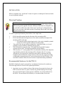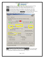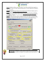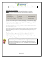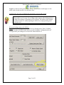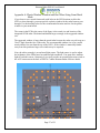
1
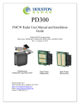
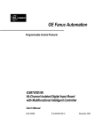
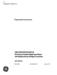
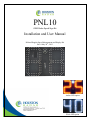
PNL10 OEM Radar Speed Sign Kit Installation and User Manual K-Band Doppler Speed Measurement and Display Kit Rev 6 May 28th, 2013 Amber LED option While LED option Houston Radar PNL10 User Manual The Doppler radar module incorporated in this device complies with part 15 of the FCC Rules. Operation is subject to the following two conditions: (1) this device may not cause harmful interference, and (2) this device must accept any interference received, including interference that may cause undesired operation. Changes or modifications not expressly approved by the party responsible for compliance could void the user's authority to operate the equipment. Any modification or use other than specified in this manual will strictly void the certification to operate the device. The radar in this device carries FCC modular approval and as such is labeled with FCC ID TIASS300. If this label is not visible when the module is installed inside another device, then the outside of the device into which the module is installed must also display a label referring to the enclosed SS300 module. This exterior label can use wording such as the following: “Contains Transmitter Module FCC ID: TIASS300” or “Contains FCC ID: TIASS300.” Any similar wording that expresses the same meaning may be used. Warning: The PNL10 is supplied in an open frame format with exposed electronics and thus is a static sensitive device. Please use static precautions when handling. Warranty does not cover damage caused by inadequate ESD procedures and practices. Note: Specifications may change without notice. Note: Not liable for typographical errors or omissions. Page 2 of 32 Houston Radar PNL10 User Manual Table Of Contents INTRODUCTION............................................................................................................. 5 INSTALLATION .............................................................................................................. 6 DIRECTION POINTING:...................................................................................................... 6 RECOMMENDED ENCLOSURE FOR THE PNL10: ................................................................ 6 HOOKUP: .......................................................................................................................... 8 Power Input: ............................................................................................................... 8 Data/PC Connection:.................................................................................................. 8 Measured Speed Output:............................................................................................. 8 IO CONNECTOR SIGNAL DESCRIPTIONS: ........................................................................ 10 DB9 RS232 Female Connector:................................................................................ 10 AUX Connector:........................................................................................................ 10 USE ................................................................................................................................... 11 FORCE ACTIVATING DISPLAY ........................................................................................ 12 TRIGGERING AN EXTERNAL CUSTOM MESSAGE: ........................................................... 12 COLLECTING AND ANALYZING IN-RADAR TRAFFIC STATISTICS ............ 13 REAL TIME TRAFFIC STATISTICS IN THE RADAR: ......................................... 13 Internal Clock: .......................................................................................................... 13 CONFIGURING THE PNL10: ..................................................................................... 14 Connect To The Unit:................................................................................................ 14 Read The Radar Configuration: ............................................................................... 15 Setup The Display Limits (Permanent Location, Rotary Switch Disabled): ............ 16 Setup The Display Limits (Portable Sign, Rotary Switch Enabled): ........................ 17 Setup White Strobe Configuration: ........................................................................... 19 Setup Display Brightness Configuration: ................................................................. 20 Setup Operating Mode Configuration: ..................................................................... 20 Write the Configuration to the PNL10: .................................................................... 21 Setup Additional Configuration Options: ................................................................. 22 Other GUI Options: View Raw Radar Config: ......................................................... 23 Other GUI Options: Save Config To File: ................................................................ 23 Other GUI Options: Load Config From File: .......................................................... 23 PNL10 SPECIFICATIONS ........................................................................................... 24 GENERAL ....................................................................................................................... 24 APPROVALS ................................................................................................................... 24 DATA INTERFACES ......................................................................................................... 24 OPTICAL......................................................................................................................... 24 MECHANICAL ................................................................................................................. 24 PERFORMANCE ............................................................................................................... 25 Page 3 of 32 Houston Radar PNL10 User Manual MECHANICAL OUTLINE DIMENSIONS: ............................................................... 26 APPENDIX A: PLASTIC WINDOW LOCATION AND SIZE WHEN USING FRONT METAL MASK ................................................................................................ 27 APPENDIX B: ACTIVATE AN EXTERNAL LED MESSAGE ABOVE A PRESET SPEED .............................................................................................................................. 28 APPENDIX C: EXPANDING TO AN OPTIONAL 3RD DIGIT TO MAKE A 3 DIGIT SPEED SIGN ...................................................................................................... 29 APPENDIX D: KEEPING TIME WITH AN EXTERNAL CLOCK BACKUP BATTERY ....................................................................................................................... 30 Page 4 of 32 Houston Radar PNL10 User Manual INTRODUCTION Congratulations on your purchase of the Houston Radar directional Doppler radar speed sign kit PNL10. This state of the art two-digit speed display with integrated ultra-low power 24GHz K-band microwave Doppler radar is specifically designed for the license free solar power or battery operated speed sign and traffic calming sign market. Utilizing high performance, ultra low power DSP (Digital Signal Processing) technology and microwave components based on a planar patch array antenna with integrated low power PHEMT oscillator, you will find that this high quality product meets your exacting standards for performance and reliability. Some of the highlights of this product include: Zero cables highly integrated design assembles into your enclosure in minutes 10.5” (27cm) digit height with 30% inter-character separation is matched to 300+ ft (90+ m) detection range of the radar for optimal display legibility Best in class power efficiency achieved by: Low power SS300 radar directly drives display thus eliminating display controller Built-in ambient light sensing and automatic brightness control Ambient temperature compensation of the LED drive voltage High efficiency boost regulator for LED drive voltage When no traffic is present, the radar automatically powers down display further reducing power consumption to only 0.1W Wide input supply voltage operation allows flexible power supply options ranging from 3, 4 or 5 cell Lithium Ion packs to 6 or 12V Lead Acid batteries without sacrificing sign efficiency Built-in rotary switch allows user to set cutoff and violator speed alerts in the field without connecting to a computer White LED strobe light and display flashing can be optionally activated to draw attention to speeding An expansion connector allows addition of a third digit or a fixed custom external message, e.g “SLOW DOWN” when speed violation is detected Built-in radar is FCC approved with CE mark and available in 24.125GHz and 24.200GHz versions for worldwide deployment Advanced In-Radar Traffic Statistics collection option now available Page 5 of 32 INSTALLATION PNL10 is supplied in an “open frame” format. It requires a weatherproof enclosure before it may be operated outdoors. Direction Pointing: The SS00 radar used in the PNL10 is directional in nature. It may be configured to detect and measure the speed of incoming or outgoing traffic. It then rejects traffic moving in the opposite direction. Direction of detection is configured via a bit in the MO variable in the radar. In the usual “speed sign” configuration the radar is set to measure and display speeds of incoming vehicles and is the default shipped from the factory. To achieve optimal performance please follow a few simple rules: PNL10 should be pointed into the direction of the oncoming traffic. PNL10 should be placed along the size of the road to minimize the angle of the oncoming traffic to the sign. o If it cannot be placed right along the side of the road, it should be pointed at least 100-150 feet up the road into oncoming traffic. The radar in the unit may pickup rotating fans, compressor blades, etc. Avoid pointing it at any machinery containing moving parts. PNL10 should be mounted at least 3 feet high from the ground for proper operation and at least 5 feet high for maximum pickup distance PNL10 utilizes 15 viewing angle LEDs. For maximum visibility of the digits the sign should be pointed at the incoming traffic with better than 10 accuracy. Alternatively, the sign may be oriented towards traffic to maximize the LED brightness from the desired viewing location on the road. We suggest providing an adjustable mounting bracket for your enclosure that will allow at least a 15 horizontal rotation to allow the user to make an adjustment during installation. Recommended Enclosure for the PNL10: The PNL10 display kit must be protected by a weatherproof enclosure for outside use. The following needs to be observed for optimal performance: 1. Any plastic cover or window in front of the unit may be mounted as close to the LEDs as desired. However, please consider any potential damage from flexing due to an external impact on the sign face (vandalism, etc.) being transferred to the PNL10. For maximum field reliability we recommend that you test the Houston Radar PNL10 User Manual proposed enclosure design to ensure the front face does not flex sufficiently to transfer an impact to the PNL10. The PNL10 provides a clear hole in the center to allow you to pass a bracing standoff through it to transfer any face impact to the back of the enclosure. Do not mount the PNL10 using this center hole. The center standoff should be mounted from the rear of the enclosure and clear through the PNL10 display PCB and stop at the front face. This will allow any front face impact force to transfer to the rear wall of the sign enclosure. 2. The optimum material for the front window/face is Lexan (Polycarbonate) plastic. 3. The optimum thickness of polycarbonate window/sign face is half wavelength at 24.125Ghz or about 137mils to 146mils (3.5 to 3.7mm) thick. a. Commonly available ¼” or 3/8” thick Lexan is not optimal and will reduce pickup range. 3/16” thick Lexan is a better choice if the recommended thickness is not available. For metric sizes, 4mm thick Lexan is a reasonably good choice. b. Frosted (anti-glare) plastic have been successfully used as well. It does not matter which side (into the sign or into the traffic) the frosting faces and is left to your discretion. 4. Other plastic materials may be used as a front window, but the optimum thickness will wary with the material’s dielectric constant. Please contact Houston Radar for details. 5. If you want to make a metal mask to hide the electronics on the PNL10 PCB with holes for the LEDs to pass through, you must provide a plastic window for the radar microwave beam to pass through. The location and size of this window is shown in Appendix A. A dxf drawing to use as a template for the metal mask is available. Please contact Houston Radar for the drawing. We strongly recommend that you prototype and test your enclosure on the road to verify that the radar detection range is not affected by your choice of plastic and mechanical design prior committing to full production. Page 7 of 32 Houston Radar PNL10 User Manual Hookup: Power Input: The PNL10 may be powered from a DC supply with output voltage between 5.6 and 18VDC. This allows great flexibility in power options including 6V or 12V (nominal) lead acid batteries (SLA), 3, 4 or 5 cell Lithium Ion (LiOn) or Lithium Iron Phosphate (LiFePO4) cells. In all cases, a highly efficient input power regulation system in the PNL10 adjusts the LED drive voltage to the optimum level required by the sign based on ambient temperature. There is no other speed sign in the world that even comes close to the resulting ultra-low power usage of the PNL10. Competing products may consume up to 5 to 10 times more power. This ultra low operational power translates directly into a longer battery life or gives you an option to power the unit from smaller batteries and smaller solar panels. As an example of the PNL10’s prowess, a 3 cell 96WHr ultra thin and light LiFePO4 battery pack weighing less than 1Kg will power the entire sign on the road for over 2 weeks of continuous operation! A convenient battery life calculator is available on our website to estimate the run time under different traffic and power supply situations. Data/PC Connection: The PNL10 features a standard RS232 interface that is used to configure the sign as explained later in this document. It also sends out the measured speed over this interface when a vehicle is detected which may be used to an external controller board to monitor the speed measured by the radar in the PNL10 kit or display on a connect PC running our Stats Analyzer or Configuration software programs. Measured Speed Output: In addition to showing the measured speed on the LED digits, the PNL10 will also send out the speed via the ASCII interface as a 3-digit speed with an optional direction indicator in standard resolution mode. Extended resolution mode adds up to 3 digits after the decimal point. The format is: [?,+]nnn[\r,\n] or in extended resolution mode [?,+]nnn[.n[n[n]]][\r,\n] The format of the speed output can be adjusted to any combination of: “?”: Optional prefix sent when 000 selected to be sent when no vehicles are detected “+”: Optional prefix sent when nnn speed is sent for incoming vehicles “nnn”: Three digit ascii speed in the units selected via the UN variable “[.n[n[n]]]”: Optional decimal point with up to 3 digits of extended resolution selected via UN variable. “\r”: Carriage Return character, optional line ending “\n”: Line Feed character, optional line ending Please see serial port configuration section for details on how to select the above format. Page 8 of 32 Houston Radar PNL10 User Manual The radar used in the PNL10 is the Houston Radar SS300. Please see the SS300 user manual for more details on setting the output format and decimal point options. The LED digits on the PNL10 will only display the whole integer speed even when the decimal point is enabled. This area deliberately left blank Page 9 of 32 IO Connector Signal Descriptions: DB9 RS232 Female Connector: Connector Pin # 1 Signal Name +VCCNote 1 Direction Description PWR Note 1 Radar VCC (battery “+“ terminal) Note 1 2 3 4 RS232 TX RS232 RX N/C OUT IN - RS232 Serial port TX pin from sign RS232 Serial port RX pin into sign Do not connect 5 6 GND N/C PWR - Signal/PWR Ground Do not connect 7 N/C - Do not connect 8 N/C - Do not connect 9 N/C - Do not connect (wrt Radar) Note 1: Pin 1 optionally connected to +VCC (supply +) if PCB pad labeled “DB9 PWR” near DB9 connector is bridged. This may be bridged by the OEM or by us if you require this feature. AUX Connector: You may optionally connect an off board speed selection switch, DB9 serial connection port or ambient light sensor. Connector Pin # 1 Signal Name Vext0 Note 2 Direction Description IN Note 2 External Light Sensor Input Note 2 2 3 4 + VCC B1 Note3 RS232 RX PWR IN IN Connected to input supply voltage + External BCD speed switch B1 pin Note3 RS232 Serial port RX pin into sign 5 6 GND RS232 TX PWR OUT Signal/PWR Ground RS232 Serial port TX from radar 7 B4 Note3 IN External BCD speed switch B4 pin Note3 8 B2 Note3 IN External BCD speed switch B2 pin Note3 (wrt Radar) Note 2: Contact us for the part number and hookup schematic for the light sensor. Two different types of sensors may be used, passive LDR or active IC (recommended). Internal light sensor must be disabled by removing R24 on the front of the PCB in order to use an external light sensor. Note 3: You may also connect an external BCD rotary switch or thumbwheel switch to use in place of the on-board rotary switch. In this case the on-board switch must be set to the “0” position or removed at the factory. Houston Radar PNL10 User Manual USE Turn on the power to the PNL10 to make it operational. The display will count up to from 1 to 10 and then blank out. The sign is now fully operational. If the rotary speed switch is enabled (see later section on configuration), turn the speed switch to the desired position (0 through 7) determined by the speed limits on the road to set the low-speed display cutoff, violator display flashing speed and the high-speed display cutoff. Typically, users set the violator flashing speed at or just above the speed limit on the road and the high-speed display cutoff at a speed sufficiently above the speed limit to capture most of the speeding traffic but not high enough to encourage “racing against the radar”. For example, for a 25mph speed limit road, the violator limit may be set to 26 mph and the low and high cutoffs will be set 15 mph below and above this value respectively. The exact values are of course left to the judgment of the user. No other action is required. The PNL10 will display the measured speed when an incoming vehicle is detected between the low-speed and high-speed limits. The display will blink at about 1.4Hz rate if the measured speed is above violator speed. This indicates to the driver that they are driving above the speed limit. If the white LED cluster is populated (this is the default, you may chose to have it removed), and enabled through the software configuration- it will strobe at a 10Hz rate. The strobe can also be configured to blink at 1.4 Hz rate when activated. Finally, if the vehicle speed is above the high-speed display cutoff, the display will be blanked. This prevents drivers from “racing against the sign” (trying to see how high a speed they can display). The strobe may be configured to stay active or go blank above this speed. As long as the radar is tracking a target between the low-speed cutoff and the high-speed cutoff, the radar will transmit the speed in user selected ASCII format over the serial interface. This may be observed via our PC based configuration tool or captured by an external user provided controller board. Monitoring or capturing this speed is not required for normal operation of the speed sign. Serial output is affected by low, high and violator speed configuration in the same way as the display panel. Page 11 of 32 Force Activating Display In order to test integrity of the LED digits, converting PNL10 into a slave display unit or any other purposes the user may activate PNL10 display by using the following procedure: 1. Make sure that PNL10 is connected to a computer or a controller with a standard RS232 cable. PNL10 provides DB9 connector on the back for this purpose. Optionally a Bluetooth wire replacement may be utilized. 2. Set RS232 parameters (baud rate, parity, etc.) to match that of the PNL10. For PNL10 these parameters are configured via RS variable in SS300 radar nonvolatile memory as described in the SS300 manual. 3. Provide power to the PNL10. 4. After the initial count-up is completed, issue “bcd” command. This command supports one or two parameters, must be terminated by a carriage return or line feed and has the following format: bcd:speed [flags] where bcd is the command, speed is the value to be displayed and flags is an optional parameter that can be used to activate or de-activate the white strobe or an optional external message board. For example: “bcd:20” will activate PNL10 and display the number 20 “bcd:55 1” will change the number to 55 and activate the strobe “bcd:55 0” or “bcd:55” will turn the strobe off and continue to display 55 “bcd:0” will deactivate display and turns off the digits. Speed value of 0 cannot be displayed since it has a special meaning. Note 1: bcd command overrides speed output from the detected targets but all other PNL10 features such as brightness control and statistics collection remain operational. Note 2: bcd command is supported by SS300 firmware version 129 and above. Triggering an External Custom Message: The PNL10 makes it very easy for OEM’s to connect an external custom LED string message like “SLOW DOWN” (or any string of LEDs arranged in a local language). This message can be activated whenever the strobe is active and will also blink if the strobe is configured to blink. A second “THANK YOU” message can also be activated by the PNL10 when the digits are turned on but the vehicle is below the limit at which the strobe will be activated. This configuration allows you to make a full functionality speed sign with a “SLOW DOWN” type message that is activated if the measured speed is above the speed limit or above the high-speed display cutoff and a “THANK YOU” activated below the speed limit. Please refer to Appendix B for a schematic of this simple external message board. Alternatively contact us to purchase this message board. Collecting and Analyzing In-Radar Traffic Statistics The PNL10 supports optional “In-Radar” advanced traffic statistics collection. This feature is sold separately. If this feature is enabled you may collect the stored statistics by using the provided Houston Radar Advanced Statistics Analyzer Windows program. This program must be installed on a MS Windows 7, Windows 2000, XP or Vista PC (32 bit and 64 bit versions) and allows the retrieval of stored statistics from the radar by using a PC serial port. It also has features to generate traffic reports, plot interactive graphs and export the raw data to a MS Excel file. Please refer to the on line help functionality of the program after you install it on your computer for detailed instructions on how to use its functionality. Real Time Traffic Statistics In the Radar: The PNL10 In-Radar stats software now features “real time” histogram statistics. These are updated as soon as a vehicle is detected and may be read out as a speed bin count “histogram”. Thus no historical records need be read out and parsed to read statistics. This feature requires a host program to be on-line to read the live statistics. Please contact Houston Radar for more information if you are interested in acquiring live statistics from the radar. Internal Clock: The PNL10 has a built in clock/calendar function. This is used to keep the time to date/time stamp the historical archive records saved by the Advanced In-Radar traffic statistics collection feature that is available as an option in the radar. The PNL10 does not feature a clock backup battery. So power must remain connected to the radar for the clock to keep time. However an external clock battery may be connected to keep time while PNL10 goes into low power sleep mode. See Appendix D for more details Configuring the PNL10: The PNL10 supports many user options and configurations that make it a very versatile device. A user-friendly MS Windows PC based graphical user interface (GUI) software is provided to make this configuration a snap for the end user. Install the Houston Radar Stats Analyzer or Houston Radar Configuration Tool provided with the sign on your MS Windows PC. After starting the installed program, click on “File->Connect to Radar…” at which time you will see the following screen. Connect To The Unit: Step 1: Connect to the PNL10 in the “Connection” tab. Ensure you get “Radar Found” message and another window with radar details. Click past these messages. Houston Radar PNL10 User Manual Read The Radar Configuration: Step 2: Click on the “Radar Setup” tab. The software will read the radar configuration and you should see this screen (actual values will depend on your PNL10). Page 15 of 32 Houston Radar PNL10 User Manual This screen contains the most frequently used settings in the PNL10. Setup The Display Limits (Permanent Location, Rotary Switch Disabled): Step 3: Setup the display limits for your permanent location. The following screen shows the simplest option with the rotary switch disabled. We will discuss the rotary switch in the next section. Page 16 of 32 Houston Radar PNL10 User Manual Step 3A: Disable the rotary switch if the sign will be in a permanent location and the display limits will be fixed (skip to next section if sign will be portable unit). Step 3B: Set the Minimum display speed. Display will be blank below this speed. Step 3C: Set the Maximum display speed. Display will be blank above this speed. Step 3D: Set the Speed Limit. Display will flash above this speed to attract further attention. Users may choose to set this slightly above the actual speed limit on the road to prevent excessive flashing if traffic is moving just above the posted speed limit. However, the end user is the best judge of this value. Step 3D Step 3B Step 3C Step 3A Setup The Display Limits (Portable Sign, Rotary Switch Enabled): Step 4: Alternatively set the display limits for your portable sign where you may turn the rotary switch (or thumbwheel switch) provided with the PNL10 to conveniently change the display limits for different locations without using a computer. Page 17 of 32 Houston Radar PNL10 User Manual Step 4A: Enable the Rotary switch and choose if you wish to shift all limits together (as shown in the image) or just the minimum display limit. The blue underline will change to reflect your choice. Step 4B: Set the Minimum Display Speed, Speed Limit and Maximum display speed to the desired value for position 0 of the switch (important!). Step 4C: Now set the rotary switch increment. This increment will apply to all display limits or just to your minimum display speed depending on the rotary switch mode you picked in Step 4A above. Step 4D: Check your setup. Click the “Display Speed Limits Table” to see the display limit values for the other positions or click on “Check Limits” button and spin the “Test Rotary Switch Position” box. The slider will move to show you the effective values. Step 4B Step 4C Step 4A Step 4D Please note that spinning this “virtual” rotary switch on the GUI does not affect the actual sign. To change the speed limits in the sign, the actual rotary switch on the back of PNL10 needs to be adjusted. The simulated values are provided as a Page 18 of 32 Houston Radar PNL10 User Manual tool to check what actual speed settings you will get when your configuration is saved to the sign. Setup White Strobe Configuration: Step 5: Set the White Strobe cluster option and blink style to your preference. If you do not wish the strobe to be activated, simply uncheck both checkboxes. The PNL10 has a white LED cluster (strobe light) arranged in a circle in between the two digits (this option may not be present in your display). The cluster strobes at a fast 10Hz rate to attract attention and may be selected to activate above the flashing speed limit as well as above the maximum display speed. Note that if enabled above the flashing speed limit, the cluster will also illuminate above the maximum display speed. Strobe light is typically used to draw attention of the driver to the display and the fact that their current vehicle speed is above the posted speed limit or that they are driving at an unsafe speed. The 10Hz modulation is implemented in the hardware and cannot be disabled via software. Contact Houston Radar if you require it to be disabled in hardware. Additionally, this strobe can be configured from this screen to blink on/off at a 1.4Hz rate together with the speed display. If you connect an external message as described in Appendix B, then that message is activated along with the strobe. Thus the strobe configuration options become the external message options as well. Note that the 10Hz strobing effect does affect the external message. However, the 1.4Hz blinking effect is propagated to the external message. Page 19 of 32 Setup Display Brightness Configuration: Step 6: The PNL10 automatically controls the display brightness for optimal visibility under all ambient lighting conditions. The ambient light is sampled by a built in light sensor located on the front face of the PCB or by an optional external light sensor wired to the AUX connector. A control algorithm computes the optimal brightness and adjusts the average LED current via a PWM circuit. PWM circuit is designed to prevent flicker and color distortion. You may chose to bias automatic brightness control algorithm towards saving battery (Battery Life Optimized) or making the display brighter and hence more noticeable (Brightness Optimized). In the “Battery Life Optimized” setting the display brightness is reduced by about 30% from the factory default setting for any ambient lighting condition. This can be particularly advantageous for portable signs operating solely off a battery and allow the sign to operate up to 30% longer under heavy traffic conditions. If you find the display brightness in-adequate then set the display to “Brightness Optimized”. Setup Operating Mode Configuration: Step 7: For normal operation of the sign on the road select “Normal Operation”. In this mode the radar will pickup actual targets in front of the unit and display them on the digits if they range between the Minimum Display Limit and Maximum Display Limit. The PNL10 also supports a “Demo Mode”. In this mode, the radar generates a preprogrammed sequence of speeds and shows them on the display. Note that the speed limits still apply to these speeds, so selecting different limits will change what speeds are displayed and if the strobe is activated. The ambient light sensor and automatic display Houston Radar PNL10 User Manual brightness control work as normal. This can be a useful tool to test the sign on a low traffic road or inside an office or trade show floor. In demo mode, the radar will not pickup and display actual traffic speeds. A power cycle is required for the change to take affect after going from Normal to Demo mode or vice-a-versa. If you change modes and save the configuration to the radar, the software will prompt you for a reboot. This allows you to change the mode from the PC without opening the PNL10 box and physically power cycling the unit. Write the Configuration to the PNL10: Step 8: Write the Configuration to the PNL10 by clicking on the “Write To Radar” button. You must click this button and be presented with the” Configuration Saved” message before your changes are saved to the connected PNL10. Step 8 Page 21 of 32 Setup Additional Configuration Options: The radar utilized in the PNL10 is the Houston Radar model SS300. It supports numerous other options like detection sensitivity, programmable serial port baud rate, different measurement units (mph, kph, fps, mps) and fractional high precision speed output over the serial port. If you wish to configure these options, click the “Detection and Units”, “Data Output” and “Hardware and IO” tables to make changes to these other infrequently adjusted settings. The SS300 user manual is also freely available on our website and we recommend that you read the SS300 user manual for more details. Other GUI Options: View Raw Radar Config: Click on this button to view the underlying radar variable configuration in a text file. This is not required in normal operation. Other GUI Options: Save Config To File: Click this button to save the radar configuration on the screen to a local file on your PC. This button will save the configuration reflected in the screen GUI. If you have made changes to the GUI but not yet saved them to the radar, you can save these changes to a local file without altering the radar. To save the configuration of the radar instead, either: 1. Click the “Save Config to File” button before making any GUI changes or 2. Click on “Advanced->Radar Configuration->Copy Config From Radar To Local File” menu item. Other GUI Options: Load Config From File: Click this button to load a radar configuration from a local file on your PC into the GUI. You can then further modify the configuration before saving it back to a file or to the radar. Simply loading the configuration does not immediately save it to the radar. You must still click the “Write To Radar” button. To directly copy a local configuration from a local file to the radar click on “Advanced->Radar Configuration->Restore Config From Local File To Radar” menu item. This is the fastest and easiest way to set the PNL10 to a known configuration you may have saved off before. Houston Radar PNL10 User Manual PNL10 SPECIFICATIONS General Operating Band Frequency Power Output Antenna Beam Pattern Polarization Supply Voltage Reverse Battery Nominal Current Draw (@12VDC including radar) Operating Temp. Weatherproof IR Remote Programmable K-Band 24.125 GHz 50Mhz (US) or 24.20Ghz (UK, Australia) 5mW 45 deg x 38 deg Linear 5.6V DC to 16V DC (18VDC Maximum) Protected Display blank: 9.5 mA Display at night: 21 mA Display at max brightness: 415 mA -40F to +185F (-40C to +85C). No. User supplied enclosure required. No Approvals Radar Approvals FCC Part 15, modular approval (US Version), CE Mark. Data Interfaces Serial Communication Data Rate Data Connector Power AUX RS232 1200 to 115200 baud DB9 Female with RS232 levels wired as a DCD. Use 3 wires straight through cable to PC RS232 port. Screw terminal default. Can be user specified. Minimum quantity order size may apply. Contact us for details. 2mm pitch 4x2rows. Sullins part # NPPN042GFNS-RC Use mating Sullins part # NRPN042MAMS-RC or equivalent Optical LED Color Brightness Viewing Angle ITE Amber (592nm ±4nm) for digits. White for strobe cluster White LED digits are available as an option. Contact us for more information. 11,000 nits (cdm) maximum, controlled automatically via onboard light sensor 550nits at night minimum 15° cone off normal Mechanical Weight Dimensions Mounting approx 450 grams (1 lbs) 11”x16”x1.1” (28 x 41 x 2.8 cm) 8x #6 screw plated through holes connected to system GND. 1x #6 center non-plated hole for passing bracing standoff from the back. Do not use to mount PNL10 PCB. Specifications continued on next page … Page 24 of 32 Houston Radar PNL10 User Manual Performance Resolution Accuracy Detection Range 0.006 mph (internal and available on serial port) rounded to whole mph (kph) when shown on display. 0.4% of reading + 0.1mph Typically 90+ m (300+ feet) for compact vehicles on open and level road with radar mounted 1.5 m (5 feet) high and pointed straight into oncoming traffic. 150+ m (500+ feet) for larger trucks, lorries and vehicles with inherently large radar cross-section. May vary with installation and road conditions. Detection range specified is typical for speeds between 20kph and 88kph (12 to 55 mph). It tapers off below and above this speed range. At the low end of the speed range (2mph (5kph), the detection range is about 34+ m (110+ feet). PNL10 is not recommended for roads with speeds above 90 kph (56 mph) due to reduced range and tracking time. Contact Houston Radar if a low speed operation (down to 0.25 mph) is required. Page 25 of 32 Mechanical Outline Dimensions: Rev 1.3 PCB. Dimensions in inches [mm] Houston Radar PNL10 User Manual Appendix A: Plastic Window Location and Size When Using Front Metal Mask If you chose to use a metal front mask (with holes in the LED locations to allow the LED’s to show through), you must provide a plastic window for the radar beam to pass through. Use the drawing below for the recommended location and size for the plastic window in your metal mask. The cutout in the PCB in the center of the figure is the actual size and location of the integrated SS300 radar. The dotted and dashed larger rectangle is the suggested window size. The suggested window is larger than the actual radar because the radar waves diverge at a 38x45 angle from the face of the radar. The recommended window size is for a metal mask within a few mm from the top of the LED’s. If the window is materially further away from this position a larger size window may be required. Note: the white rectangle is an on-board light sensor. The light sensor is used to adjust the brightness of the LEDs based on ambient light conditions. You must allow ambient light to reach this sensor. Alternatively you may provide an external light sensor wired to the AUX connector on the back of PNL10. Contact Houston Radar for more details. All dims in mm except those shown in inches (marked with a ”). Page 27 of 32 Houston Radar PNL10 User Manual Appendix B: Activate An External LED Message Above a Preset Speed Many speed signs have an external VMS type message that gets activated above a preset speed. This message may spell out text like “SLOW DOWN” or any other message in a local language. Emoticons like a “sad face” are also commonly used in certain countries. The schematic below shows how to connect a string of LEDs that can be triggered by the PNL10 above a user set speed limit. The message is activated together with the on-board strobe. Additionally this message will blink if the user chooses the on-board strobe to blink. The 10Hz strobing effect does not apply to the message. Connect as many strings of LEDs as required to form a message. For simplification only two strings are shown on the schematic. Then physically arrange the LED’s in the form of the message or emoticon you desire. All LEDs will be lit when the on-board strobe is activated. The message can be programmed to activate above any user-selected speed. Furthermore this speed can be adjusted in the field through the rotary switch located on the back of PNL10. For most configuration purposes this eliminates the need to connect a computer in the field. If you wish to use a “SLOW DOWN” message we have this LED only board available for purchase. A second “THANK YOU” message (or a “happy face” emoticon) can be activated below the user-selected speed when connected to pin #4 of P2. Thus you can build a “SLOW DOWN”/”THANK YOU” type of display easily. Please contact us for details if you wish to utilize this feature. Page 28 of 32 Appendix C: Expanding to an Optional 3rd Digit to Make a 3 Digit Speed Sign You may easily expand the PNL10 to a 3rd digit (to show the 100’s place value) via an LED only PCB. All the drivers are already built on the PNL10 PCB. Note: The expansion connector to drive this 3rd digit is shared with the on-board strobe. Hence you must disable the on-board strobe for this scheme to work. Contact us for details on how to do that or please order your PNL10 without the white strobe populated. Houston Radar PNL10 User Manual Appendix D: Keeping Time With an External Clock Backup Battery Our popular “Advanced In-Radar Traffic Statistics” is available as an option in the SS300 radar as well as the PNL10 display (which uses the SS300 radar as the speed measurement element). The In-Radar traffic statistics option generates time-stamped historical records that are saved in the on-board FLASH memory. Hence, the SS300 radar needs to keep calendar date and time once it is set from a device (typically a PC running our configuration or stats analyzer software). If the SS300 is used in a configuration that may disrupt power, an external clock backup battery must be connected as suggested below. Note: Alternatively the clock may be manually reset from an external controller to the correct time once power is restored. Step 1: Set the “Enable Low Power Sleep” mode bit in the MD variable (this is factory default so no operation is required if you have not changed it). The radar will now enter low power sleep mode where it will maintain the clock once the external VCC supply voltage enters the sleep region as shown in the provided diagram. The radar will resume normal operation once the input VCC voltage returns to the “Run” region. Step 2: Setup an arrangement to switch in a 4.5V to 6.8V clock backup battery into the VCC line once main power is removed. This may be done two ways: Method 1: “Wire OR” the backup source and the main VCC through two low drop diodes as shown on the next page. Diode voltage drop must be taken into account when determining backup voltage. For example if the diode voltage drop is 0.6V the backup supply voltage must be between 5.1 and 7.4 volt. We recommend a low drop (<0.3V) low leakage diode particularly for the clock battery when using a lithium battery that cannot tolerate any significant reverse charging current. Method 2: If the main supply will not be removed, but rather switched off, install a Zener diode across the power switch such that the radar continues to receive between 4.5 and 6.8VDC when the power is turned off via the switch (with the rest dropped by the zenner). The power consumed by the radar in low power sleep mode is as follows: Installed Configuration Microamps Sleep Mode Sleep Mode Consumed in sleep Enter Voltage Exit Voltage SS300 in PNL10 display 7V nominal 8V nominal. 745 uA 20 A 6.5V min 8.7V max Note 1: Connecting a RS232 cable to the radar or forcing the RS232 interface to ON does not affect the sleep power usage. Page 30 of 32 Houston Radar PNL10 User Manual Note 2: The radar power usage is approximately constant regardless of the input supply voltage in the sleep region. This is different when the radar is in the operational region where is behaves as a constant power device (current goes down with increasing voltage). Method 1 to provide clock backup power (Wired OR with two supplies): SS300 Standalone Low Drop voltage diodes to Wire OR the batteries. +VCC D2 + OR D1 + PNL10 Display GND Clock Backup Battery (4.7V to 6.7V assuming 0.2v diode drop). Main Battery (8.6V to 18 V. May be removed. Backup battery will provide power to maintain clock. Ensure it cannot be removed or disconnected. Note: Please use low forward voltage drop diodes to maintain efficiency. Also carefully consider the reverse leakage currents if using a lithium backup battery which is very intolerant of such currents. D1 could be a signal diode that has very low reverse currents. D2 needs to be rated for >=1A. Method 2 to provide clock backup power (main supply switched off but not removed): Zener diode to drop enough voltage from main battery to supply between 4.5V and 6.5V to SS300 * See Note 1 SS300 Standalone +VCC + OR PNL10 Display GND Main power ON/OFF switch puts SS300/PNL10 into low power sleep mode when turned OFF. Zenner still provides enough voltage and current to allow SS300 to keep time with minimal power usage. Note 1: The zenner value should be “X” and satisfy the following two equations: Eq1 fully charged battery: Bmax – X = 6.5 to 4.5 Eq2 fully discharged battery: Bmin – X = 6.5 to 4.5 Page 31 of 32 Main Battery (8.6V to 18 V. May NOT be removed if time is to be maintained when switch is in OFF position.