1
MDS™ ORBIT MCR
Edge Connect Router
MDS 05-6632A01, Rev. E
August 2015
Technical Manual
MDS™ ORBIT ECR
Technical Manual
Multiservice Connect Router
View instructional videos: Orbit™ MCR Learning and Development
YouTube Channel
Quick-Start instructions for this product are contained in publication 05-6709A01.
Visit our website for downloadable copies of all documentation at www.gemds.com.
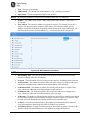
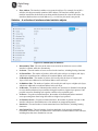
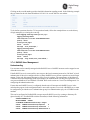
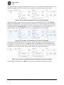
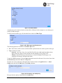
TABLE OF CONTENTS
COPYRIGHT AND TRADEMARK ................................................................................................................ 7
RF REGULATORY INFORMATION ............................................................................................................. 7
SAFETY REGULATORY INFORMATION ................................................................................................... 8
PRODUCT COUNTRY CERTIFICATION INFORMATION – (NON-NA/EU) ............................................. 12
1.0
PRODUCT OVERVIEW AND APPLICATIONS ............................................................................. 15
1.1
INTRODUCTION .............................................................................................................................. 15
1.1.1
PRODUCT VARIATIONS .............................................................................................................................. 15
1.1.2
ABOUT THIS MANUAL ............................................................................................................................... 16
2.0
PRODUCT DESCRIPTION ............................................................................................................. 18
2.1
KEY FEATURES .............................................................................................................................. 18
2.2
INTERFACE TYPES ......................................................................................................................... 18
2.3
NETWORK INTERFACE CARDS (NICS) ............................................................................................. 18
2.3.1
4G LTE/CDMA (VERIZON ONLY).............................................................................................................. 18
2.3.2
4G LTE, HSPA+, GSM/GPRS (EMEA/APAC) ....................................................................................... 19
2.3.3
4G LTE, HSPA+, GSM/GPRS (NORTH AMERICA) .................................................................................... 19
2.3.4
3G CELL ................................................................................................................................................. 19
2.3.5
900 MHZ UNLICENSED ............................................................................................................................. 19
2.3.6
LICENSED NARROWBAND .......................................................................................................................... 20
2.4
TYPICAL APPLICATIONS .................................................................................................................. 21
2.5
MCR AND ECR CONNECTORS AND INDICATORS ............................................................................. 21
2.6
GROUNDING CONSIDERATIONS ....................................................................................................... 27
2.7
MOUNTING OPTIONS ...................................................................................................................... 28
2.7.1
2.8
3.0
OPTIONAL DIN RAIL MOUNTING ................................................................................................................ 28
ANTENNA PLANNING AND INSTALLATION .......................................................................................... 29
DEVICE MANAGEMENT ................................................................................................................ 34
3.1
INITIAL SETTINGS OVERVIEW .......................................................................................................... 37
3.1.1
SETTING BASIC PARAMETERS—FIRST STEPS ............................................................................................. 37
3.1.2
ONE-TIME “RECOVERY” PASSWORDS ........................................................................................................ 37
3.1.3
CHANGE DEFAULT PASSWORDS ................................................................................................................ 40
3.1.4
SECURITY REVIEW ................................................................................................................................... 41
3.2
PRECONFIGURED SETTINGS ........................................................................................................... 41
3.3
SPECIFIC APPLICATION EXAMPLES USING DEVICE MANAGER ........................................................... 42
3.4
USING THE COMMAND LINE INTERFACE (CLI) .................................................................................. 48
3.4.1
DIFFERENCES BETWEEN SERIAL AND SSH ................................................................................................. 48
3.4.2
ESTABLISHING COMMUNICATION—SERIAL INTERFACE ................................................................................. 48
3.4.3
USING THE CLI ........................................................................................................................................ 49
3.4.4
CLI QUICK REFERENCE TABLE .................................................................................................................. 50
3.4.5
SPECIFIC EXAMPLES USING CLI ................................................................................................................ 52
3.5
INTERFACE CONFIGURATION........................................................................................................... 56
3.5.1
SERIAL INTERFACE ................................................................................................................................... 56
3.5.2
CELL....................................................................................................................................................... 61
MDS 05-6632A01, Rev. E
MDS Orbit MCR/ECR Technical Manual
iii
3.5.3
W IFI ....................................................................................................................................................... 74
3.5.4
UNLICENSED 900 MHZ ISM (NX915) ........................................................................................................ 90
3.5.5
3.6
3.6.1
DEVICE OVERVIEW ................................................................................................................................. 143
3.6.2
EVENT LOGGING .................................................................................................................................... 143
3.6.3
IPERF SERVER SERVICE ......................................................................................................................... 150
3.6.4
SUPPORT BUNDLE .................................................................................................................................. 152
3.7
SYSTEM CONFIGURATION AND SETUP ........................................................................................... 154
3.7.1
DATE, TIME AND NTP ............................................................................................................................. 154
3.7.2
GEOGRAPHICAL-LOCATION ...................................................................................................................... 157
3.7.3
USER MANAGEMENT AND ACCESS CONTROLS .......................................................................................... 158
3.7.4
RADIUS USER MANAGEMENT ................................................................................................................ 161
3.7.5
FIRMWARE MANAGEMENT ....................................................................................................................... 163
3.7.6
TAMPER DETECTION ............................................................................................................................... 171
3.7.7
CONFIGURATION SCRIPTS ....................................................................................................................... 174
3.7.8
DNS..................................................................................................................................................... 178
3.8
NETWORKING SERVICES AND ROUTING ......................................................................................... 181
3.8.1
NETWORK ............................................................................................................................................. 181
3.8.2
LAN ..................................................................................................................................................... 185
3.8.3
VLAN OPERATION ................................................................................................................................. 189
3.8.4
BRIDGING .............................................................................................................................................. 193
3.8.5
ROUTING ............................................................................................................................................... 196
3.8.6
STATIC NEIGHBOR ENTRIES .................................................................................................................... 200
3.8.7
ACCESS CONTROL LIST (PACKET FILTERING / FIREWALL) ........................................................................... 203
3.8.8
SOURCE NAT (MASQUERADING) ............................................................................................................. 215
3.8.9
DESTINATION NAT (PORT FORWARDING) ................................................................................................. 223
3.8.10
STATIC NAT .......................................................................................................................................... 230
3.8.11
VPN ..................................................................................................................................................... 234
3.8.12
DHCP SERVICE .................................................................................................................................... 248
3.8.13
TERMINAL SERVICE ................................................................................................................................ 252
3.8.14
REMOTE MANAGEMENT INTERFACES ........................................................................................................ 260
3.8.15
REMOTE MANAGEMENT SERVICE ............................................................................................................. 265
3.8.16
QUALITY OF SERVICE (QOS) ................................................................................................................... 273
3.8.17
SNMP .................................................................................................................................................. 283
3.8.18
NETWORK MONITOR SERVICE ................................................................................................................. 303
3.8.19
NETWORK LINK FAILOVER/FAILBACK ........................................................................................................ 305
3.8.20
DYNAMIC ROUTING................................................................................................................................. 327
3.8.21
GPS SERVICE ....................................................................................................................................... 337
3.8.22
DYNAMIC DNS ...................................................................................................................................... 339
3.9
iv
LICENSED NARROWBAND (LN) ................................................................................................................ 121
SYSTEM HEALTH AND STATUS ...................................................................................................... 143
PUBLIC KEY AND CERTIFICATES.................................................................................................... 342
3.9.1
CERTIFICATE MANAGEMENT AND 802.1X AUTHENTICATION........................................................................ 342
3.9.2
PRIVATE KEYS ....................................................................................................................................... 343
3.9.3
CA CERTIFICATES .................................................................................................................................. 347
3.9.4
CLIENT CERTIFICATES ............................................................................................................................ 350
MDS Orbit MCR/ECR Technical Manual
MDS 05-6632A01, Rev. E
3.9.5
FIRMWARE CERTIFICATES ....................................................................................................................... 354
3.9.6
SCEP AND CA CONFIGURATION ............................................................................................................. 357
4.0
TECHNICAL REFERENCE .......................................................................................................... 361
4.1
TROUBLESHOOTING ..................................................................................................................... 361
4.1.1
4.2
LED STATUS INDICATORS ....................................................................................................................... 361
TECHNICAL SPECIFICATIONS ........................................................................................................ 363
5.0
GLOSSARY OF TERMS AND ABBREVIATIONS....................................................................... 369
6.0
APPENDIX A – COMMAND LINE INTERFACE (CLI) FEATURES ............................................ 373
6.1
OPERATIONAL MODE ................................................................................................................... 373
6.2
CONFIGURATION MODE ................................................................................................................ 373
6.3
CHANGING CONFIGURATION DATA ................................................................................................ 373
6.4
INPUTTING VALUES ...................................................................................................................... 373
6.5
INPUT OF A LIST OF VALUES ......................................................................................................... 373
6.6
TAB-COMPLETION ........................................................................................................................ 374
6.7
CLI ENVIRONMENT ...................................................................................................................... 375
6.8
COMMAND OUTPUT PROCESSING ................................................................................................. 376
6.9
COUNT THE NUMBER OF LINES IN THE OUTPUT ............................................................................. 377
6.10 SEARCH FOR A STRING IN THE OUTPUT ......................................................................................... 377
6.11 REGULAR EXPRESSIONS .............................................................................................................. 378
6.12 DISPLAY LINE NUMBERS............................................................................................................... 378
6.13 SHOWING INFORMATION ............................................................................................................... 379
6.14 CONTROL SEQUENCES................................................................................................................. 379
6.15 COMMANDS ................................................................................................................................. 379
6.16 OPERATIONAL MODE COMMANDS ................................................................................................. 380
6.17 CONFIGURE MODE COMMANDS .................................................................................................... 383
APPENDIX B – INTEGRITY MEASUREMENT AUTHORITY (IMA) ........................................... 387
7.0
7.1
UNDERSTANDING ......................................................................................................................... 387
7.2
CONFIGURING.............................................................................................................................. 387
7.2.1
OBTAINING CONFIGURATION FILE HASH ................................................................................................... 388
7.3
MONITORING ............................................................................................................................... 388
7.4
IMA TROUBLESHOOTING .............................................................................................................. 389
APPENDIX C – COMMON EVENT EXPRESSION (CEE) ........................................................... 391
8.0
8.1
EVENT TAXONOMY ....................................................................................................................... 391
8.2
EVENT FIELD DICTIONARY ............................................................................................................ 391
8.3
EVENT ENCODING & TRANSPORT ................................................................................................. 392
8.3.1
EXAMPLES ............................................................................................................................................. 392
8.3.2
SYSLOG PRIVAL ................................................................................................................................... 393
8.3.3
SYSLOG APP-NAME ............................................................................................................................. 393
8.3.4
SYSLOG MSG ........................................................................................................................................ 393
8.4
CONFIGURING.............................................................................................................................. 393
8.5
MONITORING ............................................................................................................................... 394
9.0
APPENDIX D – MANAGING SIGNED FIRMWARE .................................................................... 395
10.0
APPENDIX E – OBTAINING PROVISIONED 4G/LTE SERVICE (VERIZON) ............................ 397
MDS 05-6632A01, Rev. E
MDS Orbit MCR/ECR Technical Manual
v
10.1 UNDERSTANDING ......................................................................................................................... 397
10.2 BEFORE CONTACTING VERIZON .................................................................................................... 397
10.3 ESTABLISHING A CELL SERVICE PLAN ........................................................................................... 397
11.0
APPENDIX F – NX915 MODULE FREQUENCIES ...................................................................... 399
12.0
APPENDIX G – LICENSES .......................................................................................................... 403
12.1 OPEN SOURCE LICENSE DECLARATION ......................................................................................... 403
13.0
vi
APPENDIX H – COUNTRY SPECIFIC INFORMATION .............................................................. 405
MDS Orbit MCR/ECR Technical Manual
MDS 05-6632A01, Rev. E
Copyright and Trademark
This manual and all software described herein is protected by Copyright: 2015 GE MDS, LLC. All rights
reserved. GE MDS, LLC reserves its right to correct any errors and omissions in this publication.
RF Regulatory Information
RF Safety Notice (English and French)
RF Exposure
l’exposition aux RF
Concentrated energy from a directional antenna may pose a health hazard to humans.
Do not allow people to come closer to the antenna than the distances listed in the
table below when the transmitter is operating. More information on RF exposure can
be found online at the following website:
www.fcc.gov/oet/info/documents/bulletins
Concentré d'énergie à partir d'une antenne directionnelle peut poser un risque pour
la santé humaine. Ne pas permettre aux gens de se rapprocher de l'antenne que les
distances indiquées dans le tableau ci-dessous lorsque l'émetteur est en marche. Plus
d'informations sur l'exposition aux RF peut être trouvé en ligne à l'adresse suivante:
www.fcc.gov/oet/info/documents/bulletins
Antennas must not be co-located. All transmission antennas must be at least 20 cm apart to comply with
FCC co-location rules.
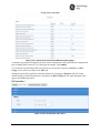
Orbit Device vs. Minimum RF Safety Distance
Radio Module
Equipped
Minimum Safety Distance
from Antenna
Cell
33 cm
NX915
23 cm
LN400
143 cm - using 5 dBi antenna
254 cm - using 10 dBi antenna
507 cm - using 16 dBi antenna
Other models
Consult factory prior to operation.
NOTE THE ORBIT MCR/ECR DOES NOT SUPPORT VOICE COMMUNICATIONS
FCC Class A Notice
This device complies with Part 15 of the FCC Rules. Operation is subject to the following two conditions:
This device may not cause harmful interference.
This device must accept any interference received, including interference that may cause
undesired operation.
Note: This equipment has been tested and found to comply with the limits for a Class A digital device,
pursuant to Part 15 of the FCC Rules. These limits are designed to provide reasonable protection against
harmful interference when the equipment is operated in a commercial environment. This equipment
generates, uses, and can radiate radio frequency energy, and if it is not installed and used in accordance
with the instruction manual, it may cause harmful interference to radio communications. Operation of this
equipment in a residential area is likely to cause harmful interference, in which case the user will be
required to correct the interference at his own expense.
MDS 05-6632A01, Rev. E
MDS Orbit MCR/ECR Technical Manual
7
Modifications: Any modifications made to this device that are not approved by GE MDS LLC, Inc. may
void the authority granted to the user by the FCC to operate this equipment.
Industry Canada Notice
This Class A digital apparatus complies with Canadian ICES-003.
Cet appareil numérique de la classe A est conforme à la norme NMB-003 du Canada.
Operational Safety Notices
The MDS Orbit MCR may not be used in an environment where radio frequency equipment is prohibited
or restricted in its use. This typically includes aircrafts, airports, hospitals, and other sensitive electronic
areas.
Do not operate RF devices in an environment that may be susceptible to radio interference resulting in
danger, specifically:
Areas where prohibited by law - Follow any special rules and regulations and obey all signs and
notices. Do not use the Orbit MCR when you suspect that it may cause interference or danger.
Near Medical and life support equipment - Do not use the Orbit MCR in any area where medical
equipment, or life support equipment may be located, or near any equipment that may be susceptible
to any form of radio interference.
All cables and conductors making connections to the units need to be rated at 85 °C or higher.
Use Copper Conductors Only
Use 18 AWG wire
FCC IDs of Installed Transmitters
As of the printing date, the following identifiers are assigned to the modules listed below. For the latest,
official listings of all agency approvals, please contact your factory representative.
Config. Id – Radio Desc.
FCC ID
IC ID
E4V - 4G/3G CELL Modem
PKRNVWE362
3229B:E362
3G1 - 3G CELL Modem
RI7HE910
5131A-HE910
E4S,E45 - 4G/3G CELL Modem
n/a
n/a
E4N, E41, E42, E43, E44 - 4G/3G CELL
Modem
N7NMC7355
2417C-MC7355
WIFI Module
M4Y-ZCN722MV1
3195A-ZCN722MV1
NX915 Module
E5MDS-NX915
101D-NX915
LN400 Module
E5MDS-LN400
101D-LN400
Country-Specific Installation Data
Refer to APPENDIX H – Country Specific Information at the back of this manual for important notices
regarding installation in specific countries.
Safety Regulatory Information
CE Mark and RTTE Notice
This product, using the "WIFI internal radio module" and “CELL modem”, is CE marked and compliant
with the RTTE directive. Other configurations will be added for EU use in future releases.
8
MDS Orbit MCR/ECR Technical Manual
MDS 05-6632A01, Rev. E
Servicing Precautions
No user-serviceable parts are contained inside this equipment. Opening of the unit by unauthorized
personnel voids the warranty. All servicing must be performed by an authorized repair facility.
When servicing energized equipment, be sure to wear appropriate Personal Protective Equipment (PPE).
During internal service, situations could arise where objects accidentally contact or short circuit
components and the appropriate PPE would alleviate or decrease the severity of potential injury. When
servicing equipment, all workplace regulations and other applicable standards for live electrical work
should be followed to ensure personal safety.
Manual Revision and Accuracy
This manual was prepared to cover a specific version of firmware code. Accordingly, some screens and
features may differ from the actual unit you are working with. While every reasonable effort has been
made to ensure the accuracy of this publication, product improvements may also result in minor
differences between the manual and the product shipped to you. If you have additional questions or need
an exact specification for a product, please contact GE MDS using the information at the back of this
guide. In addition, manual updates can be found on our web site at www.gemds.com .
Environmental Information
The manufacture of this equipment has required the extraction and use of natural resources. Improper
disposal may contaminate the environment and present a health risk due to hazardous substances
contained within. To avoid dissemination of these substances into our environment, and to limit the
demand on natural resources, we encourage you to use the appropriate recycling systems for disposal.
These systems will reuse or recycle most of the materials found in this equipment in a sound way. Please
contact GE MDS or your supplier for more information on the proper disposal of this equipment.
Battery Disposal—This product may contain a battery. Batteries must be disposed of properly, and may
not be disposed of as unsorted municipal waste in the European Union. See the product documentation for
specific battery information. Batteries are marked with a symbol, which may include lettering to indicate
cadmium (Cd), lead (Pb), or mercury (Hg). For proper recycling return the battery to your supplier or to a
designated collection point. For more information see:
www.weeerohsinfo.com.
Product Test Data Sheets
Test Data Sheets showing the original factory test results for this unit are available upon request from the
GE MDS Quality Leader. Contact the factory using the information at the back of this manual. Serial
numbers must be provided for each product where a Test Data Sheet is required.
UL - CSA/us Notice
This product is approved for use in Class 1, Division 2, Groups A, B, C & D Hazardous Locations. Such
locations are defined in Article 500 of the National Fire Protection Association (NFPA) publication
NFPA 70, otherwise known as the National Electrical Code. The transceiver has been recognized for use
in these hazardous locations by the Canadian Standards Association (CSA) which also issues the US mark
of approval (CSA/US). The CSA Certification is in accordance with CSA STD C22.2 No. 213-M1987.
CSA Conditions of Approval: The transceiver is not acceptable as a stand-alone unit for use in the
hazardous locations described above. It must either be mounted within another piece of equipment which
is certified for hazardous locations, or installed within guidelines, or conditions of approval, as set forth
by the approving agencies. These conditions of approval are as follows: The transceiver must be mounted
within a separate enclosure which is suitable for the intended application. The antennas are not intended
to be installed and mounted in a Class 1, Division 2 hazardous location. The antenna feedline, DC power
cable and interface cable must be routed through conduit in accordance with the National Electrical Code.
Installation, operation and maintenance of the transceiver should be in accordance with the transceiver's
MDS 05-6632A01, Rev. E
MDS Orbit MCR/ECR Technical Manual
9
installation manual, and the National Electrical Code. Tampering or replacement with non-factory
components may adversely affect the safe use of the transceiver in hazardous locations, and may
void the approval. A power connector with screw-type retaining screws as supplied by GE MDS must be
used.
EXPLOSION
HAZARD!
Do not disconnect equipment unless power has been switched off or the area is
known to be non-hazardous. Refer to Articles 500 through 502 of the National
Electrical Code (NFPA 70) for further information on hazardous locations and
approved Division 2 wiring methods.
MCR ATEX Directive Compliance Information
The Orbit MCR products are ATEX Compliant with the “Zone 2, Cat 3" requirements pending the proper
installation requirements listed below.
All RF modules contained within the Orbit MCR have a conducted RF power maximum limit of 2W.
The MCR products were evaluated based on the following ratings as per SIRA 14ATEX4119X:
II 3 G
Ex nA IIC T4 Gc
Amb -30°C to +70°C
T4 (max surface temp 70°C)
Decoded:
II - Equipment Group - Electrical equipment intended for use in places with an explosive gas
atmosphere other than mines susceptible to firedamp
3 G - Zone 2 - Normal Protection level Gas - Provides a low level of protection and is intended for
use in a Zone 2 hazardous area
Ex nA - Gas & Air Mixture Zone 2 protection - Non-Sparking
IIC - Gas Group IIC - Hydrogen/Acetylene
T4 - temperature classification (max surface temp 70°C)
Gc - Gas atmospheres - assured level of protection against becoming an ignition source in normal
operation
ETSI/CE Standards: (subject to revision)
- EN 55022: 2010
- EN 55024: 2010
- EN 60950-1 2006 +A1:2010; +A11:2009; +A12:2011
10
MDS Orbit MCR/ECR Technical Manual
MDS 05-6632A01, Rev. E
-
EN 62311: 2008
EN 300 328: V1.7.1
EN 300 440-2: V1.4.1
EN 301 489-1: V1.9.2
EN 301 489-3: V1.4.1
EN 301 489-7: V1.3.1
EN 301 489-17: V2.2.1
EN 301 489-24: V1.5.1
EN 301 511: V9.0.2
EN 301 908-1: V5.2.1
EN 301 908-2: V5.2.1
ATEX Special Conditions for Safe Use as per SIRA 14ATEX4119X:
Tighten wire clamps to 5 in-lb (0.6 Nm)
The 60Vdc rated supply shall be protected such that transients are limited to a maximum of 84Vdc;
no such protection is required for the signal lines.
The device shall be installed in an enclosure that maintains an ingress protection rating of at least
IP54 and meets the enclosure requirements of EN 60079-0 and EN 60079-15. The installer shall
ensure that the maximum ambient temperature of the module when installed is not exceeded.
The USB connection shall only be used in an unclassified (non-hazardous) area.
The SIM card shall be connected / disconnected only in a non-hazardous area or when the device is
not energized.
MDS 05-6632A01, Rev. E
MDS Orbit MCR/ECR Technical Manual
11
Product Country Certification Information – (Non-NA/EU)
MCR-3G Selected Country Certification Information
Argentina
CNC- C-14361
Australia
Brazil
Homologation Number = 1423-14-0450
UCC/EAN-128 Code = (01) 0789 8934163051
Este equipamento opera em caráter secundário, isto é, não tem direito a proteção contra interferência
prejudicial, mesmo de estações do mesmo tipo, e não pode causar interferência a sistemas operando em
caráter primário.
Este produto está homologado pela Anatel, de acordo com os procedimentos regulamentados pela
Resolução nº 242/2000 e atende aos requisitos técnicos aplicados, incluindo os limites de exposição da
Taxa de Absorção Específica referente a campos elétricos, magnéticos e eletromagnéticos de
radiofreqüência, de acordo com as Resoluçãos nº 303/2002 e 533/2009.
Este dispositivo está em conformidade com as diretrizes de exposição à radiofreqüência quando
posicionado a pelo menos 20 centímetro de distância do corpo. Para maiores informações, consulte o site
da ANATEL – www.anatel.gov.br
Japan
12
MDS Orbit MCR/ECR Technical Manual
MDS 05-6632A01, Rev. E
Mexico
IFT number [IFT] = RTIGEGE14-0827-A1
IFT number [IFT] = RCPGEGE14-1031
La operación de este equipo está sujeta a las siguientes dos condiciones:
1. es posible que este equipo o dispositivo no cause interferencia perjudicial y
2. este equipo o dispositivo debe aceptar cualquier interferencia, incluyendo la que pueda
causar su operación no deseada.
New Zealand
Philippines
Conformity Number: ESD-GEC-1402584
South Africa
UAE
Registered number = ER0133084/14
Dealer number = DA0132013/14
ECR Selected Country Certification Information
TBD
MDS 05-6632A01, Rev. E
MDS Orbit MCR/ECR Technical Manual
13
14
MDS Orbit MCR/ECR Technical Manual
MDS 05-6632A01, Rev. E
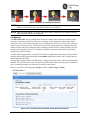
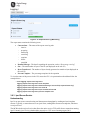
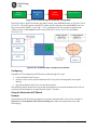
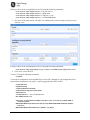
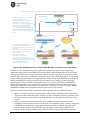
1.0 Product Overview and Applications
1.1 Introduction
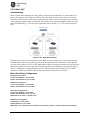
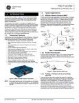
This manual describes the MDSTM Orbit Multiservice Connect Router (MCR) (Figure 1-1), and the
MDSTM Orbit Edge Connected Router (ECR) (Figure 1-2) . The unit is a highly secure, industrial grade,
wireless communication product for broad-based applications, including control center monitoring, well
site pad operations and video surveillance. It serves the need for localized WiFi communications with a
cellular back-up or backhaul option, while providing the extended temperature range and industrial-grade
packaging inherent to GE MDS products. These features allow the best use of communication options at
each installation site.
Figure 1-1. MCR-4G Unit
(Standard 2E1S configuration shown)
Figure 1-2. ECR-900 Unit
With a common hardware architecture and user interface, the MCR and ECR offers flexibility in network
design and application, with simplified training, maintenance and deployment costs. GE MDS provides
an array of communication products with multiple interface options and a variety of enclosures to give
customers the choice and flexibility to design their communications network to meet geographic and
industry specific challenges. Information on other GE MDS products can be found by visiting our website
at www.gemds.com.
GE MDS has produced a series of instructional videos for configuration and setup of the Orbit
MCR products on YouTube™. These are available free of charge at: http://tinyurl.com/pey2ull
1.1.1 Product Variations
The MDS™ Orbit MCR is factory configured with various Network Interface Cards (NICs), based on
order selection.
MDS 05-6632A01, Rev. E
MDS Orbit MCR/ECR Technical Manual
15
The label on the bottom of the unit identifies the radio model as GE MDS MCR. It includes the device
serial number and agency/regulatory identifications, including IDs for applicable embedded modules. See
“Agency/Regulatory Approvals” on Page 365 for more information.
Orbit MCR devices with specific network interfaces may be referred to with the common names below:
MCR-4G — Name for the product when configured with 4G/LTE (Verizon ONLY).
MCR-4GS — Name for the product when configured with 4G/LTE (EMEA/APAC)
MCR-4GN — Name for the product when configured with 4G/LTE (North America).
MCR-3G — Name for the product when configured with 3G.
MCR-900 — Name for the product when configured with unlicensed 900 MHz (FHSS and DTS).
MCR-LN — Name for the product when configured with licensed narrowband QAM radios.
The MDS™ Orbit ECR is factory configured with various Network Interface Cards (NICs), based on
order selection.
The label on the bottom of the unit identifies the radio model as GE MDS ECR. It includes the device
serial number and agency/regulatory identifications, including IDs for applicable embedded modules. See
“Agency/Regulatory Approvals” on Page 365 for more information.
Orbit ECR devices with specific network interfaces may be referred to with the common names below:
ECR-4G — Name for the product when configured with 4G/LTE (North America).
ECR-4GS — Name for the product when configured with 4G/LTE (EMEA/APAC)
ECR-3G — Name for the product when configured with 3G.
ECR-900 — Name for the product when configured with unlicensed 900 MHz (FHSS and DTS).
ECR-LN — Name for the product when configured with licensed narrowband QAM radios.
1.1.2 About This Manual
This manual is intended for systems engineers, network administrators and others responsible for
planning, commissioning, using and troubleshooting the wireless system. Installation steps are not
included in this publication. For installation instructions, refer to the companion Orbit MCR Setup Guide,
part no. 05-6709A01 or Orbit ECR Setup Guide, part no. 05-6709A02 Electronic copies of all user
documentation are available free of charge at www.gemds.com
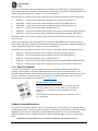
INSTALLATION & SETUP GUIDES
The Orbit MCR Setup Guide, part no. 05-6709A01 and Orbit
ECR Setup Guide, part no. 05-6709A02 contain installation
instructions, as well as basic tartup information for these
products.
All GE MDS user manuals and updates are available online at
www.gemds.com
Software Command Notations
The product is designed for software control via a connected PC. As such, there are no external controls
or adjustments present. To show the names of software commands, keyboard entries, or other information
displayed on a PC screen, a bolded font is used throughout the manual. In the case of tabular data
displayed on a PC screen, a variation on this font is used to maintain proper layout. See examples that
follow.
Bolded font example (used in text for software commands and keyboard entries)
16
MDS Orbit MCR/ECR Technical Manual
MDS 05-6632A01, Rev. E
Bolded font example (used to show tables displayed on a PC screen)
In the Device Management section of this manual (Page 34), there are a number of command strings
where information is presented by the unit and a reply is required from the user. In such cases,
information from the unit is shown in a non-bolded font and the user response is shown in bold. For
example:
(none) login: admin
Further, in some cases, command lines will be shown with non-bolded, italicized text contained within
the string. Such text indicates the need for user-supplied variable parameters, such as the name of an item.
For example:
% set interfaces interface
myBridge type bridge
In the above example, you would enter the specific name of your bridge to complete the entry.
NOTE The LAN port should be assigned IP addresses only if it is a routed interface (that is, not in a
bridge).
NOTE The software commands and responses shown in this manual were obtained from a unit
operating in a lab environment. The information displayed may differ from field service
conditions.
MDS 05-6632A01, Rev. E
MDS Orbit MCR/ECR Technical Manual
17
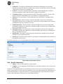
2.0 Product Description
The Orbit MCR and ECR are rugged networking routers providing comprehensive solutions for
IP/Ethernet, serial and machine-to-machine wireless communication.
2.1 Key Features
MCR units include the following key features:
Security—The unit uses industry-leading security features to protect data while maintaining
compatibility with deployed infrastructures. Features include AAA user access with passwords and
lockout protection, VPN (IPSec), signed firmware, secure booting, integrity management and more.
NOTE The Orbit MCR device is designed for high security environments. As such, management of the
device does not support Telnet, but instead implements the more secure SSH protocol.
Small Form Factor—The unit is housed in a rugged enclosure suited for operation in harsh
industrial environments. It requires only protection from direct exposure to the weather and may be
easily mounted inside a NEMA enclosure for outdoor applications when required.
Network Interfaces—Several network interfaces are present to provide connectivity for a variety of
equipment and applications. Ethernet, serial and WiFi interfaces provide local connections while a
cellular interface provides access to public carrier networks.
User Interface—Multiple user interfaces are provided for configuration and monitoring of the unit.
These include local serial console, web, SSH and USB.
NOTE When the unit is installed in hazardous locations, use only the serial or Ethernet connections on
the unit’s front panel. Do not use the USB port in hazardous locations.
Network Management System— Orbit MCR is supported by GE MDS PulseNET, a Network
Management System (NMS), providing monitoring of small and large scale deployment of all GE
MDS devices.
Tamper Detection—The unit contains a 3-axis magnetometer that can be used to detect changes to
the unit’s physical environment after installation and generate notification of the change if it exceeds
configurable thresholds. See “Tamper Detection” on Page 171.
2.2 Interface Types
ECR units are provide external interfaces 1 Ethernet, 1 Serial and 1 USB.
MCR units are offered in two external interface offerings; 2 Ethernet/1 Serial (2E1S), or 2 Serial/1
Ethernet (2S1E). However, most information applies equally to both configurations.
2.3 Network Interface Cards (NICs)
2.3.1 4G LTE/CDMA (Verizon Only)
The 4G LTE module is capable of operation on the Verizon Wireless LTE/CDMA network (LTE 700
MHz Band 13) in the United States. The unit supports routing of TCP/UDP/IP data from the Cellular
WAN network interface to any of the other network interfaces using the IPsec VPN or network address
and port translation (NAPT) feature and to a serial port using the terminal server service. The
configuration of these use cases is specified in respective sections on VPN, Firewall and NAT and
Terminal Service.
Orbit MCR with this modem is certified for operation on Verizon Wireless LTE/CDMA (1xRTT/EVDO)
network (ODI certified) in the United States. In addition it is also certified for use with Verizon Wireless
Private Network service (PN Compliant). For more information, refer to “ APPENDIX E – Obtaining
Provisioned 4G/LTE Service (Verizon)” on Page 397.
18
MDS Orbit MCR/ECR Technical Manual
MDS 05-6632A01, Rev. E
The cellular modem inside the unit supports main (primary) and secondary antenna (for receive diversity).
The primary antenna must be installed for cell modem to register with the cellular network. It is strongly
recommended that a secondary antenna be installed for achieving a robust cellular link.
This 4G modem supports following technologies:
LTE 1900(B2), AWS (B4), 850(B5), 700 (B13), 700(B17), 1900(B25)
CDMA 1xRTT/EV-DO Rev A - 800(BC0), 1900(BC1), 800(BC10)
Orbit MCR with this modem is Verizon ODI certified for operation on 4G LTE/3G CDMA networks, in
North America - with Verizon Wireless. Orbit MCR is also compliant with Verizon Private Network
2.3.2 4G LTE, HSPA+, GSM/GPRS (EMEA/APAC)
This 4G modem supports following technologies:
LTE 2100(B1), 1800(B3), 2600(B7), 900(B8), 800(B20) MHz
GSM/GPRS/EDGE 850/900/1800/1900 MHz
UMTS/HSPA/HSPA+ 2100(B1), 1900(B2), 850(B5), 900(B8) MHz
Orbit MCR with this modem is GCF certified for operation on 4GLTE/3G GSM/UMTS networks,
primarily in EMEA and APAC countries.
2.3.3 4G LTE, HSPA+, GSM/GPRS (North America)
This 4G modem supports following technologies:
LTE 1900(B2), AWS (B4), 850(B5), 700 (B13), 700(B17), 1900(B25)
GSM/GPRS/EDGE 850/900/1800/1900 MHz
UMTS/HSPA/HSPA+ 2100(B1), 1900(B2), AWS (B4), 850(B5), 900(B8) MHz
Orbit MCR with this modem is PTCRB certified for operation on 4GLTE/3G GSM/UMTS networks,
primarily in North America - US and Canada.
This modem is also certified for operation on Verizon and Sprint networks in North America.
2.3.4 3G Cell
The 3G modem supports following technologies:
GSM/GPRS/EDGE 850/900/1800/1900 MHz
UMTS/HSPA/HSPA+ 800/850, 900, AWS1700, 1900, 2100 MHz
Orbit MCR with this modem is PTCRB and GCF certified for operation on 2G/3G GSM/UMTS networks
around the world. This modem is also certified for operation on AT&T networks in North America.
2.3.5 900 MHz Unlicensed
900 MHz unlicensed operation is provided by the NX915 module. The NX915 provides long-distance
communications with data rates ranging from 125 kbps to 1.25 Mbps, suitable to interface both Ethernet
and Serial controllers such as PLCs, RTUs and SCADA systems. The NX915 NIC utilizes a combination
of FHSS (Frequency Hopping Spread Spectrum), DTS (Digital Transmission System) and hybrid
FHSS/DTS technologies to provide dependable wireless communications.
Key Benefits
Multiple data rates to meet application range and link budget: 125 kbps, 250 kbps, 500 kbps, 1000
kbps, 1250 kbps
Up to 60 miles LOS (Line of Sight)
Single unit AP, Remote, or Store and Forward
MDS 05-6632A01, Rev. E
MDS Orbit MCR/ECR Technical Manual
19
Patent pending extremely low latency and robust proprietary Media Access Control specifically
designed for 900 MHz communications
High Reliability
- Error detection and re-transmit on error for Unicast traffic
- Repeat support for Multicast/Broadcast traffic
- Interference avoidance will not carelessly send data if a particular frequency cannot support
communications because of interference. Communications deferred until frequency becomes
available or network moves to a new frequency
Ability to skip frequency zones, useful for persistent interferes or co-located networks
Fragmentation support to minimize on-air time in noisy environments
Ad-hoc network discovery with multiple synchronization methods
Fast mode for minimizing synchronization times
Auto mode for discovering network modulation and optimal paths based on statistical analysis of the
network
Store and Forward
- Supports up to 8-hops SAF level depth.
- Supports multiple SAFs on any level.
- Automatically adjusts Media Access scheme for SAF network to support simultaneous
communications at alternating levels and minimize latency, using dynamic fragmentation.
- Supports dynamic and static paths providing flexibility in designing the wireless network.
Quality of Service (QoS)
- Priority Queues
- Source/Destination port and addresses
- Protocol (UDP, TCP, etc.)
2.3.6 Licensed Narrowband
Licensed Narrowband operation is provided by the LN series NIC modules. Licensed Narrowband
modules provide robust long-distance communication in channel bandwidth sizes of 6.25KHz, 12.5KHz,
and 25KHz using QAM technology. Depending on bandwidth, raw data rates range from 20kbps to
120kbps. LN modules provide long-distance communications suitable to interface both Ethernet and
Serial controllers such as PLCs, RTUs and SCADA systems.
Key Benefits
Bi-Directional Adaptive QAM Modulation (QPSK, 16QAM, 64QSM)
Up to 50 miles LOS (Line of Sight)
Single unit AP or Remote
Low latency and robust proprietary Media Access Control specifically designed narrowband
communications
High Reliability
- Error detection and re-transmit on error for Unicast traffic
- Multiple Forward Error Correction (FEC) modes including adaptive FEC
20
MDS Orbit MCR/ECR Technical Manual
MDS 05-6632A01, Rev. E
Quality of Service (QoS)
- Priority Queues
- Source/Destination port and addresses
- Protocol (UDP, TCP, etc.)
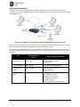
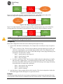
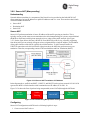
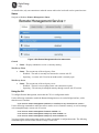
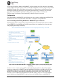
2.4 Typical Applications
The unit provides flexibility in network communications and may be used in a wide variety of
applications. In one common scenario, it provides cellular connectivity to locally-connected devices that
are located on a local/internal/private LAN or WiFi network. The unit acts as an Access Point on the WiFi
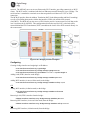
interface to provide connectivity to WiFi clients. Figure 2-1 shows an example network in which the unit
provides connectivity to multiple end devices. The end devices are connected via Ethernet, serial and
WiFi links.
Figure 2-1. Typical MCR Application
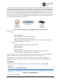
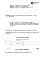
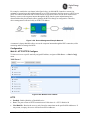
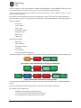
2.5 MCR and ECR Connectors and Indicators
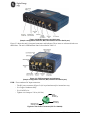
Figure 2-2 shows the unit’s front panel connectors and indicators. These items are referenced in the text
that follows. The unit’s LED Indicator Panel is described in Table 2-5.
.
MDS 05-6632A01, Rev. E
MDS Orbit MCR/ECR Technical Manual
21
Figure 2-2. MCR Connectors and Indicators
(Sample configuration with Cell, WiFi, two Ethernet and one Serial port)
Figure 2-3 shows the unit’s front panel connectors and indicators. These items are referenced in the text
that follows. The unit’s LED Indicator Panel is described in Table 2-5.
Figure 2-3. ECR Connectors and Indicators
(Sample configuration with Cell, WiFi, Ethernet and Serial port)
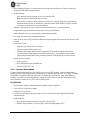
PWR—Two-conductor DC input connection .
- The DC power connector (Figure 2-4) is keyed and can only be inserted one way.
- Use Copper Conductors Only
- Use 18 AWG wire
- Tighten wire clamps to 5 lb-in. (0.6 Nm)
Lea d
Binding
Sc rew s ( 2)
W ire Port s (2 )
(Polarity: Left +, Right –)
Ret aining
Sc rew s (2 )
Figure 2-4. DC Power Connector (P/N 73-1194A39)
22
MDS Orbit MCR/ECR Technical Manual
MDS 05-6632A01, Rev. E
NOTE The unit is designed for use in negative ground DC power systems only. Only use the power
supply provided by the manufacturer for the product or a certified LPS power supply rated 1060 VDC, 4.5 A maximum must be used. Otherwise, safety of the product may be impaired. In
case of doubt, please consult the local authorized suppliers.
Input voltage to the unit must be well filtered and within the range of 10-60 VDC. The maximum rated
power consumption of the device is 15 watts, but actual power may be much less, depending on
configuration. The power supply must be capable of supplying the expected maximum power for the
installation. For expected power requirements in common configurations, see “Technical Specifications”
on Page 363.
ETH1 / ETH2— Ethernet connection port. These ports support both device management and payload
data transport. Depending on ordered options, the unit may have one or two Ethernet ports. This is a
standard RJ-45 jack and features MDIX auto-sensing capability, allowing straight-through or crossover
cables to be used.
Connecting to the unit via SSH supports device management and provides the same user interface
available using the unit’s COM1 serial port. Various options are available for passing Ethernet data,
allowing system administrators to optimize the configuration for maximum efficiency, based on the
system’s operating characteristics.
(As viewed from the outside the unit)
Table 2-1. ETH1/2 Pin Details
Pin
Function
Pin
Function
1
Transmit Data (TX) High
5
Unused
2
Transmit Data (TX) Low
6
Receive Data (RX) Low
3
Receive Data (RX) High
7
Unused
4
Unused
8
Unused
USB Port—This port allows for connection of a laptop or PC. The port provides a local console for
management of the device. A standard host-to-mini device USB 2.0 cable may be used.
COM1/COM2 Port—This connector serves as the serial interface port for both console management and
payload data. Depending on ordered options, the unit may have one or two COM ports. By default, the
port is enabled for local console control. The COM port serves as the primary interface for connecting the
unit to an external DTE serial device supporting RS-232 or RS-485. If necessary, an adapter may be used
to convert the unit’s RJ-45 serial jack to a DB-9F type (GE MDS 73-2434A12).
NOTE Not all PCs include a serial port. If one is not available, the unit’s USB port may be used to
access the device management interface. Alternatively, a PC’s USB port may be used with a
USB-to-Serial adapter and appropriate driver software. These devices are available from several
manufacturers. A video covering USB driver installation may be accessed from the following
link: http://tinyurl.com/pey2ull
The COM port supports a serial data rate of 1200-230400 bps (115200 default, asynchronous only). The
unit is hardwired as a DCE device. Supported data formats for the COM port are:
8N1 - 8 char bits, no parity, 1 stop bit (Default setting)
8N2 - 8 char bits, no parity, 2 stop bits
MDS 05-6632A01, Rev. E
MDS Orbit MCR/ECR Technical Manual
23
8O1 - 8 char bits, odd parity, 1 stop bit
8O2 - 8 char bits, odd parity, 2 stop bits
8E1 - 8 char bits, even parity, 1 stop bit
8E2 - 8 char bits, even parity, 2 stop bits
7N1 - 7 char bits, no parity, 1 stop bit
7N2 - 7 char bits, no parity, 2 stop bits
7O1 - 7 char bits, odd parity, 1 stop bit
7O2 - 7 char bits, odd parity, 2 stop bits
7E1 - 7 char bits, even parity, 1 stop bit
7E2 - 7 char bits, even parity, 2 stop bits.
The tables on the following page provide pin descriptions for the COM1 data port in RS-232 mode and
RS-485 modes, respectively.
NOTE The COM2 port, if present, is restricted to RS-232 mode; it cannot be used for RS-485.
(As viewed from the outside the unit)
Table 2-2. COM1/2 Port Pin Details (RS-232)
24
Pin
Number
Input / Output
Pin Description
1
Reserved
COM1 only: ALARM Output (refer to “Alarms” on Page 147 )
2
OUT
DCD (Data Carrier Detect)
3
Reserved
--
4
Ground
Connects to ground (negative supply potential) on chassis
5
OUT
RXD (Received Data)—Supplies received data to the connected device
6
IN
TXD (Transmitted Data)—Accepts TX data from the connected device
7
OUT
CTS (Clear to Send)
8
IN
RTS (Request to Send)
MDS Orbit MCR/ECR Technical Manual
MDS 05-6632A01, Rev. E
Table 2-3. COM1 Port Pin Details (RS-485)
Pin
Number
Input/Output
Pin Description
1
Reserved
ALARM Output (refer to “Alarms” on Page 147)
2
OUT
DCD (Data Carrier Detect)
3
Reserved
--
4
Ground
Connects to ground (negative supply potential) on chassis
5
OUT
TXD+/TXB (Transmitted Data +)—Non-inverting driver output. Supplies
received payload data to the connected device.
6
IN
RXD+/RXB (Received Data +) — Non-inverting receiver input. Accepts
payload data from the connected device.
7
OUT
TXD-/TXA (Transmitted Data -)—Inverting driver output. Supplies
received payload data to the connected device.
8
IN
RXD-/RXA (Received Data -) — Inverting receiver input. Accepts
payload data from the connected device.
COM1 Port notes and wiring arrangements (for RS-485)
The COM1 port supports 4-wire and 2-wire RS-485 mode as follows:
-
RXD+ / RXB and RXD– / RXA are data sent into the unit
RXD+ / RXB is positive with respect to RXD– / RXA when the line input is a “0”
TXD+ / TXB and TXD– / TXA are data sent out by the unit
TXD+ / TXB is positive with respect to the TXD– / TXA when the line output is a “0”
2-wire RS-485 mode connections:
- Connect pins 5&6 (TXD+/RXD+) together and connect to (TXD+/RXD+) tied together on
connected device
- Connect pins 7&8 (RXD-/TXD-) together and connect to (TXD-/RXD-) tied together on
connected device
4-wire RS-485 mode connections:
-
Connect pin 5 (TXD+) to RXD+ of connected device
Connect pin 6 (RXD+) to TXD+ of connected device
Connect pin 7 (TXD-) to RXD- of connected device
Connect pin 8 (RXD-) to TXD- of connected device
Figure 2-5 illustrates the 2-wire and 4-wire connections described above.
Figure 2-5. EIA-485 4-Wire/2-Wire Connections
MDS 05-6632A01, Rev. E
MDS Orbit MCR/ECR Technical Manual
25
NOTE GE MDS part number 73-2434A25 provides a custom RJ45 to DB9 Adapter for use with the
Orbit MCR and other GE MDS products. The chart below provides details for connections
made using this adapter.
WIRING CHART
RJ-45 PIN
1
2
3
4
5
6
7
8
FUNCTION
DSR
DCD
DTR
GND
RXD
TXD
CTS
RTS
DB9 PIN
6
1
4
5
2
3
8
7
LED Status Indicators—The LEDs on the unit provide visual indications of the status of the device as
shown in the following chart:
Figure 2-6. LED Status Indicators
Table 2-4. Description of LED Status Indicators
LED Name
LED State
Description
PWR
(DC Power)
Off
Solid Green
Fast Blink/Red (1x/sec.)
No power to unit
Unit is powered, no problems detected
Alarm indication
ETH
(Ethernet)
Off
Solid Green
Blinking Green
No Ethernet link to network
Ethernet link present
Ethernet traffic in/out
COM
(Serial Comm. Port)
Off
Blinking Green
No serial connection, or idle
Serial traffic in/out
NIC1
Off
Solid Green
Interface disabled
Interface enabled
NIC2
Off
Solid Green
Interface disabled
Interface enabled
NOTE In addition to the LEDs above, the Ethernet connector has two embedded LEDs. A yellow
indicates a link at 100 Mbps operation. A flashing green indicates Ethernet data traffic.
26
MDS Orbit MCR/ECR Technical Manual
MDS 05-6632A01, Rev. E
Depending on the interfaces ordered, the NIC1 and NIC2 slot can be populated with a Cellular modem, a
WiFi interface, LnRadio interface, or an NxRadio interface. Described in Table 2-5 and Table 2-6 below,
are the possible NIC1 and NIC2 LED combinations based on the product configuration ordered.
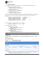
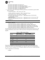
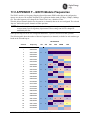
Table 2-5. MCR NIC LED Descriptions
Product Configuration
NIC1
NIC2
MCR-4G + WiFi
Cellular
WiFi
MCR-4G Only
Cellular
Off
MCR-3G + WiFi
Cellular
WiFi
MCR-3G Only
Cellular
Off
MCR-WiFi only
Off
WiFi
MCR-900 + 4G
Cellular
900 ISM (NxRadio)
MCR-900 + WiFi
WiFi
900 ISM (NxRadio)
MCR-900 + 3G
Cellular
900 ISM (NxRadio)
MCR-900 Only
Off
900 ISM (NxRadio)
MCR-LN + 3G
Cellular
Lic. Narrowband (LnRadio)
MCR-LN + WiFi
WiFi
Lic. Narrowband (LnRadio)
MCR-LN + 3G
Cellular
Lic. Narrowband (LnRadio)
MCR-LN Only
Off
Lic. Narrowband (LnRadio)
Table 2-6. ECR NIC LED Descriptions
Product Configuration
NIC1
NIC2
ECR-4G + WiFi
Cellular
WiFi
ECR-4G Only
Cellular
Off
ECR-3G + WiFi
Cellular
WiFi
ECR-3G Only
Cellular
Off
ECR-WiFi only
Off
WiFi
ECR-900 + WiFi
WiFi
900 ISM (NxRadio)
ECR-900 Only
Off
900 ISM (NxRadio)
ECR-LN + WiFi
WiFi
Lic. Narrowband (LnRadio)
ECR-LN Only
Off
Lic. Narrowband (LnRadio)
2.6 Grounding Considerations
To minimize the chance of damage to the unit and its connected equipment, a safety ground (NEC Class 2
compliant) is recommended, which bonds the chassis, antenna system(s), power supply and connected
data equipment to a single-point ground, keeping all ground leads as short as possible.
Normally, the unit is adequately grounded if mounted with the flat brackets to a well-grounded metal
surface. If the unit is not mounted to a grounded surface, it is recommended that a safety ground wire be
MDS 05-6632A01, Rev. E
MDS Orbit MCR/ECR Technical Manual
27
attached to the screw provided on the bottom corner of the enclosure, in the recessed flat area.
Alternatively, a safety ground wire may be attached to one of the mounting bracket screws.
The use of a lightning protector is recommended where the antenna cable enters the building; Bond the
protector to the tower ground, if possible. All grounds and cabling must comply with applicable codes
and regulations. One source for lightning protection products may be found online at
http://www.protectiongroup.com/PolyPhaser.
2.7 Mounting Options
The unit may be mounted with flat mounting brackets or an optional 35 mm DIN rail attachment. Figure
2-7 shows the mounting dimensions for a unit equipped with flat mounting brackets.
Figure 2-7. MCR Flat Mounting Bracket Dimensions
NOTE To prevent moisture from entering the unit, do not mount the case with the cable connectors
pointing up. Also, dress all cables to prevent moisture from running along the cables and into
the unit.
2.7.1 Optional DIN Rail Mounting
If ordered with the DIN rail mounting option, the unit is supplied with a DIN rail clip attached to the case.
The integrated bracket on the unit’s case allows for quick installation and removal from a DIN mounting
rail as shown in Figure 2-8.
Figure 2-8. DIN Rail Attachment and Removal
(Pull down tab to release from rail)
28
MDS Orbit MCR/ECR Technical Manual
MDS 05-6632A01, Rev. E
2.8 Antenna Planning and Installation
Consideration must be taken to select appropriate antennas for optimal RF performance. This section
reviews the key factors involved in selecting and installing antennas for the Orbit MCR and ECR. Only
approved antennas may be used on the unit’s RF output connectors. These antennas are listed in each
applicable section for each RF type. The use of non-approved antennas may result in a violation of FCC
rules and subject the user to FCC enforcement action.
Cell Antennas (Aux and Main)—These SMA coaxial connectors are for attachment of cellular antennas.
The MAIN connection is for basic cellular transmission/reception and the AUX connector is for
attachment of a receive-only antenna which provides MIMO receive operation (diversity) with standard
Cell modules, improving signal quality in many installations. In general, both antennas should always be
used for cellular operation. The GE MDS part number for this antenna type is 97-2485A04.
Figure 2-9. Directly-Connected Cellular Antenna (Typical Style)
(GE MDS Part No. 97-2485A04)
WiFi Antenna—Antenna connection for 2.4 GHz WiFi service. The connector appears similar to the
cellular connectors discussed above, but is a Reverse-SMA type. It contains a pin that matches with an
SMA-F connector. The GE MDS part number for this antenna is 97-4278A34.
To connect an external WiFi antenna, 97-4278A48, a Reverse SMA to N-Female cable and antenna
mount is required. These are not sold from GE MDS but are available from many retailers.
900 MHz ISM Antennas —Antenna connection is a TNC connector. Multiple options are available for
this unlicensed operation.
NOTE For 900MHz ISM operation (NX915 NIC) professional installation is required.
NOTE For Australia and New Zealand the maximum EIRP must be limited to 30 dBm. If ((antenna
gain - feed line loss) + power output setting) > 30), then
the power output of the
NX915 must be reduced.
NOTE For regions governed by FCC/IC compliance the maximum EIRP must be limited to 36 dBm. If
((antenna gain - feed line loss) + power output setting) >36), then the power
output of the NX915 must be reduced.
Licensed Narrowband Antennas —Antenna connection is a TNC connector. Multiple options are
available based on radio type and site-specific licensing rules.
MDS 05-6632A01, Rev. E
MDS Orbit MCR/ECR Technical Manual
29
Antenna Type and Orientation (Cell & Wi-Fi)
It is important to use antennas designed to operate in the applicable cellular coverage bands with a Return
Loss of 10 dB or better. Placement of the antennas also plays a key role in the coverage of the system.
While the antennas can be placed directly on the face of the unit in some short range installations, the best
performance is obtained when mounting antennas remotely using low loss coaxial cable. Antennas
mounted in close proximity to each other can couple signals between them and desensitize the RF
module.
When placing the indoor SMA style “paddle” antennas on the face of the unit, position them with a 90
degree angle of separation to improve the isolation. A “V” or an “L” configuration is a common approach
to use with the Main channel typically mounted for vertical polarization. The multipath nature of Cellular
systems means that polarization for indoor use is not normally a critical factor. Isolation between the
antennas is more important.
Note that with any installation, there needs to be a minimum 20 cm spacing between all transmit antennas
to avoid co-location difficulties.
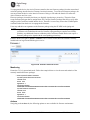
Indoor use case:
This scenario employs direct mounting of an LTE paddle antenna (GE MDS PN: 97-2485A04) on the
Main and Aux Cell channels and cabled mounting of the Wi-Fi antenna (GE MDS PN: 97-4278A34)
using a magnetic mount (GE MDS PN: 97-4278A78). This configuration offers easy mobility for
evaluation purposes or indoor applications with good cellular signal coverage (see Figure 2-10).
Figure 2-10. Direct Mounting of Cell Antenna; Cabled WiFi Antenna
Minimum 8-inch (20.32 cm) separation between cell and WiFi antennas
This arrangement employs cabled mounting of the LTE paddle antennas (GE MDS 97-2485A04) on the
Main and AUX Cell channels and cabled mounting of the Wi-Fi antenna (GE MDS 97-4278A34) using a
magnetic mount (GE MDS 97-4278A78). The Wi-Fi antenna may also be directly attached to the unit, if
desired. This configuration works well for indoor installations in equipment closets, or for more
permanent applications.
Outdoor use case:
External enclosures—If the system is going to be installed in a weathertight enclosure and mounted
outside in the elements, cabled use of external LTE antennas (GE MDS PN: 97-2485A05) on the Main
and AUX Cell ports, with cabled use of the External Wi-Fi antenna (GE MDS PN: 97-4278A48) is a
good solution. This configuration requires a suitable metallic ground plane for the Cellular antennas (8"
diameter disc minimum for the 97-2485A05 series) or a suitable counterpoise for frequencies as low as
698 MHz Metal enclosures work well for ground plane requirements, when ground contact inside the box
is not impeded by painted surfaces.
Do not use internally mounted antennas inside of metal enclosures.
Other antenna configurations can be easily customized for applications not listed here. Consult your
factory representative for installation matters.
30
MDS Orbit MCR/ECR Technical Manual
MDS 05-6632A01, Rev. E
Antenna Installation Guidance (Licensed Narrowband)
Antennas:
LN4 transceivers may be used with a number of different antennas. The exact style and gain factor
depend on regulatory constraints and the physical size/layout of your system. Connection is made to the
radio via a TNC coaxial connector. A directional Yagi (Figure 2-11) or corner reflector antenna is
generally used at remote sites to minimize interference to and from other users. Antennas of this type are
available from several manufacturers, including GE MDS. Contact your sales representative for details.
Figure 2-11. Typical Yagi Antenna (mounted to mast)
Feedlines:
Selection of an antenna feedline is very important. Poor quality cable should be avoided as it will result in
power losses that may reduce the range and reliability of the radio system. The tables which follow show
the approximate losses that will occur when using various lengths and types of coaxial cable. Regardless
of the type used, the cable should be kept as short as possible to minimize signal loss.
Table 2-7. Signal Loss In Coaxial Cables (at 400 MHz)
Cable Type
10 Feet
(3 Meters)
50 Feet
(15 Meters)
100 Feet
(30.5 Meters)
200 Feet
(61 Meters)
RG-8A/U
0.51 dB
2.53 dB
5.07 dB
10.14 dB
½ inch HELIAX
0.12 dB
0.76 dB
1.51 dB
3.02 dB
7/6 inch HELIAX
0.08 dB
0.42 dB
0.83 dB
1.66 dB
1-1/4 inch HELIAX
0.06 dB
0.31 dB
0.62 dB
1.24 dB
1-5/8 inch HELIAX
0.05 dB
0.26 dB
0.52 dB
1.04 dB
MDS 05-6632A01, Rev. E
MDS Orbit MCR/ECR Technical Manual
31
Accessories and Spares
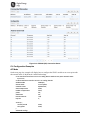
The table below lists common accessories and spare items for use with the MCR. GE MDS also offers an
Accessories Selection Guide listing an array of additional items that may be used with the product.
Contact your factory representative or visit www.gemds.com to obtain a copy of the guide.
Table 2-8. Accessories & Ancillary Items
Item
32
Description
Part Number
DC Power Plug, 2-pin, polarized
Mates with power connector on the
unit’s case. Screw terminals are
provided for wires, threaded locking
screws to prevent accidental
disconnect.
73-1194A53
Setup Guide
(for installation instructions)
Describes the installation and setup
of the unit. It is a companion to this
Technical Manual. PDF copy
available free at www.gemds.com.
05-6709A01
Flat Mounting Bracket Kit
Brackets that attach to the bottom
of the unit, used for mounting to a
flat mounting surface.
03-4123A14
COM Port Adapter
Converts the unit’s RJ-45 serial jack
to a DB-9F type.
73-2434A25
Mini USB 2.0 Cable, 3 ft
USB Type A (M) to mini-USB Type
B (M) cable to provide console
access through the radio’s mini
USB connector.
97-6694A05
DIN Rail Mounting Kit
Hardware for DIN Rail Mounting
03-4125A06
MDS Orbit MCR/ECR Technical Manual
MDS 05-6632A01, Rev. E
MDS 05-6632A01, Rev. E
MDS Orbit MCR/ECR Technical Manual
33
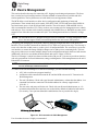
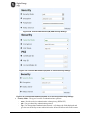
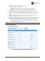
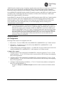
3.0 Device Management
This section describes the steps for connecting a PC, logging in and setting unit parameters. The focus
here is on the local serial console interface, but other methods of connection are available and offer
similar capabilities. The key differences are with initial access and appearance of data.
The MCR offers several interfaces to allow device configuration and monitoring of status and
performance. These include local serial console, USB, NETCONF, HTTPS and Secure Shell (SSH) for
local and remote access via the WAN and LAN networks. The serial console, USB and SSH services
offer a command line interface (CLI). There are three user accounts/roles for management access: admin,
tech and oper. User accounts can be centrally managed with a RADIUS server. RADIUS accounts can be
mapped to one of the three user accounts/roles (See “User Management and Access Controls” on Page
158).
NOTE The Orbit MCR device is designed for high security environments. As such, management of the
device does not support Telnet, but instead implements the more secure SSH protocol.
Configuring and managing the Orbit MCR is done by changing configuration data via the Web User
Interface (UI) or from the Command Line Interface (CLI). Either way requires two steps. The first step is
to use a user interface to add, remove, or alter a piece of configuration data. The second step is to use the
user interface to commit the change. Multiple changes can be made prior to committing them. This twostep process allows users to make multiple changes to the configuration and apply them in a bulk commit.
Additionally, the device can validate the bulk commit and reject it if there is an error.
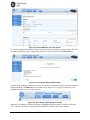
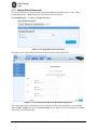
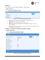
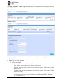
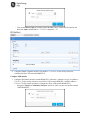
The Device Manager is a built-in software tool that works with your PC’s browser to provide an intuitive,
web-style presentation of all unit information, settings, and diagnostics. Web management uses the unit’s
Ethernet RJ-45 connector
NOTE For security, web access can be enabled/disabled via the CLI using the command: % set
services web http(s) enabled true/false
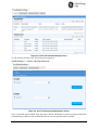
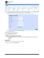
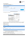
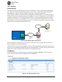
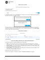
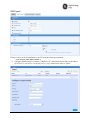
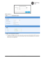
To connect to the unit and manage it via the Device Manager, you will need the following:
A PC with a web browser program installed.
An Ethernet cable connected between the PC and the MCR as shown in PC Connection for
Web Management.
The unit’s IP address. Check with your Network Administrator, or determine the address via a
command line interface connection. The default address for a factory supplied unit is
192.168.1.1.
The user name and password for the unit. Check with your Network Administrator, or, if a
username and password have not been set, use the factory defaults of admin for both entries.
(For security, a new password should be established as soon as possible after login.)
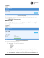
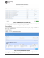
Figure 3-1. PC Connection for Web Management
Use of a modern browser is highly recommended.
34
MDS Orbit MCR/ECR Technical Manual
MDS 05-6632A01, Rev. E
Table 3-1. Browser Support
Browser Type
Version
Microsoft ™ Internet Explorer
9.x or newer
Mozilla Firefox
Mozilla Firefox
Apple Safari (Mac OS X only)
Apple Safari (Mac OS X only)
Google Chrome
26.x or newer
Logging On
1. Connect the unit to a PC via an Ethernet connection.
2. Configure your PC network settings to an IP address on the same subnet as the unit. The default
subnet mask is 255.255.255.0.
NOTE For IP addressing the Orbit MCR uses a routing prefix expressed in CIDR notation instead of
the specifying a subnet mask. The CIDR notation is the first address of a network, followed by
a slash character (/), and ending with the bit-length (max 32) of the prefix. A subnet mask is
expressed in dot-decimal notation. For example, 192.168.1.0/24 is equivalent to specifying
192.168.1.0 with a subnet mask of 255.255.255.0.
3. Enter the unit’s IP address in a web browser window, just as you would enter a website address.
When the login screen appears (Figure 3-2. Login Screen), enter the User Name and Password for
the unit. The default entries for a new unit are both admin. Click OK.
Figure 3-2. Login Screen
Getting an Overview of Unit Settings
To get a top-level view of the key settings and operating parameters for the unit, select Home in the upper
left hand side of the screen and a summary screen will be displayed. When finished, log out of the Device
Manager by clicking Logout in the upper right hand side of the screen.
MDS 05-6632A01, Rev. E
MDS Orbit MCR/ECR Technical Manual
35
Figure 3-3. Device Manager, Overview Screen
For initial configuration, the Setup Wizard will appear and provide guidance in typical setups. This will
be disabled after initial setup is completed, but may be re-run at any time from the Wizards page.
Figure 3-4. Initial Setup Wizard Starting Page
From the Web UI changes made on the screens are not saved or implemented until via the save button or
commit command. The Save button in the banner on the top left of every page. Normally this is not
highlighted and blue in color as shown below:
Figure 3-5. Save Button—No changes to commit
When there are changes to commit, the button is highlighted and colored green. Options available are:
View, Validate and Cancel. Clicking the button defaults to Validate and saves the changes.
36
MDS Orbit MCR/ECR Technical Manual
MDS 05-6632A01, Rev. E
Figure 3-6. Save Button—Changes to commit
From the CLI, all changes are made and committed using by using the commit command and enter.
% commit
3.1 Initial Settings Overview
3.1.1 Setting Basic Parameters—First Steps
There are three tasks that should be performed after initial startup and connection to a PC, as follows:
1. Create One-Time Programmable passwords for device recovery in the event a password is lost.
2. Change the login passwords.
3. Evaluate the default factory configuration and set it to the user's required security level.
3.1.2 One-Time “Recovery” Passwords
The MDS Orbit platform employs extensive security measures to prevent unauthorized access. As such,
there are no hidden manufacturer passwords or other “back doors” found in less secure products. If a
password is lost, there is no way to access the unit, except by using a one-time password (OTP) for
recovery. This must be established by the user beforehand. Without a one-time password, the unit will not
be accessible and the hardware will need to be returned to the factory to be re-imaged to defaults.
Technical Support will not be able to assist you if a password is lost, so creating a one-time password is
strongly encouraged. A device with a lost password
Refer to instructional video:
https://www.youtube.com/watch?v=qHiFg-QZP_Q&list=UUWEcxa9_FSdEqowzxNbNLsw&index=35
Associated QR Code:
One-Time Passwords: How They Work
One-time recovery passwords put control directly and exclusively in the user’s hands. They are similar to
spare keys for a lock. If you make a spare key and put it away safely, you can take it out to quickly gain
entry when your primary key is lost. If you don’t make a spare, you are always at risk of locking yourself
out.
A one-time recovery password is different from the one used to log into the unit on a routine basis. It is
only for use when the primary password is lost or forgotten. When a one-time password is used to log in,
that password is automatically revoked from the list of passwords created. You may create up to five onetime passwords at one time and more can be created if some get used. A password cannot be used again
for log in to the unit, hence the name “one-time” password.
NOTE One-time passwords are only displayed at the time of creation. The password must be saved and
archived at that time. There is no way to view this password again.
MDS 05-6632A01, Rev. E
MDS Orbit MCR/ECR Technical Manual
37
Figure 3-7. One-Time Password Add in Setup Wizard
Logging in With a One-Time Password
Logging in with a one-time password can only be performed from the local serial or USB console. You
cannot use a one-time password when connecting to the unit remotely. To use the one-time password for
log-in, proceed as follows:
1. At the username prompt, enter the word recovery.
2. At the password prompt, paste in the one-time-password saved earlier on your PC. Using a onetime-password forces the unit to perform the function which was previously defined when the
password was created:
- factory-reset — The unit resets its entire configuration to factory defaults
- login — The unit allows logging in with admin privileges
Special case: If someone has disabled console access on the COM port, the login prompt will still be
present on that console, but only one-time passwords will be accepted. This is done to provide a way to
recover the unit in the case where the COM1 port has been disabled and the unit cannot be accessed via
TCP (for example; SSH).
Deleting a One-Time Password
As noted earlier, a one-time password is automatically revoked when it is used for log-in. A revoked
password may be replaced, but it must first be removed from the list so a new one can be generated. Any
of the five stored passwords may be removed on demand. As long as there is a free slot, an additional
password can be created, up to the maximum number of five. Logs are generated when the user creates,
deletes or logs in with a one-time-password.
Managing One-Time Passwords
One-Time passwords can be created as part of the Initial Setup Wizard, as shown in the example below.
To view currently configured One-Time Passwords, navigate to
Troubleshooting ---> Status / Recovery Information / Passwords
38
MDS Orbit MCR/ECR Technical Manual
MDS 05-6632A01, Rev. E
Figure 3-8. One-Time Password Display Screen
To edit or delete (revoke) a One-Time Password, navigate to:
Troubleshooting ---> Actions / One Time Passwords
Figure 3-9. One Time Passwords Management Screen
Up to 5 passwords may be added. They may also be deleted. Remember to replace a used password which
is automatically revoked. It must be deleted if there are no more password slots available.
MDS 05-6632A01, Rev. E
MDS Orbit MCR/ECR Technical Manual
39
3.1.3 Change Default Passwords
For security purposes it is highly advised to change the default passwords for all user roles. This is
accomplished on the “Change Password” Screen shown below located at:
User Authentication ---> Actions / Change Passwords
Figure 3-10. Change User Password Screen
This feature is also a part of the Initial Setup Wizard, as shown in the Figure below.
Figure 3-11. User Password Initial Setup Wizard Change Screen
The selected password(s) must follow the rules established on the “Password Options” screen located
under the Basic Config tab of the User Authentication section. These rules may be modified to conform
to the local security requirements.
40
MDS Orbit MCR/ECR Technical Manual
MDS 05-6632A01, Rev. E
3.1.4 Security Review
The Orbit MCR provides strong cyber security capabilities that may be customized to meet enterprise
security policy requirements. By default the Orbit MCR is configured with a light level of security. There
are many features and parameters that should be considered and adjusted according to the security policy.
Some of the areas to consider are:
1. User Authentication
- Update factory default passwords.
- Secure login access into Orbit with local or RADIUS based user authentication.
2. Device Management
- Secure access to Orbit for device management by enabling/disabling HTTP/HTTPS/SSH.
- It is recommended that HTTP be disabled.
- It is recommended that SNMPv1/v2c be disabled and SNMPv3 be enabled
3. Static Routing - Limit local broadcast and multicast traffic from being shared with specified
interfaces.
4. Packet Filtering – Prevent ingress/egress of unwanted traffic by configuring firewall/NAT.
5. Secure end-to-end network links using IPsec VPN with pre-shared-key or certificate based setup.
6. Cellular Security – Utilize IPSec VPN to secure end-to-end cellular link over public cellular
networks.
7. WiFi Security – Secure Wi-Fi link with pre-shared key or EAP-TLS/RADIUS using certificates.
8. NX915 Security – Secure 900MHz link pre-shared key or EAP-TLS/RADIUS using certificates.
9. LN Security – Secure Licensed Narrowband link pre-shared key or EAP-TLS/RADIUS using
certificates.
10. Event Logging – Securely send event logs to central SYSLOG server by configuring SYSLOG over
TLS.
11. PKI/Certificate Management – Generate/upload private keys/certifications for use in certificate
based security setup.
12. Tamper Detection – Enable tamper detection to detect unauthorized device enclosure removal and
physical movement from authorized install site.
3.2 Preconfigured Settings
The GE MDS factory configuration establishes typical settings based on the types of modules ordered.
The intent is to provide as much out-of-box functionality as possible. For example, in WiFi/Cell
configurations, the unit is configured as a WiFi hotspot.
The Orbit MCR is highly configurable to meet field requirements, but comes preconfigured as
follows:
- The COM and USB ports are enabled for local console operation.
- When applicable, interfaces are preconfigured as members of a bridge.
- A DHCP server is enabled for WiFi clients and the Ethernet LAN ports.
Units are configured with a set of pre-defined defaults set by the factory.
- Default Ethernet IP address 192.168.1.1
- Firewall/NAT/DNS proxy enabled
- DHCP server enabled
MDS 05-6632A01, Rev. E
MDS Orbit MCR/ECR Technical Manual
41
Other defaults
WiFi (hotspot):
- Set as Access Point (AP)
- SSID = GEMDS_<SERNUM> SERNUM refers to the unit’s serial number, printed on a
chassis sticker.
- The Ethernet ports are bridged with the WiFi AP.
- SSID broadcast enabled
- Security = WPA2-PSK, CCMP with passphrase: GEMDS_ORBIT
Cellular modem:
- 4G Cellular service is enabled with firewall/router rules in place.
- If Verizon 4G, APN is set to vzwinternet with VZW connection profile.
- 3G Cellular service requires carrier-specific configuration.
ISM Unlicensed 900 MHz radio (NX915):
- Radio Mode set to Remote
- Modem Mode 500kbps
- Power at 30 dBm
Licensed Narrowband radio (LN400):
-
Radio Mode set to Remote
Adaptive Modulation enabled
FEC set to low gain
Power at 40 dBm
These configuration settings allow a connection to a PC to the unit via WiFi or the LAN port and access
to the Internet via cellular, if equipped and supported by a suitable service plan.
3.3 Specific Application Examples Using Device Manager
The following examples illustrate the set of steps to configure the MCR for specific scenarios. The “Step”
column is the high level concept, The “Manual Section” provides a link to the manual section that can
explain in more detail and the “Comment...” column provides additional information or specific settings
pertinent to the example. More examples can be found in 05-6909A01 Orbit MCR Cookbook available
ton the GE MDS website.
Initial Setup Example
During the initial configuration of a device the following checklist in Table 3-2 should be consulted to
commission the unit for operation.
Table 3-2. Checklist for Initial Setup/Configuration
Step
Establish connection to
the device (SSH/ Serial/
USB/ Web)
42
Applicable Manual Section
Initial Settings Overview
Specific Application Examples Using Device
Manager
Using the Command Line Interface (CLI)
MDS Orbit MCR/ECR Technical Manual
Comment / Additional
Information
With serial/USB/SSH
interfaces the "Command
Line Interface" (CLI) is
provided.
MDS 05-6632A01, Rev. E
Step
Applicable Manual Section
Comment / Additional
Information
Create One-Time
Programmable
passwords for device
recovery in the event a
password is lost
One-Time “Recovery” Passwords
This is extremely important
for recovering a unit if a
admin password is lost.
Note - this is part of the
Initial Setup Wizard
Change the login
passwords/configure
users
Change Default Passwords
For security purposes it is
highly recommended that
password for all user type
be changed from their
defaults.
Note - this is part of the
Initial Setup Wizard
Review factory default
configuration
Preconfigured Settings
Disable DHCP if using
Static IP Addresses for
WiFi and Ethernet
port(s)
3.8.12 - DHCP Service
Set Date /Time or NTP
Server
3.7.1 - Date, Time and NTP
Note - this is part of the
Initial Setup Wizard
Set Geographic
Location (if desired)
3.7.2- Geographical-location
Note - this is part of the
Initial Setup Wizard
Configure WiFi (if
present)
3.5.3 - WiFi
Configure Cell interface
(if present)
3.5.2 - Cell
10.0 - APPENDIX E – Obtaining
Provisioned 4G/LTE Service (Verizon)
A guide to setting up
cellular service in the listed
Appendix
Configuring for 900MHz
operation (if present)
3.5.4 - Unlicensed 900 MHz ISM (NX915)
NX915 is the hardware
module that provides the
900 MHz operations. It is
factory configured based
on country codes for legal
operations.
Configuring for
Licensed Narrowband
operation (if present)
3.5.5 - Licensed Narrowband (LN)
LNxxx hardware modules
provide operation in
various global frequencies
from 400 MHz to 960 MHz.
User configuration is
required to match
conditions of license.
MDS 05-6632A01, Rev. E
MDS Orbit MCR/ECR Technical Manual
43
Application Example #1
In the figure below, the Orbit MCR is functioning as a WiFi Access Point to provide connectivity
between a set of laptops and a handheld device. The MCR is also acting as a DHCP server for the laptops
and handheld device.
Figure 3-12. Example 1: Unit Providing Laptop and Handheld Device Connectivity
By default the unit is configured in this basic configuration. Refer to Preconfigured Settings for accessing
the unit using the default setting for the Ethernet ports, WiFi and the bridge.
The following chart lists the required steps to configure the MCR for this specific scenario. Note that for
each step the linked manual section is provided as well as detailed information for use in recreating the
example.
Step
44
Applicable Manual
Section
Comment / Additional Information
Configure WiFi
3.5.3 - WiFi
Enable unit as Access Point
Set SSID mysid
Configure network
3.8.4 - Bridging
Add ETH1 and WiFi to the bridge
Set the Bridge IP
address
3.8.4 - Bridging
Set ipv4 address 192.168.1.21
Set prefix-length 24
Configure DHCP
Server
3.8.12 - DHCP Service
Set v4subnet 192.168.1.0/24
Set domain-name gemds
Set range-start 192.168.1.10
Set range-end 192.168.1.19
Set router 192.168.1.1
Set broadcast-address 192.168.1.255
MDS Orbit MCR/ECR Technical Manual
MDS 05-6632A01, Rev. E
Application Example #2
In the figure below, there are two Orbit MCR devices, one acting as a WiFi Access Point, the other as a
WiFi Station. Together, they provide a wireless bridge between the laptop and the SCADA device.
Figure 3-13. Example 2: Units Providing Wireless Bridge Between Laptop & SCADA Device
Step
Applicable Manual Section
Comment / Additional
Information
Orbit MCR #1: Configure
WiFi as an Access Point
3.5.3 - WiFi
Enable Access Point mode
Create SSID of myssid
Orbit MCR #1: Configure to
bridge traffic from ETH1 and
WiFi
3.8.4 - Bridging
Add ETH1 and WiFi to the bridge
Orbit MCR #1: Set bridge IP
address
3.8.4 - Bridging
Set to 192.168.1.21
prefix-length 24
Orbit MCR #1: Enable
DHCP Server on bridge
3.8.12 - DHCP Service
Set v4subnet 192.168.1.0/24
Set domain-name: gemds
Set range-start: 192.168.1.10
Set range-end:192.168.1.19
Set router: 192.168.1.1
Set broadcast-address:
192.168.1.255
Orbit MCR #2: Configure
WiFi as an Station
connecting to Orbit MCR #1
3.5.3 - WiFi
Enable Station mode
Connect to AP SSID of myssid
Orbit MCR #2: Configure to
bridge traffic from ETH1 and
WiFi
3.8.4 - Bridging
Add ETH1 and WiFi to the bridge
Orbit MCR #2: Set bridge IP
address
3.8.4 - Bridging
Set to 192.168.1.22
prefix-length 24
MDS 05-6632A01, Rev. E
MDS Orbit MCR/ECR Technical Manual
45
Application Example #3
The figure below shows the Orbit MCR #2 device acting as a terminal server to provide connectivity to
the serial-based SCADA device via UDP.
Figure 3-14. Example 3: Unit Providing Connectivity to Serial-Based SCADA Device via UDP
NOTE The configuration for Orbit MCR #1 in Example 3: Unit Providing Connectivity to SerialBased SCADA Device via UDP is identical to the configuration shown in the previous example
(Example #2).
Step
Applicable Manual Section
Orbit MCR #1: Configure
WiFi as an Access Point
Enable Access Point mode
Create SSID of myssid
Orbit MCR #1: Configure to
bridge traffic from ETH1 and
WiFi
3.8.4 - Bridging
Orbit MCR #1: Set bridge IP
address
3.8.4 - Bridging
Set to 192.168.1.21
prefix-length 24
3.8.12 - DHCP Service
Set v4subnet 192.168.1.0/24
Set domain-name gemds
Set range-start 192.168.1.10
Set range-end 192.168.1.19
Set router 192.168.1.1
Set broadcast-address
192.168.1.255
Orbit MCR #1: Enable
DHCP Server on bridge
Orbit MCR #2: Configure
WiFi as an Station
connecting to Orbit MCR #1
3.5.3 - WiFi
Add ETH1 and WiFi to the bridge
Enable Station mode
connect to AP SSID of myssid
Orbit MCR #2: Configure to
bridge traffic from ETH1 and
WiFi
3.8.4 - Bridging
Orbit MCR #2: Set bridge IP
address
3.8.4 - Bridging
Set to 192.168.1.22 prefix-length 24
3.8.13 - Terminal Service
Set mode udp
port 30000
remote addr: 192.168.1.11
port 30001
Set up Terminal Server
COM1
46
3.5.3 - WiFi
Comment / Additional Information
MDS Orbit MCR/ECR Technical Manual
Add ETH1 and WiFi to the bridge
MDS 05-6632A01, Rev. E
Application Example #4
In the figure below, an Orbit MCR provides internet access for a laptop that is accessing a public web
page.
Figure 3-15. Example 4: Unit Providing Internet Access for Laptop
SIM Type: In this scenario, the MCR-4G has a SIM card installed that simply provides Internet access.
Step
Applicable Manual Section
Comment / Additional
Information
Add ETH1 to the bridge.
Configure ETH1 to be in
Bridge
3.8.4 - Bridging
Configure Bridge for an
IP address
3.8.4 - Bridging
Enable the firewall for
local address space
3.8.7 - Access Control List (Packet
Filtering / Firewall)
Enable firewall
Configure the incoming
out of network address
to accept only ICMP
3.8.7 - Access Control List (Packet
Filtering / Firewall)
Set Rule 1
protocol ICMP,
Action accept
Configure the incoming
out of network address
to drop all other traffic
(IN_UNTRUSTED)
3.8.7 - Access Control List (Packet
Filtering / Firewall)
Set Rule 10
protocol all,
Action drop
Configure the outgoing
destination to allow
local network
(OUT_UNTRUSTED)
3.8.7 - Access Control List (Packet
Filtering / Firewall)
Set Rule 1
src Address: LOCAL-NETS
Add Interface address; true
Action accept
Configure the outgoing
destination to drop
other network destined
packets
(OUT_UNTRUSTED)
3.8.7 - Access Control List (Packet
Filtering / Firewall)
Set Rule 10
protocol all
Action drop
Enable Firewall NAT to
masquerade
3.8.7 - Access Control List (Packet
Filtering / Firewall)
rule-set: MASQ
Enable Firewall NAT
rule
3.8.8 - Source NAT (Masquerading)
Set Rule 1
source-nat : interface
Enable Cell interface
3.5.2 - Cell
Apply Firewall
IN_UNTRUSTED and
OUT_UNTRUSTED
filters to Cell interface
3.8.7 - Access Control List (Packet
Filtering / Firewall)
Set Cell input filter to
IN_UNTRUSTED
Set Cell output filer to
OUT_UNTRUSTED
Set NAT on Cell
interface to
masquerade
3.8.8 - Source NAT (Masquerading)
Set cell NAT source to MASQ
MDS 05-6632A01, Rev. E
Set address to 192.168.1.1
prefix length 24
MDS Orbit MCR/ECR Technical Manual
47
3.4 Using the Command Line Interface (CLI)
3.4.1 Differences between Serial and SSH
Serial and SSH both present identical management capabilities, but the method of access is different for
each. Serial involves an RS-232 serial connection from a PC to the unit’s COM port. SSH uses an
Ethernet PC connection to the unit’s ETH port. Maximum recommended cable length for a serial
connection is 50 feet (15 meters). SSH can be connected to the unit from any network point that has
connectivity with the PC, including remotely over the Internet, or using other networks.
The focus of these instructions is on Serial access, but SSH may also be used by following these
additional points, which replace Steps 1-3 below:
Connect to the unit with a PC that is in the same IP network as the MCR. Launch an SSH client
program and connect to the unit using its programmed IP address.
The default IP address for the unit is 192.168.1.1. If you do not know the current IP address of the
unit, follow the serial configuration instructions below, where you can determine the address and
continue configuration, or check with your network administrator.
3.4.2 Establishing Communication—Serial Interface
Follow these steps to configure the unit for its first use with serial console interface:
1. Connect a PC to the unit’s COM port as shown in Figure 3-16. Maximum recommended cable
length is 50 ft/15 m.
NOTE Not all PCs include a serial port. If one is not available, the Orbit MCR’s USB port can be used
to access the device management console by using a Mini-USB cable between the device and a
PC. The PC needs to install the device driver.
NOTE If the COM port has been configured for terminal server operation, pressing +++ switches it to
console (management) mode. Serial console mode is required for the following steps.
Launch a terminal communications program, such as HyperTerminal, with the following
communication parameters: 115200 bps (default speed), 8 bits, no parity, one stop bit (8N1) and
flow control disabled. Incorrect parameter settings are a frequent cause of connection difficulties.
Double check to be sure they are correct.
An adapter may be used to convert the unit’s RJ-45 serial jack to a DB-9F type (GE MDS part no.
73-2434A12). If no serial port exist on the PC, a Mini-USB cable may be connected between the
MCR’s USB device port and the PC.
Figure 3-16. PC Connection for Programming/Management
2. Press the ENTER key to receive the Login: prompt. This indicates that the unit is ready to receive
commands.
3. At the Login: prompt, enter admin (lower case) and press ENTER .
48
MDS Orbit MCR/ECR Technical Manual
MDS 05-6632A01, Rev. E
4. If no password has been previously set, enter the default password (admin) and press ENTER ;
otherwise, enter the saved password at the Password: prompt. (Before placing the unit in final
service, it is recommended that the default password be changed to ensure that only authorized
users have access.)
5. After successful login, the command prompt appears where you may configure and manage a
number of unit settings.
3.4.3 Using the CLI
This section describes how to use the CLI by using an example: changing the name of the unit.
Step 1: Login to the device using the serial console and use the default username admin and the default
password admin.
(none) login: admin
Password:
Welcome to the CLI
admin connected from 127.0.0.1 using console on (none)
Step 2: Instruct the device to enter configuration mode by typing configure and pressing the enter key:
> configure
Entering configuration mode private
Step 3: Change the device name by typing in the following, followed by enter: set system name
Device539
% set system name Device539
Step 4: Verify the change looks correct by reading the data back, using the following, followed by the
enter key: show system name
% show system name
name Device539;
Step 5: Commit the change by typing in the following, followed by the enter key: commit
% commit
Commit complete.
Step 6: Exit the configuration mode by typing the following, followed by the enter key: exit
% exit
Step 7: Exit the login session by typing the following, followed by the enter key: exit
> exit
Device539 login:
Tab Completion Feature
Tab-completion is a powerful feature that presents CLI users with assistance while typing. Depending on
the text that was already entered, tab-completion will display different possible completions. When the
tab key is pressed and no text has been entered, the CLI shows all possible commands that can be typed.
Creating a One-Time Password
To create a one-time recovery password, proceed as follows:
Upon successful log-in, enter the following command:
> request system recovery one-time-passwords create function <selected function>
MDS 05-6632A01, Rev. E
MDS Orbit MCR/ECR Technical Manual
49
NOTE A one-time password is automatically generated and displayed on the screen. Copy this
password and save it in the desired location on your PC. There is no way to ever view it again
from the command line console, so be sure it is properly saved.
To create additional one-time passwords (up to a total of five), repeat the step above.
Deleting a One-Time Password
To remove an existing password from the list, proceed as follows:
Enter the command request system recovery one-time-passwords delete identifier X, where X is a number
from the currently available one-time passwords. This identifier is not reused. If all five passwords have
been created, then ID 1 can be deleted and the next created password will be at ID 6.
The current list of passwords may be viewed by issuing the command show system recovery one-timepasswords. The following is an example output from that command. On the unit shown, only two
passwords have been stored. Password 1 or 2 can be deleted from this list.
IDENTIFIER FUNCTION STATUS
DATE CREATED
DATE REVOKED USER
-----------------------------------------------------------------------------------------------------------------------------------------------1
login
usable
2012-06-19T00:27:24+00:00
2
login
usable
2012-06-19T00:27:25+00:00
3.4.4 CLI Quick Reference Table
Table 3-3 provides a summary listing of commonly needed tasks and the appropriate commands to enter.
The table can be used as a quick reference before consulting the more detailed information, which follows
in this section. Each CLI command is preceded by the symbol > for operational command, or % for a
configuration command.
Table 3-3. CLI Quick Reference Table
If you wish to...
50
Enter this CLI command:
Create a one-time password
> request system recovery one-time-password create function
<user function>
View all network interface
status and statistics
> show interfaces-state interface
Create a bridge
% set interfaces interface Bridge type bridge
Add the ETH1 interface to a
bridge
% set interfaces interface Bridge bridge-settings members port
ETH1
Remove the ETH1 interface
from a bridge
% delete interfaces interface Bridge bridge-settings members port
ETH1
Set WiFi AP SSID
% set interfaces interface Wi-Fi wifi-config mode access-point apconfig ap myssid
Enable WiFi WPA2-Personal
security
% set interfaces interface Wi-Fi wifi-config mode access-point apconfig ap myssid privacy-mode wpa2-personal psk-config psk
mypassphrase encryption ccmp
Enable WiFi SSID
Broadcasting
% set interfaces interface Wi-Fi wifi-config ap-config ap myssid
broadcast-ssid true
View Cell Settings
> show configuration interfaces interface Cell cell-config
Monitor Cell Status
> show interfaces-state interface Cell cell-status | repeat 5
View NxRadio Settings
> show configuration interfaces interface NxRadio nx-config
Monitor NxRadio Status
> show interfaces-state interface NxRadio nx-status | repeat 5
View WiFi Settings
> show configuration interfaces interface Wi-Fi wifi-config
MDS Orbit MCR/ECR Technical Manual
MDS 05-6632A01, Rev. E
Table 3-3. CLI Quick Reference Table
If you wish to...
Enter this CLI command:
Monitor WiFi Status
> show interfaces-state interface Wi-Fi wifi-status | repeat 5
View the routing table
> show routing
View the event log
> show table logging event-log
Set the admin user’s
password
> request system authentication change-password user admin
password admin1234
Set the device name
% set system name “Mydevice”
Set the baud rate on COM1
% set services serial ports COM1 baud-rate b19200
Download a firmware
package from TFTP server at
192.168.1.10
> request system firmware reprogram-inactive-image filename
mcr-bkrc-4_0_0.mpk manual-file-server { tftp { address
192.168.1.10 } }
Monitor firmware
reprogramming status
> show system firmware reprogram-status
Export configuration file to a
TFTP server at 192.168.1.10
> request system configuration-files export filename
myConfig.xml manual-file-server { tftp { address 192.168.1.10 } }
Reboot device to firmware
inactive image
> request system power restart inactive
MDS 05-6632A01, Rev. E
MDS Orbit MCR/ECR Technical Manual
51
3.4.5 Specific Examples Using CLI
Example #1
In Figure 3-17, the Orbit MCR is functioning as a WiFi Access Point to provide connectivity between a
set of laptops and a handheld device. The MCR is also acting as a DHCP server for the laptops and
handheld device.
Figure 3-17. Example 1: Unit Providing Laptop and Handheld Device Connectivity
The following commands will configure the MCR for this scenario.
% set interfaces interface
Wi-Fi type wifi
% set interfaces interface
true
Wi-Fi wifi-config mode access-point ap-config ap myssid enabled
% set interfaces interface
Bridge type bridge
% set interfaces interface
Bridge bridge-settings members port ETH1
% set interfaces interface
Bridge bridge-settings members wifi-ap myssid
% set interfaces interface
Bridge ipv4 address 192.168.1.21 prefix-length 24
% set services dhcp enabled true v4subnet 192.168.1.0/24 domain-name gemds range-start
192.168.1.10 range-end 192.168.1.19 router 192.168.1.1 broadcast-address 192.168.1.255
52
MDS Orbit MCR/ECR Technical Manual
MDS 05-6632A01, Rev. E
Example #2
In Figure 3-18, there are two Orbit MCR devices, one acting as a WiFi Access Point, the other as a WiFi
Station. Together, the units are providing a wireless bridge between the laptop and the SCADA device.
Figure 3-18. Example 2: Units Providing Wireless Bridge Between Laptop & SCADA Device
The following commands will configure the Orbit MCR #1 for this scenario.
% set interfaces interface
Wi-Fi type wifi
% set interfaces interface
true
Wi-Fi wifi-config mode access-point ap-config ap myssid enabled
% set interfaces interface
Bridge bridge-settings members wifi-ap myssid
% set interfaces interface
Bridge ipv4 address 192.168.1.21 prefix-length 24
% set services dhcp enabled true v4subnet 192.168.1.0/24 domain-name gemds range-start
192.168.1.10 range-end 192.168.1.19 router 192.168.1.1 broadcast-address 192.168.1.255
The following commands will configure the Orbit MCR #2 for this scenario.
% set interfaces interface
Wi-Fi type wifi
% set interfaces interface
true
Wi-Fi wifi-config mode access-point ap-config ap myssid enabled
% set interfaces interface
Bridge type bridge
% set interfaces interface
Bridge bridge-settings members port ETH1
% set interfaces interface
Bridge bridge-settings members wifi-station interface Wi-Fi
% set interfaces interface
Bridge ipv4 address 192.168.1.22 prefix-length 24
MDS 05-6632A01, Rev. E
MDS Orbit MCR/ECR Technical Manual
53
Example #3
Figure 3-19 shows the Orbit MCR #2 device acting as a terminal server to provide connectivity to the
serial-based SCADA device via UDP.
NOTE The configuration for Orbit MCR #1 in Figure 3-19. Example 3: Unit Providing Connectivity to
Serial-Based SCADA Device via UD is identical to the configuration shown in the previous
example (Example #2).
Figure 3-19. Example 3: Unit Providing Connectivity to Serial-Based SCADA Device via UDP
The following commands will configure the Orbit MCR #2 for this scenario.
% set interfaces interface
Wi-Fi type wifi
% set interfaces interface
true
Wi-Fi wifi-config mode access-point ap-config ap myssid enabled
% set interfaces interface
Bridge type bridge
% set interfaces interface
Bridge bridge-settings members port ETH1
% set interfaces interface
Bridge bridge-settings members wifi-station interface Wi-Fi
% set interfaces interface
Bridge ipv4 address 192.168.1.22 prefix-length 24
% set services serial terminal-server server
192.168.1.11 port 30001
54
COM1 mode udp port 30000 remote address
MDS Orbit MCR/ECR Technical Manual
MDS 05-6632A01, Rev. E
Example #4
In Figure 3-20, an Orbit MCR provides internet access for a laptop that is accessing a public web page.
Figure 3-20. Example 4: Unit Providing Internet Access for Laptop
SIM Type: In this scenario, the MCR-4G has a SIM card installed that simply provides Internet access.
The following commands will configure the MCR-4G for this scenario.
% set interfaces interface
Bridge type bridge
% set interfaces interface
Bridge bridge-settings members port ETH1
% set interfaces interface
Bridge ipv4 address 192.168.1.1 prefix-length 24
% set services firewall enabled true
% set services firewall address-set
LOCAL-NETS addresses [192.168.1.0/24]
% set services firewall filter
IN_UNTRUSTED rule 1 match protocol icmp
% set services firewall filter
IN_UNTRUSTED rule 1 actions action accept
% set services firewall filter
IN_UNTRUSTED rule 10 match protocol all
% set services firewall filter
IN_UNTRUSTED rule 10 actions action drop
% set services firewall filter
OUT_UNTRUSTED rule 1 match src-address address-set
LOCAL-NETS
% set services firewall filter
address true
OUT_UNTRUSTED rule 1 match src-address add-interface-
% set services firewall filter
OUT_UNTRUSTED rule 1 actions action accept
% set services firewall filter
OUT_UNTRUSTED rule 10 match protocol all
% set services firewall filter
OUT_UNTRUSTED rule 10 actions action drop
% set services firewall nat source rule-set
MASQ
% set services firewall nat source rule-set
MASQ rule 1 source-nat interface
% set interfaces interface
Cell type cell enabled true
% set interfaces interface
Cell filter input IN_UNTRUSTED
% set interfaces interface
Cell filter output OUT_UNTRUSTED
% set interfaces interface
Cell nat source MASQ
MDS 05-6632A01, Rev. E
MDS Orbit MCR/ECR Technical Manual
55
The following sections describe key operational features of the MCR unit and list configuration options
for them. Each major heading begins at the top of a new page. For this reason, large areas of white space
exist at the end of some sections. This is done to provide a clear delineation between major sections.
NOTE The LAN port should be assigned IP addresses only if it is a routed interface (that is, not in a
bridge).
NOTE The commands that follow in this section vary depending on the Orbit MCR options ordered.
3.5 Interface Configuration
3.5.1 Serial Interface
A serial cable (RJ45 cable with proper ETH to DB9 converter) may be used to connect to a COM port on
the unit to access the CLI. The default serial console settings are 115200 bps with 8N1 format. A miniUSB-to-USB cable may also be used to connect to a Computer in case no serial port exists. If a mini-USB
connection is used, the computer must contain the appropriate device driver. A driver for serial operation
can be found on GE MDS website.
Configuring
The screens below shows console access to the COM1 serial and USB port:
Navigate to: Serial ---> Basic Config / Ports
Click on COM1 to get:
Figure 3-21. COM1 Configuration Screen
56
Line Mode - Selection of the operation line mode of the serial port. Choices are:
MDS Orbit MCR/ECR Technical Manual
MDS 05-6632A01, Rev. E
- RS232 (DEFAULT)
- RS485 - 2 Wire
- RS485 - 4 Wire
Baud Rate - The serial port baud rate in bps. Choices are 1200, 2400, 4800, 9600, 19200, 38400,
57600, 115200 (DEFAULT), 230400.
Byte Format - The data byte format in bits, parity and stop bits: Choices are:
-
7N1 - 7 char bits, no parity, 1 stop bit
7E1 - 7 char bits, even parity, 1 stop bit
7O1 - 7 char bits, odd parity, 1 stop bit
7N2 - 7 char bits, no parity, 2 stop bits
7E2 - 7 char bits, even parity, 2 stop bits
7O2 - 7 char bits, odd parity, 2 stop bits
8N1 - 8 char bits, no parity, 1 stop bit (DEFAULT)
8E1 - 8 char bits, even parity, 1 stop bit
8O1 - 8 char bits, odd parity, 1 stop bit
8N2 - 8 char bits, no parity, 2 stop bits
8E2 - 8 char bits, even parity, 2 stop bits
8O2 - 8 char bits, odd parity, 2 stop bits
Hw Flow Control - Hardware flow control enable/disable (DEFAULT) using RTS/CTS lines
Vmin - Receive Buffer Size - The minimum number of data bytes that will be buffered by the serial
port before handling of the data to be processed by the terminal server. (255 = DEFAULT).
Vtime - Receive Inter-Byte Timeout - The amount of time between bytes of data on the serial port (in
multiples of 1 millisecond), that indicate the end of a serial message ready to be processed by the
terminal server. (100 = DEFAULT)
Capability – Describes the capabilities of the serial port. (Read Only) For example, in the above
figure the COM1 port is capable of operating in RS232 or RS485 mode.
- Rs 485 2 Wire
- Rs 485 4 Wire
Click on the USB1 to get:
MDS 05-6632A01, Rev. E
MDS Orbit MCR/ECR Technical Manual
57
Line Mode - Selection of the operation line mode of the serial port. Choices are:
- RS232 (DEFAULT)
- RS485 - 2 Wire
- RS485 - 4 Wire
Baud Rate - The serial port baud rate in bps. Choices 1200, 2400, 4800, 9600, 19200, 38400, 57600,
115200 (DEFAULT), 230400.
Byte Format - The data byte format in bits, parity and stop bits: Choices are:
-
7N1 - 7 char bits, no parity, 1 stop bit
7E1 - 7 char bits, even parity, 1 stop bit
7O1 - 7 char bits, odd parity, 1 stop bit
7N2 - 7 char bits, no parity, 2 stop bits
7E2 - 7 char bits, even parity, 2 stop bits
7O2 - 7 char bits, odd parity, 2 stop bits
8N1 - 8 char bits, no parity, 1 stop bit (DEFAULT)
8E1 - 8 char bits, even parity, 1 stop bit
8O1 - 8 char bits, odd parity, 1 stop bit
8N2 - 8 char bits, no parity, 2 stop bits
8E2 - 8 char bits, even parity, 2 stop bits
8O2 - 8 char bits, odd parity, 2 stop bits
Hw Flow Control - Hardware flow control enable/disable (DEFAULT) using RTS/CTS lines
Vmin - Receive Buffer Size - The minimum number of data bytes that will be buffered by the serial
port before handling of the data to be processed by the terminal server. (255 = DEFAULT).
Vtime - Receive Inter-Byte Timeout - The amount of time between bytes of data on the serial port (in
multiples of 1 millisecond), that indicate the end of a serial message ready to be processed by the
terminal server. (100 = DEFAULT)
From the CLI, this sequence shows how to add console access to the COM1 and COM2 serial ports and
set the COM2 baud rate to 19200 bps:
% set services serial console serial-ports [COM1 COM2]
% set services serial ports COM2 baud-rate b19200
% commit
Terminal Server Settings
When configuring a serial port that will be used as a terminal server the VMIN and VTIME settings need
additional explanation. As described above VMIN is a number describing bytes that are received from the
interface, while VTIME is in 100ths of a second (100 milliseconds) intervals. They act together to control
serial data collection and transmission as described below:
VMIN == 0; VTIME == 0: The terminal server will continuously read to see if a byte if data is
available and process each byte.
NOTE While this is a valid mode in most cases this causes a high processing load on the device that
may impact performance of other operations of the device.
58
VMIN > 0; VTIME == 0: The terminal server waits to process data until at least VMIN bytes
of serial data are received.
VMIN == 0; VTIME > 0: If serial data is received, the terminal server will continuously read
the number of bytes available until VTIME has elapsed then process the data.
MDS Orbit MCR/ECR Technical Manual
MDS 05-6632A01, Rev. E
VMIN > 0; VTIME > 0: Once an initial byte of input becomes available the terminal server
waits until the MIN bytes have been read, or when the inter-byte timeout expires. The timer is
restarted after each further byte is received and because the timer is started only after the initial
byte is received, at least one byte will be read.
Serial Hardware Flow Control
Hardware Flow Control: When operating in CTSKEY mode, all serial ports in the data path are required
to be set to the same baud rate, and that VMIN and VTIME remain at the defaults for serial data packets
less than or equal to 255 bytes. For serial packets over 255 bytes it is recommended that a cts-delay time
of at least 90ms be used to account for the VTIME delay of the over-the-air sending unit.
Hardware Flow Control Modes:
1. DCE
CTS follows RTS after a programmable CTS delay.
If the unit’s input buffer approaches a full condition it can deassert CTS regardless of state of
RTS.
2. CTSKEY
Based on legacy MDS devices including TransNET, the device will act similar to a DTE but
will provide signaling on the CTS line instead of the RTS line.
When the first character of a transmission is ready to be sent to the serial port, the unit shall
assert CTS and delay for CTS delay time expiration before outputting the first character.
After the last character of a transmission is output from the serial port, the unit shall keep CTS
asserted until the expiration of CTS hold time.
3. CTSKEYPLUS
The unit shall support flow control (Throttling) on the RTS pin. The device is expected to be
wired via null modem to an external DCE device. The CTS line of the external DCE device
drives the RTS line of the unit.
Outlined Configuration: Orbit MCR: Hardware Flow Control
1. Configure Serial Port under test for Hardware Flow Control
Configure Hw Flow Control to true
Configure Hw Device Mode: DCE, CTSKEY, CTSKEYPLUS
Configure any remaining parameters, Cts Delay, Cts Hold, VMIN, VTIME
2. Save/Commit Configuration
Step by step Web based Walkthrough:
1. On the left hand side of the Web GUI, click Services.
2. Click Serial from the Services drop down.
3. Click the Serial Port Name on the Basic Config tab to configure Hardware Flow Control.
NOTE Cts Hold -The CTS hold parameter is applicable only when h/w device mode = CTSKEY or
CTSKEYPLUS. This parameters specifies the time (in milliseconds) to hold CTS up after data
is transmitted.
MDS 05-6632A01, Rev. E
MDS Orbit MCR/ECR Technical Manual
59
1. To enable Hardware Flow Control, click the Hw Flow Control checkbox.
2. Adjust the new parameters to fit the system, Hw Device Mode, Cts Delay, Cts Hold.
3. This is also where VMIN and VTIME can be adjusted.
4. Save the Configuration.
CLI Configuration Commands
Change ITALICS to fit the system
Configure the following as an example:
% set services serial ports COM1 hw-flow-control true hw-device-mode CTSKEY cts-delay 90
cts-hold 40
% commit
Monitoring
From the Web UI, the Serial Ports screen shows the settings:
Navigate to: Serial ---> Basic Config / Ports
60
MDS Orbit MCR/ECR Technical Manual
MDS 05-6632A01, Rev. E
NOTE Vmin and Vtime are not displayed by default. To modify the view, click the
button and
add them to the view.
From the CLI in operational mode, follow the example below to view the state and statistics:
> show configuration services serial | details
ports COM1 {
line-mode
rs232;
baud-rate
b115200;
byte-format
bf8n1;
hw-flow-control
false;
vmin
255;
vtime
1;
capability
rs485-2-wire,rs485-4-wire;
}
ports COM2 {
line-mode
baud-rate
byte-format
hw-flow-control
vmin
vtime
capability
}
rs232;
b19200;
bf8n1;
false;
255;
1;
"";
console {
serial-ports [ COM1 COM2 ];
}
3.5.2 Cell
Understanding
Orbit MCR product family is available with following cellular modem options:
Verizon Wireless 4G LTE modem
3G GSM/UMTS/HSPA+ modem
4G LTE GSM (EMEA/APAC)
4G LTE GSM (North America)
MDS 05-6632A01, Rev. E
MDS Orbit MCR/ECR Technical Manual
61
NOTE GE MDS is continually certifying the product for different countries and carriers, please contact
GE MDS sales or technical support to inquire about the current certification status for particular
country/carrier.
Orbit MCR supports routing of TCP/UDP/IP data from the Cellular WAN network interface to any of the
other network interfaces (including WiFi or LAN) using the IPsec VPN or network address and port
translation (NAPT) feature and to the COM1 (or COM2) serial port using the terminal server service. The
configuration of these use cases is specified in the respective sections on VPN, Firewall and NAT and
Terminal Service.
The cellular modem inside the unit supports main (primary) and secondary antenna (for receive diversity).
The primary antenna must be installed for the cell modem to register with the cellular network. It is
strongly recommended that a secondary antenna be installed for achieving a robust cellular link. There
should be no physical obstructions around the antennas. The main and diversity antennas must have at
least 27 dB of isolation from each other to ensure optimal operation of the cellular modem. For Antenna
Installation assistance, see “Antenna Planning and Installation” on Page 29 or contact your local GE MDS
representative. See the below table for approved Antenna Types.
Table 3-4. Approved Cell Antenna Types
Application
Location
Frequency
Range
Gain
Antenna Description
GE MDS Part
Number
3G/4G
Cellular
Indoor
698-2700MHz
CELL BANDS
2 dBi
Direct Connect, - SMA Paddle
antenna
97-2485A04
3G/4G
Cellular
Outdoor
698-2700MHz
CELL BANDS
4.5 dBi
External Mount, Omni Ant. with
N-Female connector - no cable
Note: requires a metal Ground
Plane
97-2485A05
3G/4G
Cellular
Outdoor
698-2700MHz
CELL BANDS
1 dBi
External Mount, Dipole Omni with
N-Female connector - no cable
97-2485A06
Table 3-5 describes the Orbit MCR’s LED behavior when using the cellular interface.
Table 3-5. Cell Interface LED Descriptions
LED - NIC1
State
Description
Cell Interface
Off
Solid green
No cellular connection
Cell connection
SIM Port(s) - These ports accept a mini SIM card (2FF type) for cell operation. The unit’s cellular
interface will not function without a valid SIM card installed. Users are responsible for obtaining a
provisioned SIM card for the appropriate service plan from their cellular provider. Information on
determining the cell module’s IMSI/IMEI (typically required for provisioning) is provided on Page 72 of
this manual.
CAUTION: Do not insert the SIM card when the unit is powered on.
Card Insertion: The SIM card only inserts one way; do not force it. It should be inserted with the printed
label facing up and the cut-off corner on the left side (see figure below). A small instrument, such as a
flathead screwdriver, may be helpful to gently push the SIM all the way in until it locks.
62
MDS Orbit MCR/ECR Technical Manual
MDS 05-6632A01, Rev. E
Figure 3-22. Steps for Inserting the SIM Card
NOTE The insertion example above shows the default SIM slot (Slot A). Units equipped with multiple
SIM ports will label the upper slot SIM B and the lower slot SIM A.
NOTE Dual SIM functionality is a selective order-entry feature. Default units are shipped with only
SIM-A enabled; SIM-B is not supported.
Configuring
A Connection Profile must be configured for the unit to establish a data connection with the cellular
network. A connection profile allows the user to configure various parameters related to the cellular
connection. One or more connection profiles can be configured on the unit. The order of the connection
profiles can be chosen by the user. The unit will use the first connection profile to establish connection
with the cellular network. If connection profile switching (described later) is enabled, then the unit will
switch to second profile in the list if it is unable to establish a connection using the first profile after a
configurable, specified timeout.
An Orbit MCR equipped with a Verizon 4G LTE modem is shipped out of the factory with the cellular
interface enabled and a connection profile (named VZW) configured to connect with Verizon's Internet
Packet Data Network (PDN).
An Orbit MCR equipped with a 3G GSM modem is shipped out of the factory with the cellular interface
disabled. The user will need to create a connection profile with the cellular network specific parameters
prior to enabling the interface to allow unit to connect to the network.
In the UI, start on the following page: Interfaces / Cell ---> Basic Config / Cellular
Figure 3-23. Connection and Connection Profile Switching UI Screen
MDS 05-6632A01, Rev. E
MDS Orbit MCR/ECR Technical Manual
63
The cellular configuration is configured by creating a “Connection Profile” to describe the connection and
consists of four major groups of information:
Network Configuration - contains various parameters related to how the modem registers with the
cellular network.
Bearer Configuration - parameters related to data connection with the cellular network.
Keep Alive - Keep alive configuration for sending ICMP Echo messages to a remote host/server
periodically to keep the connection alive
Service Recovery - Service recovery configuration
If multiple cellular providers are supported, the “Connection Profile Switching” choices may need to be
configured.
The following is an example UI screen to create a connection profile named ORBIT1 by clicking on the
ADD button and naming the profile as such.
Figure 3-24. Example Connection Profile
Each Connection Profile has grouped information that contains specific information to be selected. The
choices are described below:
Network Configuration - contains various parameters related to how the modem registers with
the cellular network.
64
MDS Orbit MCR/ECR Technical Manual
MDS 05-6632A01, Rev. E
Technology-selection - The user can configure the modem to automatically select the network
technology to connect to (automatic) or force it to register only on:
- Automatic (DEFAULT)
- 2G GSM (geran),
- 3G UMTS (utran),
- 4G LTE (e-utran),
- 2G CDMA(cdma-1xrtt)
- 3G CDMA EV-DO (cdma-evdo).
Service Domain - Network Service Domain - choices are:
- Circuit Switched (CS) and Packet Switched (PS)
- Packet Switched (PS) Only
If cellular network does not support CS then configure as PS Only. Consult your service provider for this
information. Typically, this field is left as default.
Bearer Configuration - parameters related to data connection with the cellular network.
Apn - Once the unit has registered to the cellular network, it sets up the IP data connection
with a specific Packet Data Network (PDN) identified by the Access Point Name (APN). APN
is a string identifier. An Orbit MCR equipped with a Verizon 4G LTE modem comes
preconfigured with an APN of vzwinternet. Hence, it attempts to set up a data connection
towards Verizon's internet PDN that provides internet connectivity. For this data connection to
succeed, a SIM card that has been provisioned for internet access needs to be obtained from
the Verizon Wireless and installed in the unit. See “ APPENDIX E – Obtaining Provisioned
4G/LTE Service (Verizon)” on Page 397. If a private network (PN) account has been set up
with Verizon wireless, a SIM card will be issued from that account. When the modem is
powered up with such a SIM, the default APN on the modem is automatically updated to the
one that identifies the user’s private network. This procedure is called OTA APN update. This
procedure might not always succeed and hence, may require the user to manually update the
APN on the MCR.
The following example shows how to update the APN to, MYAPN.GW6.VZWENTP, manually,
via the CLI:
% set interfaces interface Cell cell-config connection-profile VZW bearer-config apn
MYAPN.GW6.VZWENTP
% commit
An Orbit MCR equipped with a 3G GSM modem is shipped out of factory with cellular
interface disabled. The following example shows how to create a connection profile to allow it
to connect to, for example, AT&T's 3G GSM network with an APN entitled "Broadband":
% set interfaces interface Cell cell-config connection-profile AT&T bearer-config apn
Broadband
% set interfaces interface Cell enable true
% commit
Protocol - This parameter specifies the Packet Data Protocol (PDP) type. DEFAULT - “IP”.
NOTE The user should leave this parameter to the default value of IPv4 - IPv6 functionality is not
currently supported.
Auth-type, Username, Password - These parameters should be set if the cellular network
provider requires a username and a password along with authentication protocol (PAP, CHAP
or PAP/CHAP) to be specified. The user does not need to configure the MCR with 4G LTE
MDS 05-6632A01, Rev. E
MDS Orbit MCR/ECR Technical Manual
65
modem with these parameters. The user may need to configure MCR with 3G GSM modem
parameters, depending on the cellular network.
Mtu - Maximum Transmission Unit in bytes - leave at the default value of 1500, unless
directed by technical support to change.
Request DNS – If enabled, the DNS servers used by the system are obtained by the DHCP
client running on this interface.
Request Routers - If enabled, default route used by the system is obtained by the DHCP
client running on this interface.
NOTE If multiple interfaces are configured to obtain addresses using DHCP, only, one of the
interfaces should enable request-dns and request-routers parameters.
Keep Alive - The keep-alive feature allows the cellular modem to maintain connection in situations
where no traffic is passed over the cellular link for long periods of time or when the traffic is
traversing through a NAT middle box in the network and where the mobile terminated traffic can be
sent only if the NAT entries exist for corresponding mobile originated traffic. The keep-alive
mechanism sends an ICMP echo message to the configured address/name at the configured interval.
This feature should be used only if an application is passing data very infrequently over a cellular
connection (i.e., if data is passed at a rate of less than once per hour).
Address - This parameter specifies the address or DNS name of the destination host to which
keep-alive messages should be sent
Interval - This parameter specifies the time interval (in minutes) between keep-alive messages
Recovery on Timeout - This parameter enables the connectivity recovery mechanism to reset
the cellular modem if no response to the keep-alive messages are received up to max-numretries attempts. DEFAULT - true if the keep-alive feature is configured
Max Num Retries - This parameter specifies the number of keep-alive messages that are sent
before modem recovery is attempted. DEFAULT - 15 - configurable only when recovery-ontimeout is enabled.
Service Recovery - The service recovery configuration block contains various parameters related to
service recovery feature. The service recovery mechanism is meant as a watchdog mechanism for the
cellular connection, where the cellular modem is reset by the following conditions:
- The unit is unable to register at all on the network.
- The unit is unable to register specifically to the LTE service.
General Recovery Interval - This parameter specifies the time interval after which the
cellular modem is reset if the modem-state does not transition out of the 'unknown' state.
DEFAULT - 300 sec (5 min).
Lte Recovery – For an Orbit MCR equipped with an LTE modem, this parameter enables
LTE service recovery. The LTE service recovery mechanism resets the cellular modem if it is
stuck in 3G service-state (EV-DO or UMTS) for more than the lte-recovery-interval. This is
enabled by default. This parameter affects only units with LTE capable modem.
Lte Recovery Interval - For an Orbit MCR with an LTE modem, this parameter specifies the
time interval (in sec) after which, the cellular modem is reset if the modem-state does not
transition to 'LTE' service-state. DEFAULT - 900 sec (15 min).
% set interfaces interface Cell cell-config service-recovery lte-recovery false
% commit
NOTE The Lte Recovery mechanism should be disabled if the unit is deployed in areas that either lack
or have poor LTE coverage. Otherwise, the cellular modem and hence the cellular data
connection will be unnecessarily reset every 'lte-recovery-interval' seconds.
66
MDS Orbit MCR/ECR Technical Manual
MDS 05-6632A01, Rev. E
sim-slot - This parameter specifies the SIM slot that should be used to read the SIM card.
Orbit MCR units equipped with cell may have one or two SIM slots: SIM-A and SIM-B.
DEFAULT - SIM-A. The slots are located on the outside of the case, on the front panel. If
multiple slots are provided, the upper slot will be labeled SIM-B and the lower slot will be
labeled SIM-A.
NOTE The sim-slot option will not be visible unless Dual SIM functionality is installed in the factory
as part of the selective order-entry feature, for the 3G module. By default units are shipped with
only SIM-A enabled; SIM-B is not supported.
In addition to the Connection Profile configuration, the Connection Profile Switching feature allows a
user to enable switching when one or more profiles are configured on a unit. This feature can be used to
implement dual SIM functionality, where the user obtains and configures a unit with two SIM cards, each
from a different cellular provider. This can help increase the reliability of the connection by allowing the
unit to switch to a different SIM card if data connection with the other SIM card fails for any reason (for
example, due to reduced signal strength and so on).
For example, the UI screen for a Connection Profile Switching is shown below:
Interfaces / Cell ---> Basic Config / Cellular
Figure 3-25. Connection Profile Switching Example
Switch to Next on Roaming - This parameter enables connection profile switching when the
roaming-state of current connection changes to roaming. DEFAULT - FALSE (disabled).
Switch to Next on Failure - This parameter enables connection profile switching when data
connection failure occurs when using the current profile. DEFAULT - FALSE (disabled).
Switch to Next on Failure Timeout - This parameter specifies the time interval for which
data connection is attempted using the current connection profile before switching to next one
in the list. DEFAULT - 30 min.
Switch to First on Timeout - This parameter enables switching of connection profile to the
first one in the list irrespective of current connection status. DEFAULT - FALSE (disabled).
Switch to First Timeout - This parameter specifies the time interval after which data
connection is attempted using the first profile in the list regardless of current connection status.
DEFAULT - 60 min.
NOTE The cellular provider network can disconnect the cellular connection if any packets get routed
from LAN to Cellular interface without undergoing masquerading (Source Network Address
Translation (NAT) before exiting the cellular interface. Therefore, always configure
masquerading on the cellular interface. See “Source NAT (Masquerading)” on Page 215 for
more information on NAT configuration.
Use of the “Connection Profile Switching” feature requires the user to configure two profiles; each with
specific cellular provider information for the respective SIM slot. For example, say the SIM card from
carrier A is inserted in SIM-A and the SIM card from carrier B is inserted in SIM-B.
Configure a profile for carrier A to use SIM-A:
MDS 05-6632A01, Rev. E
MDS Orbit MCR/ECR Technical Manual
67
% set interfaces interface Cell cell-config connection-profile CARRIER_A bearer-config apn
carrierA.apn
% set interfaces interface Cell cell-config connection-profile CARRIER_A sim-slot SIM-A
Configure a profile for carrier B to use SIM-B:
% set interfaces interface Cell cell-config connection-profile CARRIER_B bearer-config apn
carrierB.apn
% set interfaces interface Cell cell-config connection-profile CARRIER_B sim-slot SIM-B
Enable connection profile switching on connection failure
% set interfaces interface Cell cell-config switch-to-next-on-failure true
Enable cell and commit configuration
% set interfaces interface Cell enable true
% commit
NOTE Dual SIM functionality is a selective order-entry feature. Default units are shipped with only
SIM-A enabled; SIM-B is not supported.
Monitoring
From the Web UI, status of the cell module can be reviewed on the page:
Interfaces / Cell ---> Status / General
Figure 3-26. Cell Interface Status Screen
68
Type - The type of the interface
Admin Status - The desired state of the interface.
Oper Status - The current operational state of the interface.
If Index - The if Index value for the if Entry represented by this interface. Valid values: 1—
2147483647
Phys Address - The interface's address at its protocol sub-layer. For example, for an 802.x
interface, this object normally contains a MAC address.
MDS Orbit MCR/ECR Technical Manual
MDS 05-6632A01, Rev. E
Figure 3-27. Cell Interface Statistics Screen
Discontinuity Time - The time on the most recent occasion at which any one or more of this
interface's counters suffered a discontinuity or interruption of service.
In Octets - The total number of octets received on the interface, including framing characters.
In Unicast Pkts - The number of packets, delivered by this sub-layer to a higher (sub-)layer,
which were not addressed to a multicast or broadcast address at this sub-layer.
In Broadcast Pkts - The number of packets, delivered by this sub-layer to a higher (sub)layer, which were addressed to a broadcast address at this sub-layer.
In Multicast Pkts - The number of packets, delivered by this sub-layer to a higher (sub-)layer,
which were addressed to a multicast address at this sub-layer.
In Discards - The number of inbound packets which were chosen to be discarded even though
no errors had been detected to prevent their being deliverable to a higher-layer protocol. One
possible reason for discarding such a packet could be to free up buffer space.
In Errors - For packet-oriented interfaces, the number of inbound packets that contained
errors preventing them from being deliverable to a higher-layer protocol.
In Unknown Protos - For packet-oriented interfaces, the number of packets received via the
interface which were discarded because of an unknown or unsupported protocol.
Out Octets - The total number of octets transmitted out of the interface, including framing
characters.
Out Unicast Pkts - The total number of packets that higher-level protocols requested be
transmitted, and which were not addressed to a multicast or broadcast address at this sub-layer,
including those that were discarded or not sent.
Out Broadcast Pkts - The total number of packets that higher-level protocols requested be
transmitted, and which were addressed to a broadcast address at this sub-layer, including those
that were discarded or not sent.
Out Multicast Pkts - The total number of packets that higher-level protocols requested be
transmitted, and which were addressed to a multicast address at this sub-layer, including those
that were discarded or not sent.
MDS 05-6632A01, Rev. E
MDS Orbit MCR/ECR Technical Manual
69
Out Discards - The number of outbound packets which were chosen to be discarded even
though no errors had been detected to prevent their being transmitted.
Out Errors - For packet-oriented interfaces, the number of outbound packets that could not be
transmitted because of errors.
3.5.2.1 Cell Status (Including the Module’s IMSI/IMEI)
When provisioning the cell module for network service, the cellular provider typically requires the
International Mobile Subscriber Identity code (IMSI) or International Mobile Station Equipment Identity
code (IMEI) to be provided. The Cell Status page contains this information.
Navigate to Interfaces / Cell ---> Status / Cellular
Figure 3-28. Cell Operational Status Screen
Imsi - International mobile subscriber identity
Imei - International mobile equipment identity
Iccid - Unique serial number of the SIM card
Mdn - Mobile directory number.
Apn - Access Point Name
App Sw Version - Application software version.
Modem Sw Version - Modem software version
Sim State - SIM state - (Inserted, Not Inserted)
Modem State - Device state of the cellular modem
Roaming State - Roaming state of the cellular modem
Service State - Service state of the cellular modem
Modem Type - This parameter identifies the type of modem inside the unit.
Rssi - Received signal strength indicator (dBm) of cellular modem.
Monitoring via the CLI
Ensure the CLI is in Operational mode.
70
MDS Orbit MCR/ECR Technical Manual
MDS 05-6632A01, Rev. E
Check cell status
The example on the following page shows cell status of a unit with 3G GSM modem operating on AT&T
network:
> show interfaces-state interface Cell cell-status
cell-status imsi 310410635138718
cell-status imei 351579050793072
cell-status iccid 89014103276351387185
cell-status mdn 15857544129
cell-status apn ccspbsc210.acfes.org
cell-status app-sw-version 0.0.5
cell-status modem-sw-version 12.00.024
cell-status sim-state ready
cell-status modem-state connected
cell-status roaming-state home
cell-status service-state hsdpa
cell-status rssi -71
The example below shows cell status of a unit with Verizon Wireless 4G LTE modem operating:
> show interfaces-state interface Cell cell-status
cell-status imsi 311480023786469
cell-status imei 990000947614196
cell-status iccid 89148000000234127091
cell-status mdn 5854724645
cell-status apn VZWINTERNET
cell-status app-sw-version 0.0.5
cell-status modem-sw-version "4.08.02 SVN 0 [2012-12-21 10:52:58]"
cell-status sim-state ready
cell-status modem-state connected
cell-status roaming-state home
cell-status service-state lte
cell-status rssi -52
Check Cell Statistics
> show interfaces-state interface Cell statistics
statistics discontinuity-time 2013-01-01T02:16:01+00:00
statistics in-octets 1218
statistics in-unicast-pkts 18
statistics in-multicast-pkts 0
statistics in-discards 0
statistics in-errors 0
statistics out-octets 774
statistics out-unicast-pkts 14
statistics out-discards 0
statistics out-errors 0
MDS 05-6632A01, Rev. E
MDS Orbit MCR/ECR Technical Manual
71
Check Cell IP Address
> show interfaces-state interface Cell ipv4
ipv4 forwarding true
ipv4 mtu 1500
PREFIX
IP
LENGTH
ORIGIN
------------------------------------------------------------------------------------------------------------166.130.200.173
32
static
LINK LAYER
IP
ADDRESS
ORIGIN
STATE
--------------------------------------------------------------------------------------------------------------0.0.0.0
19:00:00:00:d0:60
dynamic
reachable
Determining the Cell Module’s IMSI/IMEI
When provisioning the cell module for network service, the cellular provider typically requires the
International Mobile Subscriber Identity code (IMSI) or International Mobile Station Equipment Identity
code (IMEI) to be provided. These codes can be determined by entering the following command:
> show interfaces-state interface Cell cell-status
where Cell is the configured name for the cellular device. Cell is the factory default name, but it may have
been changed by a previous user.
When the previous command is entered, a number of items are returned as shown in the example below.
The first two items (highlighted blue) show the IMSI and IMEI codes. These are unique for each unit.
cell-status
cell-status
cell-status
cell-status
cell-status
cell-status
cell-status
cell-status
cell-status
cell-status
cell-status
cell-status
imsi 311480023631413
imei 990000947608727
iccid 89148000000232694605
mdn 5857948168
apn VZWINTERNET
app-sw-version 0.0.5
modem-sw-version "4.08.02 SVN 0 [2012-12-21 10:52:58]"
sim-state Ready
modem-state connected
roaming-state home
service-state lte
rssi -62
3.5.2.2 Cell Modem Reprogramming
Understanding
The cell modem has its own set of firmware supplied by the wireless carrier. Occasionally new versions
of this firmware become available. The user has the option to upgrade the cell modem firmware if they
wish to do so.
Configuring
To start reprogramming the cell modem firmware, navigate to the Reprogram Cellular Modem section.
The following example shows how to upload a cell modem firmware image file through the web browser
and reprogram the cel modem with that image file.
Navigate to Interfaces / Cell ---> Actions / Reprogram
72
MDS Orbit MCR/ECR Technical Manual
MDS 05-6632A01, Rev. E
Click on the Begin Reprogramming button once the file source is configured.
Figure 3-29. Reprogram Cellular Modem
The MCR supports file uploads through a web browser from a local file on the user’s PC. The MCR also
supports HTTP, FTP, TFTP, and SFTP file downloads using external remote servers.
File Source - File transfer method to use. Available choices are From Local File (DEFAULT),
From HTTP Server, From FTP Server, From TFTP Server, and From SFTP Server. Local file
uploads are only available through the web UI and not through the CLI
Local File - For a local file, the file to upload as chosen by the file dialog popped up by the
Select File... button
URL - For HTTP, the location of the source file
Server Address - For FTP, TFTP, and SFTP, the remote server's host name or IP address
File Path - For FTP, TFTP, and SFTP, the path to the source file on the remote server
User Name - For FTP and SFTP, the user name on the remote server
Password - For FTP and SFTP, the password on the remote server
Control Port - For FTP, the TCP control port (advanced setting - use default)
Data Port - For FTP, the TCP data port (advanced setting - use default)
Block Size - For TFTP, the block size as defined in RFP 2348 (advanced setting - use default)
Timeout - For FTP, TFTP, and SFTP, the timeout in seconds (advanced setting - use default)
The following example shows how to have the device download a cell modem firmware image (named
cell-4g5-1.0.2.mpk) from a TFTP server running on a host (address 192.168.1.10) that is accessible from
the MCR (e.g. a locally connected host or remote host accessible via cellular interface). To start
reprogramming the cell modem firmware from the CLI, enter the following command to download the
firmware image from the TFTP server:
> request interfaces interface Cell firmware reprogram filename cell-4g5-1.0.2.mpk manualfile-server { tftp { address 192.168.1.10 } }
Monitoring - Reprogram
Once the reprogramming is begun, the process may be cancelled by clicking the Cancel
Reprogramming button. The current status of the reprogramming process is displayed on the web page.
Note that the web page does not display the current status if the device has not been instructed to
reprogram (in other words, if the state is “inactive”).
MDS 05-6632A01, Rev. E
MDS Orbit MCR/ECR Technical Manual
73
Figure 3-30. Reprogram Cellular Modem Monitoring
The reprogramming status contains the following items:
Current State – The status of the reprogramming task:
- inactive
- transfering
- processing
- cancelling
- complete
- failure
- cancelled
Detailed Message – The details regarding the operation, such as “Processing cellular modem
firmware image”
Size – The total number of bytes in the image (not displayed on the web UI)
Bytes Transferred – The number of bytes already transferred or processed (not displayed on
the web UI)
Percent Complete – The percentage complete for the operation
To view the status of the reprogramming process in the CLI, ensure the CLI is in operational mode and
then follow the example below:
> show system firmware reprogram-status
system firmware reprogram-status state complete
system firmware reprogram-status detailed-message “Reprogrammed firmware
successfully. Modem will be restarted shortly.”
system firmware reprogram-status size 34849644
system firmware reprogram-status bytes-transferred 34849644
system firmware reprogram-status percent-complete 100
3.5.3 WiFi
Understanding
The Orbit MCR device may be configured to have an internal WiFi module that has FCC/CE modular
approval. The WiFi module can be configured to operate as an 802.11b/g/n Access Point or Station. The
74
MDS Orbit MCR/ECR Technical Manual
MDS 05-6632A01, Rev. E
specifications for the WiFi module are covered in “2.4 GHz WiFi Specifications” on Page 365. The table
below contains the list of GE MDS approved antennas.
Table 3-6. Approved Cell Antenna Types
Application
Location
Frequency
Range
Gain
Antenna Description
GE MDS Part
Number
WiFi
Indoor
2.4-2.5 GHz
3.2 dBi
Direct Connect, RP SMA, Dipole
Whip
97-4278A34
WiFi
accessory
Indoor
--
--
Magnetic Mount, 5 ft./1.52 m
Cable, RP SMA Plug use with
above
97-4278A78
WiFi
Outdoor
2.4-2.5 GHz
2 dBi
External Mount, Omni Ant. with NMale connector - no cable
97-4278A48
WiFi
Outdoor
2.4-2.5 GHz
7.85
dBd
(10dBi)
Enclosed Yagi Ant.
with 18" coax to N-Female
connector
97-4278A01
WiFi
Outdoor
2.4-2.5 GHz
10.85
dBd
(13dBi)
Panel Ant. Linear,
Vertical/Horizontal with N-Female
connector - no cable
97-4278A16
The unit supports the following WiFi security modes:
1. None (should be used only to test connectivity)
2. WPA2 + CCMP/AES Encryption – This mode should be used if all client devices support
WPA2/CCMP.
3. CCMP/AES Encryption + TKIP Encryption – This mode should be used if there is mix of both
legacy client devices that only support WPA/TKIP and newer devices that support WPA2/CCMP.
In this mode, stations must select only TKIP or AES/CCMP + TKIP. Stations cannot specify only
AES/CCMP. Table 3-7 shows the valid combinations of Station Encryption settings that will work for a
given AP Encryption setting.
Table 3-7: WPA Enterprise Combinations
AP Encryption
Station Encryption Choices
AES/CCMP
AES/CCMP
AES/CCMP + TKIP
TKIP
TKIP
AES/CCMP + TKIP
AES/CCMP + TKIP
TKIP
AES/CCMP + TKIP
Also, WPA and WPA2 can be configured further in following modes:
Personal – This uses pre-shared keys (passphrases) configured on the MCR and client devices.
Enterprise – This supports EAP-TLS based authentication of client devices (configured with
certificates/keys) via RADIUS.
MDS 05-6632A01, Rev. E
MDS Orbit MCR/ECR Technical Manual
75
The default SSID is based on the unit’s serial number and takes the form of: GEMDS_<SERNUM> (the
serial number is printed on the chassis sticker). The default password for WiFi operation is
GEMDS_ORBIT.
The table below describes the Orbit MCR’s LED behavior when using the WiFi interface. The LED for
the NIC varies, depending on the configuration of the MCR. When equipped with 900 MHz support,
WiFi information is in NIC 1; otherwise, it is in NIC 2.
Table 3-8. WiFi Interface LED Descriptions
LED - NIC1 or NIC2
State
Description
WiFi Interface
Off
Interface disabled
Access Point Mode
Solid Green
Solid Red
Operating as AP and at least one client connection
Operating as an AP and no client connection
Station Mode
Off
Solid Green
No connection
Wi-Fi connection established.
Configuring
Configuring the WiFi begins with the following UI:
Navigate to: Interfaces / Wi-Fi ---> Basic Config / Wi-Fi / Wifi Config
Figure 3-31. WiFi Mode /Power Configuration Screen
Mode - WiFi Mode
- Station - makes connection to a WiFi Access Point
- Access Point – provides WiFi connections to multiple Stations
Tx Power - The transmission power of the WiFi interface – Valid Values are 1to18 (dBm),
DEFAULT - 15 dBm.
3.5.3.1 AP Mode Configuration
To configure the parameters necessary for Access Point mode, start by using the following section of the
web UI:
Navigate to: Interfaces / Wi-Fi ---> Basic Config / Wi-Fi
76
MDS Orbit MCR/ECR Technical Manual
MDS 05-6632A01, Rev. E
Figure 3-32. WiFi AP SSID Configuration Screen
Each AP Profile contains specific information to be selected. For each SSID, however, certain parameters
are shared between each AP. The parameters are:
Channel – IEEE 802.11 channel number to operate on. Valid values 1-11, DEFAULT - 6.
Operation Mode - IEEE 802.11 mode to operate in.
- 802.11b
- 802.11g
- 802.11n
NOTE The following are advanced WiFi network settings and should only be modified with the
assistance of a network engineer.
Dtim Period – DTIM (delivery traffic information message) period. The number of beacons
between DTIMs. Valid Values: 1-255, DEFAULT - 2.
Rts Threshold – RTS/CTS Threshold. Valid Values 0-2347, DEFAULT - 2347 (disabled).
Fragm Threshold –Fragmentation Threshold. Valid Values 0-2346, DEFAULT - 2346
(disabled).
To add an AP, click on the ADD button, or to delete an AP, click on the SSID and then the Delete button.
By default, an access point will be configured with the SSID, GEMDS <SERNUM> and the WiFi
password, GEMDS-ORBIT. To edit an AP, click on the SSID of the configured network. In the
following example, the SSID is GEMDS_2344676.
MDS 05-6632A01, Rev. E
MDS Orbit MCR/ECR Technical Manual
77
Figure 3-33. WiFi AP Details Configuration Screen
78
Broadcast Ssid – If checked (true), the SSID will be broadcast.
Station Max – The maximum number of clients that will be allowed to connect to this access
point. Valid values: 1-max (7 = DEFAULT, max = 7 )
Station Timeout – The number of seconds a station may be inactive before the access point
will verify that the station is still within range. Valid values: 1-300 (300 = DEFAULT)
Beacon Interval – The number of seconds between WiFi beacon transmissions. Valid values:
15-65535. (100 = DEFAULT)
Privacy Mode – The privacy mode to use on this interface.
- None
- Wpa 2 Personal (DEFAULT)
- Wpa 2 Enterprise
- Wpa 2 Personal Mixed
- Wpa 2 Enterprise Mixed
Encryption – The encryption mode to use
- Ccmp - AES-based encryption mechanism that is stronger than TKIP for WPA2
- Tkip - a stream cipher is used with a 128-bit per-packet key, meaning that it dynamically
generates a new key for each packet for WPA
- Ccmp Tkip – allows a mixture of WPA and WPA2 clients
MDS Orbit MCR/ECR Technical Manual
MDS 05-6632A01, Rev. E
Key Mgmt – The type of preshared key to use
- Wpa Psk
- Wpa Psk sha 256
- Psk – The Preshared Key 8 to 64 characters, DEFAULT = <blank>.
Vlan Mode – VLAN configuration for the WiFi Interface
- None
- Access - Only one VLAN can be configured on an access interface; traffic carried for
only one VLAN.
- Trunk - Two or more VLANs configured on a trunk port; several VLANs can be carried
simultaneously.
NOTE Remember to click on SAVE when finished.
The CLI commands below show how the WiFi settings are made. The unit must be in Configuration
Mode to make these settings. Each command string begins with the word set:
% set interfaces interface Wi-Fi wifi-config mode access-point ap-config ap GEMDS_<SERNUM>
broadcast-ssid true privacy-mode wpa2-personal psk-config psk GEMDS_ORBIT
3.5.3.2 Dual-SSID Functionality (AP mode only)
The Orbit MCR supports up to two SSIDs to be configured when the Wi-Fi interface is set to an Access
Point. The first SSID should be reserved for high throughput data paths. The second SSID is intended to
support auxiliary applications such as a dedicated management connection or guest LAN access. The
following example demonstrates having a second Wi-Fi AP with the SSID:
Figure 3-34. WiFi AP Configuration
To set up a second WiFi access point with the CLI, use the following command by substituting the
different SSID and PSK for the new configuration.
% set interfaces interface Wi-Fi wifi-config mode access-point ap-config channel 3 operationmode 80211n ap GEMDS_2_<SERNUM> broadcast-ssid true privacy-mode wpa2-personal
psk-config psk GEMDS_ORBIT2 encryption ccmp-tkip
Operational Notes Regarding Dual SSID
The channel, operation mode, tx-power, dtim-period, rts-threshold and fragm-threshold
parameters are shared between the two SSIDs.
The Orbit MCR organizes the SSIDs in alphabetical order. If an SSID of ssidexample exists
and a second SSID of examplessid is created, this will become the first SSID and the SSID
ssidexample will become the second SSID.
Each SSID is independent of the other, except for the parameters noted above. Each SSID can
be in or out of the bridge. However, to use VLANs, the SSIDs must be bridged.
MDS 05-6632A01, Rev. E
MDS Orbit MCR/ECR Technical Manual
79
3.5.3.3 Station Mode
To configure the WiFi interface as a station, start at the following:
Navigate to: Interfaces / Wi-Fi ---> Basic Config / Wi-Fi
Figure 3-35. WiFi Station Configuration
Mode - WiFi Mode
- Station - makes connection to a WiFi Access Point
- Access Point – provides WiFi connections to multiple Stations
Tx Power - The transmission power of the WiFi interface – Valid Values 1 to 18 (dBm),
DEFAULT - 15 dBm.
Select Station from the drop down. In Station Config, add a new AP by clicking on the ADD button. Enter
the SSID of the AP to have the station associate to it. Then, click on the ADD button to enter additional
details about the Wi-Fi AP.
In the following example, the SSID of SOMESSID is used.
Navigate to: Interfaces / Wi-Fi ---> Basic Config / Wi-Fi
80
MDS Orbit MCR/ECR Technical Manual
MDS 05-6632A01, Rev. E
Figure 3-36. WiFi Configuration Settings
Enabled – Check the box to enable the WiFi interface.
Privacy Mode – The privacy mode to use on this interface.
- None (DEFAULT)
- Wpa 2 Personal
- Wpa 2 Enterprise
- Wpa 2 Personal Mixed
- Wpa 2 Enterprise Mixed
Encryption – The encryption mode to use
- Ccmp - AES-based encryption mechanism that is stronger than TKIP for WPA2
- Tkip - a stream cipher is used with a 128-bit per-packet key, meaning that it dynamically
generates a new key for each packet
- Ccmp Tkip – allows a mixture of WPA and WPA2 clients
Key Mgmt – The type of preshared key to use
- Wpa Psk
- Wpa Psk sha 256
Psk – The Preshared Key 8 to 64 characters, DEFAULT = <blank>.
NOTE Remember to click on the Save button when finished.
Monitoring:
General WiFi status information
The following UI screens are read-only. Navigate to: Interfaces / Wi-Fi ---> Status / General
Figure 3-37. WiFi Status Information
MDS 05-6632A01, Rev. E
MDS Orbit MCR/ECR Technical Manual
81
Type - The type of the interface
Admin Status - The desired state of the interface. (“Up” - meaning operational)
Oper Status - The current operational state of the interface.
NOTE The following information is useful for are advanced WiFi users for debugging.
If Index - The if Index value for the if Entry represented by this interface. Valid values: 1—
2147483647
Phys Address- The interface's address at its protocol sub-layer. For example, for an 802.x
interface, this object normally contains a MAC address. The interface's media-specific
modules must define the bit and byte ordering and the format of the value of this object. For
interfaces that do not have such an address (e.g., a serial line), this node is not present.
Figure 3-38. WiFi Statistics Information
NOTE The following information is reset on system reboot or power cycle.
82
Discontinuity Time - The time on the most recent occasion at which one or more of this
interface's counters suffered a discontinuity.
In Octets - The total number of octets received on the interface, including framing characters.
In Unicast Pkts - The number of packets, delivered by this sub-layer to a higher (sub-) layer,
which were not addressed to a multicast or broadcast address at this sub-layer.
In Broadcast Pkts - The number of packets, delivered by this sub-layer to a higher (sub-)
layer, which were addressed to a broadcast address at this sub-layer.
In Multicast Pkts - The number of packets, delivered by this sub-layer to a higher (sub-)
layer, which were addressed to a multicast address at this sub-layer.
In Discards - The number of inbound packets which were chosen to be discarded even though
no errors had been detected to prevent their being deliverable to a higher-layer protocol. One
possible reason for discarding such a packet could be to free up buffer space.
In Errors - For packet-oriented interfaces, the number of inbound packets that contained
errors preventing them from being deliverable to a higher-layer protocol.
In Unknown Protos - For packet-oriented interfaces, the number of packets received via the
interface which were discarded because of an unknown or unsupported protocol.
MDS Orbit MCR/ECR Technical Manual
MDS 05-6632A01, Rev. E
Out Octets - The total number of octets transmitted out of the interface, including framing
characters.
Out Unicast Pkts - The total number of packets that higher-level protocols requested be
transmitted, and which were not addressed to a multicast or broadcast address at this sub-layer,
including those that were discarded or not sent.
Out Broadcast Pkts - The total number of packets that higher-level protocols requested be
transmitted, and which were addressed to a broadcast address at this sub-layer, including those
that were discarded or not sent.
Out Multicast Pkts - The total number of packets that higher-level protocols requested be
transmitted, and which were addressed to a multicast address at this sub-layer, including those
that were discarded or not sent.
Out Discards - The number of outbound packets which were chosen to be discarded even
though no errors had been detected to prevent their being transmitted.
Out Errors - For packet-oriented interfaces, the number of outbound packets that could not be
transmitted because of errors.
3.5.3.4 WiFi Status When Configured as an AP:
Figure 3-39. WiFi AP Status Information
Serial Number – Internal WiFi module serial number
Mode - WiFi Mode
- Station - makes connection to a WiFi Access Point
- Access Point – provides WiFi connections to multiple Stations
Tx Power - The transmission power of the WiFi interface – Valid Values 1-18 (dBm)
Channel – IEEE 802.11 channel number to operate on. Valid values 1-11.
Ap Status - link to information regarding the Ap linked to this station - as shown below
3.5.3.5 WiFi AP Status:
Figure 3-40. WiFi AP Status Information
Mac - Hardware Id of connected device.
Rssi - Received Signal Strength Indication - possible values are: -20 to -90 dBm
MDS 05-6632A01, Rev. E
MDS Orbit MCR/ECR Technical Manual
83
Authenticated – indicates the client is valid to connect - True/False
Authorized – indicates the client has valid logon credentials - True/False
Inactive – milliseconds since last packet
Rxbytes – received byte count
Rxpackets – received packet count
3.5.3.6 WiFi Status When Configured as a Station:
Figure 3-41. WiFi Station Statistics Information
84
Ssid - SSID of access point to which the unit is connected - up to 32 characters.
Bssid – Basic SSID of access point to which the unit is connected - up to 32 characters
Rssi - Received Signal Strength Indication - possible values are: -20 to -90 dBm
Authenticated – indicates the client is valid to connect - True/False
Authorized – indicates the client has valid logon credentials - True/False
Inactive – milliseconds since last packet
Rxbytes – Received byte count
Rxpackets – Received packet count
Txbitrate – Transmit bit rate
Txbytes – Transmitted byte count
Txpackets – Transmitted packet count
Txfailed – Transmit packet failures
Txretries – Transmit packet retries
MDS Orbit MCR/ECR Technical Manual
MDS 05-6632A01, Rev. E
3.5.3.7 Using CLI Commands
AP Mode Configuration
The following will configure a basic access point with an SSID of somessid running in 802.11g mode to
verify connectivity:
% set interfaces interface Wi-Fi wifi-config mode access-point ap-config operation-mode
80211g ap somessid
% show interfaces interface Wi-Fi wifi-config | details
mode
access-point;
tx-power 15;
ap-config {
ap somessid {
broadcast-ssid
true;
station-max
7;
station-timeout
300;
beacon-interval
100;
privacy-mode
none;
vlan-mode
none;
}
channel
6;
operation-mode
80211g;
dtim-period
2;
rts-threshold
2347;
fragm-threshold
2346;
}
Privacy Mode Configuration via CLI
The default privacy mode is wpa2-personal. (The privacy mode in the previous example was set to
none.) The following configures the unit to use WPA2-Personal security with the default of CCMP/AES
encryption and disables the broadcasting of the SSID.
% set interfaces interface Wi-Fi wifi-config ap-config ap somessid broadcast-ssid false privacymode wpa2-personal psk-config psk somepassphrase encryption ccmp
% show interfaces interface Wi-Fi wifi-config | details
mode
access-point;
tx-power 15;
ap-config {
ap somessid {
broadcast-ssid
false;
station-max
7;
station-timeout
300;
beacon-interval
100;
privacy-mode
wpa2-personal;
psk-config {
encryption
ccmp;
key-mgmt
wpa-psk;
psk
somepassphrase;
}
vlan-mode
none;
}
channel
6;
MDS 05-6632A01, Rev. E
MDS Orbit MCR/ECR Technical Manual
85
operation-mode
dtim-period
rts-threshold
fragm-threshold
80211g;
2;
2347;
2346;
}
The next example takes the previous configuration and changes the security to WPA2-Personal with
CCMP/AES + TKIP encryption.
% set interfaces interface Wi-Fi wifi-config ap-config ap somessid broadcast-ssid false privacymode wpa2-personal psk-config psk somepassphrase encryption ccmp-tkip
% show interfaces interface Wi-Fi wifi-config | details
mode
access-point;
tx-power 15;
ap-config {
ap somessid {
broadcast-ssid
false;
station-max
7;
station-timeout
300;
beacon-interval
100;
privacy-mode
wpa2-personal;
psk-config {
encryption
ccmp-tkip;
key-mgmt
wpa-psk;
psk
somepassphrase;
}
vlan-mode
none;
}
channel
6;
operation-mode
80211g;
dtim-period
2;
rts-threshold
2347;
fragm-threshold
2346;
}
Other configurations
The following configures the device to broadcast its SSID, support 802.11b/g/n modes and operate on
channel 3.
% set interfaces interface Wi-Fi wifi-config ap-config operation-mode 80211n channel 3 ap
somessid broadcast-ssid true privacy-mode wpa2-personal psk-config psk somepassphrase
encryption ccmp-tkip
% show interfaces interface Wi-Fi wifi-config | details
mode
access-point;
tx-power 15;
ap-config {
ap somessid {
broadcast-ssid
true;
station-max
7;
station-timeout
300;
beacon-interval
100;
privacy-mode
wpa2-personal;
psk-config {
86
MDS Orbit MCR/ECR Technical Manual
MDS 05-6632A01, Rev. E
encryption
key-mgmt
psk
ccmp-tkip;
wpa-psk;
somepassphrase;
}
vlan-mode
none;
channel
operation-mode
dtim-period
rts-threshold
fragm-threshold
3;
80211n;
2;
2347;
2346;
}
}
Dual-SSID Functionality (AP mode only)
The Orbit MCR supports up to two SSIDs to be configured when the Wi-Fi interface is set to an Access
Point. The first SSID should be reserved for high throughput data paths. The second SSID is intended to
support auxiliary applications such as a dedicated management connection or guest LAN access. The
following example sets up a second Wi-Fi AP with the SSID of somessid2 to the previous example’s
SSID somessid.
% set interfaces interface Wi-Fi wifi-config mode access-point ap-config channel 3 operationmode 80211n ap somessid2 broadcast-ssid true privacy-mode wpa2-personal psk-config
psk somepassphrase2 encryption ccmp-tkip
% show interfaces interface Wi-Fi wifi-config | details
mode
access-point;
tx-power 15;
ap-config {
ap somessid {
broadcast-ssid
true;
station-max
7;
station-timeout
300;
beacon-interval
100;
privacy-mode
wpa2-personal;
psk-config {
encryption
ccmp-tkip;
key-mgmt
wpa-psk;
psk
somepassphrase;
}
vlan-mode
none;
}
ap somessid2 {
broadcast-ssid
true;
station-max
7;
station-timeout
300;
beacon-interval
100;
privacy-mode
wpa2-personal;
psk-config {
encryption
ccmp-tkip;
key-mgmt
wpa-psk;
psk
somepassphrase2;
}
MDS 05-6632A01, Rev. E
MDS Orbit MCR/ECR Technical Manual
87
vlan-mode
none;
}
channel
operation-mode
dtim-period
rts-threshold
fragm-threshold
3;
80211n;
2;
2347;
2346;
}
Operational Notes Regarding Dual SSID
The channel, operation mode, tx-power, dtim-period, rts-threshold and fragm-threshold parameters
are shared between the two SSIDs.
The Orbit MCR organizes the SSIDs in alphabetical order. If an SSID of somessid exists and a
second SSID of somessid2 is created, this will become the first SSID and the SSID somessid2 will
become the second SSID.
Each SSID is independent of the other, except for the parameters noted above. Each SSID can be in
or out of the bridge. However, to use VLANs, the SSIDs must be bridged.
Station Mode
This sets the unit to act as a WiFi station to connect to an AP with somessid and WPA2 Personal security.
% set interfaces interface Wi-Fi wifi-config mode station station-config ap somessid enabled
true privacy-mode wpa2-personal psk-config psk somepassphrase encryption ccmp
% show interfaces interface Wi-Fi | details
enabled
true;
wifi-config {
mode
station;
tx-power 15;
station-config {
ap somessid {
enabled
true;
privacy-mode wpa2-personal;
psk-config {
encryption ccmp;
key-mgmt
wpa-psk;
psk
somepassphrase;
}
}
}
}
type wifi;
Monitoring
Ensure the CLI is in Operational mode.
Access Point Mode
The examples on the following pages shows status and statistics of the WiFi interface with two stations
connected.
> show interfaces-state interface Wi-Fi wifi-status
wifi-status serial-number n722m3anu000867
wifi-status mode "Access Point"
wifi-status tx-power 15
88
MDS Orbit MCR/ECR Technical Manual
MDS 05-6632A01, Rev. E
wifi-status channel 4
wifi-status ap-status ap MDS_ORBIT
client 00:0e:35:ba:67:36
rssi
-65
authenticated true
authorized true
inactive
16940
rxbytes
29134
rxpackets
622
txbitrate
1
txbytes
25987
txpackets
265
txfailed
0
txretries
0
> show interfaces-state interface Wi-Fi statistics
statistics discontinuity-time 2013-09-24T13:12:25-04:00
statistics in-octets 3747
statistics in-unicast-pkts 26
statistics in-multicast-pkts 0
statistics in-discards 0
statistics in-errors 0
statistics out-octets 55511
statistics out-unicast-pkts 215
statistics out-discards 0
statistics out-errors 0
Station Mode
The following shows status when connected to a configured Wi-Fi AP.
> show interfaces-state interface Wi-Fi wifi-status
wifi-status serial-number N722M33NU000628
wifi-status mode Station
wifi-status tx-power 15
wifi-status channel 4
wifi-status station-status ssid somessid
wifi-status station-status bssid 00:19:70:2c:40:3f
wifi-status station-status rssi -58
wifi-status station-status authenticated true
wifi-status station-status authorized true
wifi-status station-status inactive 29270
wifi-status station-status rxbytes 27119
wifi-status station-status rxpackets 564
wifi-status station-status txbitrate 54
wifi-status station-status txbytes 897
wifi-status station-status txpackets 9
wifi-status station-status txfailed 0
wifi-status station-status txretries 0
> show interfaces-state interface Wi-Fi statistics
statistics discontinuity-time 2013-09-24T13:12:25-04:00
statistics in-octets 288
MDS 05-6632A01, Rev. E
MDS Orbit MCR/ECR Technical Manual
89
statistics
statistics
statistics
statistics
statistics
statistics
statistics
statistics
in-unicast-pkts 2
in-multicast-pkts 0
in-discards 0
in-errors 0
out-octets 752
out-unicast-pkts 7
out-discards 0
out-errors 0
3.5.4 Unlicensed 900 MHz ISM (NX915)
Understanding
The 900 MHz ISM Module (NX915) interface provides operation in the 900 MHz unlicensed ISM band.
The module provides long-distance communications with data rates ranging from 125 kbps to 1.25 Mbps,
suitable to interface both Ethernet and Serial controllers such as PLCs, RTUs and SCADA systems. The
module utilizes a combination of FHSS (Frequency Hopping Spread Spectrum), DTS (Digital
Transmission System) and hybrid FHSS/DTS technologies to provide dependable wireless
communications.
The GE MDS NX915 NIC module is a point-to-multipoint, medium speed, long range (>20 miles),
spread-spectrum, wireless data transmission product. It operates as a Frequency-Hopping Spread
Spectrum (FHSS) or a Digital Transmission System (DTS) in the 902 to 928 MHz license-free ISM band.
The NIC can operate as an Access Point, a Remote, or a Store and Forward (SAF) device. It will operate
as an intentional radiator in accordance with FCC Rule Part 15.247 under full modular rules per DA 001407.
The specifications for the 900 MHz NX915 NIC module:
90
Frequency Range: 902 to 928 MHz
Power Output: 20 dBm to 30 dBm in 1.0 dBm steps (DEFAULT = 30 dBm)
Output Impedance: 50 Ohms
Permissible Antennas: See Table 3-10 below
Antenna Connector: TNC female
Number of Frequency Channels: Selectable 50 to 81 for FHSS, 1 to 20 for DTS
Channel Separation: 307.5 kHz minimum
Modulation Type: 2-Level GFSK / 4-Level GFSK
Data Rates: 125, 250, 500, 1000, 1000W, 1250 kbps
Peak Frequency Deviation: 1250 kbps / 4-level GFSK: 550 kHz
Beacon Interval: 10 to 300 ms (DEFAULT is 150)
Dwell Time: 10 to 400 ms (DEFAULT is 50)
FCC Part 15.247 under modular rules per DA00-1407
FCC ID: E5MDS-NX915
ICID: 101D-NX915
Six modulation rate / bandwidth combinations; as seen in Table 3-9:
MDS Orbit MCR/ECR Technical Manual
MDS 05-6632A01, Rev. E
Table 3-9. Modulation and Bandwidth Combinations
125
250
500
1000N*
1000W*
1250
Mode
FHSS
FHSS
DTS
DTS
DTS
DTS
Rate (kbps)
125
250
500
1000
1000
1250
Channels
80
80
80
80
80
80
Modulation
2-GFSK
2-GFSK
2-GFSK
4-GFSK
4-GFSK
4-GFSK
RF Bandwidth
152 kHz
(20dB)
300 kHz
(20dB)
505 kHz
(6 dB)
680 kHz
(6 dB)
933 kHz
(6 dB)
1320 kHz
(6 dB)
Sensitivity 1x10⁶
-105 dBm
-103 dBm
-99 dBm
-92 dBm
-95 dBm
-95 dBm
*1000N occupies 250 kHz less spectrum bandwidth than 1000W which is why it has a "narrower bandwidth", this
comes with a ~2-3 dBm reduction in sensitivity when compared to 1000W kbps. For clear spectrum, use 1000W, for
unknown or busy spectrum it's safer to use the narrow 1000N modem.
Table 3-10. Approved NxRadio Antenna Types
Application
Location
Frequency
Range
Gain
900 MHz
(NX915)
Indoor
902-928MHz
2 dBi
Omni Indoor Flex
97-2952A01
900 MHz
(NX915)
Indoor
902-928MHz
5 dBi
Omni with 16” N-F Connect and
Mount
97-3194A16
900 MHz
(NX915)
Outdoor
902-960MHz
Yagi 6 Element, N-Female - no cable
97-3194A14
GE MDS Part
Number
Yagi 6 Element, N-Female - with 10’
Jumper N-M and Mount
97-3194A14A
Yagi 6 Element, N-Female - with 15’
Jumper N-M and Mount
97-3194A14B
Yagi 3 Element N-Female - no cable
97-3194A13
Yagi 3 Element N-Female – with 10’
Jumper N-M and Mount
97-3194A13A
Yagi 3 Element N-Female – with 15’
Jumper N-M and Mount
97-3194A13B
Yagi 3 Element N-Female – with 25’
Jumper N-M and Mount
97-3194A13C
5/8-wavelength Omni Ant. with 16"
coax to N-Female connector
97-3194A17
10 dBd
(12.15
dBi)
10 dBd
900 MHz
(NX915)
Antenna Description
Outdoor
902-960MHz
(12.15
dBi)
10 dBd
900 MHz
(NX915)
Outdoor
902-960MHz
900 MHz
(NX915)
Outdoor
902-960MHz
900 MHz
(NX915)
Outdoor
902-960MHz
900 MHz
(NX915)
Outdoor
902-960MHz
900 MHz
(NX915)
Outdoor
902-960MHz
900 MHz
(NX915)
Outdoor
902-928MHz
(12.15
dBi)
6.4 dBd
(8.55 dBi)
6.4 dBd
(8.55 dBi)
6.4 dBd
(8 55 dBi)
6.4 dBd
(8.55 dBi)
7 dBd
(9.15 dBi)
For the 900MHz radio (NX915) – If the installed antenna network does not provide the proper load matching, an
alarm is generated by the unit to indicate a VSWR Error condition. This must be corrected in order for the radio to
operate properly and to ensure optimal operation.
MDS 05-6632A01, Rev. E
MDS Orbit MCR/ECR Technical Manual
91
NOTE The only required steps for basic configuration are programing a network name in all units and
establishing one unit as the AP.
Minimal configuration is necessary but several advanced tuning facilities are provided.
Frequency operating range is restricted by pre-set factory calibration to ensure compliance with
applicable country-specific regulatory requirements. Frequency operating range can be further restricted
by user input to avoid select portions of the operating band. This is sometimes helpful when attempting to
collocate a network with another 900MHz network, such as the MDS iNET or TransNET. For example
the iNET network can be configured to operate in the top half of the band while the Orbit can have its
NX915 module configured for the lower half.
By default the radio ships from the factory with the 500kbps modem selected. Dwell time is set to 50ms
and Hop Set A is enabled. For typical configuration (e.g., North America) this provides 27 discrete
channels over which to hop.
Hop Sets provide a way of specifying the minimum channel spacing within the band and implicitly define
the maximum number of hops. Hop Set A uses 307.5 kHz spacing and provides 80 channels. (Required
for Modem selections 125kbps and 250kbps).
Table 3-11. Selected Modem Modes
Selected Modem Modes
Hop Set / Channels
125
250
500
1000
1000W
1250
A
80
80
27
20
17
14
B
0
0
27
20
15
14
C
0
0
26
20
16
13
D
0
0
0
20
16
13
E
0
0
0
0
16
13
F
0
0
0
0
0
13
See “ APPENDIX F – NX915 Module Frequencies” on Page 399 for a chart listing RF
channels/frequencies in each hop set, as they apply to each modem selection.
Other items of interest for tuning configuration include Modem Mode (125kbps, 250kbps, 500kbps, etc.)
and dwell time. For remotes, setting modem mode to “auto” allows remotes to automatically follow the
configuration of the AP. Setting the remote to use a specific modem trades faster sync times for system
flexibility. Dwell time determines how frequently the radio switches channels. Longer dwell times are
more efficient for data transport and provide higher throughput; but smaller dwell times provide faster
synchronization and are more robust in weak signal environments or in the presence of interferers.
For the advanced user, the module supports configuring more items including:
Data Retries - Number of times to retry unicast data before declaring NACK.
Fragment Threshold - Fragmentation threshold
Lna State - Controls the low noise amplifier
Mcast Repeat - Number of times to repeat downstream broadcast and multicast data.
Propagation Delay - Correction for the propagation delay of the RF signal.
Stale Packet Timeout - If the MAC is unable to transmit a packet in this time, it will drop the packet.
In general, it is recommended that users start with the simplest configuration and then make parameter
changes as necessary to meet specific needs.
92
MDS Orbit MCR/ECR Technical Manual
MDS 05-6632A01, Rev. E
NOTE Frequency blocking to meet country specific regulatory requirements may be configured for by
the factory to disallow operation. These settings can NOT be changed or modified by the user.
See the table below:
Table 3-12. Country Limitations Example
Country
Limitation
Brazil
Operate only in the band 902-907 and 915-928 MHz
Australia/Chile
Operate only in the band 915-928 MHz
New Zealand
Operate only in the band 921-928 MHz
Table 3-13. NxRadio Interface LED Descriptions
LED - NIC2
State
Description
NxRadio Interface
Off
Interface disabled
Access Point Mode
Blink Red
NIC Initialization
Solid Red
No Remotes connected
Solid Green
Linked with at least 1 Remote
Blink Red
NIC Initialization / Not linked to an Access Point
Solid Green
Linked with Access Point
Remote Mode
Important Notes and Information Regarding LQI
LQI is dependent on the modulation format and should be used as a relative measurement of the link
quality. A low LQI value indicates a better link quality than a high value. Algorithmically, using GFSK
modulation, the transceiver calculates the value by measuring the frequency of each "bit" and compares it
with the expected frequency based on the channel frequency and the deviation and the measured
frequency offset.
- LQI is a metric of the quality of the received signal. It is a dynamic value that is computed only
when data is received on the RF interface, and should be refreshed accordingly.
- Unlike RSSI which simply measures signal strength, LQI is only a measurement of the
"correctness" of this signal. (This means how easily the received signal can be correctly
demodulated.)
- In general the lower the LQI the better the quality.
- LQI should be used as a "relative" measurement. Precision is fairly loose and subject to
variation from radio to radio and modulation format.
- For each modem (125,250,500…) LQI means something different because each modulation has
varying receive bandwidths which can affect LQI calculations.
The following table can used as a reference to quickly check the LQI reading and determine if it's good or
not, and whether you should move to the next modem.
For example: Running Modem 1000 and the LQI reads 9, change to Modem 500. LQI then reads 16,
change to Modem 250 and so forth.
Table 3-14. LQI Reference Table
MDS 05-6632A01, Rev. E
MDS Orbit MCR/ECR Technical Manual
93
LQI / Modem
125
kbps
250
kbps
500
kbps
1000
kbps
1000W
kbps
1250
kbps
Pristine
8
16
8
4
1
1
Usable
14
21
14
6
3
3
Sensitivity (dBm) based
-6
on 1x10 @ XXX kbps
-105
-103
-99
-95
-95
-95
Again, the LQI on modem's 1000W and 1250 are usually low. Display of an LQI value indicates a signal
is present. Due to the Receiver's wide bandwidth in 1000/1000W/1250 Modems, the dynamic range is
lower which typically resolves on a low LQI.
For the remaining modems, "Pristine" means in an absolutely perfect signal environment the best LQI
will be less than or equal to the number in the table.
"Usable" means the signal quality is good and the radio should be able to demodulate correctly, however
if LQI averages are approaching this limit then errors would be expected. Ideally average LQI should fall
somewhere in between the two values shown for each modem.
Lastly, keep in mind this is a "relative" measurement. Please do not make any hard decisions based on
this metric. Systems (obviously) are not all the same and optimizing the system may take a little
configuring based on Noise Floor/Data Type/Data Volume…
An LQI of 255 is reported (on a given channel/s) during the setup sequence and might also be reported
after the remote unit is “associated” with the AP. This does not necessarily imply poor RF conditions;
only that no user traffic has been received by the remote from the AP on that specific channel.
As mentioned above since the LQI is a dynamic value that varies upon the environment and is only
updated when data is received on the RF interface. It is recommended that to obtain a “good” LQI reading
the user enable some traffic to/from the RF interface (where the LQI is being read). Example: If at a
remote site, ping the AP and refresh LQI readings at the remote to get most updated LQI reading.
Another note on Modems and distance. The lower the kbps the further the units may be separated (lower
the sensitivity). A 125kbps modem can reach out the farthest and the 1250kbps Modem would be the
shortest. The Orbit will support up to 7 Hop Store-and-Forward to extend these distances (although
Latency must be considered with each additional hop).
Adaptive Data Rate
The adaptive data rate mode allows the uplink traffic to adjust which modem is used on a per remote basis
and also works in Store and Forward networks. The mode selection allows the modem to vary over two
ranges. It can vary over either 125 kbps to 250 kbps for FHSS operation or 500 kbps to 1250 kbps for
DTS operation. When a remote’s RSSI is stronger than the ADR threshold it will attempt to transmit with
a faster modem. The downstream traffic is only sent at the lower data rate, either 125 kbps or 500kbps
depending on the mode.
The primary use case for this feature is if an AP has some remotes that are close to the AP and could
support a higher data rate and some farther away that can only support a lower data rate. This mode
allows the close remotes to take advantage of the higher data rate for the uplink, when otherwise the
whole network would have had to be run at the lower data rate. This feature will not give the optimal data
rates if all remotes can support the higher data rate, because all downlink traffic will be sent at a lower
data rate.
Security
Setting the security mode to EAP or PSK will enable device authentication. When enabled, the remotes
will authenticate with the AP (PSK) or a backend RADIUS server (EAP) before they are allowed to pass
data on the network. The authentication protocol is compliant with IEEE 802.1X. If device
94
MDS Orbit MCR/ECR Technical Manual
MDS 05-6632A01, Rev. E
authentication is enabled, over the air data encryption can also be enabled. This ensures all over the air
traffic is protected. When encryption is enabled, the device must occasionally rotate the encryption keys.
This rotation is logged in the event log with event type nx_auth. These events can be suppressed in the
event log configuration to prevent them from filling the event log. See section 3.6.2 for instruction on
controlling the event log.
Configuring
AP Mode
Basic configuration with defaults
Navigate to: Interfaces / NxRadio ---> Basic Config / Nx Radio
Figure 3-42. ISM 900 (NX) Configuration Settings
Modem Mode - Controls the target throughput of the radio and attached remotes
- 125kbps - Theoretical throughput of 125 kbps
- 250kbps - Theoretical throughput of 250 kbps
- 500kbps - Theoretical throughput of 500 kbps (DEFAULT)
- 1000kbps - Theoretical throughput of 1000 kbps with narrow bandwidth
- 1000Wkbps - Theoretical throughput of 1000 kbps with higher sensitivity
- 1250kbps - Theoretical throughput of 1250 kbps
Device Mode - Sets the role the radio will assume in the network.
- Remote (DEFAULT)
- Access Point
MDS 05-6632A01, Rev. E
MDS Orbit MCR/ECR Technical Manual
95
- Store and Forward
Network Name - The name of the network. Used to control what networks is connected to.
Valid values: 1 to 31 letters (DEFAULT is mds-nx). The network name string is used to
identify the logical network the device as a member of a network. If the network name does
not match, the device will log an event, to identify network name collisions.
Data Compression – Over the air compression
- lzo - Compresses the over the air traffic with the LZO algorithm
- none - No data compression (DEFAULT)
Header Compression – Disabled by DEFAULT. Enable/disable over the air robust header
compression. This feature compresses IP headers to improve system performance, and is most
useful in applications that rely on IP packets with small payloads, such as terminal server
operations or MODBUS polling. This setting must match on each radio (Remote and AP).
Power - The transmit power of the radio: Valid values: 20 - 30 dBm – DEFAULT is 30dBm
Dwell Time - Time spent on a channel, Valid values: 10 - 400 ms - DEFAULT is 50ms
Beacon Interval - The time interval that the AP will send beacons, the smaller the value the
faster remotes will associate, the larger the value less over the air time is taken up by beacons
and can be used for data. Valid values: 10 - 400 ms – DEFAULT = 150ms
Hop Set - The hop set of the radio - DEFAULT “A”
- A – F - refer to APPENDIX H – Country Specific Information
- Auto - for Remotes - this causes the radio to hunt for an AP, trying different modem
modes. This can take a significant amount of time to sync and begin to pass data.
NOTE Remember to click on the Save button when finished.
Figure 3-43. ISM 900 (NX) EAP Security Settings
Figure 3-44. ISM 900 (NX) PSK Security Settings
96
MDS Orbit MCR/ECR Technical Manual
MDS 05-6632A01, Rev. E
Security Mode - The type of authentication to perform
- none - Provide no device authentication or data privacy (DEFAULT)
- psk - Use pre-shared key authentication protocol
- eap - Use Encapsulated Authentication Protocol - will change the fields displayed and
give the user the ability to enter radius info on the AP and certificate info on the remote.
Encryption - The type of encryption to perform
- none - No data privacy (DEFAULT)
- aes128-ccm - Protect data with 128-bit AES encryption using CCM mode
- aes256-ccm - Protect data with 256-bit AES encryption using CCM mode
Passphrase - The passphrase used in PSK mode, 8 to 64 letters. (DEFAULT=blank)
Radius Server – A reference to the RADIUS server configuration configured through the
System – RADIUS side menu item (section 3.7.4).
Rekey Interval – The session key for an active secure link changes at a regular basis. You
may increase the length of the rekey interval in order to reduce overhead caused by the
rekeying communications between radios on a narrowband channel. Valid values:
- 0 – Rekeying will not be time-based, but will instead occur every one million
packets.
- 30-525600 minutes, DEFAULT 180
MDS 05-6632A01, Rev. E
MDS Orbit MCR/ECR Technical Manual
97
Figure 3-45. ISM 900 (NX) AP Advanced Settings
98
Lna State – The High Sensitivity setting will amplify the incoming signal and increase the
chance of detecting weak signals. This is the default mode for the LNA. In a high noise
environment, such as at main tower where an AP might be located, it can help to turn the LNA
to High Immunity, which disables the LNA amplification. This means the radio will not be
trying extra to amplify the collocated RF noise. It will be more difficult to detect weak
signals, if at all, but enhance the probability to detect the stronger ones.
- High Sensitivity – set when operating in a low noise environment with minimal radio
interference (DEFAULT)
- High Immunity - set when operating in an environment with radio interference
Avoided Frequencies - Frequencies that are not included in the hop pattern. Decimal MHz in
the form of “###”, “###.#”, “###.##”, “###.###”, “###.####”. A range is required, with the
values separated by a hyphen, with or without spaces on either side.
Stale Packet Timeout - If the MAC is unable to transmit a packet in this time, it will drop the
packet. Milliseconds, DEFAULT= 1500, range from 0 to 65535.
MDS Orbit MCR/ECR Technical Manual
MDS 05-6632A01, Rev. E
Propagation Delay - Correction for the propagation delay of the RF signal. Enumeration of
20, 40, or 60 mile speed-of- light delay. DEFAULT = 40
Mcast Repeat – Multicast repeat number - Number of times to repeat downstream broadcast
and multicast data. DEFAULT = 3, range from 0 to 255.
Data Retries - Number of times to retry unicast data before declaring NACK. Valid values:
0—15, DEFAULT = 3.
Fragment Threshold - – This parameter controls the NIC’s over the air fragmentation. It is
transparent to all network traffic and is independent of any IP fragmentation. Any packet
larger than the threshold will be broken up into packets up to the threshold size.Valid values:
0, 50—1500 Bytes, 0 is disabled. DEFAULT = 0.
Remote Age Time – Length of time, in seconds, of inactivity of the device before it is
disconnected. Valid values: 180-4294967295, DEFAULT = 600
Endpoint Age Time- Length of time in seconds if inactivity on this endpoint before it is
removed from the database. DEFAULT = 300. Range of 0 to 4294967295
Allow Retransmit – All traffic from the remotes is sent to the AP. When enabled the AP will
retransmit traffic from one remote to another based on the MAC address. It will also resend
any remotes broadcast traffic to all other remotes.
ARP Cache – Disabled by DEFAULT. When enabled, the radio will respond to ARP requests
intended for other network devices with known addresses. It will not forward the ARP to the
intended device
ADR Mode – Adaptive data rate mode controls whether the NIC will attempt to use different
modem speeds for different remotes. All downstream traffic uses the lowest rate; only
upstream traffic can use the variable rate. ADR setting is automatically learned by remotes, but
remotes modem must be set to Auto, or 125 for 125-250kbps, or 500 for 500-1250 kbps
operation.
- 125-250kbps – ADR will attempt to use the FHSS modems (125kbps and 250kbps) when
trying to determine the best modem for the remote.
- 500-1250kbps – ADR will use the DTS modems (500kbps, 1000kbps, 1000W kbps, and
1250 kbps) when attempting to determine the optimal rate.
- none – ADR is not used and the static modem setting in nx-config is used for the modem.
(Default)
ADR Threshold – The threshold is an RSSI threshold. If the received signal is stronger than
the threshold the NIC will attempt to use a faster modem. ADR Threshold must be set for each
radio (Remotes and AP). This is advantageous in that you can run the majority of the network
in ADR mode, but if a particular remote has strong RSSI but difficult channel conditions you
can effectively disable ADR on that specific remote by setting the ADR threshold artificially
low.
Encryption Protocol – Encryption Protocol 2.0 provides the highest level of over the air
encryption security with a strong encryption key, but is not compatible with MCR-900 radios
running firmware earlier than 3.1.0. Encryption Protocol 1.0 provides compatibility with older
firmware by using the strong key when talking to units with firmware 3.1.0 and later, and a
less strong key when talking to units with firmware earlier than 3.1.0. DEFAULT 2.0. For
more information, refer to Product Bulletin PB15001_A, MCR-900 Encryption Issue
Resolution, available at http://www.gemds.com.
MDS 05-6632A01, Rev. E
MDS Orbit MCR/ECR Technical Manual
99
Figure 3-46. ISM 900 (NX) VLAN Setting
Description – User description of the NxRadio.
Enabled – Enable the NxRadio. DEFAULT = ENABLED.
Vlan Mode - VLAN configuration
- None
- Access - Only one VLAN can be configured on an access interface; traffic carried for
only one VLAN.
- Trunk - Two or more VLANs configured on a trunk port; several VLANs can be carried
simultaneously.
Remote Mode
Basic configuration with defaults
The advanced configuration on an NX915 module operating as a Remote, shares the same configuration
for LNA state, stale packets timeout and data retries as an Access Point. Using the default value of 0
(zero) for the NIC and Gateway Identifiers configure the module to automatically obtain a path in the
network. This is particularly useful in a network that contains Store-and-Forward devices.
Navigate to: Interfaces / NxRadio ---> Basic Config / Nx Radio
Figure 3-47. ISM 900 (NX) Remote Configuration
100
Modem Mode - Controls the target throughput of the radio.
- 125kbps - Theoretical throughput of 125 kbps
- 250kbps - Theoretical throughput of 250 kbps
- 500kbps - Theoretical throughput of 500 kbps (DEFAULT)
MDS Orbit MCR/ECR Technical Manual
MDS 05-6632A01, Rev. E
-
1000kbps - Theoretical throughput of 1000 kbps with narrow bandwidth
1000Wkbps - Theoretical throughput of 1000 kbps with higher sensitivity
1250kbps - Theoretical throughput of 1250 kbps
Auto - While the AP must pick a fixed modem, in this mode the remote will scan through
all modems and find the one with the strongest signal. Each modem scan can take a
few minutes which means worst case it could take up to 5 modem changes before finding
the correct modem. The unit will continue to scan until it connects with an AP.
Device Mode - Sets the role the radio will assume in the network.
- Remote (DEFAULT)
- Access Point
- Store and Forward
Network Name - The name of the network. Used to control what networks is connected to.
Valid values: 1 to 31 letters (DEFAULT = mds-nx). The network name string is used to
identify the logical network the device as a member of a network. If the network name does
not match, the device will log an event, to identify network name collisions.
Data Compression – Over the air compression
- lzo - Compresses the over the air traffic with the LZO algorithm
- none - No data compression (DEFAULT)
Header Compression – Disabled by DEFAULT. Enable/disable over the air robust header
compression. This feature compresses IP headers to improve system performance, and is most
useful in applications that rely on IP packets with small payloads, such as terminal server
operations or MODBUS polling. This setting must match on each radio (Remote and AP).
Power - The transmit power of the radio. Valid values are: 20—30 dBm –DEFAULT =30dBm
Figure 3-48. ISM 900 (NX) Remote EAP Security Configuration
MDS 05-6632A01, Rev. E
MDS Orbit MCR/ECR Technical Manual
101
Figure 3-49. ISM 900 (NX) PSK Remote Security Configuration
Security Mode - The type of authentication to perform
- none - Provide no device authentication or data privacy
- psk - Use pre-shared key authentication protocol
- eap - Use Encapsulated Authentication Protocol
Encryption - The type of encryption to perform
- none - No data privacy (DEFAULT)
- aes128-ccm - Protect data with 128-bit AES encryption using CCM mode
- aes256-ccm - Protect data with 256-bit AES encryption using CCM mode
Passphrase - The passphrase used in PSK mode. Valid Values are: 8 to 64 letters.
(DEFAULT=blank)
Certificate ID, Key ID, CA Certificate ID – Reference to the remotes certificate material
loaded through the Certificate Management side menu (section 3.9).
Figure 3-50. ISM 900 (NX) Remote Advanced Configuration
102
MDS Orbit MCR/ECR Technical Manual
MDS 05-6632A01, Rev. E
Lna State – Low Noise Amplifier in the High Sensitivity setting will amplify the incoming
signal and increase the chance of detecting weak signals. This is the default mode for the
LNA. In a high noise environment, such as at main tower where an AP might be located, it
can help to turn the LNA to High Immunity, which disables the LNA amplification. This
means the radio will not be trying extra to amplify the collocated RF noise. It will be more
difficult to detect weak signals, if at all, but enhance the probability to detect the stronger ones.
- High Sensitivity – set when operating in a low noise environment with minimal radio
interference
- High Immunity - set when operating in an environment with radio interference
Stale Packet Timeout - If the MAC is unable to transmit a packet in this time, it will drop the
packet. Milliseconds, DEFAULT = 1500, range from 0 to 65535.
Data Retries - Number of times to retry unicast data before declaring NACK. Valid values:
0—15, DEFAULT = 3.
NIC ID – ADVANCED SETTING - DO NOT CHANGE - Manual overrides of the NIC
identifier: DEFAULT = 0, means auto, not manual. Range of 0 or 400-500
Gateway ID - ADVANCED SETTING - DO NOT CHANGE - Manual overrides of the
NIC’s gateway identifier: DEFAULT = 0, means auto, not manual Range of 0 or 65535.
ARP Cache – Disabled by DEFAULT. When enabled, the radio will respond to ARP requests
intended for other network devices with known addresses. It will not forward the ARP to the
intended device.
ADR Mode – Adaptive data rate mode controls whether the NIC will attempt to use different
modem speeds for different remotes. All downstream traffic uses the lowest rate; only
upstream traffic can use the variable rate. ADR setting is automatically learned by remotes, but
remotes modem must be set to Auto, or 125 for 125-250kbps, or 500 for 500-1250 kbps
operation.
- 125-250kbps – ADR will attempt to use the FHSS modems (125kbps and 250kbps) when
trying to determin the best modem for the remote.
- 500-1250kbps – ADR will use the DTS modems (500kbps, 1000kbps, 1000W kbps, and
1250 kbps) when attempting to determine the optimal rate.
- none – ADR is not used and the static modem setting in nx-config is used for the modem.
ADR Threshold – The threshold is an RSSI threshold. If the received signal is stronger than
the threshold the NIC will attempt to use a faster modem. ADR Threshold must be set for each
radio (Remotes and AP). This is advantageous in that you can run the majority of the network
in ADR mode, but if a particular remote has strong RSSI but difficult channel conditions, you
can effectively disable ADR on that specific remote by setting the ADR threshold artificially
low. DEFAULT = -70, range from -127 to 0.
Encryption Protocol – Encryption Protocol 2.0 provides the highest level of over the air
encryption security with a strong encryption key, but is not compatible with MCR-900 radios
running firmware earlier than 3.1.0. Encryption Protocol 1.0 provides compatibility with older
firmware by using the strong key when talking to units with firmware 3.1.0 and later, and a
less strong key when talking to units with firmware earlier than 3.1.0. DEFAULT 2.0. For
more information, refer to Product Bulletin PB15001_A, MCR-900 Encryption Issue
Resolution, available at http://www.gemds.com
Store and Forward Mode
Basic configuration with defaults
The advanced configuration on an NX915 module operating as a Store-and-Forward device, shares the
same configuration as a Remote.
MDS 05-6632A01, Rev. E
MDS Orbit MCR/ECR Technical Manual
103
Interfaces / NxRadio ---> Basic Config / Nx Radio
Figure 3-51. ISM 900 (NX) S&F Configuration
104
Modem Mode - Controls the target throughput of the radio
- 125kbps - Theoretical throughput of 125 kbps
- 250kbps - Theoretical throughput of 250 kbps
- 500kbps - Theoretical throughput of 500 kbps (DEFAULT)
- 1000kbps - Theoretical throughput of 1000 kbps with narrow bandwidth
- 1000Wkbps - Theoretical throughput of 1000 kbps with higher sensitivity
- 1250kbps - Theoretical throughput of 1250 kbps
- Auto - While the AP must pick a fixed modem, in this mode the remote can walk all
modems and find the one with the strongest signal.
Device Mode - Sets the role the radio will assume in the network.
- Remote (DEFAULT)
- Access Point
- Store and Forward
Network Name - The name of the network. Used to control what networks the radio connects
to. Valid values: 1 to 31 letters (DEFAULT is mds-nx). The network name string is used to
identify the logical network that the device should join. If the network name does not match,
the device will log an event to identify network name collisions.
Data Compression – Over the air compression
- lzo - Compresses the over the air traffic with the LZO algorithm
- none - No data compression (DEFAULT)
Header Compression – Disabled by DEFAULT. Enable/disable over the air robust header
compression. This feature compresses IP headers to improve system performance, and is most
useful in applications that rely on IP packets with small payloads, such as terminal server
operations or MODBUS polling. This setting must match on each radio (Remote and AP).
MDS Orbit MCR/ECR Technical Manual
MDS 05-6632A01, Rev. E
Power - The transmit power of the radio. Valid values are: 20-30 dBm – (DEFAULT 30dBm)
Dwell Time - Time spent on a channel. Valid values are: 10-400 ms - (DEFAULT - 50ms)
Beacon Interval - Time spent on a channel. Valid values are: 10-400 ms -(DEFAULT - 50ms)
Figure 3-52. ISM 900 (NX) S&F PSK Security Configuration
Figure 3-53. ISM 900 (NX) S&F PSK Security Configuration
Security Mode - The type of authentication to perform
- none - Provide no device authentication or data privacy (DEFAULT)
- psk - Use pre-shared key authentication protocol
- eap - Use Encapsulated Authentication Protocol
Encryption - The type of encryption to perform
- none - No data privacy
- aes128-ccm - Protect data with 128-bit AES encryption using CCM mode
- aes256-ccm - Protect data with 256-bit AES encryption using CCM mode
Passphrase - The passphrase used in PSK mode 8 to 64 letters.
Certificate ID, Key ID, CA Certificate ID – Reference to the remotes certificate material
loaded through the Certificate Management side menu (section 3.9).
MDS 05-6632A01, Rev. E
MDS Orbit MCR/ECR Technical Manual
105
Figure 3-54. ISM 900 (NX) S&F Advanced Configuration
106
Lna State – The High Sensitivity setting will amplify the incoming signal and increase the
chance of detecting weak signals. This is the default mode for the LNA. In a high noise
environment, such as at main tower where an AP might be located, it can help to turn the LNA
to High Immunity, which disables the LNA amplification. This means the radio will not be
trying extra to amplify the collocated RF noise. It will be more difficult to detect weak
signals, if at all, but enhance the probability to detect the stronger ones.
- High Sensitivity – set when operating in a low noise environment with minimal radio
interference
- High Immunity - set when operating in with radio interference
Stale Packet Timeout - If the MAC is unable to transmit a packet in this time, it will drop the
packet. Milliseconds, DEFAULT = 1500, range from 0 to 65535.
Data Retries - Number of times to retry unicast data before declaring NACK. Valid values:
0—15, DEFAULT = 3.
NIC ID – ADVANCED SETTING - DO NOT CHANGE - Manual overrides of the NIC
identifier.
Gateway ID - ADVANCED SETTING - DO NOT CHANGE - Manual overrides of the
NIC’s gateway identifier.
MDS Orbit MCR/ECR Technical Manual
MDS 05-6632A01, Rev. E
ARP Cache – Disabled by DEFAULT. When enabled, the radio will respond to ARP requests
intended for other network devices with known addresses. It will not forward the ARP to the
intended device.
ADR Mode – Adaptive data rate mode controls whether the NIC will attempt to use different
modem speeds for different remotes. All downstream traffic uses the lowest rate; only
upstream traffic can use the variable rate. ADR setting is automatically learned by remotes, but
remotes modem must be set to Auto, or 125 for 125-250kbps, or 500 for 500-1250 kbps
operation.
- 125-250kbps – ADR will attempt to use the FHSS modems (125kbps and 250kbps) when
trying to determin the best modem for the remote.
- 500-1250kbps – ADR will use the DTS modems (500kbps, 1000kbps, 1000W kbps, and
1250 kbps) when attempting to determine the optimal rate.
- none – ADR is not used and the static modem setting in nx-config is used for the modem.
ADR Threshold – The threshold is an RSSI threshold. If the received signal is stronger than
the threshold the NIC will attempt to use a faster modem. ADR Threshold must be set for each
radio (Remotes and AP). This is advantageous in that you can run the majority of the network
in ADR mode, but if a particular remote has strong RSSI but difficult channel conditions, you
can effectively disable ADR on that specific remote by setting the ADR threshold artificially
low. DEFAULT = -70, range from -127 to 0.
Encryption Protocol – Encryption Protocol 2.0 provides the highest level of over the air
encryption security with a strong encryption key, but is not compatible with MCR-900 radios
running firmware earlier than 3.1.0. Encryption Protocol 1.0 provides compatibility with older
firmware by using the strong key when talking to units with firmware 3.1.0 and later, and a
less strong key when talking to units with firmware earlier than 3.1.0. DEFAULT 2.0. For
more information, refer to Product Bulletin PB15001_A, MCR-900 Encryption Issue
Resolution, available at http://www.gemds.com.
Monitoring
AP Status Monitoring:
General Interface information: Interfaces / NxRadio ---> Status / General
Figure 3-55. ISM 900 (NX) AP Status
Type - The type of the interface
Admin Status - The desired state of the interface.
Oper Status - The current operational state of the interface.
If Index - The ifIndex value for the ifEntry represented by this interface. Valid values are:
1—2147483647
MDS 05-6632A01, Rev. E
MDS Orbit MCR/ECR Technical Manual
107
Phys Address- The interface's address at its protocol sub-layer. For example, for an 802.x
interface, this object normally contains a MAC address. The interface's media-specific
modules must define the bit and byte ordering and the format of the value of this object. For
interfaces that do not have such an address (e.g., a serial line), this node is not present.
Statistics - A collection of interface-related statistics objects.
Figure 3-56. ISM 900 (NX) AP Statistics
108
Discontinuity Time - The time on the most recent occasion at which one or more of this
interface's counters suffered a discontinuity.
In Octets - The total number of octets received on the interface, including framing characters.
In Unicast Pkts - The number of packets, delivered by this sub-layer to a higher (sub-)layer,
which were not addressed to a multicast or broadcast address at this sub-layer.
In Broadcast Pkts - The number of packets, delivered by this sub-layer to a higher (sub)layer, which were addressed to a broadcast address at this sub-layer.
In Multicast Pkts - The number of packets, delivered by this sub-layer to a higher (sub-)layer,
which were addressed to a multicast address at this sub-layer.
In Discards - The number of inbound packets which were chosen to be discarded even though
no errors had been detected to prevent their being deliverable to a higher-layer protocol. One
possible reason for discarding such a packet could be to free up buffer space.
In Errors - For packet-oriented interfaces, the number of inbound packets that contained
errors preventing them from being deliverable to a higher-layer protocol.
In Unknown Protos - For packet-oriented interfaces, the number of packets received via the
interface which were discarded because of an unknown or unsupported protocol.
Out Octets - The total number of octets transmitted out of the interface, including framing
characters.
Out Unicast Pkts - The total number of packets that higher-level protocols requested be
transmitted, and which were not addressed to a multicast or broadcast address at this sub-layer,
including those that were discarded or not sent.
MDS Orbit MCR/ECR Technical Manual
MDS 05-6632A01, Rev. E
Out Broadcast Pkts - The total number of packets that higher-level protocols requested be
transmitted, and which were addressed to a broadcast address at this sub-layer, including those
that were discarded or not sent.
Out Multicast Pkts - The total number of packets that higher-level protocols requested be
transmitted, and which were addressed to a multicast address at this sub-layer, including those
that were discarded or not sent.
Out Discards - The number of outbound packets which were chosen to be discarded even
though no errors had been detected to prevent their being transmitted.
Out Errors - For packet-oriented interfaces, the number of outbound packets that could not be
transmitted because of errors.
NX Status Monitoring:
Interfaces / NxRadio ---> Status / Nx Radio
Figure 3-57. ISM 900 (NX) Status
Init Status - State of the NIC Initialization
- Off - Not operating
- Initializing - Powering on the NIC
- Discovering - Determining the NIC address
- Reprogramming - Programming the NIC firmware
- Configuring - Configuring the NIC
- Complete - Initialization complete
Current Device Mode – Read-only display of the active mode the NxRadio is operating.
Current Modem - The current operating modem
- 125kbps - Theoretical throughput of 125 kbps
- 250kbps - Theoretical throughput of 250 kbps
- 500kbps - Theoretical throughput of 500 kbps (DEFAULT)
- 1000kbps - Theoretical throughput of 1000 kbps with narrow bandwidth
- 1000Wkbps - Theoretical throughput of 1000 kbps with higher sensitivity
- 1250kbps - Theoretical throughput of 1250 kbps
Alarms - The current NIC alarms:
- frequency-not-programmed
MDS 05-6632A01, Rev. E
MDS Orbit MCR/ECR Technical Manual
109
-
authorization-fault
synthesizer-out-of-lock
a-to-d-fault
voltage-refrequency-not-programmed
authorization-fault
synthesizer-out-of-lock
a-to-d-fault
voltage-regulator-fault-detected
radio-not-calibrated
dsp-download-fault
flash-write-failure
checksum-fault
receiver-time-out
transmitter-time-out
alarm-test
vswr-fault
NOTE If the antenna system does not provide a proper impedance match an alarm is generated that
indicates “VSWR Fault”. This is an indication that the ratio of RF power out to power reflected
is approaching a 4:1 ratio or higher - ideally this should be 1:1. This should be corrected to
achieve optimal radio performance. It may be helpful to use an SWR test device to
troubleshoot.
- unit-address-not-programmed
- data-parity-error
- data-framing-error
- configuration-error
- six-v-regulator-output
- dc-input
- rf-output-power
- internal-temp
Serial Number – Serial number of the installed NX radio.
Firmware Revision - NIC Firmware Revision 0 to 32 characters.
Hardware ID - The Hardware ID.
Hardware Revision - The Hardware Revision.
Temperature - The transceiver temperature in degrees C.
Remote’s AP Info (Remote and Store-And-Forward Mode ONLY):
110
MDS Orbit MCR/ECR Technical Manual
MDS 05-6632A01, Rev. E
Figure 3-58. ISM 900 (NX) S&F AP Information
Ap Address - MAC address of access point this device is linked to
Ip Address - IP address of access point this device is linked to.
Connected Time - Time elapsed in seconds since link established. Roll over after
4294967295 seconds
Avg Rssi - Average received signal strength index in dBm and ignores the "quality" or
"correctness" of the signal - Refer to Table 3-9. Modulation and Bandwidth Combinations for
modem related RSSI information.
Avg Lqi - Average Link Quality Index - This is a unit-less metric representing the quality of
the latest signal decoded by the transceiver. Important Notes and Information Regarding LQI
MAC Statistics
Figure 3-59. ISM 900 (NX) MAC Statistics
Tx Success - Successful transmissions.
Tx Fail - Failed transmissions, TTL expired or retry count exceeded.
Tx Queue Full - Failed transmissions, MAC queue full.
Tx No Sync - Number of packets dropped because the MAC is not synchronized
Tx No Assoc - Packets dropped because the MAC is not associated
Tx Error - Packets dropped for other reasons. Currently unused.
Tx Retry - Re-transmission count due to previously unsuccessful transmission.
Rx Success - Valid packet received.
Sync Check Error - Lost synchronization.
Sync Change - Synchronization changed or forced drop.
Connections Status
In AP mode the “Connected Remotes” and “Endpoints” information will be displayed in addition to the
Active Channel.
NOTE Clicking on the mac address in either connected remotes or endpoints will bring up more stats.
MDS 05-6632A01, Rev. E
MDS Orbit MCR/ECR Technical Manual
111
Figure 3-60. ISM 900 (NX) Connection Status
CLI Configuration Examples
AP Mode
On the next page, the example will display how to configure the NX915 module as an access point with
the network name of ‘MyNetwork’ and default settings.
% set interfaces interface NxRadio nx-config device-mode access-point network-name
MyNetwork
% show interfaces interface NxRadio nx-config | details
modem-mode
500kbps;
device-mode
access-point;
network-name
MyNetwork;
data-compression
none;
header compression
false;
power
30;
dwell-time
50;
beacon-interval
150;
hop-set
a;
security {
security-mode
encryption
}
advanced-config {
112
none;
none;
MDS Orbit MCR/ECR Technical Manual
MDS 05-6632A01, Rev. E
lna-state
stale-packet-timeout
propagation-delay
mcast-repeat
data-retries
fragment-threshold
remote-age-time
endpoint-age-time
allow-retransmit
arp-cache
adr-mode
adr-threshold
encryption-protocol
high-sensitivity;
1500;
40miles;
3;
3;
0;
600;
300;
true;
false;
none;
-70;
2.0;
}
Security configuration
The default security mode, as shown above, is none.
The following configures the NX915 module to use data compression, pre-shared key authentication with
the passphrase 'mypassphrase' and aes128-ccm encryption.
% set interfaces interface NxRadio nx-config data-compression lzo security encryption
aes128-ccm security-mode psk passphrase mypassphrase
% show interfaces interface NxRadio nx-config | details
modem-mode
500kbps;
device-mode
access-point;
network-name
MyNetwork;
data-compression
lzo;
header compression
false;
power
30;
dwell-time
50;
beacon-interval
150;
hop-set
a;
security {
security-mode
psk;
encryption
aes128-ccm;
passphrase
mypassphrase;
}
advanced-config {
lna-state
high-sensitivity;
stale-packet-timeout
1500;
propagation-delay
40miles;
mcast-repeat
3;
data-retries
3;
fragment-threshold
0;
remote-age-time
600;
endpoint-age-time
300;
allow-retransmit
true;
arp-cache
false;
adr-mode
none;
adr-threshold
-70;
encryption-protocol
2.0;
MDS 05-6632A01, Rev. E
MDS Orbit MCR/ECR Technical Manual
113
}
The following configures the NX915 module to use data compression, EAP authentication and aes128ccm encryption. The radius server used by the EAP authentication is selected from a list of configured
Radius servers.
% set interfaces interface NxRadio nx-config data-compression lzo security encryption
aes128-ccm security-mode eap radius-server RADIUS_SERVER
% show interfaces interface NxRadio nx-config | details
modem-mode
500kbps;
device-mode
access-point;
network-name
MyNetwork;
data-compression
lzo;
header compression
false;
power
30;
dwell-time
50;
beacon-interval
150;
hop-set
a;
security {
security-mode
eap;
encryption
aes128-ccm;
radius-server
RADIUS_SERVER;
}
advanced-config {
lna-state
high-sensitivity;
stale-packet-timeout
1500;
propagation-delay
40miles;
mcast-repeat
3;
data-retries
3;
fragment-threshold
0;
remote-age-time
600;
endpoint-age-time
300;
allow-retransmit
true;
arp-cache
false;
adr-mode
none;
adr-threshold
-70;
encryption-protocol
2.0;
}
Other configuration
The following will configure the NX915 module to operate at 20 dBm on hop-set b, with a beacon
interval of 25 ms and a dwell time of 75 ms. It also setups several advanced configuration parameters to
move the propagation delay to 60 miles, disabled the data retries and multicast/broadcast repeats. It
configures the LNA to operate in a high immunity mode, fragments data frames to 50 bytes, set a stale
packet timeout to 1250 ms and avoids operating in the band from 915 to 920 MHz.
% set interfaces interface NxRadio nx-config power 20 hop-set b beacon-interval 25 dwelltime 75 advanced-config propagation-delay 60miles data-retries 0 mcast-repeat 0 lna-state
high-immunity fragment-threshold 50 stale-packet-timeout 1250 avoided-frequencies 915920
% show interfaces interface NxRadio nx-config | details
modem-mode
500kbps;
device-mode
access-point;
network-name
MyNetwork;
data-compression
lzo;
114
MDS Orbit MCR/ECR Technical Manual
MDS 05-6632A01, Rev. E
header compression
power
dwell-time
beacon-interval
hop-set
security {
security-mode
encryption
passphrase
}
advanced-config {
lna-state
avoided-frequencies
stale-packet-timeout
propagation-delay
mcast-repeat
data-retries
fragment-threshold
remote-age-time
endpoint-age-time
allow-retransmit
arp-cache
adr-mode
adr-threshold
encryption-protocol
false;
20;
75;
25;
b;
psk;
aes128-ccm;
mypassphrase;
high-immunity;
[ 915-920 ];
1250;
60miles;
0;
0;
50;
600;
300;
true;
false;
none;
-70;
2.0;
}
Remote Mode
The following will configure the NX915 module as a Remote with the network name of 'MyNetwork' and
default settings.
% set interfaces interface NxRadio nx-config device-mode remote network-name MyNetwork
% show interfaces interface NxRadio nx-config | details
modem-mode
500kbps;
device-mode
remote;
network-name
MyNetwork;
data-compression
none;
header-compression
false;
power
30;
security {
security-mode
none;
encryption
none;
}
advanced-config {
lna-state
high-sensitivity;
stale-packet-timeout
1500;
data-retries
3;
nic-id
0;
gateway-id
0;
arp-cache
false;
adr-mode
none;
MDS 05-6632A01, Rev. E
MDS Orbit MCR/ECR Technical Manual
115
adr-threshold
encryption-protocol
-70;
2.0;
}
Security Configuration
The default security mode, as shown above, is none. The following configures the NX915 module to use
data compression, pre-shared key authentication with the passphrase “mypassphrase” and aes128-ccm
encryption.
% set interfaces interface NxRadio nx-config data-compression lzo security encryption
aes128-ccm security-mode psk passphrase mypassphrase
% show interfaces interface NxRadio nx-config | details
modem-mode
500kbps;
device-mode
remote;
network-name
MyNetwork;
data-compression
lzo;
header-compression
false;
power
30;
security {
security-mode
psk;
encryption
aes128-ccm;
passphrase
mypassphrase;
}
advanced-config {
lna-state
high-sensitivity;
stale-packet-timeout
1500;
data-retries
3;
nic-id
0;
gateway-id
0;
arp-cache
false;
adr-mode
none;
adr-threshold
-70;
encryption-protocol
2.0;
}
The following configures the NX915 module to use data compression, EAP authentication and aes128ccm encryption. The EAP mode currently supports only EAP-TLS. This requires configuring the
appropriate PKI Certificates and Keys to use in the TLS authentication. This information is selected from
the PKI configuration.
% set interfaces interface NxRadio nx-config data-compression lzo security encryption
aes128-ccm security-mode eap eap-mode eap-tls pki ca-cert-id CACert key-id DevicePrivKey
cert-id DevicePubCert
% show interfaces interface NxRadio nx-config | details
modem-mode
500kbps;
device-mode
remote;
network-name
MyNetwork;
data-compression
lzo;
header-compression
false;
power
30;
security {
security-mode
eap;
encryption
aes128-ccm;
eap-mode
eap-tls;
116
MDS Orbit MCR/ECR Technical Manual
MDS 05-6632A01, Rev. E
pki {
cert-id
key-id
ca-cert-id
}
}
advanced-config {
lna-state
stale-packet-timeout
data-retries
nic-id
gateway-id
arp-cache
adr-mode
adr-threshold
encryption-protocol
}
DevicePubCert;
DevicePrivKey;
CACert;
high-sensitivity;
1500;
3;
0;
0;
false;
none;
-70;
2.0;
Other configuration
The advanced configuration on an NX915 module operating as a Remote, shares the same configuration
for LNA stat, stale packets timeout and data retries as an Access Point. The NIC and Gateway Identifier
are for use in manually configuring link paths a station will use in the network. The default value of 0 for
the identifiers configured the module to automatically obtain a path in the network. This is particularly
useful in a network that contains Store-and-Forward devices.
Store-and-Forward Mode
Basic configuration with defaults
The following will configure the NX915 module as a Store-and-Forward (SAF) device with the network
name of “MyNetwork” and default settings.
% set interfaces interface NxRadio nx-config device-mode store-and-forward network-name
MyNetwork
% show interfaces interface NxRadio nx-config | details
modem-mode
500kbps;
device-mode
store-and-forward;
network-name
MyNetwork;
data-compression
none;
header-compression
false;
power
30;
security {
security-mode
none;
encryption
none;
}
advanced-config {
lna-state
high-sensitivity;
stale-packet-timeout
1500;
propagation-delay
40miles;
mcast-repeat
3;
data-retries
3;
fragment-threshold
0;
remote-age-time
600;
MDS 05-6632A01, Rev. E
MDS Orbit MCR/ECR Technical Manual
117
endpoint-age-time
allow-retransmit
arp-cache
adr-mode
adr-threshold
encryption-protocol
300;
true;
false;
none;
-70;
2.0;
}
Security configuration
The default security mode, as shown above, is none. The configuration options are the same as an NX915
module operating in remote mode.
Other configuration
The advanced configuration on an NX915 module operating as a Store-and-Forward device, shares the
same configuration as a Remote. The NIC and Gateway Identifier are for use in manually configuring
link paths a station will use in the network. The default value of 0 for the identifiers configured the NIC
module to automatically obtain a path in the network. Manually setting the NIC ID to a specific value,
allows you to configure Remotes to use that value as their Gateway ID. Doing so will cause the Remote
to only synchronize with this Store-and-Forward device to gain network access.
Monitoring
Ensure the CLI is in operational mode.
Access Point Mode
The following shows status with two remotes connected.
> show interfaces-state interface NxRadio nx-status | tab
nx-status init-status complete
nx-status current-device-mode access-point
nx-status current-modem 500kbps
nx-status alarms ""
nx-status serial-number 2652308
nx-status firmware-revision 0.6.0
nx-status hardware-id 14
nx-status hardware-revision 3
nx-status temperature 46
nx-status mac-stats tx-success 5903
nx-status mac-stats tx-fail 1
nx-status mac-stats tx-queue-full 0
nx-status mac-stats tx-no-sync 0
nx-status mac-stats tx-no-assoc 0
nx-status mac-stats tx-error 0
nx-status mac-stats tx-retry 1253
nx-status mac-stats rx-success 6940
nx-status mac-stats sync-check-error 0
nx-status mac-stats sync-change 0
TIME
ADDRESS
IP ADDRESS
TO
LINK
NIC AVG AVG TX
LIVE
STATUS
ID
RSSI LQI
TX
RX
PACKETS BYTES PACKETS
RX
TX
BYTES
ERROR ERROR DROP DROP
RX
TX
RX
----------------------------------------------------------------------------------------------------------------------------------------------------------------------------------------------------------------------------------------------------00:06:3d:07:3e:3a 10.15.65.184
179
associated 1
-70
7
13
780
00:06:3d:07:67:f9
179
associated 2
-69
9
1597
285716 2431
118
10.15.65.182
435
MDS Orbit MCR/ECR Technical Manual
22933
0
0
0
0
2444359 0
0
0
0
MDS 05-6632A01, Rev. E
AVG AVG
CHANNEL FREQUENCY RSSI LQI
-------------------------------------------------------------0
902.700000
-66 8
3
903.622500
-66 9
6
904.545000
-66 8
9
905.467500
-67 8
12
906.390000
-67 8
15
907.312500
-68 7
18
908.235000
-69 9
21
909.157500
-69 8
24
910.080000
-70 8
27
911.002500
-70 8
30
911.925000
-70 8
33
912.847500
-70 8
36
913.770000
-70 9
39
914.692500
-70 7
42
915.615000
-69 9
45
916.537500
-69 8
48
917.460000
-69 8
51
918.382500
-68 8
54
919.305000
-68 8
57
920.227500
-68 10
60
921.150000
-69 7
63
922.072500
-69 8
66
922.995000
-70 9
69
923.917500
-71 10
72
924.840000
-72 8
75
925.762500
-72 7
78
926.685000
-73 7
Remote and Store-and-Forward Mode
The following shows status when connected to a configured Access Point.
> show interfaces-state interface NxRadio nx-status
nx-status link-status associated
nx-status init-status complete
nx-status current-device-mode remote
nx-status current-modem 500kbps
nx-status alarms ""
nx-status serial-number 2501772
nx-status firmware-revision 0.6.0
nx-status hardware-id 13
nx-status hardware-revision 3
nx-status temperature 49
nx-status ap-info ap-address 00:06:3d:09:06:01
nx-status ap-info ip-address 10.15.65.146
nx-status ap-info connected-time 0
nx-status ap-info avg-rssi -70
nx-status ap-info avg-lqi 7
nx-status mac-stats tx-success 19083
MDS 05-6632A01, Rev. E
MDS Orbit MCR/ECR Technical Manual
119
nx-status
nx-status
nx-status
nx-status
nx-status
nx-status
nx-status
nx-status
nx-status
tx-fail 0
tx-queue-full 0
tx-no-sync 1
tx-no-assoc 0
tx-error 0
tx-retry 4330
rx-success 419096
sync-check-error 5
sync-change 21
AVG AVG
CHANNEL FREQUENCY
RSSI LQI
--------------------------------------------------------------------0
902.700000
-68 7
3
903.622500
-69 6
6
904.545000
-69 6
9
905.467500
-69 6
12
906.390000
-70 6
15
907.312500
-70 7
18
908.235000
-71 5
21
909.157500
-71 5
24
910.080000
-72 6
27
911.002500
-72 6
30
911.925000
-71 5
33
912.847500
-71 6
36
913.770000
-71 7
39
914.692500
-71 6
42
915.615000
-71 6
45
916.537500
-70 7
48
917.460000
-70 7
51
918.382500
-70 6
54
919.305000
-69 7
57
920.227500
-68 12
60
921.150000
-70 7
63
922.072500
-70 7
66
922.995000
-70 7
69
923.917500
-72 7
72
924.840000
-72 7
75
925.762500
-72 6
78
926.685000
-72 7
120
mac-stats
mac-stats
mac-stats
mac-stats
mac-stats
mac-stats
mac-stats
mac-stats
mac-stats
MDS Orbit MCR/ECR Technical Manual
MDS 05-6632A01, Rev. E
3.5.5 Licensed Narrowband (LN)
Understanding
Licensed Narrowband Modules are available in various global frequencies. (*As of this manual release
LN400 is available for 406-470MHz; modules covering additional frequency ranges will be available
soon)
The term “LN” is used to denote all licenced narrowband modules within the Orbit family. Specific
identification, such as “LN400,” is used when necessary to reference band-specific hardware.
The LN NIC modules are reliable point-to-multipoint, wireless data transmission products. An LN NIC
can operate as an Access Point or Remote.
Licensed Narrowband modules provide robust long-distance communication in channel bandwidth sizes
of 6.25KHz, 12.5KHz, and 25KHz. Depending on bandwidth, raw data rates range from 20kbps to
120kbps. The radio is suitable to interface both Ethernet and Serial controllers such as PLCs, RTUs and
SCADA systems while offering greater throughput then traditional FSK solutions. The module utilizes
QAM modulation, a highly efficient PA, and a direct conversion receiver to provide dependable wireless
communications. An advanced Media Access Control provides advanced interference avoidance, error
detection, retransmission, auto repeat, and guaranteed collision free data. 10-Watts of peak power and
dynamic FEC extend coverage to up to 50 miles.
The specifications for the LN400 NIC module:
Frequency Range: 406 to 470 MHz
Power Output: 20 dBm to 40 dBm peak power in 1.0 dBm steps (DEFAULT = 40 dBm)
Output Impedance: 50 Ohms
Antenna Connector: TNC female
Modulation Type: QPSK, 16QAM, 64QAM
FEC: Convolutional and Reed Solomon
Data Rates: 20kbps - 120kbps
FCC Part 90 (private land mobile radio services)
FCC ID: E5MDS-LN400
ICID: 101D-LN400
Multiple modulation rate / bandwidth combinations are provided; as seen in Table 3-15.
Table 3-15. Modulation and Bandwidth of LN400
RF
Channel
Bandwidth
Modem
Symbol
rate
QPSK
(x2)
OTA rate
16QAM
(x4)
OTA rate
64QAM
(x6)
OTA rate
6.25 KHz
4800 sps
9600 bps
19200 bps
28800 bps
12.5 KHz
9600 sps
19200 bps
38400 bps
57600 bps
12.5 KHz
10000 sps
20000 bps
40000 bps
60000 bps
25.0KHz
16000 sps
32000 bps
64000 bps
96000 bps
25.0KHz
20000 sps
40000 bps
80000 bps
120000 bps
MDS 05-6632A01, Rev. E
MDS Orbit MCR/ECR Technical Manual
121
NOTE The only required steps for basic configuration are: Program transmit and receive frequencies
per user licensing; program a network name in all units; establish one unit as the AP
Minimal configuration is necessary but several advanced tuning facilities are provided.
By default the radio ships from the factory with a 12.5KHz bandwidth and 10k-symbol/sec data rate.
Modem operation is configured for Adaptive Modulation with FEC enabled. Transmit and Receive
frequencies are unprogrammed and left to field installation personel to prevent inadvertant operation on
the wrong channel.
For the advanced user, the module supports configuring more items including:
Data Retries - Number of times to retry unicast data before declaring NACK.
Power – RF output power control.
ARP Cache – Feature that limits over-the-air ARP traffic
Data and Header Compression – facilities to use LZO data compression for payload and robust
header compression to reduce packet overhead
FEC – facility to selectively enable Forward Error Correction trading off speed and robustness
Allow Retransmit – facility to enable peer-to-peer traffic
In general, it is recommended that users start with the simplest configuration and then make parameter
changes as necessary to meet specific needs.
NOTE To meet country specific regulatory requirements, parameter restrictions may be configured by
the factory. These settings can NOT be changed or modified by the user. See the table above:
Table 3-16. Country Limitations Example
Country
Limitation
USA
Prohibit 25KHz operation using 20ksps
(Except at 450 MHz – 470 MHz)
Table 3-17. LNxxx Interface LED Descriptions
LED - NIC2
State
Description
LnRadio Interface
Off
Interface disabled
Access Point Mode
Blink Red
NIC Initialization
Solid Red
No Remotes connected
Solid Green
Linked with at least 1 Remote
Blink Red
NIC Initialization / Not linked to an Access Point
Solid Green
Linked with Access Point
Remote Mode
Important Notes and Information Regarding EVM
EVM (error vector magnitude) is dependent on the modulation format and should be used as a relative
measurement of the link quality. A low EVM value indicates a better link quality than a high value.
Algorithmically, using QAM modulation, the transceiver calculates the value by measuring the sample
points of each "bit" and comparing it with the expected constellation based on the modem type.
122
MDS Orbit MCR/ECR Technical Manual
MDS 05-6632A01, Rev. E
- EVM is a metric of the quality of the received signal. It is a dynamic value that is computed
only when data is received on the RF interface, and should be refreshed accordingly.
- Unlike RSSI which simply measures signal strength, EVM is a measurement of the
"correctness" of this signal. (This means how easily the received signal can be correctly
demodulated.)
- In general the lower the EVM the better the quality. A strong link will typically show an EVM
below 5.
Adaptive Modulation
The adaptive modulation mode (modulation automatic) allows directed traffic to adjust which modem is
used on a per-transmission basis. Adaptive modulation works in both upstream and downstream mode.
The mode selection varies between QPSK, 16QAM, and 64QAM. A signal metric score is used to decide
which modem selection to use. The score is determined based on signal strength and packets received.
Advanced configuration can be used to provide some control over the adaptive modulation thresholds.
The primary use case for this feature is if an AP has some remotes that are close to the AP and could
support a higher data rate and some farther away (or obstructed) that can only support a lower data rate.
This mode allows the close remotes to take advantage of the higher data rate for the directed messages,
when otherwise the whole network would have had to be run at the lower data rate. Note that broadcast
or multicast data must always be transmitted at the lowest rate.
We recommend keeping adaptive modulation set for most installations.
Security
Setting the security mode to EAP or PSK will enable device authentication. When enabled, the remotes
will authenticate with the AP (PSK) or a backend RADIUS server (EAP) before they are allowed to pass
data on the network. The authentication protocol is compliant with IEEE 802.1X. If device
authentication is enabled, over the air data encryption can also be enabled. This ensures all over the air
traffic is protected. When encryption is enabled, the device must occasionally rotate the encryption keys.
This rotation is logged in the event log with event type nx_auth. These events can be suppressed in the
event log configuration to prevent them from filling the event log. See section 3.6.2 for instruction on
controlling the event log.
MDS 05-6632A01, Rev. E
MDS Orbit MCR/ECR Technical Manual
123
Configuring
Basic configuration with defaults
Navigate to: Interfaces / LnRadio ---> Basic Config / LN Radio
Figure 3-61. Licensed Narrowband (LN) Configuration Settings
124
Device Mode - Sets the role the radio will assume in the network.
- Remote (DEFAULT)
- AP
Network Name - The name of the network. Used to control what networks the radio connects
to. Valid values: 1 to 31 letters (DEFAULT is mds_ln). The network name string is used to
identify the logical network that the device should join. If the network name does not match,
the device will log an event to identify network name collisions.
Data Compression – Over the air compression
- lzo - Compresses the over the air traffic with the LZO algorithm (DEFAULT)
- none - No data compression
Header Compression – Enabled by DEFAULT. Enable/disable over the air robust header
compression. This feature compresses IP headers to improve system performance, and is most
useful in applications that rely on IP packets with small payloads, such as terminal server
operations or MODBUS polling. This setting must match on each radio (Remote and AP).
Power - The transmit power of the radio: Valid values: 20 - 40 dBm – DEFAULT is 40dBm
MDS Orbit MCR/ECR Technical Manual
MDS 05-6632A01, Rev. E
TX Frequency – The frequency at which the radio transmits. Valid values: none, 407-470
MHz. DEFAULT is none.
RX Frequency – The frequency at which the radio receives. Valid values: none, 407-470
MHz. DEFAULT is none.
NOTE LN radios are shipped from the factory without set frequencies. The LN radio module will not
power on until you enter specify a valid TX and RX frequency.
Channel - Controls the channel bandwidth and symbol rate of the radio.
- 6.25 kHz-4.8 ksps - Channel width 6.25 kHz, symbol rate of 4.8 ksps
- 12.5 kHz-9.6 ksps - Channel width 12.5 kHz, symbol rate of 9.6 kbps (DEFAULT)
- 12.5 kHz-10 ksps - Channel width 12.5 kHz, symbol rate of 10 kbps
- 25 kHz-16 ksps - Channel width 25 kHz, symbol rate of 16 kbps
- 25 kHz-20 ksps - Channel width 25 kHz, symbol rate of 20 kbps
NOTE Some channel configurations may not be available for use because of country restrictions. See
Table 3-16 for details.
Modulation – Sets the radio’s modulation. You may select automatic (adaptive modulation),
or choose from three fixed modulations.
Adaptive modulation (DEFAULT)
QPSK
16QAM
64QAM
Automatic modulation adaptively selects which which modem (QPSK, 16QAM, or 64QAM)
is used on a per-transmission basis. This is useful in networks with some remotes close to the
Access Point, and others farther away or obstructed. This mode allows the close remotes to
take advantage of the higher data rate for the directed messages, while the remotes use a more
conservative modulation.
Radios with fixed modulation settings will operate only at the modulation that you specify. If
the specified modulation is higher than the connection can support, no traffic will flow. If the
connection can support a higher modulation than the selected modulation, the radio will not
take advantage of this and will continue to use the fixed modulation. We recommend that
Adaptive Modulation be used in all cases other than bench tests.
Theoretical throughput is based on modulation and channel settings. Please refer to Table 3-15
above.
FEC -- Forward Error Correction is useful in controlling errors in weak connections. FEC
encodes data in a redundant fashion to allow data correction in a noisy or weak connection
without the additional overhead of retransmission.
- Disabled (DEFAULT). No Forward Error Correction will be used. This option provides
the highest throughput and standard sensitivity, and is suitable for strong connections.
- Low Gain – Provides better sensitivity, while still offering good throughput.
- Adaptive – Provides the best sensitivity and standard throughput. Adaptive on a perpacket basis.
NOTE It is critical to have FEC set identically on the AP and all Remotes.
MDS 05-6632A01, Rev. E
MDS Orbit MCR/ECR Technical Manual
125
Figure 3-62. Licensed Narrowband (LN) PSK Security Settings
Figure 3-63. Licensed Narrowband (LN) EAP on remote Security Settings
Figure 3-64. Licensed Narrowband (LN) EAP on an access point Security Settings
126
Security Mode - The type of over the air authentication to perform
- none - Provide no device authentication or data privacy (DEFAULT)
- psk - Use pre-shared key authentication protocol
- eap - Use Encapsulated Authentication Protocol - will change the fields displayed and
give the user the ability to enter radius info on the AP and certificate info on the remote.
MDS Orbit MCR/ECR Technical Manual
MDS 05-6632A01, Rev. E
Encryption - The type of over the air encryption to perform
- none - No data privacy (DEFAULT)
- aes128-ccm - Protect data with 128-bit AES encryption using CCM mode
- aes256-ccm - Protect data with 256-bit AES encryption using CCM mode
Passphrase - The passphrase used in PSK mode, 8 to 64 letters. (DEFAULT=blank)
Certificate ID, Key ID, CA Certificate ID (Remote EAP mode only) – Reference to the
remotes certificate material loaded through the Certificate Management side menu (section
3.9).
Radius Server (AP EAP mode only) – A reference to the RADIUS server configuration
configured through the System – RADIUS side menu item (section 3.7.4).
Rekey Interval (AP only) – The session key for an active secure link changes at a regular
basis. You may increase the length of the rekey interval in order to reduce overhead caused by
the rekeying communications between radios on a narrowband channel. Valid values:
- 0 – Rekeying will not be time-based, but will instead occur every one million packets.
- 30-525600 minutes, DEFAULT 180.
NOTE Remember to click on the Save button when finished.
Advanced Configuration
Figure 3-65. Licensed Narrowband AP Advanced Settings
MDS 05-6632A01, Rev. E
MDS Orbit MCR/ECR Technical Manual
127
Figure 3-66 Licensed Narrowband (LN) Remote Advanced Settings
The Advanced Setting menu appears slightly different on APs than on Remotes.
128
Data Retries - Number of times to retry unicast data before declaring failure. Valid values:
0—15, DEFAULT = 3.
Packet TTL (Time-to-Live) – Length of time, in milliseconds, of inactivity of all over-the-air
traffic before registering a disconnection. The radio will then attempt to reconnect to the
network. Valid values: 100 to 65535 ms, DEFAULT = 2000 (2 seconds).
Remote Age Time – Length of time, in seconds, of inactivity of a remote before it is
disconnected. Valid values: 180-4294967295 seconds, DEFAULT = 600 (10 minutes).
Endpoint Age Time (AP only) - Length of time in seconds of inactivity on an endpoint before
it is removed from the endpoint database. Range of 0 to 4294967295 seconds.
DEFAULT = 300 (5 minutes).
Allow Retransmit (AP only) – All traffic from the remotes is sent to the AP. When enabled
the AP will retransmit traffic from one remote to another based on the MAC address. It will
also resend any remotes broadcast traffic to all other remotes. Disabled by DEFAULT.
NIC ID (Remote only) – ADVANCED SETTING - DO NOT CHANGE - Manually
overrides the NIC identifier.
ARP Cache – Enabled by DEFAULT. When enabled, the radio will respond to ARP requests
intended for other network devices with known addresses. It will not forward the ARP to the
intended device. This is similar to ARP proxy.
QAM 16 Threshold – When the radio is using automatic modulation, it will automatically
switch to QAM 16 modulation when the averaged calculated RSSI value drops below this
value. Valid values: -100 to 0 dBm, DEFAULT = -85 dBm. If you set the value to 0, this
modulation is disabled.
QAM 64 Threshold – When the radio is using automatic modulation, it will automatically
switch to QAM 64 modulation when the averaged calculated RSSI value drops below this
value. Valid values: -90 to 0 dBm, DEFAULT = -70 dBm. If you set the value to 0, this
modulation is disabled.
MDS Orbit MCR/ECR Technical Manual
MDS 05-6632A01, Rev. E
Monitoring
General Interface information: Interfaces / LnRadio ---> Status / General
Figure 3-67. Licensed Narrowband (LN) AP Status
Type - The type of the interface. Licensed Narrowband radios appear as “ln.”
Admin Status - The desired state of the interface.
Oper Status - The current operational state of the interface.
If Index - The index value for this interface in the Orbit’s interface table. Valid values
are: 1-2147483647
Phys Address- The interface's address at its protocol sub-layer. For a LN module, this object
normally contains a MAC address.
Statistics - A collection of interface-related statistics objects.
Figure 3-68. Licensed Narrowband (LN) Statistics
MDS 05-6632A01, Rev. E
MDS Orbit MCR/ECR Technical Manual
129
Discontinuity Time - The time on the most recent occasion at which one or more of this
interface's counters suffered a discontinuity.
In Octets - The total number of octets received on the interface, including framing characters.
In Unicast Pkts - The number of packets, delivered by this sub-layer to a higher (sub-)layer,
which were not addressed to a multicast or broadcast address at this sub-layer.
In Multicast Pkts - The number of packets, delivered by this sub-layer to a higher (sub-)layer,
which were addressed to a multicast address at this sub-layer.
In Discards - The number of inbound packets which were chosen to be discarded even though
no errors had been detected to prevent their being deliverable to a higher-layer protocol. One
possible reason for discarding such a packet could be to free up buffer space.
In Errors - For packet-oriented interfaces, the number of inbound packets that contained
errors preventing them from being deliverable to a higher-layer protocol.
Out Octets - The total number of octets transmitted out of the interface, including framing
characters.
Out Unicast Pkts - The total number of packets that higher-level protocols requested be
transmitted, and which were not addressed to a multicast or broadcast address at this sub-layer,
including those that were discarded or not sent.
Out Discards - The number of outbound packets which were chosen to be discarded even
though no errors had been detected to prevent their being transmitted.
Out Errors - For packet-oriented interfaces, the number of outbound packets that could not be
transmitted because of errors.
Ln Radio Status Monitoring:
Interfaces / LnRadio ---> Status / Ln Radio
Figure 3-69. Licensed Narrowband (LN) Status
The following status items appear on both APs and Remotes (unless stated otherwise)
General
130
Init Status - State of the NIC Initialization
- Off - Not operating
- Initializing - Powering on the NIC
- Discovering - Determining the NIC address
- Reprogramming - Programming the NIC firmware
- Configuring - Configuring the NIC
MDS Orbit MCR/ECR Technical Manual
MDS 05-6632A01, Rev. E
- Complete - Initialization complete
Current Device Mode – Read-only display of the active mode the LnRadio is operating.
Alarms - The current NIC alarms:
- synthesizer-out-of-lock: Synthesizer is out of lock. Call GE MDS tech support for
assistance.
- radio-not-calibrated: Radio was not calibrated. Call GE MDS tech support for assistance.
- internal-temp: The radio’s internal temperature exceeds the operating threshold.
Firmware Revision - NIC Firmware Revision.
Temperature - The transceiver temperature in degrees C.
Modem Tx Success – Number of packets successfully transmitted by the modem.
Modem Tx Error – Number of transmit errors reported by the modem.
Modem Rx Success – Number of packets successfully received by the modem.
Modem Rx Error – Number of receive errors reported by the modem.
MAC Tx Success - Successful transmissions.
MAC Tx Queue Full - Failed transmissions, MAC queue full.
MAC Tx Error - Packets dropped for other reasons.
MAC Tx Retry - Re-transmission count due to previously unsuccessful transmission.
MAC Rx Success - Valid packet received.
MAC Rx Error – Received packets dropped due to error.
Modem Stats
MAC Stats
MDS 05-6632A01, Rev. E
MDS Orbit MCR/ECR Technical Manual
131
Last RX Packet
Last RSSI – The RSSI measured at the time of the last received packet.
Last Error Vector Magnitude – The EVM measured at the time of the last received packet. For more
information, refer to Important Notes and Information Regarding EVM
Last Modulation – The modulation measured at the time of the last received packet.
Rate – The calculated over the air rate from Table 3-15.
Hardware Info
Figure 3-70 Licensed Narrowband (LN) Hardware Info
Information about the Licensed Narrowband NIC’s hardware is also displayed on the LN Radio’s
Statistics menu. This information may be helpful when calling technical support.
Connections Status (AP Only)
In AP mode the “Connected Remotes” and “Endpoints” information will be displayed in addition to the
Active Channel.
NOTE Clicking on the MAC address in either Connected Remotes or Endpoints will bring up more
stats.
NOTE Highlighting a MAC address of a Connected Remote and clicking Remote Web Connect will
open a remote web UI session to the selected remote. See Section 3.8.15, Remote Management
Service, for more information.
Figure 3-71. Licensed Narrowband (LN) AP Connection Status
132
MDS Orbit MCR/ECR Technical Manual
MDS 05-6632A01, Rev. E
Remote’s AP Info (Remote Only):
Figure 3-72. Licensed Narrowband (LN) Remote’s AP Information
AP Address - MAC address of access point this device is linked to.
IP Address - IP address of access point this device is linked to.
Connected Time - Time elapsed in seconds since link established. After 4294967295 seconds,
the value displayed rolls over to 0.
RSSI - The RSSI measured at the time of the last received packet. If using this reading to align
an antenna or gather link status information, we recommend setting the page refresh to 3
seconds.
EVM - The Error Vector Magnitude measured at the time of the last received packet. For
more information, refer to refer to Important Notes and Information Regarding EVM
Rx Modulation - The modulation measured at the time of the last received packet.
MDS 05-6632A01, Rev. E
MDS Orbit MCR/ECR Technical Manual
133
Test Mode
Interfaces / LnRadio ---> Actions
Test Mode provides a way to place the transmitter on the air to check the measured RF power output,
measure reflected power from an antenna system, or to provide a signal at a receiving station so that RSSI
can be checked. While in Test Mode, a radio will not operate normally and does not communicate with
the narrowband network.
To enter or exit Test Mode, select the desired test state from the State drop-down box and click Perform
Action.
Time – The time, in minutes, to remain in test mode before automatically resuming normal
operation. We recommend that you remain in test mode 10 minutes or less.
State - Receive – Enter Receive mode to check the RSSI of a received signal.
- Keyed – Key the transmitter. To prevent damage to the radio, the unit will stop keying
after one minute and automatically transition to the Receive state.
- Stop – Stop all test operations and exit test mode.
Test Values
Test Mode Time – The length of time test mode has been running.
Test State – Receive, Keyed, Stop. The current test state.
Test RSSI (Receive Mode only) – The current signal RSSI.
CLI Configuration Examples
AP Mode
On the next page, the example will display how to configure the LN module as an access point with the
network name of ‘MyNetwork’ and default settings. For this example we assume a transmit frequency of
134
MDS Orbit MCR/ECR Technical Manual
MDS 05-6632A01, Rev. E
451.4 MHz and a receive frequency of 456.4 MHz. Your own LN frequencies must be set according to
your user license.
% set interfaces interface LnRadio ln-config device-mode access-point network-name MyNetwork
tx-frequency 451.4 rx-frequency 456.4
% show interfaces interface LnRadio ln-config | details
radio-mode
standard;
device-mode
access-point;
network-name
MyNetwork;
data-compression
lzo;
header-compression
true;
power
40;
tx-frequency
451.4;
rx-frequency
456.4;
channel
12.5KHz-9.6ksps;
modulation
automatic;
fec
false;
security {
security-mode
none;
encryption
none;
}
advanced-config {
data-retries
3;
packet-ttl
600;
remote-age-time
600;
endpoint-age-time 300;
allow-retransmit
true;
arp-cache
false;
qam16-threshold
-85;
qam64-threshold
-70;
}
Security configuration
The default security mode, as shown above, is none.
The following configures the LN module to use pre-shared key authentication with the passphrase
'mypassphrase' and aes256-ccm encryption.
NOTE When viewing the configuration, the passphrase that you entered is not displayed in plaintext.
This is a security measure.
% set interfaces interface LnRadio ln-config security encryption aes256-ccm security-mode
psk passphrase mypassphrase
% show interfaces interface LnRadio ln-config | details
radio-mode
standard;
device-mode
access-point;
network-name
MyNetwork;
data-compression
lzo;
header-compression
true;
power
40;
tx-frequency
451.4;
rx-frequency
456.4;
MDS 05-6632A01, Rev. E
MDS Orbit MCR/ECR Technical Manual
135
channel
modulation
fec
security {
security-mode
encryption
passphrase
}
advanced-config {
data-retries
packet-ttl
remote-age-time
endpoint-age-time
allow-retransmit
arp-cache
qam16-threshold
qam64-threshold
12.5KHz-9.6ksps;
automatic;
false;
psk;
aes256-ccm;
$4$BfPtSlDWFNhtqe4ZcJTWQQ==;
3;
600;
600;
300;
true;
false;
-85;
-70;
}
The following configures the LN module to use data compression, EAP authentication and aes256-ccm
encryption. The radius server used by the EAP authentication is selected from a list of configured Radius
servers.
% set interfaces interface LnRadio ln-config security encryption aes256-ccm security-mode
eap radius-server RADIUS_SERVER
% show interfaces interface LnRadio ln-config | details
radio-mode
standard;
device-mode
access-point;
network-name
MyNetwork;
data-compression
lzo;
header-compression
true;
power
40;
tx-frequency
451.4;
rx-frequency
456.4;
channel
12.5KHz-9.6ksps;
modulation
automatic;
fec
false;
security {
security-mode
eap;
encryption
aes256-ccm;
radius-server
RADIUS_SERVER;
}
advanced-config {
data-retries
3;
packet-ttl
600;
remote-age-time
600;
endpoint-age-time 300;
allow-retransmit
true;
arp-cache
false;
qam16-threshold
-85;
qam64-threshold
-70;
}
136
MDS Orbit MCR/ECR Technical Manual
MDS 05-6632A01, Rev. E
Remote Mode
The following will configure the LN module as a Remote with the network name of 'MyNetwork' and
default settings. For this example we assume the inverse of the AP frequency plan – a transmit frequency
of 456.4 MHz and a receive frequency of 451.4 MHz. Your own LN frequencies must be set according to
your user license.
% set interfaces interface LnRadio ln-config device-mode remote network-name MyNetwork txfrequency 456.4 rx-frequency 451.4
% show interfaces interface LnRadio ln-config | details
radio-mode
standard;
device-mode
remote;
network-name
MyNetwork;
data-compression
lzo;
header-compression
true;
power
40;
tx-frequency
456.4;
rx-frequency
451.4;
channel
12.5KHz-9.6ksps;
modulation
automatic;
fec
false;
security {
security-mode
none;
encryption
none;
}
advanced-config {
data-retries
3;
nic-id
0;
inactivity-timeout
600;
remote-age-time
600;
arp-cache
false;
qam16-threshold
-85;
qam64-threshold
-70;
}
Security Configuration
The default security mode, as shown above, is none. The following configures the LN module to use preshared key authentication with the passphrase “mypassphrase” and aes256-ccm encryption.
NOTE When viewing the configuration, the passphrase that you entered is not displayed in plaintext.
This is a security measure.
% set interfaces interface LnRadio ln-config security encryption aes256-ccm security-mode
psk passphrase mypassphrase
% show interfaces interface LnRadio ln-config | details
radio-mode
standard;
device-mode
remote;
network-name
MyNetwork;
data-compression
lzo;
header-compression
true;
power
40;
tx-frequency
456.4;
rx-frequency
451.4;
MDS 05-6632A01, Rev. E
MDS Orbit MCR/ECR Technical Manual
137
;
channel
modulation
fec
security {
security-mode
encryption
passphrase
}
advanced-config {
data-retries
nic-id
inactivity-timeout
remote-age-time
arp-cache
qam16-threshold
qam64-threshold
}
12.5KHz-9.6ksps;
automatic;
false;
psk;
aes256-ccm;
$4$BfPtSlDWFNhtqe4ZcJTWQQ==;
3;
0;
600;
600;
false;
-85;
-70;
The following configures the LN module to use data compression, EAP authentication and aes128-ccm
encryption. The EAP mode currently supports only EAP-TLS. This requires configuring the appropriate
PKI Certificates and Keys to use in the TLS authentication. This information is selected from the PKI
configuration.
% set interfaces interface LnRadio ln-config security encryption aes128-ccm security-mode
eap eap-mode eap-tls pki ca-cert-id CACert key-id DevicePrivKey cert-id DevicePubCert
% show interfaces interface LnRadio ln-config | details
radio-mode
standard;
device-mode
remote;
network-name
MyNetwork;
data-compression
lzo;
header-compression
true;
power
40;
tx-frequency
456.4;
rx-frequency
451.4;
channel
12.5KHz-9.6ksps;
modulation
automatic;
fec
false;
security {
security-mode
eap;
encryption
aes128-ccm;
eap-mode
eap-tls;
pki {
cert-id
DevicePubCert;
key-id
DevicePrivKey;
ca-cert-id
CACert;
}
}
advanced-config {
data-retries
3;
nic-id
0;
inactivity-timeout
600;
remote-age-time
600;
138
MDS Orbit MCR/ECR Technical Manual
MDS 05-6632A01, Rev. E
arp-cache
qam16-threshold
qam64-threshold
false;
-85;
-70;
}
Monitoring
Ensure the CLI is in operational mode.
Access Point Mode
The following shows status with two stations connected.
> show interfaces-state interface LnRadio ln-status
ln-status init-status complete
ln-status current-device-mode access-point
ln-status alarms ""
ln-status firmware-revision 0.2.4
ln-status temperature 45
ln-status modem-stats modem-tx-success 5401378
ln-status modem-stats modem-tx-error 0
ln-status modem-stats modem-rx-success 37645
ln-status modem-stats modem-rx-error 11
ln-status mac-stats mac-tx-success 72699
ln-status mac-stats mac-tx-queue-full 0
ln-status mac-stats mac-tx-error 0
ln-status mac-stats mac-tx-retry 132
ln-status mac-stats mac-rx-success 17952
ln-status mac-stats mac-rx-error 498
ln-status last-rx-packet last-rssi -128
ln-status last-rx-packet last-evm 255
ln-status last-rx-packet last-modulation qam64
ln-status last-rx-packet rate 96
ln-status hardware-info serial-number 2673840
ln-status hardware-info hardware-id 0
ln-status hardware-info hardware-revision 0
ln-status test test-mode-time 0
ln-status test test-state stop
ln-status connected-remotes 00:06:3d:09:14:7d
ip-address 10.15.65.145
time-to-live 767
link-status associated
rssi
-67
evm
0
rx-modulation qam64
device-stats tx-packets 730
device-stats tx-bytes 108661
device-stats rx-packets 721
device-stats rx-bytes 215575
device-stats tx-error 10
device-stats rx-error 0
device-stats tx-drop 0
device-stats rx-drop 0
MDS 05-6632A01, Rev. E
MDS Orbit MCR/ECR Technical Manual
139
nic-id
1
Remote Mode
The following shows status when connected to a configured Access Point.
> show interfaces-state interface LnRadio ln-status
ln-status link-status associated
ln-status init-status complete
ln-status current-device-mode remote
ln-status alarms ""
ln-status firmware-revision 0.2.4
ln-status temperature 43
ln-status modem-stats modem-tx-success 33116
ln-status modem-stats modem-tx-error 0
ln-status modem-stats modem-rx-success 197463
ln-status modem-stats modem-rx-error 55283
ln-status mac-stats mac-tx-success 11424
ln-status mac-stats mac-tx-queue-full 0
ln-status mac-stats mac-tx-error 0
ln-status mac-stats mac-tx-retry 0
ln-status mac-stats mac-rx-success 13390
ln-status mac-stats mac-rx-error 1
ln-status ap-info ap-address 00:06:3d:09:0d:d8
ln-status ap-info ip-address 192.168.1.51
ln-status ap-info connected-time 174
ln-status ap-info rssi -68
ln-status ap-info evm 0
ln-status ap-info rx-modulation qpsk
ln-status last-rx-packet last-rssi -68
ln-status modem-stats modem-tx-success 33116
ln-status modem-stats modem-tx-error 0
ln-status modem-stats modem-rx-success 198622
ln-status modem-stats modem-rx-error 55283
ln-status mac-stats mac-tx-success 11424
ln-status mac-stats mac-tx-queue-full 0
ln-status mac-stats mac-tx-error 0
ln-status mac-stats mac-tx-retry 0
ln-status mac-stats mac-rx-success 13390
ln-status mac-stats mac-rx-error 1
ln-status ap-info ap-address 00:06:3d:09:0d:d8
ln-status ap-info ip-address 192.168.1.51
ln-status ap-info connected-time 226
ln-status ap-info rssi -68
ln-status ap-info evm 0
ln-status ap-info rx-modulation qpsk
ln-status last-rx-packet last-rssi -68
ln-status last-rx-packet last-evm 0
ln-status hardware-info serial-number 2661832
ln-status hardware-info hardware-id 0
ln-status hardware-info hardware-revision 0
ln-status test test-mode-time 0
ln-status test test-state stop
140
MDS Orbit MCR/ECR Technical Manual
MDS 05-6632A01, Rev. E
Test Mode
Ensure the CLI is in operational mode.
To enter Test Mode and key the transmitter for 5 minutes:
> request interfaces-state interface LnRadio ln-status test-mode state keyed time 5
To enter Test Mode’s receive state for 5 minutes:
> request interfaces-state interface LnRadio ln-status test-mode state receive time 5
To exit Test Mode:
> request interfaces-state interface LnRadio ln-status test-mode state stop
To display the current test state:
> show interfaces-state interface LnRadio ln-status test
MDS 05-6632A01, Rev. E
MDS Orbit MCR/ECR Technical Manual
141
142
MDS Orbit MCR/ECR Technical Manual
MDS 05-6632A01, Rev. E
3.6 System Health and Status
3.6.1 Device Overview
Understanding
The Device Overview screen is displayed upon initial UI logon and provides a quick view of the device
status including the product identification information, alarms and interface status.
3.6.2 Event Logging
Understanding
An event is a notification that something meaningful occurred on the unit. Events contain information
about the occurrence that may be useful for administrators. The event can be stored locally and/or
transported to a remote server by using the log export feature and then clearing the log.
MDS 05-6632A01, Rev. E
MDS Orbit MCR/ECR Technical Manual
143
Also the device supports external logging using SysLog or the Netconf - as described below.
Administrators can override the default event handling of the unit.
The unit is designed to store up to 10100 events before rolling over losing event history. An alarm
(eventlog_high_water) is generated when approaching the maximum event storage limit. Another alarm
(eventlog_full) is generated when the maximum value is reached. Each time the log reaches the maximum
the value 100 oldest events will be deleted.
By default for security the logging is configured to be verbose and the log file may fill in a relatively short
time for a very active system.
All events can be configured to be logged to any combination of the following locations based on the
event type:
Local: Store event in the local event log.
Netconf-notification: generate a NETCONF notification
Syslog: Forward events to a remote syslog server.
There are a number of default rules which can be modified to be active on the web UI. Refer to the
Default Event Rule table located on the page Logging---> Basic Config.
Each rule has the following setting types:
Name - system recognized short name
Description - Supplied descriptive text
Local - If true, this event is stored in the local event log. True/False
Priority - If logging to Syslog
- alert - action must be taken immediately
- crit - critical condition
- debug - debug-level messages
- emerg - system is unusable
- err - error condition
- info - informational set
- notice - normal but significant condition
- warning - warning condition
Syslog Facility - If logging to SysLog selection of : auth, authpriv, cron, daemon, ftp, kern,
lpr, mail, news, syslog, user, uucp, local0, local1, local2, local3, local4, local5, local6, local7
Syslog - If true, forward events of this type to a syslog server.
SNMP Notification - If true, generate an SNMP notification (trap or inform) for events of this
type.
SNMP Notify Name - Selection of a set of management targets which should receive
notifications, as well as the type of notification (trap/inform). These should be sent to each
selected management target. If the notify-name is not configured, the notification is sent to all
configured targets
NETCONF Notification - If true, generate a NETCONF notification for events of this type.
Alarm - If true, generate an alarm output for events of this type.
Alarm Outputs - Generate an alarm on all of these alarm outputs.
Logs are stored in the Event Log, which may be viewed on the Web UI by navigating to Logging --->
Status and scrolling down to Event Log section, as shown in the following example.
144
MDS Orbit MCR/ECR Technical Manual
MDS 05-6632A01, Rev. E
From the CLI this can be viewed with the command:
> show table logging event-log
The default setting may be overridden by adding an event rule. For example the follow shows the cell
connect/disconnect disabled for local logging - this would be useful in an environment where the cell
modem reconnects many times as part of normal operations.
Click on Add… and the Event Rules Details option will appear.
Click on the button to the right of the Name field to locate the event rule to configure. This will
automatically bring up the popup shown on the previous page.
MDS 05-6632A01, Rev. E
MDS Orbit MCR/ECR Technical Manual
145
Once selected, click the OK button to close the popup and then click on the Add button when finished.
Clicking on the add buton will display the Event Rule Details option. Clicking the Finish button will add
the event rule.
From the CLI this modification can be made with the commands:
% set logging event-rule cell_disconnected local true
% set logging event-rule cell_connected local true
146
MDS Orbit MCR/ECR Technical Manual
MDS 05-6632A01, Rev. E
NETCONF-notifications
The events generated by the unit are converted to NETCONF notifications. NETCONF clients can
subscribe to the unit to receive those notifications.
Syslog Server Setup
The events generated by the unit can be sent to remote syslog servers. The connection to the syslog server
can be made secure using syslog over TLS.
For example:
Name - User supplied unique name to identify this server configuration
IP - The hostname or IPv4 address of the syslog server.
Port - The port to connect to. DEFAULT =514
Version - The syslog protocol version to use. RFC3164 (DEFAULT) or RFC5424
Protocol - The transport protocol used to send syslog messages to this server. Choices: tcp,
udp, tls, tcp6, udp6, tls6
Message Format – Choose either json_cee or text <insert more info here>
If the TLS protocol is selected the following fields may be filled in:
TLS CA Certificate - The name of the certificate of the CA server that was used to sign the
certificate that the syslog server will be using.
TLS Client Certificate - The client certificate to use when communicating to the syslog
server over TLS.
TLS Client Key - The name of the private key
To set up a syslog server, use the command:
% set logging syslog server my_server ip 192.168.1.200
Alarms
Events can be configured by Event Rules to be Alarms which can causes the Power Light and external
signal to go “high” state. Refer to Section 2.5 for further details.
Alarms have factory default settings that control the behavior of the alarm outputs timing in terms of
period and duration. These values can be overridden to adjust for local requirements.
MDS 05-6632A01, Rev. E
MDS Orbit MCR/ECR Technical Manual
147
From the Web UI at Logging ---> Basic Config scroll down to Default Alarm Output.
Modification of the alarm behavior can be adjusted adding entries to the Default Alarm Output table.
Clearing the Event Log
The user may explicitly clear the event log. To clear the event log, navigate to Logging ---> Actions /
Clear Event Log and click on the Perform Action button.
Figure 3-73. Clear Event Log
The following example shows how to clear the event log from the CLI:
> request logging clear-event-log
Exporting the Event Log
The following example shows how to have the device generate an exportable event log and download that
log to a local file through the web browser.
Navigate to Logging ---> Actions / Export Event Log
Click on the Begin Generating button once the file destination is configured.
148
MDS Orbit MCR/ECR Technical Manual
MDS 05-6632A01, Rev. E
Figure 3-74. Export Event Log
The MCR supports file downloads through a web browser to a local file on the user’s PC. The MCR also
supports FTP, TFTP, and SFTP file uploads using external remote servers.
File Destination - File transfer method to use. Available choices are To Local File
(DEFAULT), To FTP Server, To TFTP Server, and To SFTP Server. Local file downloads are
only available through the web UI and not through the CLI
Server Address - For FTP, TFTP, and SFTP, the remote server's host name or IP address
File Path - For FTP, TFTP, and SFTP, the path to the destination file on the remote server
User Name - For FTP and SFTP, the user name on the remote server
Password - For FTP and SFTP, the password on the remote server
Control Port - For FTP, the TCP control port (advanced setting - use default)
Data Port - For FTP, the TCP data port (advanced setting - use default)
Block Size - For TFTP, the block size as defined in RFP 2348 (advanced setting - use default)
Timeout - For FTP, TFTP, and SFTP, the timeout in seconds (advanced setting - use default)
The following example shows how to have the device generate and transfer an exportable event log
(named event-log-2015-07-04.xml) to a TFTP server running on a host (address 192.168.1.10) that is
accessible from the MCR (e.g. a locally connected host or remote host accessible via cellular interface).
To start the event log export from the CLI, enter the following command to upload the log file to an
external TFTP server:
> request logging export-event-log filename event-log-2015-07-04.xml manual-file-server {
tftp { address 192.168.1.10 } }
Monitoring
Once the export of the event log is begun, the process may be cancelled by clicking the Cancel
Exporting button. The current status of the export process is displayed on the web page. Note that the
web page does not display the current status if the device has not been instructed to export an event log
(in other words, if the state is “inactive”).
MDS 05-6632A01, Rev. E
MDS Orbit MCR/ECR Technical Manual
149
Figure 3-75. Export Event Log Monitoring
The export status contains the following items:
Current State – The status of the export event log task:
- inactive
- preparing
- transfering
- cancelling
- complete
- failure
- cancelled
Detailed Message – The details regarding the operation, such as “Generating event log”
Size – The total number of bytes in the file (not displayed on the web UI)
Bytes Transferred – The number of bytes already generated or transferred (not displayed on
the web UI)
Percent Complete – The percentage complete for the operation
To view the status of the process in the CLI, ensure the CLI is in operational mode and then follow the
example below:
> show logging export-event-log-status
logging export-event-log-status state complete
logging export-event-log-status detailed-message “Successfully exported event log”
logging export-event-log-status size 345158
logging export-event-log-status bytes-transferred 345158
logging export-event-log-status percent-complete 100
3.6.3 Iperf Server Service
Understanding
Iperf is an open source network testing tool that measures throughput by sending and receiving data
streams. Typically, a remote host acts as an iperf client, sending data streams to an endpoint, which acts
as an iperf server.
The MCR includes an iperf service that allows the unit to receive TCP traffic from a remote host running
iperf. Currently, iperf service is hardcoded to act only as a TCP server listening on port 5001.
150
MDS Orbit MCR/ECR Technical Manual
MDS 05-6632A01, Rev. E
As an example, consider the simple private network below. The system administrator would like to test
throughput from the host at 192.168.1.15 to the Orbit MCR at 192.168.2.99. To do so, she enables the
iperf service on the Orbit MCR, which runs as an iperf server. She then starts an iperf client on the remote
host, and configures it to send TCP data streams to the Orbit MCR. The iperf client on the remote host
then receives replies from the MCR and calculates the throughput of the network.Iperf is a tool that can
be used to measure both TCP and UDP performance on a network. Iperf allows a user to set parameters
that can test a network. Iperf reports bandwidth, delay jitter, datagram loss. This unit incorporates a Iperf
server that can be utilized by an external client.
Figure 3-76. Setup using iperf for throughput testing in a private network
Iperf features:
TCP
- Measure bandwidth
- Report MSS/MTU size and observed read sizes.
- Support for TCP window size via socket buffers.
- Multi-threaded if pthreads or Win32 threads are available. Client and server can have
multiple simultaneous connections.
UDP
- Client can create UDP streams of specified bandwidth.
- Measure packet loss
- Measure delay jitter
- Multicast capable
- Multi-threaded if pthreads are available. Client and server can have multiple
simultaneous connections (this doesn't work in Windows).
Iperf is available on many platforms, and there are also open source graphical front-ends available. For
further information on iperf, see the iperf homepage at http://software.es.net/iperf/.
Enabling the Iperf service allows the unit to receive TCP traffic from remote host running iperf.
Currently, iperf service running v2.0.5 and is hardcoded to act only as a TCP server listening on port
5001.
Configuring
The following shows how to enable iperf service – Services / Iperf Server ---> Basic Config:
Figure 3-77. Iperf Enable Screen
From the CLI the command is:
MDS 05-6632A01, Rev. E
MDS Orbit MCR/ECR Technical Manual
151
% set services iperf enabled true
NOTE If firewall is enabled, then it must be configured to permit incoming TCP traffic on port 5001.
Monitoring
From the Services Screen the iPerf status can be checked by navigating to IPerf Server
> show services
NAME
STATUS
--------------------------------------------------------DHCP Server
running
Firewall
running
IPerf Server
running
NETCONF Server running
Quality of Service running
Serial
running
SNMP Server
running
SSH Server
running
VPN
disabled
Web Server
running
3.6.4 Support Bundle
Understanding
Orbit MCR incorporates a facility to generate support package bundles that includes internal debug
messages, logs, and other helpful pieces of information. These items can help factory personnel
troubleshoot user issues.
Configuring
The following example shows how to have the device generate a support package bundle and download
that bundle to a local file through the web browser.
Navigate to System / Troubleshooting ---> Actions / Support Package
Click on the Begin Generating button once the file destination is configured.
Figure 3-78. Support Package
The MCR supports file downloads through a web browser to a local file on the user’s PC. The MCR also
supports FTP, TFTP, and SFTP file uploads using external remote servers.
152
MDS Orbit MCR/ECR Technical Manual
MDS 05-6632A01, Rev. E
File Destination - File transfer method to use. Available choices are To Local File
(DEFAULT), To FTP Server, To TFTP Server, and To SFTP Server. Local file downloads are
only available through the web UI and not through the CLI
Server Address - For FTP, TFTP, and SFTP, the remote server's host name or IP address
File Path - For FTP, TFTP, and SFTP, the path to the destination file on the remote server
User Name - For FTP and SFTP, the user name on the remote server
Password - For FTP and SFTP, the password on the remote server
Control Port - For FTP, the TCP control port (advanced setting - use default)
Data Port - For FTP, the TCP data port (advanced setting - use default)
Block Size - For TFTP, the block size as defined in RFP 2348 (advanced setting - use default)
Timeout - For FTP, TFTP, and SFTP, the timeout in seconds (advanced setting - use default)
The following example shows how to have the device generate and transfer a support package bundle
(named debug-2015-07-04.tgz) to a TFTP server running on a host (address 192.168.1.10) that is
accessible from the MCR (e.g. a locally connected host or remote host accessible via cellular interface).
To start the support package bundle generation from the CLI, enter the following command to upload the
bundle to an external TFTP server:
> request system support-package generate filename debug-2015-07-04.tgz manual-fileserver { tftp { address 192.168.1.10 } }
Monitoring
Once the generation of a support package bundle is begun, the process may be cancelled by clicking the
Cancel Generation button. The current status of the generate support package process is displayed on the
web page. Note that the web page does not display the current status if the device has not been instructed
to generate a support package bundle (in other words, if the state is “inactive”).
Figure 3-79. Support Package Monitoring
The generation status contains the following items:
Current State – The status of the generate support package bundle task:
- inactive
- preparing
MDS 05-6632A01, Rev. E
MDS Orbit MCR/ECR Technical Manual
153
- transfering
- cancelling
- complete
- failure
- cancelled
Detailed Message – The details regarding the operation, such as “Generating support
package”
Size – The total number of bytes in the package (not displayed on the web UI)
Bytes Transferred – The number of bytes already generated or transferred (not displayed on
the web UI)
Percent Complete – The percentage complete for the operation
To view the status of the process in the CLI, ensure the CLI is in operational mode and then follow the
example below:
> show system support-package generate-status
system support-package generate-status state complete
system support-package generate-status detailed-message “Successfully exported support
package”
system support-package generate-status size 2245680
system support-package generate-status bytes-transferred 2245680
system support-package generate-status percent-complete 100
3.7 System Configuration and Setup
3.7.1 Date, Time and NTP
Understanding
The date and time can be set on the unit using a manually configured value or automatically via Network
Time Protocol (NTP). The NTP settings take precedence over the manual settings. If NTP is enabled, then
the user will not be able to set the date and time manually.
The Orbit MCR provides the admin user the ability to increase the complexity of the configured user
login passwords. User passwords can be configured to have a minimum length, a minimum amount of
lower-case letters, a minimum amount of capital letters, a minimum amount of numeric characters and a
minimum amount of non-alpha numeric values.
Configuring
Manual Setting of Date, Time and Timezone
To manually set the System Clock date and time on the webUI - Navigate as shown and set the date
(using the calendar) , time (using the slider shown below) and timezone (offset from GMT) - Navigate to
System / Time ---> Actions / Set Current Datetime:
154
MDS Orbit MCR/ECR Technical Manual
MDS 05-6632A01, Rev. E
Figure 3-80. Set DateTime Screen
For setting the time use the sliders;
Figure 3-81. Set Date and Time Sliders Screen
The Time zone can be set on the clock page by selecting from a drop down location list or entering UTC
Offset located to the right of the Current Datetime field or you can set the UTC location on the Basic
Config tab as shown below;
To manually set the date and time, use the request set-current-datetime:
> request system clock set-current-datetime current-datetime 2013-10-01T8:33:45
Automatic set using NTP or SNTP Server
To use an NTP server, the NTP settings on the Orbit MCR must be configured. From the Web UI Navigate to the System / Time ---> Basic Config / NTP
MDS 05-6632A01, Rev. E
MDS Orbit MCR/ECR Technical Manual
155
Enable NTP or SNTP by clicking the Use NTP checkbox. Click on the Mode option to choose which
type of time server desired; NTP or SNTP and then add a server configuration by clicking the Add
button:
156
Address - IP address or domain name of the server
Association Type - choices
- Server - most common - An NTP server is configured to synchronize NTP clients. Servers
will accept no synchronization information from their clients
- Peer - each device shares its time information with the other, and each device can also
provide time synchronization to the other
- Pool - a large virtual cluster of timeservers providing reliable NTP service such as
pool.ntp.org
Enabled - Server enabled for use - check = True (DEFAULT)
Iburst - perform burst synchronization check = True (DEFAULT)
Prefer - Use as preferred server - check = True (DEFAULT)
MDS Orbit MCR/ECR Technical Manual
MDS 05-6632A01, Rev. E
Automatic set using GPS
If the radio contains a GPS module and is connected to a functioning GPS signal, by default, the radio
will sync time and date on the initial connection to the service.
From the CLI, the NTP settings on the Orbit can be configured:
% set system ntp use-ntp true mode ntp ntp-server time.nist.gov
To configure a SNTP server from the CLI, use the following command as an example;
% set system ntp use-ntp true mode sntp ntp-server server-address
Where the server-address corresponds to the desired server IP address.
All time on the device is defaulted to UTC (+0:00) time. Time that is gained by an NTP server will be
offset by the difference to UTC time. To properly ensure that the date and time reflected on the unit is
correctly displayed, configure the time offset in respect to location or manually.
From the CLI, to manually set the time offset, enter the offset in increments of 30 minutes. For example,
to enter -5 hours for the UTC offset:
% set system clock timezone-utc-offset -300
Manually setting the time offset will not take in account daylight savings. To set the time based on
location; choose the location based closest to the installation site. For New York, the offset is -5 hours
during daylight savings and will automatically become -4 hours when daylight savings ends.
% set system clock timezone-location America/New_York
Monitoring
Ensure the CLI is in operational mode. Follow the example below to view the state and statistics:
> show system clock
system clock current-datetime 2012-06-19T00:20:34+00:00
system clock boot-datetime 2012-06-19T00:18:01+00:00
3.7.2 Geographical-location
The geographical-location of the unit can be manually. This information can be configured using the
initial setup wizard.
Latitude - in degrees
Longitude - in degrees
Altitude - in meters
From the CLI:
% set system geographical-location altitude 1.0 latitude 43.117807 longitude -77.611896
MDS 05-6632A01, Rev. E
MDS Orbit MCR/ECR Technical Manual
157
3.7.3 User Management and Access Controls
Understanding
There are three user accounts/roles (administrator, technician and operator) for management access.
Users in the admin group have the highest privilege and can read everything in the tree that is readable,
write everything that is writable and can execute any of the requests.
Users in the tech group have less access than admin. Generally, the tech group cannot configure any
security-related configuration.
Users in the oper group can only view status and configuration. They do not have access to modify the
device configuration.
By default, the password for each account is the same as the username. The passwords should be changed
by users prior to deploying the device. When local user management is being used, passwords are stored
in non-volatile memory using PKCS#5 based encryption.
The user authentication can be done using locally stored passwords or via RADIUS.
Configuring
Changing the password is accomplished by navigating to System / User Authentication ---> Actions /
Change Password
Select the user from the dropdown list (as shown) and enter the password desired.
The password for each user account can also be changed using a CLI request:
> request system authentication change-password user admin password new_password
NOTE If the admin password is forgotten, the method to recover the unit is by using the login OneTime-Password. This will give the user the ability to change the forgotten password. See “OneTime “Recovery” Passwords” on Page 37.
Orbit user authentication provides the capability to manage the rules regarding logins and the setup rules
regarding password strength.
The unit has protections against repeated login attempts. The max-login-attempts configuration
determines the number of failed logins that can occur in succession before the unit disables the ability to
login for a specified amount of time. The amount of time is determined by failed-login-lockout-time,
which represents the time in seconds.
Start by viewing the current users at System / User Authentication ---> Status
158
MDS Orbit MCR/ECR Technical Manual
MDS 05-6632A01, Rev. E
Group Memberships -A list of groups the current user is a member of.
To configure the password options navigate to the Basic Config tab.
Max Login Attempts - The maximum number of failed login attempts before locking out
future attempts. DEFAULT 4
Failed Login Lockout- The number of seconds to reject further login attempts from a host
who has failed to login 'max-login-attempts' number of times. DEFAULT 300 (5 minutes)
User Authentication Order - When the device authenticates a user with a password, it tries
the authentication methods in this list in order. If authentication with one method fails, the
next method is used. If no method succeeds, the user is denied access. DEFAULT Local Users
only.
- Radius
- Sys Local Users
From the CLI these parameters may be set:
% set system max-login-attempts 30
% set system failed-login-lockout-time 300
To configure password rules Navigate to System / User Authentication ---> Basic Config / Password
Options
MDS 05-6632A01, Rev. E
MDS Orbit MCR/ECR Technical Manual
159
Minimum Length - The minimum number of characters that must be in a password.
DEFAULT= 8
Minimum Lower Case Letters - The minimum number of lower-case letters ([a-z]) that must
be in a password. DEFAULT 1 read-write uint16 1 No
Minimum Capital Letters - The minimum number of capital letters ([A-Z]) that must be in a
password. DEFAULT 1
Minimum Numeric - The minimum number of numeric characters ([0-9]) that must be in a
password. DEFAULT 1
Minimum Non Alphanumeric - The minimum number of non alpha-numeric characters that
must be in a password. Non alpha-numeric characters are defined as any character that does
not match the pattern [a-zA-Z0-9].DEFAULT 0
User authentication order can be specified to give preference to which method is used first when
authenticating user access. In the following example, the list of RADIUS servers will be contacted first
before the local authentication rules are used.
NOTE If the local-users option is specified before RADIUS, then only the local-users option will be
utilized; the RADIUS servers will never be contacted.
% set system authentication user-authentication-order [radius local-users]
Monitoring
Navigate to Logging. Scroll Down to Event Log. Click on the magnifier to filter the data. Default is “ID
is {nothing}” Each portion is adjustable to tailor the search. For example to find all web_login events set
up the filter as shown.
Results of the search may resemble the following:
160
MDS Orbit MCR/ECR Technical Manual
MDS 05-6632A01, Rev. E
Clicking on the event Id number provides detailed information regarding record. In the following example
the user logged in the web from IP4 address 192.168.1.10, on port 49656 as user admin:
To do similar operations from the CLI in operational mode, follow the example below to see the history
of login attempts by reviewing the event log:
> show logging event-log event-type web_login
logging event-log 62625
time-stamp 2011-12-21T01:18:08.985996+00:00
priority notice
event-type web_login
status
success
message “user_name oper, “
logging event-log 62627
time-stamp 2011-12-21T01:23:00.288046+00:00
priority notice
event-type web_login
status
failure
message “msg noauth, user_name admin, “
3.7.4 RADIUS User Management
Understanding
User accounts can be centrally managed with a RADIUS server. RADIUS accounts can be mapped to one
of the three user roles.
If the RADIUS server is not accessible, users may use the local username/password to “fall back” to local
authentication if the unit is configured to do so. Many RADIUS servers do not respond to an invalid login
attempt. To the unit, this appears the same as if the server is not there. The consequence of this behavior
is that after three (default setting) failed login attempts, the authentication will take place against the local
user/password database if local fallback is enabled. Refer to the section on “Local User Management” for
configuring the authentication order.
If more than one RADIUS server is configured, then the unit will attempt each RADIUS server in the
order that they appear in the configuration until a successful response is received. A RADIUS server must
be configured to provide the user’s authentication group in its authentication reply via a GE MDS vendor
attribute.
This can be configured in FreeRADIUS (an open source RADIUS server) by creating a dictionary file
(placed usually in C:/FreeRADIUS.net/share/freeradius) with the following information:
VENDOR GEMDS 4130
BEGIN-VENDOR GEMDS
ATTRIBUTE GEMDS-UserAuth-Group 1 integer
VALUE
GEMDS-UserAuth-Group Operator
0
VALUE
GEMDS-UserAuth-Group Technician
1
VALUE
GEMDS-UserAuth-Group Administrator 2
MDS 05-6632A01, Rev. E
MDS Orbit MCR/ECR Technical Manual
161
END-VENDOR GEMDS
And configure the users.conf file (typically found in C:/FreeRADIUS.net/etc/raddb) as follows:
admin Cleartext-Password := “admin”
GEMDS-UserAuth-Group := Administrator
tech Cleartext-Password := “tech”
GEMDS-UserAuth-Group := Technician
oper Cleartext-Password := “oper”
GEMDS-UserAuth-Group := Operator
Syntax may differ from one RADIUS server platform to another. Configurations for a commercial Linux
server, such as the AAA server from Interlinks Network, its dictionary file may be similar to the
following:
GEMDS.attr GEMDS-UserAuth-Group
GEMDS.value GEMDS-UserAuth-Group
GEMDS.value GEMDS-UserAuth-Group
GEMDS.value GEMDS-UserAuth-Group
1 integer (1, 0, 0)
Administrator
Technician
Operator
2
1
0
The following line is required to be added to the vendors file:
GEMDS.attr
GEMDS.value
4130
GEMDS
And configuring users as follows:
admin Password = "admin"
GEMDS: GEMDS-UserAuth-Group = "2"
tech Password = "tech"
GEMDS: GEMDS-UserAuth-Group = "1"
oper Password = "oper"
GEMDS: GEMDS-UserAuth-Group = "0"
NOTE All approved networked devices are required to be identified in the server's client file.
Configuring
Navigate to: System / User Authentication ---> Basic Config / RADIUS the main interface for adding
RADIUS servers.
162
Timeout - The number of seconds the device will wait for a response from a RADIUS server
before trying with a different server. Default = 5 - max value 255.
MDS Orbit MCR/ECR Technical Manual
MDS 05-6632A01, Rev. E
Attempts - The number of times the device will send a query to the RADIUS servers before
giving up. Default = 2 - max value 255.
Click the Add button and add a server.
Name – User defined name for the server.
Address - The IPV4 address of the RADIUS server. Alternative entry is to use a “Domain
Name” string
Authentication Port - The port number of the RADIUS server. Default =1812
Shared Secret - The shared secret which is known to both the RADIUS client and
User Authentication Type - The authentication type used by the RADIUS server.
Nas Address - The IPV4 address provided in the NAS address attribute of the radius request.
This should be the address of the interface that is making the request. If it is not provided the
system will determine the address automatically. Alternative entry is to use a “Domain Name”
string
From the CLI command line, the following shows how to configure a RADIUS server on the MCR radio:
% set system mds-radius servers server1 address 192.168.1.2 shared-secret abcd1234 userauthentication-type radius-CHAP nas-address 192.168.1.100
% show system mds-radius
servers server1 {
address
authentication-port
shared-secret
user-authentication-type
nas-address
}
192.168.1.2;
1812;
abcd1234;
radius-CHAP;
192.168.1.100;
3.7.5 Firmware Management
Understanding
The unit can have two firmware packages programmed into the device. The package that the device
booted into is referred to as the Active Firmware. The other image is referred to as the Inactive Firmware.
MDS 05-6632A01, Rev. E
MDS Orbit MCR/ECR Technical Manual
163
To reprogram the device, the Active Firmware transfers the new firmware package from the network and
writes the package into the Inactive Firmware location in memory. To use the new firmware package, the
user must reboot the device to the Inactive Firmware. Doing so will make the Inactive Firmware the
Active Firmware and vice-versa.
Firmware packages released by the factory are digitally signed using a private key. The unit will not
accept firmware packages that are unsigned nor will it accept firmware packages that fail to verify while
using the public certificates loaded into the device. Therefore it is necessary to have the GE MDS public
certificate loaded into the device to reprogram the firmware.
Users may add their own signatures to the firmware package using the GE MDS code signing tool.
NOTE Any additional signatures added to a firmware package will require the corresponding public
certificates to be loaded into the unit for firmware reprogramming to complete successfully.
Similarly, any additional firmware-validation public certificates loaded into the unit require a
firmware package to be signed with the corresponding private keys.
From the WebUI, navigate to System / Firmware. The Versions section shows the firmware currently
loaded in the two regions and which region is active.
Figure 3-82. Firmware Versions Screen
Monitoring
Ensure the CLI is in operational mode. Follow the example below to view the state and statistics of the
currently installed firmware packages.
> show system firmware versions
system system firmware versions 1
version 4.0.2
active true
signatures 1
certificate-sha256
3d9d795dcf374084de536986a29238ea7dc87104259619bc7aa4cfa3e2c64990
system firmware versions 2
version 4.0.2
active false
signatures 1
certificate-sha256
3d9d795dcf374084de536986a29238ea7dc87104259619bc7aa4cfa3e2c64990
Actions
Navigating to the Actions tab, the following options are now available for firmware maintenance.
164
MDS Orbit MCR/ECR Technical Manual
MDS 05-6632A01, Rev. E
Figure 3-83. Firmware Actions
Reprogram Inactive Image - Transfers a firmware package from the network and into the
inactive firmware image
Verify Image - Verify the integrity of a specified firmware image
Copy Image - Copy the active firmware image to the inactive region. Eliminates the need to
download the image more than once
Power – Reboots the device to the specified firmware image
Configuring - Reprogram
To start reprogramming the inactive firmware image, navigate to the Reprogram Inactive Image
section. The following example shows how to upload a host firmware image file through the web browser
and store the uploaded image file into the inactive region in memory.
Navigate to System / Firmware ---> Actions / Reprogram Inactive Image
Click on the Begin Reprogramming button once the file source is configured.
Figure 3-84. Reprogram Inactive Image
The MCR supports file uploads through a web browser from a local file on the user’s PC. The MCR also
supports HTTP, FTP, TFTP, and SFTP file downloads using external remote servers.
File Source - File transfer method to use. Available choices are From Local File (DEFAULT),
From HTTP Server, From FTP Server, From TFTP Server, and From SFTP Server. Local file
uploads are only available through the web UI and not through the CLI
Local File - For a local file, the file to upload as chosen by the file dialog popped up by the
Select File... button
URL - For HTTP, the location of the source file
Server Address - For FTP, TFTP, and SFTP, the remote server's host name or IP address
File Path - For FTP, TFTP, and SFTP, the path to the source file on the remote server
MDS 05-6632A01, Rev. E
MDS Orbit MCR/ECR Technical Manual
165
User Name - For FTP and SFTP, the user name on the remote server
Password - For FTP and SFTP, the password on the remote server
Control Port - For FTP, the TCP control port (advanced setting - use default)
Data Port - For FTP, the TCP data port (advanced setting - use default)
Block Size - For TFTP, the block size as defined in RFP 2348 (advanced setting - use default)
Timeout - For FTP, TFTP, and SFTP, the timeout in seconds (advanced setting - use default)
The following example shows how to have the device download a firmware image (named mcr-bkrc4_0_2.mpk) from a TFTP server running on a host (address 192.168.1.10) that is accessible from the
MCR (e.g. a locally connected host or remote host accessible via cellular interface). To start
reprogramming the inactive firmware image from the CLI, enter the following command to download the
firmware image from the TFTP server:
> request system firmware reprogram filename mcr-bkrc-4_0_2.mpk manual-file-server { tftp {
address 192.168.1.10 } }
Monitoring - Reprogram
Once the reprogramming is begun, the process may be cancelled by clicking the Cancel
Reprogramming button. The current status of the reprogramming process is displayed on the web page.
Note that the web page does not display the current status if the device has not been instructed to
reprogram (in other words, if the state is “inactive”).
Figure 3-85. Reprogram Inactive Image Monitoring
The reprogramming status contains the following items:
166
Current State – The status of the reprogramming task:
- inactive
- transfering
- processing
- cancelling
- complete
- failure
MDS Orbit MCR/ECR Technical Manual
MDS 05-6632A01, Rev. E
- cancelled
Detailed Message – The details regarding the operation, such as “Transferring host firmware
image”
Size – The total number of bytes in the image (not displayed on the web UI)
Bytes Transferred – The number of bytes already transferred or processed (not displayed on
the web UI)
Percent Complete – The percentage complete for the operation
To view the status of the reprogramming process in the CLI, ensure the CLI is in operational mode and
then follow the example below:
> show system firmware reprogram-status
system firmware reprogram-status state complete
system firmware reprogram-status detailed-message “Successfully reprogrammed host
firmware”
system firmware reprogram-status size 38043384
system firmware reprogram-status bytes-transferred 38043384
system firmware reprogram-status percent-complete 100
Upon completion the unit can be re-booted to the newly loaded image by navigating to the Power section.
Configuring - Verify
To verify a firmware image, navigate to the Verify Image section and select the appropriate image (1 or
2) to verify. Once an image is selected, click on the Begin Reprogramming button to begin.
Figure 3-86. Verify Image
The following example shows how to have the device verify image 1 from the CLI:
> request system firmware verify-image location 1
Monitoring - Verifying
Once the verification is begun, the current status of the verification process is displayed on the web page.
Note that the web page does not display the current status if the device has not been instructed to verify a
firmware image (in other words, if the state is “inactive”).
MDS 05-6632A01, Rev. E
MDS Orbit MCR/ECR Technical Manual
167
Figure 3-87. Verify Image Monitoring
The verification status contains the following items:
Current State – The status of the verification task:
- inactive
- processing
- complete
- failure
Detailed Message – The details regarding the operation, such as “Verifying host firmware
image”
Size – The total number of bytes in the image (not displayed on the web UI)
Bytes Transferred – The number of bytes already processed (not displayed on the web UI)
Percent Complete – The percentage complete for the operation
To view the status of the verification process in the CLI, ensure the CLI is in operational mode and then
follow the example below:
> show system firmware verify-image-status
system firmware verify-image-status state complete
system firmware verify-image-status detailed-message “Successfully verified host
firmware image”
system firmware verify-image-status size 38043384
system firmware verify-image-status bytes-transferred 38043384
system firmware verify-image-status percent-complete 100
Configuring - Copy
To copy the active firmware image to the inactive firmware image, navigate to the Copy Image section
and click on the Begin Copying button to begin.
168
MDS Orbit MCR/ECR Technical Manual
MDS 05-6632A01, Rev. E
Figure 3-88. Copy Image
The following example shows how to have the device copy the active firmware image to the inactive
firmware image from the CLI:
> request system firmware copy-image
Monitoring - Copy
Once the copying is begun, the current status of the copying process is displayed on the web page. Note
that the web page does not display the current status if the device has not been instructed to copy the
firmware image (in other words, if the state is “inactive”).
Figure 3-89. Copy Image Monitoring
The copy status contains the following items:
Current State – The status of the copying task:
- inactive
- processing
- complete
- failure
Detailed Message – The details regarding the operation, such as “Copying host firmware
image”
Size – The total number of bytes in the image (not displayed on the web UI)
Bytes Transferred – The number of bytes already processed (not displayed on the web UI)
MDS 05-6632A01, Rev. E
MDS Orbit MCR/ECR Technical Manual
169
Percent Complete – The percentage complete for the operation
To view the status of the copy process in the CLI, ensure the CLI is in operational mode and then follow
the example below:
> show system firmware copy-image-status
system firmware copy-image-status state complete
system firmware copy-image-status detailed-message “Successfully copied host firmware
image”
system firmware copy-image-status size 38043384
system firmware copy-image-status bytes-transferred 38043384
system firmware copy-image-status percent-complete 100
Configuring – Power
To restart the device to a specified firmware image, navigate to the Power section and select the
appropriate image (1 or 2) to restart into. Once an image is selected, click on the Restart to selected
button to begin.
Allow approximately 2 minutes for the unit to complete the restarting process and refresh the screen.
Figure 3-90. Restart to Image
To initiate a restart from the CLI, ensure the CLI is in operational mode and then follow the examples
below to restart into the desired firmware image.
>
>
>
>
request
request
request
request
system
system
system
system
power
power
power
power
restart
restart
restart
restart
inactive
active
image 1
version 4.0.2
File Servers
External file servers can be pre-configured in the CLI so that the configuration can easily be referenced in
other services without the need to re-enter the information. File Server Configurations can be used for
reprogramming, downloading certificates, configuration script import and export and sending support
bundles for debugging.
The following shows how to add a file server configuration named “GE File Server 1”:
% set file-servers GE_file_server_1 tftp address 192.168.1.10
% commit
> show configuration file-servers
file-servers GE_file_server_1 {
tftp {
address 192.168.1.10;
}
170
MDS Orbit MCR/ECR Technical Manual
MDS 05-6632A01, Rev. E
}
3.7.6 Tamper Detection
Understanding
The magnetometer detects changes in magnetic field on X, Y and Z axis. The system will generate an
alarm if any one of the axis readings exceeds user configurable threshold values. The readings are based
on local magnetic fields and are used to detect changes to the readings in relation to the values when
tamper protection is enabled.
Operation
When enabled, the system calibrates the device. During calibration the axis readings are sampled to
establish a baseline. When calibration is completed, the device enters operational mode. In operational
mode, the axis readings, adjusted by the calibration results are used to determine current axis values.
Readings which exceed the trigger thresholds on any axis, in either direction, will generate an alarm.
Default Settings
Calibration Offsets - Calibrated coordinates, determined when magnetometer tamper is
enabled.
- x-axis - The raw x coordinate value.
- y-axis - The raw y coordinate value.
- z-axis - The raw z coordinate value.
Current Offsets - Current coordinates, offset from calibrated values.
- x-axis - The raw x coordinate value.
- y-axis - The raw y coordinate value.
- z-axis - The raw z coordinate value.
This can be enabled from the Web UI. Navigate to System / Tamper Detection ---> Basic Config.
MDS 05-6632A01, Rev. E
MDS Orbit MCR/ECR Technical Manual
171
Enabled - Indicates whether magnetometer is enabled for use. Enabling magnetometer
performs a calibration to zero the current coordinate values.
Trigger Thresholds - used to configure the device’s sensitivity. Merely rotating the unit or
moving it along any axis (for example, 6 to 12 inches) may be enough to trigger an alarm with
thresholds at the minimum values. Setting the thresholds at the maximum values will prevent
alarms from occurring under normal circumstances. However, unusual circumstances, such as
setting a strong magnet on the unit, may still trigger an alarm
- x-axis - alarm trigger threshold for x-axis. Default = 50 range : 25 - 2000
- y-axis - alarm trigger threshold for y-axis. Default = 50 range : 25 - 2000
- z-axis - alarm trigger threshold for z-axis. Default = 50 range : 25 - 2000
NOTE None of these numbers for coordinates or thresholds has meaningful units. They are just values
that are all relative to each other. A value of 50 cannot be equated to a specific number such as
6 inches.
In the CLI to view this, enter configuration mode and execute the following command:
% show system tamper-detection magnetometer | details
enabled false;
trigger-thresholds {
x-axis 50;
y-axis 50;
z-axis 50;
}
Configuring
Set trigger thresholds and enable the device. This will start the calibration process. Use the Web UI as
show above, change the values, enable the device and press Save.
172
MDS Orbit MCR/ECR Technical Manual
MDS 05-6632A01, Rev. E
On the CLI issue the following;
%
%
%
%
set
set
set
set
system
system
system
system
tamper-detection
tamper-detection
tamper-detection
tamper-detection
magnetometer
magnetometer
magnetometer
magnetometer
trigger-thresholds x-axis 25
trigger-thresholds y-axis 25
trigger-thresholds z-axis 100
enabled true
Monitoring
Example of device status during calibration period:
From the CLI the Device status during calibration period could look like this:
> show system tamper-detection magnetometer
system tamper-detection magnetometer calibration-offsets x-axis 0
system tamper-detection magnetometer calibration-offsets y-axis 0
system tamper-detection magnetometer calibration-offsets z-axis 0
system tamper-detection magnetometer current-offsets x-axis -917
system tamper-detection magnetometer current-offsets y-axis 844
system tamper-detection magnetometer current-offsets z-axis 1652
Example of device status when operational (after calibration):
From the CLI the Device status when operational (after calibration) could be:
> show system tamper-detection magnetometer
system tamper-detection magnetometer calibration-offsets x-axis -916
system tamper-detection magnetometer calibration-offsets y-axis 840
system tamper-detection magnetometer calibration-offsets z-axis 1648
system tamper-detection magnetometer current-offsets x-axis -2
system tamper-detection magnetometer current-offsets y-axis -0
MDS 05-6632A01, Rev. E
MDS Orbit MCR/ECR Technical Manual
173
system tamper-detection magnetometer current-offsets z-axis -2
Tamper Alarms
Once tamper detection is enabled the alarm will be triggered when the magnetometer readings exceed the
configurable offsets. To clear the alarm, navigate to System / Tamper Detection / ---> Actions / Clear
Alarms and press Perform Action. After confirmation, the following screen will show.
From the CLI the command can be issued as follows:
> request system tamper-detection clear-alarms
3.7.7 Configuration Scripts
Understanding
An exported configuration script will contain all of the settable parameters of the unit for which the
current user has read-access. For example, configuration scripts exported by the tech user will not contain
values which only the admin user has permissions to view. Configuration scripts can be saved and used to
restore known-good configurations.
NOTE A configuration file cannot be used to update a single parameter. Importing a configuration file
will update all parameters that the current user has permission to change. Any parameters
missing from the configuration file on import will be assumed by the radio to be deleted. Make
certain that all necessary parameters are kept in the configuration file unless they are expected
to be deleted.
Configuring - Export
The following example shows how to have the device export the current configuration and download that
configuration to a local file through the web browser.
Navigate to System / Config Files ---> Actions / Export Configuration
Click on the Begin Exporting button once the file destination is configured.
Figure 3-91. Export Configuration
174
MDS Orbit MCR/ECR Technical Manual
MDS 05-6632A01, Rev. E
The MCR supports file downloads through a web browser to a local file on the user’s PC. The MCR also
supports FTP, TFTP, and SFTP file uploads using external remote servers.
File Destination - File transfer method to use. Available choices are To Local File
(DEFAULT), To FTP Server, To TFTP Server, and To SFTP Server. Local file downloads are
only available through the web UI and not through the CLI
Server Address - For FTP, TFTP, and SFTP, the remote server's host name or IP address
File Path - For FTP, TFTP, and SFTP, the path to the destination file on the remote server
User Name - For FTP and SFTP, the user name on the remote server
Password - For FTP and SFTP, the password on the remote server
Control Port - For FTP, the TCP control port (advanced setting - use default)
Data Port - For FTP, the TCP data port (advanced setting - use default)
Block Size - For TFTP, the block size as defined in RFP 2348 (advanced setting - use default)
Timeout - For FTP, TFTP, and SFTP, the timeout in seconds (advanced setting - use default)
The following example shows how to have the device generate and export a configuration file (named
config-2015-07-04.xml) to a TFTP server running on a host (address 192.168.1.10) that is accessible from
the MCR (e.g. a locally connected host or remote host accessible via cellular interface). To start the
configuration file export from the CLI, enter the following command to upload the configuration file to an
external TFTP server:
> request system configuration-files export filename config-2015-07-04.xml manual-fileserver { tftp { address 192.168.1.10 } }
Monitoring - Export
Once the export of the configuration file is begun, the process may be cancelled by clicking the Cancel
Exporting button. The current status of the configuration file export process is displayed on the web
page. Note that the web page does not display the current status if the device has not been instructed to
export a configuration file (in other words, if the state is “inactive”).
Figure 3-92. Export Configuration Monitoring
The export status contains the following items:
Current State – The status of the export configuration file task:
- inactive
- preparing
MDS 05-6632A01, Rev. E
MDS Orbit MCR/ECR Technical Manual
175
- transfering
- cancelling
- complete
- failure
- cancelled
Detailed Message – The details regarding the operation, such as “Generating configuration
file”
Size – The total number of bytes in the file (not displayed on the web UI)
Bytes Transferred – The number of bytes already generated or transferred (not displayed on
the web UI)
Percent Complete – The percentage complete for the operation
To view the status of the process in the CLI, ensure the CLI is in operational mode and then follow the
example below:
> show system configuration-files export-status
system configuration-files export-status state complete
system configuration-files export-status detailed-message “Successfully exported
configuration file”
system configuration-files export-status size 10396
system configuration-files export-status bytes-transferred 10396
system configuration-files export-status percent-complete 100
Configuring - Import
The following example shows how to have the device import a set of configuration parameters by
uploading a local file through the web browser.
Navigate to System / Config Files ---> Actions / Import Configuration
Click on the Begin Importing button once the file source is configured.
Figure 3-93. Import Configuration
The MCR supports file uploads through a web browser from a local file on the user’s PC. The MCR also
supports HTTP, FTP, TFTP, and SFTP file downloads using external remote servers.
176
File Source - File transfer method to use. Available choices are From Local File (DEFAULT),
From HTTP Server, From FTP Server, From TFTP Server, and From SFTP Server. Local file
uploads are only available through the web UI and not through the CLI
Local File - For a local file, the file to upload as chosen by the file dialog popped up by the
Select File... button
URL - For HTTP, the location of the source file
MDS Orbit MCR/ECR Technical Manual
MDS 05-6632A01, Rev. E
Server Address - For FTP, TFTP, and SFTP, the remote server's host name or IP address
File Path - For FTP, TFTP, and SFTP, the path to the source file on the remote server
User Name - For FTP and SFTP, the user name on the remote server
Password - For FTP and SFTP, the password on the remote server
Control Port - For FTP, the TCP control port (advanced setting - use default)
Data Port - For FTP, the TCP data port (advanced setting - use default)
Block Size - For TFTP, the block size as defined in RFP 2348 (advanced setting - use default)
Timeout - For FTP, TFTP, and SFTP, the timeout in seconds (advanced setting - use default)
The following example shows how to have the device download a configuration file (named config-201507-04.xml) from a TFTP server running on a host (address 192.168.1.10) that is accessible from the MCR
(e.g. a locally connected host or remote host accessible via cellular interface). To start the configuration
file import from the CLI, enter the following command to download the configuration from the TFTP
server:
> request system configuration-files import filename config-2015-07-04.xml manual-fileserver { tftp { address 192.168.1.10 } }
Monitoring - Import
Once the import of a configuration file is begun, the process may be cancelled by clicking the Cancel
Import button. The current status of the import process is displayed on the web page. Note that the web
page does not display the current status if the device has not been instructed to import a configuration file
(in other words, if the state is “inactive”).
Figure 3-94. Import Configuration Monitoring
The import status contains the following items:
Current State – The status of the import task:
- inactive
- transfering
- processing
- cancelling
- complete
MDS 05-6632A01, Rev. E
MDS Orbit MCR/ECR Technical Manual
177
- failure
- cancelled
Detailed Message – The details regarding the operation, such as “Transferring configuration
file”
Size – The total number of bytes in the file (not displayed on the web UI)
Bytes Transferred – The number of bytes already transferred or processed (not displayed on
the web UI)
Percent Complete – The percentage complete for the operation
To view the status of the import process in the CLI, ensure the CLI is in operational mode and then follow
the example below:
> show system configuration-files import-status
system configuration-files import-status state complete
system configuration-files import-status detailed-message “Successfully imported
configuration file”
system configuration-files import-status size 10396
system configuration-files import-status bytes-transferred 10396
system configuration-files import-status percent-complete 100
3.7.8 DNS
Understanding
Domain Name System (DNS) servers can be configured on the unit to facilitate the resolution of domain
names to IP addresses.
NOTE Manual configuration of DNS overrides any DNS settings obtained via DHCP.
Configuring
Using the Web UI
The following example shows how to configure a DNS server with IP address 192.168.1.2 on the MCR.
Navigate to System / DNS ---> Basic Config
Figure 3-95. DNS Menu
The following options are available.
178
Search – Optional parameter. A list of domains or IP addresses to add to a non-fully qualified domain
name when performing a DNS query. If entering more than one value, separate them with a space.
Server – The intended DNS server’s IP address.
Timeout – The amount of time in seconds that the unit will wait for a response from the DNS server
before retrying.
MDS Orbit MCR/ECR Technical Manual
MDS 05-6632A01, Rev. E
Attempts – The number of attempts the unit will query the DNS server before giving up.
Using the CLI
The following example shows how to configure a DNS server with IP address 192.168.1.2 on the MCR.
Note that the “search” option can take a list of arguments and in this example, there are two arguments;
mds and gemds.
% set system dns server 192.168.1.2 search [mds gemds] options attempts 3 timeout 3
Monitoring
Ensure the CLI is in operational mode. Follow the example below to view the state and statistics.
The ping utility can be used on the CLI when it is in operational mode to verify that DNS is working
properly. If ping can resolve a name on the connected network to an IP address then DNS settings are
working properly. The example below shows the resolution of the name “example.com” to the IP address
“192.0.43.10” on a unit that is connected to the Internet.
Use the control sequence “CTRL-C” to stop the ping utility.
> ping example.com
PING example.com (192.0.43.10) 56(84) bytes of data.
64 bytes from 43-10.any.icann.org (192.0.43.10): icmp_req=1 ttl=128 time=184 ms
64 bytes from 43-10.any.icann.org (192.0.43.10): icmp_req=2 ttl=128 time=132 ms
64 bytes from 43-10.any.icann.org (192.0.43.10): icmp_req=3 ttl=128 time=172 ms
--- example ping statistics --3 packets transmitted, 3 received, 0% packet loss, time 2002ms
rtt min/avg/max/mdev = 132.818/163.231/184.739/22.112 ms
MDS 05-6632A01, Rev. E
MDS Orbit MCR/ECR Technical Manual
179
180
MDS Orbit MCR/ECR Technical Manual
MDS 05-6632A01, Rev. E
3.8 Networking Services and Routing
3.8.1 Network
Understanding
The unit supports multiple networking features that are either implemented as virtual network interfaces
(Bridge, VLAN, GRE, Bond) or as network services or applications operating on these virtual and other
physical interfaces (LAN, Cell, WiFi, 900Mhz). Following provides a brief overview of these networking
features:
Dynamic IP addressing
- DHCP Client - The units supports DHCP client operation on various physical and virtual
interfaces.
- DHCP Server - The units supports DHCP server operation to assign dynamic IP addresses to
other devices connected to it over various network interfaces.
Bridging - The unit supports bridging feature by creation of network interfaces of type 'bridge' that
can contain one or more network interfaces as members of this interface. The unit also supports
spanning tree protocol (STP) to prevent formation of loops in the bridged network.
VLAN - The unit supports VLAN feature by creation of network interface of type 'vlan' and
configuration of the other network interfaces in the system as members of this VLAN interface.
Firewall - The unit supports firewall feature to accept/drop incoming or outgoing traffic by
configuration of Access Control List (ACL) filters on the network interfaces.
Network Address Translation (NAT) - The unit supports following types of Network Address
Translation (NAT):
- Destination NAT (Port Forwarding) - Translating the destination address (and/or port) of
traffic ingressing the unit. Destination NAT allows forwarding of traffic directed to a public
(external network) IP address (and/or port) to a private (internal network) IP address (and/or
port).
- Source NAT (Masquerading) - Source NAT allows private (internal network) hosts to share
the same public (external net-work) IP addresses to enabling them to communicate with a host
on the public/external network.
- Static NAT (One to One NAT) - Translating a public (external network) address of traffic
ingressing to a private (internal network) address and egressing the unit vice versa. Static NAT
allows private (internal network) hosts to be accessible through a corresponding public
(external network) address. This feature can be used to help connect networks with overlapping
network address ranges.
Routing - The unit supports static routing by allowing configuration or one or more static routes to
various destination networks.
Virtual Private Network (VPN) - The unit supports VPN feature by use of following types of
tunnels:
IPsec Tunnel - IPsec enables secure tunneling of unicast IP traffic from one private network to
another over an untrusted (e.g. public) network.
GRE Tunnel - Generic Routing Encapsulation (GRE) enables tunneling of unicast and multicast IP
traffic (layer-3) or Ethernet (layer-2) traffic from one private network to another over another
network. GRE tunnels do not provide any security. GRE and IPsec can be combined to enable
following uses cases:
- Sending multicast IP traffic securely from one private network to another over an untrusted
network
MDS 05-6632A01, Rev. E
MDS Orbit MCR/ECR Technical Manual
181
- Sending Ethernet traffic securely from one private network to another over an untrusted
network.
Network Link Failover/Failback - The unit supports following two types of network link failover
and failback features:
- Route (Layer-3) Failover - The unit supports this feature by enabling configuration of
multiple routes to same destination network with different preference (metric) values, enabling
traffic to be sent using the route with high preference in normal scenario and failing back to the
route with lower preference when the destination network is not reachable through the higher
preference route.
- Link (Layer-2) Failover - The unit supports this feature by creation of a bond interface in an
active-backup mode that can aggregate a primary and secondary layer-2 link. When primary
link is down, the secondary link is used to send layer-2 traffic etc.
From the Interface navigation bar, the status may be displayed by clicking on the interface within the list:
Navigate to: Interfaces
Figure 3-96. Interface Menu Bar
Each interface collects the same basic set of status information. The following example illustrates the
information of the “Bridge”. Definitions that are provided may apply to any of the interfaces.
182
Type - Indicates the Interface type - Read only system information
Admin Status - The desired state of the interface - Up meaning operational
MDS Orbit MCR/ECR Technical Manual
MDS 05-6632A01, Rev. E
Oper Status - The current status of the interface - Up meaning operational / Down meaning
non-operational or disabled
Last Change - The time the interface entered its current operational state. Blank if operational
from startup.
If Index - Interface Index. Used for debugging information only
Phys Address - Generally for an 802.x interface this will be the mac address assigned to the
interface. For interfaces that do not have such an address (e.g., a serial line), this node is not
present.
Higher Layer If - A list of references to interfaces layered on top of this interface. Used for
debugging information only
Lower Layer If - A list of references to interfaces layered underneath this interface. Used for
debugging information only
Speed - An estimate of the interface's current bandwidth in bits per second. For interfaces that
do not vary in bandwidth or for those where no accurate estimation can be made, this info
should contain the nominal bandwidth. For interfaces that have no concept of bandwidth, this
info is not present.
Open up the Statistics drop-down below the General drop-down to view the statistics for the Bridge
interface:
Figure 3-97. Interface Statistics Screen
Discontinuity Time - The time on the most recent occasion at which any one or more of this
interface's counters suffered a discontinuity or interruption of service.
In Octets - The total number of octets received on the interface, including framing characters.
In Unicast Pkts - The number of packets, delivered by this sub-layer to a higher (sub-)layer,
which were not addressed to a multicast or broadcast address at this sub-layer.
In Broadcast Pkts - The number of packets, delivered by this sub-layer to a higher (sub)layer, which were addressed to a broadcast address at this sub-layer.
In Multicast Pkts - The number of packets, delivered by this sub-layer to a higher (sub-)layer,
which were addressed to a multicast address at this sub-layer.
MDS 05-6632A01, Rev. E
MDS Orbit MCR/ECR Technical Manual
183
In Discards - The number of inbound packets discarded even though no errors had been
detected to prevent their delivery to a higher-layer protocol. One possible reason for discarding
such a packet could be to free up buffer space.
In Errors - For packet-oriented interfaces, the number of inbound packets that contained
errors preventing them from being deliverable to a higher-layer protocol.
In Unknown Protos - For packet-oriented interfaces, the number of packets received via the
interface which were discarded because of an unknown or unsupported protocol.
Out Octets - The total number of octets transmitted out of the interface, including framing
characters.
Out Unicast Pkts - The total number of packets that higher-level protocols requested be
transmitted, and which were not addressed to a multicast or broadcast address at this sub-layer,
including those that were discarded or not sent.
Out Broadcast Pkts - The total number of packets that higher-level protocols requested be
transmitted, and which were addressed to a broadcast address at this sub-layer, including those
that were discarded or not sent.
Out Multicast Pkts - The total number of packets that higher-level protocols requested be
transmitted, and which were addressed to a multicast address at this sub-layer, including those
that were discarded or not sent.
Out Discards - The number of outbound packets discarded even though no errors had been
detected to prevent their transmission.
Out Errors - For packet-oriented interfaces, the number of outbound packets that could not be
transmitted because of errors.
Scroll down and click on to view information on IPv4 and IPv6 (not currently supported) information:
Figure 3-98. IPv4 Information Screen
IPv4 - Specific information:
Address - The list of IPv4 addresses on the interface
Neighbor- A list of mappings from IPv4 addresses to link-layer addresses. This list represents
the ARP cache.
From the CLI in operational mode, the command below may be issued to view the state and statistics of
all the network interfaces. The result of this command is very verbose and includes status and statistics for
all the defined interfaces. For the sake of brevity, only the bridge interface status information is shown
below (similar information will be shown for each defined interface):
184
MDS Orbit MCR/ECR Technical Manual
MDS 05-6632A01, Rev. E
> show interfaces-state
interfaces-state interface Bridge
type
bridge
admin-status up
oper-status up
if-index
1
phys-address 00:06:3d:07:96:82
statistics discontinuity-time 2014-02-12T14:29:35-05:00
statistics in-octets 259644036
statistics in-unicast-pkts 3188877
statistics in-multicast-pkts 0
statistics in-discards 4126
statistics in-errors 0
statistics out-octets 737353
statistics out-unicast-pkts 1135
statistics out-discards 0
statistics out-errors 0
ipv4 forwarding true
ipv4 mtu 1500
PREFIX
IP
LENGTH ORIGIN
----------------------------------------------------10.10.10.141 23
static
LINK LAYER
IP
ADDRESS
----------------------------------------------------10.10.10.109
00:11:11:e0:2e:70
10.10.10.98
80:c1:6e:f0:3b:7a
ORIGIN STATE
dynamic stale
dynamic reachable
3.8.2 LAN
Understanding
The unit has external Local Area Network (LAN) ports (ETH1/2 ports) that can be used to connect to a
local (wired) LAN. It supports both IPv4 and IPv6 addresses and may be assigned multiple IP addresses.
The LAN port can be assigned static IP addresses or a dynamically allocated address can be assigned
using DHCP.
NOTE The LAN port should be assigned IP addresses only if it is a routed interface (that is, not in a
bridge).
Configuring
From the Interfaces screen the status may be displayed by clicking on the interface and scrolling down to
the statistics information:
Navigate to: Interfaces / Add/Delete Interfaces
MDS 05-6632A01, Rev. E
MDS Orbit MCR/ECR Technical Manual
185
Figure 3-99. Default Interfaces Configuration Screen
To configure the LAN interface, select the ETH1 or ETH2 (if available - some units only support ETH1).
As shown in the screens below, there are five groups of configuration settings that can be configured:
General ETHx specifics, IPV4, QOS, Filter, and NAT
Interfaces / Add/Delete Interfaces / ETHx ---> Basic Config
Figure 3-100. ETH1 Configuration Screen
186
Description - User defined identifier for this connection - 0-34 characters
Type - Identifier of the type of interface - Do Not Change
Enabled - Checked indicates Enabled (DEFAULT). Disable will prevent usage.
Eth Phy Rate - Choose the Ethernet speed support setting (DEFAULT ALL)
- Eth 10Mb Half
- Eth 10Mb Full
- Eth 100Mb Half
- Eth 100Mb Full
Vlan Mode - Virtual LAN Setting. (VLAN Operation): Valid Choices
- None (DEFAULT)
- Access - Use this if this interface is intended to be a member of only a single VLAN.
- Trunk - Use this if this interface is intended to be a member of multiple VLANs.
MDS Orbit MCR/ECR Technical Manual
MDS 05-6632A01, Rev. E
Enabled - Enable or disable the use of an IP address
Forwarding - Indicates if IPv4 packet forwarding is enabled or disabled on this interface.
True (DEFAULT) / False
Mtu - The size, in octets, of the largest IPv4 packet that the interface will send and receive.
Range 68-65535 - 1500 (DEFAULT). (Advanced setting)
Address - Use for creating static IPv4 IP address and removing this interface from the built-in
Network Bridge.
Neighbor- Use for creating mappings from IPv4 addresses to link-layer addresses.
Output - Use for selecting and applying a QoS policy (from the available QoS policies) to the
outgoing traffic on this interface. See "Quality of Service (QoS)" on Page 203, for more
information on creating QoS policies.
Figure 3-101. Filter Setup Screen
Filter Input - Use for selecting and applying a firewall filter (from available filters) to
incoming traffic on this interface.
Filter Output - Use for selecting and applying a firewall filter (from available filters) to
outgoing traffic on this interface.
For more information on packet filtering, refer to Access Control List (Packet Filtering / Firewall)
MDS 05-6632A01, Rev. E
MDS Orbit MCR/ECR Technical Manual
187
Input - Default Selections (others may have been added) :
- IN_TRUSTED
- IN_UNTRUSTED
- OUT_TRUSTED
- OUT_UNTRUSTED
Output - Default Selections (others may have been added) :
- IN_TRUSTED
- IN_UNTRUSTED
- OUT_TRUSTED
- OUT_UNTRUSTED
Figure 3-102. Network Address Translation (NAT) Setup
Source - Source NAT performs translation of source IP address of the traffic going out of the
interface. Source NAT (Masquerading). Use for selecting and applying a source NAT rule-set
(from available source nat rule-sets) to outgoing traffic on this interface. Choices:
- MASQ - MASQuerading - This rule-set translates the source address of the outgoing
traffic to use the interface's IP address. In general, IP masquerading allows the user to use
a private (reserved) IP network addresses on the LAN and still allow these devices to
communicate with devices on the other side of the masqueraded interface that are not
aware of the internal private addresses.
Destination- Destination NAT performs translation of destination IP address (and, optionally,
destination port) of the traffic coming into the interface. Destination NAT (Port Forwarding).
Use for selecting and applying a destination NAT rule-set (from available destination nat rulesets) to incoming traffic on this interface
Static - Static NAT performs translation of a network address to another network address for
incoming and outgoing traffic. Refer to 3.8.10-Static NAT (One to One NAT) page 160. Use
for selecting and applying a static NAT rule-set (from available static nat rule-sets) to
incoming and outgoing traffic on this interface.
Using the CLI, the following sequence shows how to configure the ETH1 port to obtain a dynamic IPv4
address using DHCP:
> configure
Entering configuration mode private
% set interfaces interface ETH1 ipv4 dhcp
% commit
Before configuring a new IP address, be sure to remove the previous address by issuing the command
% delete interfaces interface ETH1 ipv4
The following sequence shows how to configure the ETH1 port with a static IPv4 address:
188
MDS Orbit MCR/ECR Technical Manual
MDS 05-6632A01, Rev. E
> configure
Entering configuration mode private
% set interfaces interface ETH1 ipv4 address 192.168.1.11 prefix-length 24
% commit
Monitoring
Ensure the CLI is in Operational mode. Follow the example below to view the state and statistics of the
ETH1 port:
> show interfaces-state interface ETH1
interfaces-state interface ETH1
type
ethernet
admin-status up
oper-status up
if-index
3
phys-address 00:06:3d:07:96:82
statistics discontinuity-time 2014-02-12T14:29:35-05:00
statistics in-octets 497076597
statistics in-unicast-pkts 6457046
statistics in-multicast-pkts 0
statistics in-discards 17
statistics in-errors 0
statistics out-octets 1002105
statistics out-unicast-pkts 6480
statistics out-discards 0
statistics out-errors 0
eth-phy-status "10 Mb, Half Duplex"
ipv4 forwarding true
ipv4 mtu 1500
PREFIX
IP
LENGTH ORIGIN
------------------------------------------------------------10.10.10.147
23
static
LINK LAYER
IP
ADDRESS
ORIGIN STATE
------------------------------------------------------------------------------------10.10.10.98 80:c1:6e:f0:3b:7a dynamic reachable
3.8.3 VLAN Operation
Understanding
A Virtual Local Area Network (VLAN) is a logically segmented LAN network that exists across multiple
physical LAN devices. The VLANs are virtual interface types in the Orbit MCR and can be assigned
unique IP addresses. They are treated the same as any other interface type, but they offer a way to link
traffic between member interfaces. As such, a VLAN device can be thought of as a bridging device
Configure
To utilize VLANs, at least one or more VLAN interfaces must be created. Click on +Add on the
Interfaces / Add/Delete Interface Screen. Below are the minimal steps to set up a VLAN virtual device:
MDS 05-6632A01, Rev. E
MDS Orbit MCR/ECR Technical Manual
189
Create the VLAN as an interface with a name by clicking on the Add button.
Figure 3-103. VLAN Creation
Type – Interface type to be created. In this case, choose Vlan.
Name - The name of the interface. Up to 48 characters.
Configure the newly created VLAN
After clicking the OK button on the pop-up in Creation will automatically take the configuration screen
for that interface, or click on the new interface located in the Interfaces navigation section.
190
MDS Orbit MCR/ECR Technical Manual
MDS 05-6632A01, Rev. E
Description - User defined identifier for the this connection up to 34 characters
Enabled - Checked indicates enabled (DEFAULT). Disable will prevent usage.
Scroll down and set the VLAN ID
Vlan ID - The ID of this VLAN Valid values: 1—4094
Native Vlan - If true, this is the native VLAN of this device. Native VLAN packets will not
egress as tagged packets.
The example that follows illustrates the result of setting up 2 VLANs; one with an ID of 99 and another
with an ID of 300:
Figure 3-104. VLAN Interfaces Created
Using the CLI to set up a VLAN, four sample commands are shown below for doing this; one with an ID
of 99 and another with an ID of 300:
%
%
%
%
set
set
set
set
interfaces
interfaces
interfaces
interfaces
interface
interface
interface
interface
MDS 05-6632A01, Rev. E
mgmt_vlan type vlan
mgmt_vlan vlan-config vlan-id 99
video_vlan type vlan
video_vlan vlan-config vlan-id 300
MDS Orbit MCR/ECR Technical Manual
191
Operational Modes
As previously shown in previous sections, interfaces can have three separate VLAN modes: none
(default), trunk, or access. These modes are used to set interface behavior, and examples of their use are
provided below.
Trunk: To add ETH1 as a trunk (tagged) port in both defined VLANs above, the command is:
% set interfaces interface ETH1 vlan-mode trunk vlans [video_vlan mgmt_vlan]
Access: To set ETH2 as an access port for video_vlan the command is:
% set interfaces interface ETH2 vlan-mode access vlan video_vlan
Native VLANs
A VLAN device may also be specified as a “native” VLAN by checking the Native Vlan box.
Figure 3-105. VLAN Configuration - VLAN Id
Or, using the CLI with this set command:
% set interfaces interface my_native_vlan type vlan vlan-config vlan-id 99 native-vlan true
A native VLAN is conceptually the same as a standard VLAN except that the packets will never be
tagged. The purpose of a native VLAN is to segregate untagged packets on a VLAN trunk port that
normally only contains tagged traffic. If a VLAN trunk port receives an untagged packet, and the trunk is
a member of the native VLAN, that packet will be treated as if it came from the native VLAN. If the
trunk port is not a member of the native VLAN and an untagged packet arrives on that port, the packet
will be dropped.
As VLANs are implemented as bridges, and it is not valid for a bridge to be a member of another bridge,
it follows that a VLAN interface cannot be configured as a member of a bridge. VLANs can be
configured with IP addresses just as any other interface in the system.
Monitoring
As shown previously once VLANs are created they may be monitored on the Interface status screen the
same way physical interfaces appear:
192
MDS Orbit MCR/ECR Technical Manual
MDS 05-6632A01, Rev. E
Figure 3-106. Interface Status Screen
3.8.4 Bridging
Understanding
The unit supports transparent bridging of LAN, WiFi/900Mhz networks. The bridge forwards traffic
between LAN and WiFi/900Mhz networks at the layer-2 of OSI model. This allows LAN and
WiFi/900Mhz clients to be in the same IP sub-network.
The bridge learns the clients’ locations by analyzing the source address of incoming frames from all
attached networks (LAN and WiFi network). For example, if a bridge sees a frame arrive on LAN port
from Host A, the bridge concludes that Host A can be reached through the segment connected to LAN
port. Through this process, the bridge builds a forwarding table (the learning process). When a frame is
received on one of the bridge's interfaces, the bridge looks up the frame's destination address in its
forwarding table. If the table contains an association between the destination address and any of the
bridge's ports aside from the one on which the frame was received, the frame is forwarded out the
indicated port. If no association is found, the frame is flooded to all ports except the inbound port.
Broadcasts and multicast also are flooded in this way.
Typically, for LAN/WiFi-to-Cellular Router use case (a.k.a. LAN/WiFi HotSpot), the LAN and WiFi
interface (acting as an Access Point) are bridged. However, for security and bandwidth considerations, a
user might want to remove LAN and WiFi networks from the bridge (i.e., configuring LAN and WiFi
networks as separate IP networks). In this network setup, broadcast/multicasts data packets coming into
WiFi are not directed out the LAN connection and vice versa.
The bridged network is addressable via bridge interface (a virtual interface). The interfaces that are in the
bridge are called bridged interfaces. The interfaces that are not in the bridge are called routed interfaces.
Bridging is performed between bridged interfaces. Routing is performed between routed interfaces. The
bridge interface itself is a routed interface.
NOTE The Cellular interface cannot be added to the bridge and is, therefore, a routed interface.
However, a GRE interface in 'ethernet-over-gre' mode can be configured to operate over Cell
interface and added to a bridge to enable tunneling of layer-2 traffic over the cellular network.
Refer to section on GRE for more details. Advanced details of networking concepts such as
routing and bridging are outside the scope of this manual but are available through various
training materials freely available on the Internet.
Theory of Operation
Refer to Figure 3-107 below for this discussion. In a typical application, the MCR-4G provides cellular
connectivity to locally connected devices that are located on the user’s local/internal/private LAN or WiFi
MDS 05-6632A01, Rev. E
MDS Orbit MCR/ECR Technical Manual
193
network. The MCR-4G acts as an Access Point on the Wi-Fi interface, providing connectivity to Wi-Fi
clients. The Wi-Fi traffic is combined with the local Ethernet port traffic through a Layer 2 bridge. The
serial interface is matched to a terminal server that encapsulates serial data over a TCP or UDP
connection.
The MCR-4G provides Network Address Translation (NAT) (both Masquerading and Port Forwarding)
as well as Firewalling between the cellular data interface (WAN side) and the local network
(LAN/WiFi). The MCR-4G can also act as a VPN client to provide a secure tunnel for LAN data to the
user’s local network (LAN/WiFi). This configuration obviates the need for NAT, as the back-office
network behind the VPN Concentrator (VPNC) can address the local LAN or WiFi network directly via
the secure tunnel.
Figure 3-107. Bridging Functions Diagram
Configuring
Creating a bridge interface and assigning it an IP address:
% set interfaces interface Bridge type bridge
% set interfaces interface Bridge bridge-settings ageing-time 500
% set interfaces interface Bridge ipv4 address 192.168.1.10 prefix-length 24
Adding LAN (ETH1) interface to the bridge:
% set interfaces interface Bridge bridge-settings members port ETH1
Adding WiFi interface (in Access Point mode) to the bridge:
% set interfaces interface Bridge bridge-settings members wifi-ap myssid
OR:
Adding WiFi interface (in Station mode) to the bridge:
% set interfaces interface Bridge bridge-settings members wifi-station
interface Wi-Fi
Removing LAN (ETH1) interface from the bridge:
% delete interfaces interface Bridge bridge-settings members port ETH1
Removing WiFi interface (in Access Point mode) from the bridge:
% delete interfaces interface Bridge bridge-settings members wifi-ap somessid
OR:
Removing WiFi interface (in Station mode) from the bridge:
194
MDS Orbit MCR/ECR Technical Manual
MDS 05-6632A01, Rev. E
% delete interfaces interface Bridge bridge-settings members wifi-station interface Wi-Fi
Removing the bridge interface:
% delete interfaces interface Bridge
Monitoring
Ensure the CLI is in operational mode. Follow the example below to view the state and statistics of a
bridge. In this example, bridge (Bridge) is bridging the LAN (ETH1).
> show interfaces-state interface Bridge
interfaces-state interface Bridge
type
bridge
admin-status up
oper-status up
if-index
1
phys-address 00:06:3d:07:96:82
statistics discontinuity-time 2014-02-12T14:29:35-05:00
statistics in-octets 263244716
statistics in-unicast-pkts 3231995
statistics in-multicast-pkts 0
statistics in-discards 4126
statistics in-errors 0
statistics out-octets 785224
statistics out-unicast-pkts 1362
statistics out-discards 0
statistics out-errors 0
ipv4 forwarding true
ipv4 mtu 1500
PREFIX
IP
LENGTH ORIGIN
-----------------------------------------------------------10.10.10.141 23
static
LINK LAYER
IP
ADDRESS
ORIGIN
STATE
-------------------------------------------------------------------------------10.10.10.98 80:c1:6e:f0:3b:7a dynamic delay
bridge stp port ETH1
number
1
priority
0
state
forwarding
path-cost
100
designated-root 7035.04fe7fe36980
designated-cost 100
designated-bridge 8000.0002fd5dd280
designated-port 32783
MDS 05-6632A01, Rev. E
MDS Orbit MCR/ECR Technical Manual
195
3.8.5 Routing
Understanding
The Orbit MCR can forward IP packets between routed interfaces, using a network path defined by the
user. These user-defined network paths are known as static routes. A static route may be configured if
data intended for a specific subnet or IP address must egress a particular onboard NIC.
As an example, consider a case where the unit is connected to a local network, 10.10.0.0/24, through its
ETH2 port. This network contains a gateway at IP address 10.10.10.101. This gateway is also connected
to another network 216.171.112.0/24, which has a NTP server. The Orbit MCR must use this network
path to access an NTP server at IP address 216.171.112.36. A static route to network 216.171.112.0/24
via next-hop 10.10.10.101 (or a host-only route to 216.171.112.36/24 via next-hop 10.10.10.101) ensures
that the unit can communicate with the NTP servers.
Server
216.171.112.36
ETH2
Interface
Orbit MCR
10.10.0.0
network
Gateway
10.10.10.101
Figure 3-108. Network Path to NTP Server
In the diagram above, the gateway at 10.10.10.101 is referred to as the next hop, which means that it is
the next routing device in the network path.
A default static route may also be configured. The unit will forward IP packets along this route when no
other route in its routing table matches the packets' destination address. Typically, the route chosen as the
default route contains a next-hop router that leads to the backhaul network.
Configuring
Current routes may be viewed on the unit at any time by navigating to Routing on the left side of the
screen. The unit's current routes are displayed under the Status tab.
Figure 3-109. Routing status screen
196
MDS Orbit MCR/ECR Technical Manual
MDS 05-6632A01, Rev. E
The following information is available:
Dest Prefix – Indicates the destination network’s IP address and prefix in either IPv4 or IPv6
format.
Next Hop – If known, the next hop router is displayed for each route.
Outgoing Interface – This is the egress onboard network interface used for each route.
Source – Routes are defined by either the kernel or the user (static).
To configure a static route, click the Static Routes option to navigate to Routing ---> Basic Config /
IPV4.
IPv4 and IPv6 routes may be configured. The example that follows shows how to configure an IPv4
route. It is important to note that IPv6 routes are created with the same input parameters. The only
difference is that the format of the Dest Prefix and Next Hop input parameters varies based on whether
IPv4 or IPv6 is selected.
The example network path in Figure 3-1 requires an IPv4 address. When previous routes have been
configured, the IPv4 Route table will display all user-configured IPv4 static routes are listed, as shown
below.
Figure 3-110. List of IPv4 static routes
Delete any of the routes in the table by clicking on an entry to highlight it, and clicking the Delete button.
To add a new route, click the Add button. The Configure Route Details menu appears.
MDS 05-6632A01, Rev. E
MDS Orbit MCR/ECR Technical Manual
197
Create a numeric ID for the new route, and click Add. The ID acts as a label, is for reference only, and
has no bearing on the route itself.
Figure 3-111. Route Setup Menu
A pop-up window bearing the route’s ID appears with the following fields.
Description – A user-defined string describing the route.
Outgoing Interface -– This dropdown box selects the onboard networking interface that
outgoing IP traffic should use.
In the example above, this would be ETH2.
Preference – Preference value of the route (lower value implies higher preference).
Verify Reachability Operation - User defined network monitor operation to use for verifying
reachability. Refer to section 3.8.18 on Page 303 for more information on used of this
parameter.
Dest Prefix – The IPv4 address and prefix of the route’s destination.
A specific server is the destination in the example above, so the server’s address 216.171.112.36 is used,
with a prefix of 32.
Next Hop – As mentioned above, this is the next routing device that occurs in the network
path.
The example above contains a next-hop router at 10.10.10.101.
Once all items are configured appropriately, click Save in the upper left corner of the screen. Refresh the
screen to see the new route in the routing table. If the route does not appear in the routing table, the unit
has rejected the route as an invalid network path. Ensure that the configuration entered is valid.
The CLI can also be used to configure static routes. To configure the same route via the CLI, enter the
following commands:
% set routing static-routes ipv4 route 10 description "Route to NTP Server" outgoing-interface
ETH2 dest-prefix 216.171.112.36/32 next-hop 10.10.10.101
View the static routes with the command
% show routing
static-routes {
198
MDS Orbit MCR/ECR Technical Manual
MDS 05-6632A01, Rev. E
ipv4 {
route 10 {
description
outgoing-interface
dest-prefix
next-hop
}
"Route to NTP Server";
ETH2;
216.171.112.36/32;
10.10.10.101;
Finally, save the changes.
% commit
Default Static Route
To create a default static route, simply use a Dest Prefix of 0.0.0.0/0 when creating a new route, as shown
below:
Figure 3-112. Creating a default static route
Configure a default static route from the CLI:
% set routing static-routes ipv4 route 1 description "Default route" outgoing-interface Bridge
dest-prefix 0.0.0.0/0 next-hop 192.168.1.1
% commit
Monitoring
As mentioned in Configuring, the unit's routes may be viewed on the web UI by navigating to Routing.
To view the list of routes in the CLI, first ensure the CLI is in operational mode. Follow the example
below to view the state of the routing table:
> show routing
OUTGOING
DEST PREFIX
NEXT HOP
INTERFACE SOURCE
-----------------------------------------------------------------------------------------10.10.10.0/23
ETH2
kernel
192.110.11.0/24
Wi-Fi
kernel
192.168.0.0/24
Bridge
kernel
216.171.112.36/32 10.10.10.101 ETH2
static
fe80::/64
kernel
MDS 05-6632A01, Rev. E
MDS Orbit MCR/ECR Technical Manual
199
fe80::/64
fe80::/64
fe80::/64
-
Bridge
ETH1
Wi-Fi
kernel
kernel
kernel
3.8.6 Static Neighbor Entries
Understanding
The Orbit MCR allows the configuration of static layer-2 MAC addresses. Normally IP neighbors are
learned through protocols such as ARP or IPv6 neighbor discovery, however sometimes there is a need to
statically configure an IP address to use a specific MAC address. This may occur if a neighbor does not
respond to ARPs or neighbor solicitations, or responds incorrectly.
Configuration
To add a static IPv4 neighbor to the Wi-Fi interface that maps the IP address 192.168.2.99 to the MAC
address 00:11:22:33:44:55, first navigate to Interfaces / Wi-Fi.
Figure 3-113. WiFi Interface Menu
Both IPv4 and IPv6 neighbors may be created. This example uses IPv4, but IPv6 neighbors are created in
a similar fashion. Click the IPv4 menu shortcut to proceed.
The Neighbor list on the Interfaces / Wi-Fi ---> Basic Config / IPv4 menu shows all user-configured
neighbors.
200
MDS Orbit MCR/ECR Technical Manual
MDS 05-6632A01, Rev. E
Figure 3-114. List of user-configured neighbors
To delete any of the neighbors in the table, click on an entry to highlight it, then click the Delete button.
To add a new neighbor, click the Add button. The Configure New Neighbor menu appears. Enter the
neighbor's IP address and click Add.
Figure 3-115. Add New Neighbor Menu
Following the IP address, enter the neighbor's link layer address and then the Finish button.
Figure 3-116. Neighbor link layer address entry
Once all items are configured appropriately, click Save in the upper left corner of the screen. The new
neighbor will be populated into the Neighbor list.
MDS 05-6632A01, Rev. E
MDS Orbit MCR/ECR Technical Manual
201
The CLI can also be used to configure static routes. To configure the same route via the CLI, enter the
following commands:
% set interfaces interface Bridge ipv4 neighbor 192.168.1.99 phys-address 00:11:22:33:44:55
Monitoring
As mentioned above in Configuring, all of the user-defined neighbors on the web UI may be viewed by
navigating to Interfaces / Interface Name ---> Basic Config / Ipv4 viewing the Neighbor list.
To view the entire list of known IPv4 neighbors, including those learned automatically by the unit, the
following CLI command would be used in operational mode:
> show interfaces-state interface ipv4 neighbor
LINK LAYER
NAME
IP
ADDRESS
ORIGIN
STATE
----------------------------------------------------------------------------------------------------------------------------Bridge
192.168.1.3
00:80:c8:3b:97:bb
dynamic
reachable
192.168.1.2
00:12:17:5c:4f:2d
dynamic
reachable
Wi-Fi
192.168.2.65
74:de:2b:a7:15:0a
static
reachable
192.168.2.99
00:11:22:33:44:55
static
reachable
The following information is available.
202
Name - Name of the interface.
IP - The neighbor's IP address.
Link Layer Address - The neighbor's link-layer address.
Origin - Dynamic, static.
- Dynamic neighbors are learned by the unit automatically through ARPs or neighbor
solicitations.
- Static neighbors are those added by the user.
State - Incomplete, reachable, stale, delay, probe.
- Incomplete - Address resolution is still in progress and the neighbor's link-layer address
is unknown.
- Reachable - The neighbor is currently reachable.
- Stale - The neighbor is not currently unreachable. The unit reevaluates the state of stale
neighbors the next time it attempts to send traffic to them.
MDS Orbit MCR/ECR Technical Manual
MDS 05-6632A01, Rev. E
-
Delay - The neighbor was formerly in a Stale state, and a recent attempt to send traffic to
it failed.
Probe - The neighbor was formerly in a Delay state, and the unit is currently sending
ARPs/neighbor solicitations in an attempt to reach the neighbor.
3.8.7 Access Control List (Packet Filtering / Firewall)
Understanding
Packet filtering is a component of the firewall service. It can be used to permit or deny incoming or
outgoing traffic on an interface.
Packet filtering allows configuring and applying a packet filter (also called Access Control List, or ACL)
to incoming or outgoing traffic on an interface. A filter is a set of one or more rules. Each rule consists of
two parts:
Matching criteria that a packet must satisfy for the rule to be applied. Matching criteria consists of
various parameters like protocol, source/destination addresses and ports etc.
Actions that specify what to do with the packet when the matching criteria is met, for example, to
drop or accept the packet.
The filter can then be applied to an interface in the incoming or outgoing direction. Typically, different
filters are applied in the incoming and outgoing direction on an interface. For example, a filter applied to
the cellular (WAN) interface of the MCR is typically very restrictive, permitting only a small set of traffic
to enter the unit, whereas outgoing filter might permit all outgoing traffic etc.
The MCR includes the four pre-configured filters shown below:
Table 3-18. Predefined Filter Names and Default Settings
Filter Name
Actions
IN_TRUSTED
Allow ingress of all traffic
IN_UNTRUSTED
Allow ingress of ICMP traffic, DNS response traffic,
drop all else
OUT_TRUSTED
Allow egress of all traffic
OUT_UNTRUSTED
Allow traffic originating from the interface to which this
filter has been applied and from addresses specified
in LOCAL-NETS address-set (typically LAN network).
If the Firewall service is enabled, filters specifying ingress and egress rules must be applied to each
network interface on the device. The MCR's network interfaces allow no traffic to pass unless a filter is
applied to each one allowing them to do so. Except for the Cell, each network interface on the MCR is
preconfigured with IN_TRUSTED as an input filter, and OUT_TRUSTED as an output filter. This allows
all traffic to enter and exit the unit.
The diagrams below provide a simplified view of packet flow for various categories of traffic flows going
in and out of the MCR unit when packet filtering is enabled.
Figure 3-117 shows the flow of packets terminating at the unit, such as device management traffic using
SSH or NETCONF protocol terminating at local device management process within the unit.
MDS 05-6632A01, Rev. E
MDS Orbit MCR/ECR Technical Manual
203
Ingress
Interface
Packet
Filtering
Local
Processes
Figure 3-117. Packets Terminated at the Unit
Figure 3-118 shows flow of packets originating from the unit, such as DNS queries and/or VPN
connection setup traffic originating from local VPN service within the unit.
Local
Processes
Packet
Filtering
Packet
Egress
Interface
Figure 3-118. Packets Originating from the Unit
Figure 3-119 shows the flow of packets being forwarded (routed) through the unit, such as IP packets
arriving inside IPsec VPN tunnel, being routed from cellular WAN to the local Ethernet interface.
Ingress
Interface
Packet
Filtering
Packet
Egress
Interface
Figure 3-119. Packets Being Forwarded Through the Unit
NOTE If the firewall service is enabled and no filter is applied to an interface, then both incoming and
outgoing traffic is dropped on that interface.
Configuring
Packet filter configuration on the unit involves following these high level steps:
1. Create a filter and choose its default policy. For example, there are usually two ways to organize a
filter:
Create a "restrictive" filter. The first rules are added to permit the desired types of traffic, and
a final rule, or default policy, is created that denies all other traffic. The example filter rules
below permit SSH traffic on TCP port 22, and ICMP messages such as pings and routing error
notifications. All other traffic is denied.
- Rule 1 = permit protocol=tcp, dst port=22
- Rule 2 = permit protocol=icmp
- Rule 3 = deny everything
Or create a "permissive" filter. The first rules are added to deny the undesired types of traffic,
and a final rule, or default policy, is created that permits all other traffic. The example filter
rules below deny HTTP traffic on TCP port 80, and ICMP message such as pings and routing
error notifications. All other traffic is permitted.
- Rule 1 = deny protocol=tcp, dst port=80
- Rule 2 = deny protocol=icmp
- Rule 3 = permit everything
2. Apply the filter to input or output direction of the interface. This selection depends on whether the
rules should apply to traffic that ingresses or egresses the device.
Example
The following example describes the step-by-step configuration of example input and output filters that
can be applied to cellular interface of the MCR. Since the cellular interface is connected to public cellular
204
MDS Orbit MCR/ECR Technical Manual
MDS 05-6632A01, Rev. E
network, which is inherently an untrusted network, the cellular interface can be considered untrusted as
well. Therefore, this example permits all outgoing cellular traffic, but restricts incoming traffic. Incoming
IPsec tunnel traffic is allowed, as are UDP services DNS, NTP, and IKE (to allow IPsec connection
setup). Incoming TCP services SSH and NETCONF are also permitted to allow management of the MCR
via the cellular interface. All other incoming traffic is denied.
Using the Access Control List Wizard
The Access Control List Wizard is the web UI’s simplest way to create, delete, and manage packet
filtering rules. First, navigate to Wizards and click Access Control List (Filter) from either the
navigation bar or the main Wizards page.
Figure 3-120. Wizards List
The Access Control List Wizard Introduction page appears. Click Next to continue.
Figure 3-121. Access Control List (Filter) Introduction
MDS 05-6632A01, Rev. E
MDS Orbit MCR/ECR Technical Manual
205
The existing filters will be displayed.
Figure 3-122. List of existing packet filters
The wizard displays the list of existing packet filtering rules on the device. The MCR comes with four
pre-configured filters: IN_TRUSTED, IN_UNTRUSTED, OUT_TRUSTED, and OUT_UNTRUSTED.
Existing filters may be edited or deleted, or a new one may be added.
To create a new filter, click Add, then Yes to verify the creation of a new filter. Enter the name of the
new filter, for example “Cell_Input_Filter”. Click OK to continue.
A packet filter consists of a list of rules. Rules are listed in the order of priority. To change the priority of
rules in the list, click the up or down buttons in the Order column. Rules may be added or deleted.
When creating a new filter, rules must be added. Using the "Add new rule" button, enter each new rule as
required.
206
MDS Orbit MCR/ECR Technical Manual
MDS 05-6632A01, Rev. E
Figure 3-123. Editing/creating packet filter rules
The following options are available.
Order – Click the arrows to sort rules in order of priority. Rules with higher priority are applied
before rules with lower priority; rule sets containing more than one rule should be sorted accordingly.
Protocol – All, SCTP, TCP, UDP, ICMP, ESP. Specifies the IP protocol of traffic that the rule should
be applied to.
ICMP - When selected, the rule will only apply to that specific ICMP message only. For ICMP
message type definitions, see RFC792, available from the Internet Engineering Task Force,
http://www.ietf.org
- N/A - the rule will be applied to all ICMP protocol messages.
- Destination Unreachable
- Echo Request
- Echo Reply
- Address Mask Request
MDS 05-6632A01, Rev. E
MDS Orbit MCR/ECR Technical Manual
207
208
- Address Mask Reply
- Parameter Problem
- Redirect
- Router Advertisement
- Router Solicitation
- Source Quench
- Time Exceeded
- Timestamp Request
- Timestamp Reply.
Source IP – Apply rule to traffic that originates at a specific source address or addresses.
Mode – Address, Address Range, Address Set, Not Address, Not Address Range, Not Address
Set.
- All – Apply rule regardless of source address.
- Address - Apply rule to a specific source address and prefix.
- Address Range – Apply rule to a range of source addresses.
- Address Set – Apply rule to a non-contiguous set of source addresses.
- Not Address - Apply rule to traffic that does not originate from a specific source address
and prefix.
- Not Address Range – Apply rule to traffic that does not originate from a source address
range.
- Not Address Set – Apply rule to traffic that does not originate from a non-contiguous set
of source addresses.
Source Port – Apply rule to traffic that originates at a specific source port. This option is available
only with protocols SCTP, TCP, and UDP.
Services – Services, Port Range, Not Services, Not Port Range.
Services – Apply rule to traffic originating from one or more designated well-known service
source ports. The services must be specified by name and separated by commas.
- Port Range – Apply rule to traffic originating from a specific source port or set of ports.
- Not Services – Apply rule to traffic that does not originate from one or more designated
well-known service source ports. The services must be specified by name and separated
by commas.
- Not Port Range – Apply rule to traffic that does not originate from a specific source port
or set of ports.
Destination IP – Apply rule to traffic intended for a specific destination address or addresses.
Mode – Address, Address Range, Address Set, Not Address, Not Address Range, Not Address
Set.
- All – Apply rule regardless of destination address.
- Address - Apply rule to a specific destination address and prefix.
- Address Range – Apply rule to a range of destination addresses.
- Address Set – Apply rule to a non-contiguous set of destination addresses.
- Not Address - Apply rule to traffic that is not intended for a specific destination address
and prefix.
- Not Address Range – Apply rule to traffic that is not intended for a specific destination
address range.
MDS Orbit MCR/ECR Technical Manual
MDS 05-6632A01, Rev. E
Not Address Set – Apply rule to traffic that is not intended for a non-contiguous set of
destination addresses.
Destination Port – Apply rule to traffic intended for a specific destination port. This option is
available only with protocols SCTP, TCP, and UDP.
Services – Services, Port Range, Not Services, Not Port Range.
Services – Apply rule to traffic intended for one or more designated well-known service
destination ports. The services must be specified by name and separated by commas.
- Port Range – Apply rule to traffic intended for a specific destination port or set of ports.
- Not Services – Apply rule to traffic that is not intended for one or more designated wellknown service destination ports. The services must be specified by name and separated
by commas.
- Not Port Range – Apply rule to traffic that is not intended for a specific destination port
or set of ports.
Actions – Accept, Drop, Reject. Specifies what should be done with packets that match the rule.
- Accept – Allow packets to ingress or egress the unit.
- Drop – Block packets from ingress or egress.
- Reject – Block packets from ingress or egress and send an error message to the sender.
When ICMP protocol is selected, a rejection message may be chosen.
- Reject Type – Net unreachable, Host unreachable, Port unreachable, Proto unreachable,
Net prohibited, Host prohibited, Admin prohibited
Log – Optional. Allows packets that meet the rule to be logged to the event log.
Level – Emergency, Alert, Critical, Error, Warning, Notice, Info, Debug.
Prefix – Enter a text string to prepend to generated log entries.
-
Allow Select Cell Inbound traffic
In this example, the input filter will be restrictive and permit only some types of traffic: IPsec tunnel
traffic, UDP services DNS, NTP, and IKE (to allow IPsec connection setup), and TCP services SSH and
NETCONF (to allow management of the MCR).
To create a rule to permit IPsec tunnel traffic, select Protocol ESP and ensure that Action is set to
Accept. The Log Level can be set to Debug, unless incoming IPsec traffic is of interest.
Figure 3-124. Creation of a packet filter rule to allow IPsec connections
Next, click Add new rule to create a rule to allow the desired UDP services. For this rule, select Protocol
UDP and set Source Port to Services. The services must be entered as a comma-separated list. Since this
example permits UDP services DNS, NTP, and IKE, enter dns, ntp, Ike in the textbox next to Services.
Ensure that Actions is set to Accept. Again, Log Level can be set to Debug unless there is a need to view
incoming UDP connections.
MDS 05-6632A01, Rev. E
MDS Orbit MCR/ECR Technical Manual
209
Note that the UDP rule appears below the ESP rule in the rule list. This indicates that the ESP rule will be
applied first, and then the UDP rule. This is not a problem since the two rules are not in conflict.
Figure 3-125. Creation of a packet filter rule for inbound UDP traffic
The next rule in this example will be used for the TCP services SSH and NETCONF. Click Add new
rule and select Protocol TCP. Since SSH and NETCONF traffic is used to manage the MCR, the traffic
terminates at the MCR. This means that the incoming traffic will have these well-known service ports as
its destination port. Set Destination Port to Services, and enter netconf, Ssh in the textbox next to
Services. Again, ensure that Actions is set to Accept, and Log Level can be set to Debug.
Figure 3-126. Creation of a packet filter rule for inbound TCP traffic
The last step in the creation of a restrictive filter is a default rule to deny all traffic that does not match
any of the previous rules. To do this, click Add new rule, select Protocol All, and set Actions to Drop.
The Log Level is once again set to Debug. This rule must be at the last on the rule list. Any rules added
after this last rule will have no effect, as they would match “any” traffic and be dropped.
Figure 3-127. Creation of a default restrictive packet filter rule for inbound traffic
Once all changes are finished, click Back to return to the list of packet filters and create another.
210
MDS Orbit MCR/ECR Technical Manual
MDS 05-6632A01, Rev. E
Figure 3-128. Completed rules for inbound IPsec traffic
Permit Cell Outbound Traffic
The network in this example requires that the cellular interface permit all outgoing traffic. A filter must be
applied to the cellular interface that allows this. The preconfigured OUT_TRUSTED filter does this
already, but since the cellular interface in this example is untrusted, we anticipate that it will require
outbound traffic restrictions in the future. To allow interface-specific customization, we create a new
packet filter.
To create a new filter, click Add, then Yes to verify the creation of a new filter. Enter the name of the
new filter, for example “Cell_Output_Filter”. Click OK to continue. Using the “Add new rule” button
enter each new rule as required.
After clicking Add New Rule, the rule creation menu appears. Select Protocol All and Actions Accept.
This is a permissive filter, which allows all traffic. Later on, if needed, this filter can be enhanced to deny
certain traffic from exiting the cellular interface.
MDS 05-6632A01, Rev. E
MDS Orbit MCR/ECR Technical Manual
211
Figure 3-129. Creation of a filter rule to allow all traffic
Since there are no more filters to add, click Next to proceed to Interface Selection.
Figure 3-130. Interface Selection Menu
The Interface Selection menu shows each network interface and IPsec connection present on the device.
When the Firewall service is running, each network interface and IPsec connection on the device must be
assigned an input and output packet filter. Otherwise, no traffic will flow. By default, each network
device uses IN_TRUSTED and OUT_TRUSTED as filters. Since the filters just created in this example
are intended for the cellular interface, click the In dropdown box next to the Cell interface and select the
newly created input filter. Next, click the Out dropdown next to the Cell interface and select the newly
created output filter. Click Next to continue.
212
MDS Orbit MCR/ECR Technical Manual
MDS 05-6632A01, Rev. E
Figure 3-131. Subset of Access Control Wizard summary page
A summary page appears that displays the items in the configuration’s data model that were changed, and
type of changes that occurred. To save and apply the changes, click Submit.
To view the list of packet filters that exist on the device at any time, navigate to Firewall ---> Basic
Config, and view the list of filters in the Filter tab.
Change the packet filters applied to a network interface by navigating to Interfaces and click on the
desired interface from the navigation bar. Navigate to the Basic Config tab. The input and output filters
appear in the Filter drop-down.
Figure 3-132. Cell interface, Filter menu
MDS 05-6632A01, Rev. E
MDS Orbit MCR/ECR Technical Manual
213
Using the CLI
To use the CLI to create and apply the same packet filters as the example above, first change to CLI
configuration mode, and follow the steps below. Change to CLI configuration mode:
1. Enable firewall service
% set services firewall enabled true
2. Create a “restrictive” filter named Cell_Inbound_Traffic to indicate that this filter has been
designed to be applied to an untrusted cellular interface of MCR. The cellular interface can be
considered untrusted as it is connected to public cellular network, which is inherently an untrusted
network.
% set services firewall filter Cell_Inbound_Traffic
3. Create rule to permit encrypted IPsec tunnel traffic i.e. traffic with protocol=ESP
% set services firewall filter Cell_Inbound_Traffic rule 1 match protocol esp
% set services firewall filter Cell_Inbound_Traffic rule 1 actions action accept
4. Create rule to permit traffic for the following UDP services: DNS, NTP and IKE (to allow IPsec
connection setup).
% set services firewall filter Cell_Inbound_Traffic rule 2 match protocol udp src-port services
[dns ike ntp]
% set services firewall filter Cell_Inbound_Traffic rule 2 actions action accept
5. Create rule to permit traffic for following TCP services: SSH and NETCONF (to allow
management of MCR):
% set services firewall filter Cell_Inbound_Traffic rule 3 match protocol tcp dst-port services
[netconf ssh]
% set services firewall filter Cell_Inbound_Traffic rule 3 actions action accept
NOTE The rule stated in step 5 permits SSH or NETCONF connection addressed to the cellular
interface’s IP address. If it is desired that SSH or NETCONF connection only be allowed via
the VPN tunnel, then remove rule 3 and instead apply appropriate filter to IPsec connection.
6. Create the last rule for this “restrictive” filter to deny everything else. Note that rules are applied in
ascending order using rule IDs. Any rules added after this last rule will have no effect, as they
would match “any” traffic and be dropped. In this example rule ID 10 is chosen. This facilitates the
insertion of new rules prior to this last one to support future new traffic types.
% set services firewall filter Cell_Inbound_Traffic rule 10 match protocol all
% set services firewall filter Cell_Inbound_Traffic rule 10 actions action drop
7. Apply this filter to incoming direction on cellular interface “Cell”.
% set interfaces interface Cell filter input Cell_Inbound_Traffic
8. Create a “permissive” filter that permits all traffic. Later on, if needed, this filter can be enhanced to
deny certain traffic from getting out of the cellular interface.
% set services firewall filter Cell_Outbound_Filter rule 10 match protocol all
% set services firewall filter Cell_Outbound_Filter rule 10 actions action accept
9. Apply this filter to outgoing direction on cellular interface “Cell”.
% set interfaces interface Cell filter output Cell_Outbound_Filter
10. Commit configuration and exit configuration mode.
% commit
Commit complete.
Monitoring
At this time there are no commands to monitor traffic statistics for packets being dropped or permitted by
the firewall. This feature may be added to future revisions of firmware.
214
MDS Orbit MCR/ECR Technical Manual
MDS 05-6632A01, Rev. E
3.8.8 Source NAT (Masquerading)
Understanding
Network address translation is a component of the firewall service provided on the Orbit MCR. NAT
allows mapping of private IP addresses to public IP addresses and vice versa. There are three basic kinds
of network address translation:
Source NAT
Destination NAT
Static NAT
Source NAT
Source NAT performs translation of source IP address of the traffic egressing an interface. This is
typically used to provide many-to-one translation (also called masquerading) of a private network behind
the MCR to allow hosts on that private network to access a host on the public network. (See Figure
3-133.) In the figure below, this host is HOST-B. From HOST-B's point of view, all traffic originating
from hosts in the private network will appear to have originated from a single IP address: The IP address
of the public interface of the MCR, typically the cellular interface. To allow return IP traffic for
UDP/TCP connections to be delivered to the right private host, the MCR also performs source port
translation. Therefore, masquerading consists of Network Address and Port Translation (NAPT).
Figure 3-133. Source NAT Translation of IP Address
In the diagram above, traffic from HOST-1, HOST-2, and HOST-3 on the private network 192.168.1.0/24
egresses the MCR’s cellular interface with a translated source IP address of 10.150.1.10.
Figure 3-134 shows the flow of packets being masqueraded (source NATed) through the MCR unit.
Ingress
Interface
Packet
Filtering
Source NAT
Egress
Interface
Figure 3-134. Packets Being Masqueraded Through MCR
Configuring
Source NAT configuration on MCR involves following high level steps:
1. Create a source NAT rule-set.
MDS 05-6632A01, Rev. E
MDS Orbit MCR/ECR Technical Manual
215
2. Add a rule to perform source NAT on the public interface.
3. Apply the source NAT rule-set to the public interface.
To perform the masquerading shown in the example network in Understanding above, a source NAT rule
would be created and applied to the cell interface. The following example will illustrate the necessary
steps in three ways: Using the Source NAT wizard, through the web UI, and via the CLI.
Using the Source NAT Wizard
The Source NAT Wizard allows the creation or editing of Source NAT rule sets. First, navigate to
Wizards and click Source NAT/Masquerading from either the navigation bar or the main Wizards page.
Figure 3-135. Configuration Wizards Menu
The Source NAT Introduction page appears.
216
MDS Orbit MCR/ECR Technical Manual
MDS 05-6632A01, Rev. E
Click Next to continue.
Figure 3-136. Source NAT Rule Sets
The first page in the Source NAT Wizard shows all source NAT rule sets present on the device. Click the
checkbox next to an existing rule set and click Edit Selected or Delete Selected to modify existing rule
sets.
To create a new rule set, click the Add button.
Enter a name and click Ok to continue.
Figure 3-137. List of rules in current source NAT rule set
The next menu shows all rules contained within the new rule set. Since the rule set is new, it has none.
Click Add New Rule to add one. The rule creation menu appears.
MDS 05-6632A01, Rev. E
MDS Orbit MCR/ECR Technical Manual
217
This menu displays a view of all rules created for the current rule set, as well as a means to create new
ones. The following options are available.
Order – Click the arrows to sort rules in order of priority. Rules with higher priority are applied
before rules with lower priority; rule sets containing more than one rule should be sorted accordingly.
Source IP – Apply rule to traffic that originates at a specific address or addresses.
Mode – options:
- All – Apply rule regardless of source address.(The example above uses this
configuration.)
- Address - Apply rule to a specific source address and prefix.
- Address Range – Apply rule to a range of source addresses.
- Address Set – Apply rule to a non-contiguous set of source addresses.
- Not Address - Apply rule to traffic that does not originate from a specific address and
prefix.
- Not Address Range – Apply rule to traffic that does not originate from a specific source
address range.
- Not Address Set – Apply rule to traffic that does not originate within a non-contiguous
set of source addresses.
Destination IP – Apply rule to traffic that ingresses the unit at a specific address or addresses.
Mode – Options:
- All – Apply rule regardless of destination address. (The example above uses this
configuration.)
- Address - Apply rule to a specific destination address and prefix.
- Address Range – Apply rule to a range of destination addresses.
- Address Set – Apply rule to a non-contiguous set of destination addresses.
- Not Address - Apply rule to traffic that does not ingress at a specific address and prefix.
- Not Address Range – Apply rule to traffic that does not ingress at a specific destination
address range.
- Not Address Set – Apply rule to traffic that does not ingress at a non-contiguous set of
destination address
Source NAT – Interface, Address.
- Interface – - Translate the source address to the address of the interface to which this
rule-set has been applied. (The example above uses this configuration).
- Address – Translate the source address to the specified address.
Once all selections are complete, click Next to continue. The Interface Selection menu appears.
218
MDS Orbit MCR/ECR Technical Manual
MDS 05-6632A01, Rev. E
Figure 3-138. Interface Selection Menu
The Interface Selection menu allows the created rule set to be applied to one or more interfaces. To do so,
click the drop-down box next to the desired interface and select the rule set name. In the example above,
the new rule set should be applied to the cellular interface. Click Next to continue.
Figure 3-139. Source NAT Wizard Summary Page
A summary page appears that displays the changed items in the configuration’s data model, and the types
of changes that occurred. To save and apply the changes, click Submit.
Using the Web UI
The following process creates the same Source NAT rule set as the example above, using the web UI
instead of the Source NAT Wizard. Before using source NAT, the firewall service must be enabled.
Select the Firewall system tab. Check the box next to Enabled on the Basic Config tab and click Save in
the upper left corner of the screen.
Figure 3-140. Enabling the Firewall service
MDS 05-6632A01, Rev. E
MDS Orbit MCR/ECR Technical Manual
219
Click on the Source NAT drop-down to open the Source NAT menu.
Figure 3-141. NAT menu
Figure 3-142. Source NAT Menu
The Source NAT menu displays all current source NAT rule sets on the device. To edit an existing rule
set, simply click on the rule set’s name. To delete an existing rule set, highlight it and click the Delete
button.
To add a new rule set, click the Add button. The Configure Rule Set Details menu appears.
Figure 3-143. Add New Rule Set menu
First, enter a name for the new rule set and click the Add button.
Figure 3-144. Rule Set Display
220
MDS Orbit MCR/ECR Technical Manual
MDS 05-6632A01, Rev. E
The menu that appears lists all rules contained within the new rule set. Since this is a new rule set, there
are currently none. Click the Add button to add a rule. The Configure Rule Details menu appears.
Figure 3-145. Add New Rule menu
Enter a numeric ID for the rule and click the Add button. It is important to remember that rules are
applied in ascending order. This means that a rule with ID 2, for example, would be processed after a rule
of ID 1. Therefore, if the rules in a rule set should be applied in a particular order, care must be taken to
set the IDs accordingly. In this example, only one rule is required.
Clicking the Add button leads to additional items to configure for new rule.
Figure 3-146. Rule menu
The following main sections can be accessed from this screen:
Match – Edit this section if the rule should be applied to a particular source or destination address.
Source NAT – Edit this section if the rule should be applied to a specific interface or address.
Since the rule in this example applies to the cellular interface, configuration will be done on the Source
NAT section.
MDS 05-6632A01, Rev. E
MDS Orbit MCR/ECR Technical Manual
221
Figure 3-147. Source NAT Submenu
Click the Choices dropdown. The following options are available:
Interface - Translate the source address to the address of the interface to which this rule-set has been
applied.
Address - Translate the source address to the specified address.
For this example rule, select Interface.
Figure 3-148. Source Creation
Click the check box from the left of Interface to apply this specifier to the rule. Once finished, click the
Save button in the upper left corner of the screen. The finished Rule will then populate the table.
Now, the rule set must be applied to the desired interface. Navigate to Interfaces and click on Cell to
proceed to the cell interface’s menu. From there, navigate to Basic Config / NAT.
222
MDS Orbit MCR/ECR Technical Manual
MDS 05-6632A01, Rev. E
Figure 3-149. Interface's NAT Configuration
The Source dropdown box lists all available source NAT rule lists. Select the new rule list, and click the
Save button in the upper left corner of the screen to apply it to the cellular interface.
Using the CLI
To perform the same procedure with the CLI, first change to configuration mode. The steps needed to
produce the same source NAT rule set and apply it to the cell interface follow.
1. Enable the firewall service, if it is not already enabled.
% set services firewall enabled true
2. Create source NAT rule-set named “Example.”
% set services firewall nat source rule-set Example
3. Create a rule for masquerading.
% set services firewall nat source rule-set Example rule 1 source-nat interface
4. Apply this source NAT rule-set to the cellular interface.
% set interfaces Cell nat source Example
5. Commit configuration and exit configuration mode.
% commit
Monitoring
At this time there are no commands to monitor traffic statistics for packets being masqueraded by the
firewall. This feature may be added in future revisions of firmware.
3.8.9 Destination NAT (Port Forwarding)
Destination NAT performs translation of destination IP address (and, optionally, destination port) of the
traffic ingressing an interface. This is typically used to allow a host on the public network (HOST-B) to
access a service running on a host in the private network (HOST-1). This is also called port forwarding.
Figure 3-150 shows the flow of packets being port-forwarded (DNAT’ed) through the MCR unit. For
example, TCP traffic arriving at the cellular interface and getting port forwarded to a private host
connected to the local Ethernet interface.
MDS 05-6632A01, Rev. E
MDS Orbit MCR/ECR Technical Manual
223
Ingress
Interface
Destination
NAT
Packet
Filtering
Egress Interface
Figure 3-150. Packets Being Port-Forwarded Through MCR
In the figure below, HOST-B, located in the public network, sends MODBUS traffic on TCP port 5512 to
10.150.1.10. This traffic ingresses the MCR’s cellular interface and must reach the MODBUS server on
the private network, HOST-1, at 192.168.1.1:512. A destination NAT rule set must be applied to the
cellular interface so that MODBUS traffic sent by HOST-B to 10.150.1.10:5512 is forwarded to
192.168.1.1:512
Figure 3-151. Destination NAT Translation of IP Address
Configuring
Destination NAT configuration on MCR involves following high level steps:
1. Create a destination NAT rule-set.
2. Add one or more rules to perform destination NAT for specific incoming traffic on the public
interface.
3. Apply the destination NAT rule-set to the public interface.
The following example describes the step-by-step configuration of an example destination NAT rule-set
to perform port forwarding for example shown in Figure 3-151above.
Using the Destination NAT Wizard
Example
The Destination NAT Wizard is the simplest way to add a destination NAT rule-set. First, navigate to
Wizards and click Destination NAT/Port Forwarding from either the navigation bar or the main
Wizards page.
224
MDS Orbit MCR/ECR Technical Manual
MDS 05-6632A01, Rev. E
Figure 3-152. Configuration Wizards menu
Figure 3-153. Port Forwarding Wizard Introductory Page
The wizard’s introduction page appears. Click Next to continue.
Click Add to create a new rule-set and enter name for the new rule set. Spaces are not allowed; use the
underscore character instead. Click OK to continue.
MDS 05-6632A01, Rev. E
MDS Orbit MCR/ECR Technical Manual
225
Figure 3-154. Entering a new destination NAT rule set name
Figure 3-155. Destination NAT rules list for the new rule-set
The Destination NAT screen lists all rules contained within the new rule set. Since this is a new rule set,
there are currently none. Click Add New Rule to add one. The rule creation menu appears.
Figure 3-156. Creating a new destination NAT rule
The following options are available within the rule creation menu.
226
Order – Click the arrows to sort rules in order of priority. Rules with higher priority are applied
before rules with lower priority; rule sets containing more than one rule should be sorted accordingly.
Protocol – Options: All, SCTP, TCP, UDP, ICMP, ESP. Specifies the IP protocol of incoming traffic
that the rule should be applied to. (In the example above, this is TCP.)
Source IP – Apply rule to traffic that originates at a specific address or addresses.
Mode – Options:
- All – Apply rule regardless of source address. (The example above uses this
configuration.)
MDS Orbit MCR/ECR Technical Manual
MDS 05-6632A01, Rev. E
-
Address - Apply rule to a specific source address and prefix.
Address Range – Apply rule to a range of source addresses.
Address Set – Apply rule to a non-contiguous set of source addresses.
Not Address - Apply rule to traffic that does not originate from a specific address and
prefix.
- Not Address Range – Apply rule to traffic that does not originate from a specific source
address range.
- Not Address Set – Apply rule to traffic that does not originate from a non-contiguous set
of source addresses.
Destination IP – Apply rule to traffic that ingresses the unit at a specific address or addresses.
Mode – Options:
- All – Apply rule regardless of destination address.
- Address - Apply rule to a specific destination address and prefix.(In the example above,
this is 10.150.1.1/32.)
- Address Range – Apply rule to a range of destination addresses.
- Address Set – Apply rule to a non-contiguous set of destination addresses.
- Not Address - Apply rule to traffic that does not ingress at a specific address and prefix.
- Not Address Range – Apply rule to traffic that does not ingress at a specific destination
address range.
- Not Address Set – Apply rule to traffic that does not ingress at a non-contiguous set of
destination addresses.
Incoming Port – Apply rule to a pre-translated ingress port. In the example above, this is 5512.
Forward to IP – The IP address to which traffic matching this rule should be forwarded. In the
example above, this is 192.168.1.1.
Forward to Port – The port to which traffic matching this rule should be forwarded. In the example
above, this is 512.
The example above can be configured with a single rule. Once all selections are complete, click Next to
continue.
Figure 3-157. Interface Selection menu
The Interface Selection menu allows the created rule set to be applied to one or more interfaces. To do so,
click the dropdown box next to the desired interface and select the rule set name. In the example above,
the new rule set should be applied to the cellular interface. Click Next to continue.
MDS 05-6632A01, Rev. E
MDS Orbit MCR/ECR Technical Manual
227
Figure 3-158. Destination NAT rule summary page
A summary page appears that displays the items in the configuration’s data model that were changed, and
type of changes that occurred. To save and apply the changes, click Submit.
Using the Web UI
To view the list of destination NAT rule sets that exist on the device at any time, navigate to Firewall --->
Basic Config / Destination NAT
Figure 3-159. List of destination NAT rule sets
An existing rule set may be applied, or removed from a rule set by navigating to Interfaces. Click the
interface name and view the Basic Config / NAT menu.
228
MDS Orbit MCR/ECR Technical Manual
MDS 05-6632A01, Rev. E
Figure 3-160. The cellular interface's NAT menu
To add or change a Destination NAT rule set, click the button next to Destination NAT, select the
desired rule set and click OK. Finally, click the Save button in the upper left corner of the screen to save
the changes.
Using the CLI
To perform the same procedure with the CLI, first change to configuration mode. The steps needed to
produce the same destination NAT rule set and apply it to the cell interface follow.
1. Enable the firewall service, if it is not already enabled.
% set services firewall enabled true
2. Create a source NAT rule-set named IO_SERVICES.
% set services firewall nat destination rule-set IO_SERVICES
3. Create a rule to port forward Modbus TCP traffic that enters the cellular interface on port 5512 to
port 512 on the private HOST-1.
% set services firewall
% set services firewall
10.150.1.10/32
% set services firewall
% set services firewall
192.168.1.1
% set services firewall
nat destination rule-set IO_SERVICES rule 1 match protocol tcp
nat destination rule-set IO_SERVICES rule 1 match dst-address address
nat destination rule-set IO_SERVICES rule 1 match dst-port 5512
nat destination rule-set IO_SERVICES rule 1 destination-nat address
nat destination rule-set IO_SERVICES rule 1 destination-nat port 512
4. Apply this destination NAT rule-set to the cellular interface.
% set interfaces Cell nat destination IO_SERVICES
5. Commit the configuration and exit configuration mode.
% commit
Monitoring
At this time there are no commands to monitor traffic statistics for packets masqueraded by the firewall.
This feature may be added in future revisions of firmware.
MDS 05-6632A01, Rev. E
MDS Orbit MCR/ECR Technical Manual
229
3.8.10 Static NAT
Understanding
Static NAT performs translation of a single public (external network) IP address, or entire subnet, to a
private (internal network) IP address or subnet. This can be used to make a private host on an internal
network accessible to hosts on the public/external network. This can also be used connect two networks
with overlapping address ranges. In particular, this is useful when connecting multiple remote sites with
same local addressing (e.g. 192.168.1.0/24) to the back-office network (e.g. 172.16.10/24) using IPsec
VPN.
Figure 3-161. Static NAT Example
The figure above shows a network that uses static NAT to prevent routing issues. Two internal subnets
maintain IPsec connections over their respective MCRs' cellular network connection to a VPN gateway
on a back-office network (172.16.1.0/24). Both subnets, which are located in separate sites, have the same
IP address schemes (192.168.1.0/24). Two networks with the same IP addresses would result in routing
issues, so each MCR is configured with static NAT so that the local internal subnet (192.168.1.0/24)
translates to a different external IP address block (local tunnel subnet) for site A and B.
Back office IPsec Configuration
Site-A IPsec Connection:
Local Tunnel Network = 172.16.1.0/24
Remote Tunnel Network = 10.10.1.0/24
Site-B IPsec Connection:
Local Tunnel Network = 172.16.1.0/24
Remote Tunnel Network = 10.10.2.0/24
Site-A IPsec Configuration:
Local Tunnel Network = 10.10.1.0/24
Remote Tunnel Network = 172.16.1.0/24
Static NAT: 10.10.1.0/24 -> 192.168.1.0/24
Site-B IPsec Configuration:
Local Network = 10.10.2.0/24
Remote Network = 172.16.1.0/24
Static NAT: 10.10.1.0/24 (local tunnel network is the external network) -> 192.168.1.0/24 (internal network)
230
MDS Orbit MCR/ECR Technical Manual
MDS 05-6632A01, Rev. E
Using the above configuration, a host in back office network shall use 10.10.1.2 external address to access
an internal host 192.168.1.2 in site A and use 10.10.2.2 external address to access an internal host
192.168.1.2 in site B.
Configuration
Static NAT configuration on MCR involves following high level steps:
1. Create a static NAT rule-set.
2. Add rule to perform static NAT on the public interface or IPsec connection.
Example
Using the Static NAT Wizard
The following example demonstrates step-by-step static NAT configuration for Network A shown in
Figure 3-161.
During this example, assume the following:
1. An IPsec connection named Network_A_IPsec_Connection is already created and configured on
the Orbit MCR in Network A. Refer to Section 3.8.11VPN for more information on creating an
IPsec connection.
2. Network B has already been appropriately configured for static NAT. Only Network A’s
configuration will be shown in this example.
The Static NAT Wizard is the simplest way to configure static NAT on the unit. First navigate to
Wizards and click on One-to-One NAT from either the navigation bar or the main Wizards page.
MDS 05-6632A01, Rev. E
MDS Orbit MCR/ECR Technical Manual
231
Click Next to continue. Click on the Add button. Confirm to create a new rule and then enter a name for
the static NAT rule list. Click Ok to continue.
The next menu shows all rules contained within the newly named rule set. You may edit existing rules,
delete them, or add new ones. Since the rule set is new, it contains no rules at first. Click Add New Rule
to add one. The rule creation menu appears.
Figure 3-162 Adding a static NAT rule with the Static NAT Wizard
The following options are available within the rule creation menu.
Order – Click the arrows to sort rules in order of priority. Rules with higher priority are applied
before rules with lower priority; rule sets containing more than one rule should be sorted accordingly.
External Address - The external address is the address that is translated to an internal address. (This
is the rule{1}/match/dst-address in the CLI).
Internal Address - The internal address is the address that is translated to the external address. This
is the rule{1}/static-nat/address in the CLI).
In Network A above, this is 192.168.1.0/24.
Once the rule is complete, click Next to continue. The Interface Selection screen appears.
232
MDS Orbit MCR/ECR Technical Manual
MDS 05-6632A01, Rev. E
The Interface Selection menu allows you to apply a static NAT rule list to an interface or IPsec
connection on the MCR. Select the name of the static NAT rule list from the dropdown box to the right of
the interface or IPsec connection and click Next to continue.
A summary page appears that displays the items in the configuration’s data model that were changed, and
type of changes that occurred. To save and apply the changes, click Submit.
To view the list of destination NAT rule sets that exist on the device at any time, navigate to Firewall --->
Basic Config / Static NAT.
MDS 05-6632A01, Rev. E
MDS Orbit MCR/ECR Technical Manual
233
Using the CLI
To perform the same procedure with the CLI, first change to configuration mode. The steps needed to
produce the same destination NAT rule set and apply it to the cell interface follow.
1. Enable firewall service, if it is not already enabled.
% set services firewall enabled true
2. Create a static NAT rule set. The rule set name used below is Static_NAT_Network_A.
% set services firewall nat static rule-set Static_NAT_Network_A
3. Create rule for translating the original “static-nat address” to the translated “match dst-address.”
% set services firewall nat static rule-set Static_NAT_Network_A rule 1 match dst-address
10.10.1.0/24
% set services firewall nat static rule-set Static_NAT_Network_A rule 1 static-nat address
192.168.1.0/24
4. To apply the rule-set to an existing IPsec connection (here named IPSEC_CONN), use the
following command.
% set services vpn ipsec connection IPSEC_CONN nat static Static_NAT_Network_A
5. Commit configuration and exit configuration mode.
% commit
3.8.11 VPN
Understanding
Orbit MCR supports standards-based IPsec Virtual Private Network (VPN) technology to securely
connect remote private network (LAN or WiFi) with the customer’s backoffice/data center private
network seeFigure 3-163). This allows IP traffic from/to devices connected to either LAN, WiFi or Serial
port of the MCR to securely flow to/from back-office applications via a secure tunnel through a public
cellular network. The tunneled application traffic is authenticated and encrypted to protect from
eavesdropping, tampering and replay attacks.
Figure 3-163. VPN Setup Example
Figure 3-163shows an example network, where a remote Ethernet device is connected to the Orbit MCR
via Ethernet on 192.168.1.0/24 network. The device establishes a VPN connection with IPsec VPN
gateway, thereby securely connecting remote private network (192.168.1.0/24) with back-office private
234
MDS Orbit MCR/ECR Technical Manual
MDS 05-6632A01, Rev. E
network (192.168.2.0/24). This allows PC (192.168.2.2) to communicate with remote Ethernet device
(192.168.1.2) using any TCP/UDP/IP based protocol and vice versa.
IPsec, Internet Protocol Security, is a set of protocols defined by the IETF, Internet Engineering Task
Force, to provide IP security at the network layer.
An IPsec based VPN is made up by two parts:
Internet Key Exchange protocol (IKE)
IPsec protocols (ESP, AH)
The first part, IKE, is the initial negotiation phase, where the Orbit device and VPN gateway agree on
which methods will be used to provide security for the underlying IP traffic. There are two IKE protocol
versions: IKE-v1 and IKE-v2. These are not compatible with each other. The IKE-v2 is more efficient
and therefore should be preferred for new deployments. The MCR supports IKE-v1 and IKE-v2.
The other part is the actual IP data being transferred, using the encryption and authentication methods
agreed upon in the IKE negotiation. This is accomplished by using IPsec protocols like Encapsulating
Security Payload (ESP) or Authentication Header (AH). Orbit MCR only supports ESP protocol as it
provides both encryption and authentication of the data. The AH protocol provides only data
authentication.
The process of IPsec VPN connection establishment consists of following phases:
IKE Phase-1 (IKE security negotiation)
- IKE authenticates IPSec peers and negotiates IKE Security Association (SAs) during this
phase, setting up a secure channel for negotiating IPSec SAs in phase 2
IKE Phase-2 (IPsec Security Association)
- IKE negotiates IPSec SA parameters and sets up matching IPSec SAs in the peers
Data Transfer
- Data is transferred between IPSec peers based on the IPSec parameters and keys stored in the
SA database
Both the IKE and the IPsec connections have limited lifetimes. These lifetimes prevent a connection from
being used too long, which is desirable from a cryptanalysis perspective.
The IPsec lifetime is generally shorter than the IKE lifetime. This allows for the IPsec connection to be
re-keyed simply by performing another phase-2 negotiation.
Configuration
1. Configure an IKE policy specifying an authentication method, cipher suites to be included the
proposal during IKE phase-1 and the credentials to be used for authentication, e.g.; certificates or
pre-shared keys.
2. Configure an IKE peer specifying the peer endpoint address and IKE policy to be used for IKE
phase-1 negotiation. The “role” specifies whether MCR initiates the connection (initiator) or it
waits for the connection from the peer (responder). This should usually be set to “initiator”.
3. Configure an IPsec policy specifying ESP cipher suites to be included in the proposal during IKE
phase-2.
4. Configure an IPsec connection specifying IKE peer, IPsec policy and local and remote private IP
subnets.
NOTE The above configuration parameters should match with the corresponding parameters set in the
peer. Otherwise, the IPsec VPN connection will not succeed. Typical configuration mistakes
include incorrect security credentials (psk or certificates/keys), mismatched cipher suite
configuration and mismatched local and remote subnet configuration.
MDS 05-6632A01, Rev. E
MDS Orbit MCR/ECR Technical Manual
235
Example
The following example describes the step-by-step VPN configuration for the example network shown in
figure above. We'll assume that certificates are being used as security credentials and have already been
loaded in the MCR either manually or via SCEP.
Configuration of the example above is possible via the Web UI's VPN Setup Wizard, or the CLI. Both
procedures are shown below.
Using the VPN Setup Wizard
If the VPN connection authenticates using certificates, they must be preinstalled prior to running the VPN
Setup Wizard. (See section 3.9.1 Certificate Management and 802.1X Authentication.) Furthermore, the
date and time must be set correctly on the unit or authentication will fail.
We assume that, in this example, the Orbit MCR already has been configured as follows:
The MCR uses certificates as security credentials, and the required certificates have already been
loaded into the unit.
The MCR has been configured to obtain time via NTP. (Refer to 3.7.1—Date, Time and NTP on Page
154)
NOTE The VPN connection will fail unless the time is synchronized on the device because certificate
validation will fail.
The VPN Setup Wizard is the simplest way to configure a VPN connection on the unit. First navigate to
Wizards and click on VPN Setup from either the navigation bar or the main Wizards page.
Figure 3-164. Wizards Selection Screen
236
MDS Orbit MCR/ECR Technical Manual
MDS 05-6632A01, Rev. E
Figure 3-165. VPN Wizard Start Screen
Click Next to continue. If the VPN service is not already running, a prompt to enable it will appear. Click
Next, then the wizard requires a name for the IPSEC connection. Enter a name like VPN-GWY-CONN-1
for this example and click Ok.
Figure 3-166. VPN - Configuring cipher suites
Cipher suites are used by both sides of a VPN connection in IKE Phase-1 negotiation to generate keys
that protect the negotiations during the establishment of a connection. More than one cipher suite may be
specified, but at least one of the cipher suites on the MCR must match a cipher suite proposed by the VPN
peer gateway, or the connection will fail. Consult with the network administrator for the proper VPN
settings that are required.
Encryption algorithm – 3des, Aes 128 Cbc, Aes 192 Cbc, Aes 256 Cbc, Aes 128 Ctr, Aes 192 Ctr,
Aes 256 Ctr, Aes 128 Ccm 8, Aes 192 Ccm 8, Aes 256 Ccm8, Aes 128 Ccm 12, Aes 192 Ccm 12,
Aes 256 Ccm12, Aes 128 Ccm 16, Aes 192 Ccm 16, Aes 256 Ccm16, Aes 128 Gcm 8, Aes 192 Gcm
8, Aes 256 Gcm8, Aes 128 Gcm 12, Aes 192 Gcm 12, Aes 256 Gcm12, Aes 128 Gcm 16, Aes 192
Gcm 16, Aes 256 Gcm16.
MDS 05-6632A01, Rev. E
MDS Orbit MCR/ECR Technical Manual
237
NOTE MCR supports 3DES (Triple Digital Encryption Standard), and 128-bit, 192-bit, and 256-bit
AES (Advanced Encryption Standard) encryption. When using AES encryption, CBC (Cipher
Block Chaining), CTR(Counter), CCM 8, CCM 12, and CCM 16 (Counter with CBC-MAC),
and GCM 8, GCM 12, and GCM 16 (Galois/Counter Mode) modes of operation are available.
MAC algorithm – SHA 1 HMAC, SHA 256 HMAC, SHA 384 HMAC, SHA 512 HMAC.
MCR supports HMAC (Hash-based Message Authentication Code), using either SHA 1(Secure Hash
Algorithm), or 256-, 384-, or 512-bit SHA 2.
DH Group – DH 1, DH 2, DH 5, DH 14.
The DH Group setting determines the strength of the key in the Diffie-Hellman key exchange. Higher
groups include more bits and are thus more secure, but require more time to complete the key
exchange.
Assume that the cipher suite settings are used by the VPN gateway in the example network above are Aes
256 Cbc, SHA 256 HMAC, and DH14. Select these options, and click Next to continue.
Figure 3-167. VPN - Configuring additional IKE policy settings
The next menu completes the IKE policy configuration. Options to be configured are:
238
Version – IKE, IKE v1, IKE v2.
- IKE – If the MCR is the initiator, it uses IKE v2. If the MCR is the responder, it accepts either
IKE v1 or IKE v2, according to the policy proposed by the initiator.
- IKE v1 – As an initiator or responder, the MCR uses only IKE v1.
- IKE v2 – As an initiator or responder, the MCR uses only IKE v2.
Auth Method – Public key, EAP-TTLS, Pre-shared key. If certificates haven’t been loaded into the
MCR, Pre-shared key is the only available option.
- Public key – The IKE policy uses RSA/ECDSA public key based authentication. The
appropriate certificates must be installed on the MCR.
- EAP-TTLS – The IKE policy use EAP-TTLS (Extensible Authentication Protocol Tunneled
Transport Layer Security). If the VPN connection EAP-TTLS authentication, the appropriate
certificates must be installed on the MCR.
- Pre-shared key – In lieu of certificates, the EAP-TTLS uses a pre-shared key for
authentication.
Life Time – 15-1440. The time in minutes that it takes for an IKE security association to expire.
Reauth – If this is checked, re-keying of an IKE v2 security association also re-authenticates the
peer.
MDS Orbit MCR/ECR Technical Manual
MDS 05-6632A01, Rev. E
The following options are available only when the authentication method chosen is Public key or EAPTTLS. For more information on certificates, Certificate Management and 802.1X Authentication.
Cert Type – RSA, ECDSA.
Cert ID – Select the client certificate to be used in authentication. This dropdown shows all client
certificates that exist on the MCR. Certificates must be pre-installed prior to running the VPN Setup
Wizard.
Key ID – Select the private key to be used in authentication. This dropdown shows all private keys
that exist on the MCR. Keys must be pre-installed prior to running the VPN Setup Wizard.
CA Cert ID – Select the Certificate Authority’s certificate to be used in authentication. This
dropdown shows all CA certificates that exist on the MCR. Certificates must be pre-installed prior to
running the VPN Setup Wizard.
The following options are available only when the authentication method chosen is Pre-shared key.
Pre-shared Key – The pre-shared key itself.
Assume that the VPN gateway in the example requires IKE v2, and uses public key based authentication.
We will also assume that the certificates are RSA-based, and have already been uploaded to the unit. The
following options are selected for this example: Version IKE, Auth Method Public Key, Cert Type
RSA, Life Time 180, and Reauth enabled. The names of the certificates to be used must also be selected
in the Cert ID, Key ID, and CA Cert ID dropdown boxes. This example requires that certificates be
loaded.
Click Next after configuration is complete. The IKE Peer settings configuration menu appears.
Figure 3-168. VPN - Configuring IKE Peer settings
IKE Peer settings depend on the setup of the target VPN gateway; contact the system administrator for the
correct settings. Depending on the VPN setup, not all settings are required. The possible configuration
options are listed, along with the scenarios which require them to be set.
Local Endpoint – any, address, FQDN. Optional setting.
- Any –If the MCR is a responder, this setting allows any local endpoint to connect.
- Address – If the MCR is a responder, specify an IPv4 or IPv6 address that is allowed to
connect.
- FQDN – If the MCR is a responder, specify the fully qualified domain name (FQDN) that is
allowed to connect.
MDS 05-6632A01, Rev. E
MDS Orbit MCR/ECR Technical Manual
239
Local Identity – Default, address, FQDN, user-FQDN, DN. Required when IKE Auth Method
(from the previous screen) is Pre-shared key, and must match the values set in the peer. Optional
when IKE Auth Method is Public key or EAP-TTLS.
- Default – Use default setting. Not valid when IKE Auth Method (from the previous screen) is
Pre-shared key.
- Address – Use IPv4 or IPv6 address as the IKE identity. An address is required.
- FQDN – Use fully qualified domain name (FQDN) as the IKE identity- required.
- User-FQDN – Use user-fully qualified domain name (user-FQDN) as the IKE identity required.
- DN – Use distinguished name as the IKE identity - required.
Peer Endpoint – Address, FQDN. Required setting. Peer IKE endpoint.
- Address – Specify the IPv4 or IPv6 address of the IKE peer.
- FQDN – Specify the fully qualified domain name (FQDN) of the IKE peer.
Peer Identity – Default, address, FQDN, user-FQDN, DN. Required when IKE Auth Method (from
the previous screen) is Pre-shared key, and must match the values set in the peer. Optional when IKE
Auth Method is Public key or EAP-TTLS.
- Default – Use default setting. Not valid when IKE Auth Method (from the previous screen) is
Pre-shared key.
- Address – Use IPv4 or IPv6 address as the IKE identity - required.
- FQDN – Use fully qualified domain name (FQDN) as the IKE identity - required
- User-FQDN – Use user-fully qualified domain name (user-FQDN) as the IKE identity
(required.)
- DN – Use distinguished name as the IKE identity- required
Peer Identity No IDr – Enable, Disable. Optional setting. If enabled, prevents the initiator from
sending the responder identity (IDr) in its IKE_AUTH request, and allows it to verify the configured
identity against the subject and subjectAltNames contained in the responder's certificate. If disabled,
it is only compared with the IDr returned by the responder.
Role – Responder, Initiator. Required setting.
- Responder – MCR waits for a connection from the VPN peer.
- Initiator – MCR initiates the VPN connection. This is the typical setup.
Initiator Mode - Always On - The unit attempts to keep the tunnel always up
- On Demand - the unit set up the tunnel only when the traffic matching the IPsec connection is
detected
DPD Enabled – Enable, Disable. Optional setting. Enabling dead peer detection (DPD) clears an
established VPN session when a dead peer is detected, and tries to establish a new one.
DPD Interval – 30-3600. Required when dead peer detection (DPD) is enabled. The number of
seconds to wait before declaring a peer “dead.” This should be set to no less than 300 seconds to
reduce excess network traffic.
For the example above, the MCR is the initiator. Since the VPN gateway requires public key
authorization, local endpoint and identity settings may be left as their default settings. We know that the
MCR is the connection initiator, the IPv4 address of the VPN gateway is 10.150.1.1, and we decide to
enable dead peer detection, and declare a peer dead after 5 minutes of no communications. Therefore, in
this example, the following configuration is necessary: Peer endpoint Address, 10.150.1.1, Peer identity
no IDr Enabled, Role Initiator, DPD Enabled, DPD Interval 300.
Once configuration is complete, click Next to continue to IPsec Policy Configuration.
240
MDS Orbit MCR/ECR Technical Manual
MDS 05-6632A01, Rev. E
Figure 3-169. VPN - IPsec Policy Configuration
Just as cipher suites are used for the IKE phase 1 negotiation process, cipher suites are also used by both
sides of an active VPN session during IKE phase 2 negotiations to protect the IPsec connection. More
than one cipher suite may be specified. The cipher suites used need not be the same as those proposed for
IKE phase 1, but at least one of the cipher suites on the MCR must match a cipher suite proposed by the
VPN peer gateway, or the connection will fail. Consult the network administrator for the settings required
for the VPN.
Encryption algorithm – 3des, Aes 128 Cbc, Aes 192 Cbc, Aes 256 Cbc, Aes 128 Ctr, Aes 192 Ctr,
Aes 256 Ctr, Aes 128 Ccm 8, Aes 192 Ccm 8, Aes 256 Ccm8, Aes 128 Ccm 12, Aes 192 Ccm 12,
Aes 256 Ccm12, Aes 128 Ccm 16, Aes 192 Ccm 16, Aes 256 Ccm16, Aes 128 Gcm 8, Aes 192 Gcm
8, Aes 256 Gcm8, Aes 128 Gcm 12, Aes 192 Gcm 12, Aes 256 Gcm12, Aes 128 Gcm 16, Aes 192
Gcm 16, Aes 256 Gcm16. < Shouldn't these acronyms be uppercase (e.g. AES)?>
NOTE MCR supports 3DES (Triple Digital Encryption Standard), and 128-, 192-, and 256-bit AES
(Advanced Encryption Standard) encryption. When using AES encryption, CBC (Cipher Block
Chaining), CTR(Counter), CCM 8, CCM 12, and CCM 16 (Counter with CBC-MAC), and
GCM 8, GCM 12, and GCM 16 (Galois/Counter Mode) modes of operation are available.
MAC algorithm – SHA 1 HMAC, SHA 256 HMAC, SHA 384 HMAC, SHA 512 HMAC.
MCR supports HMAC (Hash-based Message Authentication Code), using either SHA 1(Secure Hash
Algorithm), or 256-, 384-, or 512-bit SHA 2.
DH Group – DH 1, DH 2, DH 5, DH 14.
The DH Group setting determines the strength of the key in the Diffie-Hellman key exchange. Higher
groups include more bits and are thus more secure, but require more time to complete the key
exchange.
Assume that the cipher suite settings are used by the VPN gateway in the example network above are Aes
256 Cbc, SHA 256 HMAC, and DH14. These settings mirror those used by the gateway for the IKE
phase 2 proposal, but this may not necessarily be the case for all VPN connections. Select these options,
and click Next to continue.
MDS 05-6632A01, Rev. E
MDS Orbit MCR/ECR Technical Manual
241
Figure 3-170. VPN - Configuring additional IPsec settings
Additional IPsec configuration is necessary. The following options are configurable:
Connection Type – Net-to-net. Currently only net-to-net connections are supported.
Local IP Subnet – Enter the IPv4 or IPv6 address of the local subnet.
Remote IP Subnet – Enter the IPv4 or IPv6 address of the remote subnet.
Life Time – 15-1440. The time interval, in minutes, that it takes for an IPsec security authorization to
expire.
Is out of band IMA – True, false. Click this box if the IPsec connection is an out-of-band Integrity
Measurement Authority (IMA) connection. See APPENDIX B – Integrity Measurement Authority
(IMA).
Failure Retry Interval – 1-255. The number of minutes to wait after repeated failed VPN
connections before retrying.
Periodic Retry Interval – 15-255. The periodic attestation time, in minutes. Used only in IMA
connections. See APPENDIX B – Integrity Measurement Authority (IMA).
Inbound Firewall Filter – Apply an existing inbound packet filter to the connection. See section
3.8.7 Access Control List (Packet Filtering / Firewall) for more information. An inbound filter to the
connection must be applied, or no traffic will pass. If a filter hasn’t been created specifically for the
VPN connection, use the preconfigured filter IN_TRUSTED, which allows all inbound traffic.
Outbound Firewall Filter – Apply an existing outbound packet filter to the connection. See section
3.8.7 Access Control List (Packet Filtering / Firewall) for more information. An outbound filter to the
connection must be applied, or no traffic will pass. If a filter hasn’t been specifically created for the
VPN connection, use the preconfigured filter OUT_TRUSTED, which allows all outbound traffic.
Static NAT – Apply an existing static Network Address Translation (NAT) rule set to the connection.
See 3.8.10 Static NAT for more information
In the example above, the network diagram shows that the VPN subnet is 192.168.2.0, with a prefix of
24. The local subnet is 192.168.1.0, with a prefix of 24. We select 60 as the lifetime, and choose a failure
retry interval of 5 minutes. Previously configured inbound and outbound firewall filters are chosen for the
connection. Once all configuration is complete, click Next to continue.
242
MDS Orbit MCR/ECR Technical Manual
MDS 05-6632A01, Rev. E
Figure 3-171. VPN - Summary of VPN configuration
A summary page appears that displays the items in the configuration’s data model that were changed, and
type of changes that occurred. To save and apply the changes, click Submit.
View or edit configured VPN settings at any time by navigating to VPN ---> Basic Config. IKE policy
and peer settings are viewed at IKE drop-down, and IPsec connections are viewed at the IPSEC dropdown.
Figure 3-172. VPN Menu
MDS 05-6632A01, Rev. E
MDS Orbit MCR/ECR Technical Manual
243
Figure 3-173. VPN - IKE Policy and IKE Peer menus
IKE policies created through the VPN Wizard use the naming convention X_ike_policy, where X is the
name given the IPsec connection. Similarly, IKE peers created through the wizard use the convention
X_ike_peer.
Figure 3-174. VPN - IPsec Policy and Connection menus
IPsec policies created through the VPN Wizard use the naming convention X_ipsec_policy, where X is
the name given to the IPsec connection.
244
MDS Orbit MCR/ECR Technical Manual
MDS 05-6632A01, Rev. E
Using the CLI
The CLI can also be used to configure VPN settings and IPsec connections.
The following example describes the step-by-step VPN configuration for the example network shown in
Figure 3-163. It is assumed that certificates are being used as security credentials and have already been
loaded in the MCR either manually or via SCEP.
Ensure that cellular interface has been configured.
1. Ensure that device has been configured with certificates/keys.
2. Ensure that device has been configured to obtain time via NTP.
NOTE The VPN connection will fail unless the time is synchronized on the device because certificate
validation will fail.
3. Enable VPN service
% set services vpn enabled true
4. Create IKE policy with auth-method “public-key encryption”.
% set services vpn ike policy IKE-POLICY-1 auth-method pub-key
5. Configure Public Key Infrastructure (PKI) security credentials.
a. Certificate type as “rsa” if RSA public key encryption based certificates are being used.
b. Client certificate ID – This is the ID that was assigned to the client certificate obtained via
SCEP or loaded manually.
c. Client private key ID – This is the ID that was assigned to the client private key generated
during SCEP procedure or loaded manually.
d. Certificate Authority (CA) certificate ID – This is the ID that was assigned to the CA certificate
obtained via SCEP or loaded manually.
%
%
%
%
set
set
set
set
services
services
services
services
vpn
vpn
vpn
vpn
ike
ike
ike
ike
policy
policy
policy
policy
IKE-POLICY-1
IKE-POLICY-1
IKE-POLICY-1
IKE-POLICY-1
pki
pki
pki
pki
cert-type rsa
cert-id ID-1
key-id ID-1
ca-cert-id GEPKI
6. Configure the following cipher suite to be included as proposal for IKE phase-1 negotiation:
a. Encryption Algorithm = AES 256 Bit in CBC mode
b. Message Authentication Algorithm = HMAC using SHA256 digest
c. Diffie-Hellman Group = DH-14 (group 14 modp2048)
% set services vpn ike policy IKE-POLICY-1 ciphersuite AES256_CBC-SHA256-DH14 encryptionalgo aes-256-cbc
% set services vpn ike policy IKE-POLICY-1 ciphersuite AES256_CBC-SHA256-DH14 mac-algo
sha256-hmac
% set services vpn ike policy IKE-POLICY-1 ciphersuite AES256_CBC-SHA256-DH14 dh-group dh14
NOTE More than one cipher suite can be included in the proposal.
7. Create IKE peer with address 10.150.1.1 and dead peer detection enabled and interval set to 5
minutes.
The dead peer detection (DPD) is enabled by default. When enabled, it sends
R_U_THERE/INFORMATIONAL messages to the peer if there no other data sent within DPD
interval. This allows MCR to detect dead VPN peers and clear a VPN connection. The DPD interval
should be set to no less than 300 seconds (5 minutes) to reduce the periodic traffic in the network.
The peer-identity-no-idr parameter, when set to true, prevents the unit from sending the responder’s ID
(IDr) in its IKE_AUTH request which might prevent the peer from finding matching a configuration.
MDS 05-6632A01, Rev. E
MDS Orbit MCR/ECR Technical Manual
245
%
%
%
%
%
set
set
set
set
set
services
services
services
services
services
vpn
vpn
vpn
vpn
vpn
ike
ike
ike
ike
ike
peer
peer
peer
peer
peer
VPN-GW
VPN-GW
VPN-GW
VPN-GW
VPN-GW
role initiator
ike-policy IKE-POLICY-1
peer-endpoint address 10.150.1.1
peer-identity-no-idr true
dpd-interval 300
8. Create an IPsec policy and configure the following ciphersuite to be included as proposal for IKE
phase-2 negotiation:
- Encryption Algorithm = AES 256 Bit in CBC mode
- Message Authentication Algorithm = HMAC using SHA256 digest
- Diffie-Hellman Group = DH-14 (group 14 modp2048)
% set services vpn ipsec policy IPSEC-POLICY-1 ciphersuite AES256_CBC-SHA256-DH14
encryption-algo aes-256-cbc
% set services vpn ipsec policy IPSEC-POLICY-1 ciphersuite AES256_CBC-SHA256-DH14 macalgo sha256-hmac
% set services vpn ipsec policy IPSEC-POLICY-1 ciphersuite AES256_CBC-SHA256-DH14 dhgroup dh-14
NOTE More than one cipher suite can be included in the proposal.
9. Create IPsec connection
%
%
%
%
%
set
set
set
set
set
services
services
services
services
services
vpn
vpn
vpn
vpn
vpn
ipsec
ipsec
ipsec
ipsec
ipsec
connection
connection
connection
connection
connection
VPN-GWY-CONN-1
VPN-GWY-CONN-1
VPN-GWY-CONN-1
VPN-GWY-CONN-1
VPN-GWY-CONN-1
ike-peer VPN-GWY
ipsec-policy IPSEC-POLICY-1
local-ip-subnet 192.168.1.0/24
remote-ip-subnet 192.168.2.0/24
failure-retry-interval 1
The following table describes the VPN connection attempt retries and time interval between them. After
giving up as listed below, the unit waits for “failure-retry-interval” and repeats the connection attempt
sequence.
Table 3-19. VPN Connection Retry
Attempt#
1
st
2 (1 retry)
3 (2
nd
retry)
Relative Timeout
Between Attempts (secs)
Absolute Timeout
From First Attempt (secs)
0
0
4
4
7
11
rd
13
24
th
23
47
th
6 (5 retry)
42
89
Give up
76
165
4 (3 retry)
5 (4 retry)
Wait for “failure-retry-interval”, then repeat above sequence
During initial configuration set failure-retry-interval to lowest value of 1 min, to have MCR attempt
connection more quickly. This allows debugging of any connection-related issue by watching logs on
peer side etc. Be sure to change this value to 5 minutes or higher to prevent excessive attempts and traffic.
Commit configuration to save the changes.
% commit
246
MDS Orbit MCR/ECR Technical Manual
MDS 05-6632A01, Rev. E
Monitoring
Using the Web UI
To view the VPN connection state, navigate to VPN ---> Status / IPSEC. The VPN connection state
(connecting, connected, or disconnected) is displayed. In the event of a failure, the reason for last
connection failure is also shown.
Figure 3-175. VPN - IPsec Status Menu
Using the CLI
Ensure the CLI is in operational mode. Follow the example below to view the VPN connection state
(connecting, connected or disconnected). The failure-reason displays the reason for last connection
failure.
> show services vpn
services vpn ipsec ipsec-status connection VPN-GWY-CONN-1
state
connecting
failure-reason
none
last-timestamp
2013-01-18T20:24:15+00:00
ima-evaluation
none
ima-recommendation
none
> show services vpn
services vpn ipsec ipsec-status connection VPN-GWY-CONN-1
state
connected
failure-reason
none
last-timestamp
2013-01-18T20:24:15+00:00
ima-evaluation
none
ima-recommendation
none
With a connection made, ping the back-office PC to make sure the traffic is passing between device and
PC.
> ping 192.168.2.1
PING 192.168.1.2 (192.168.2.1) 56(84) bytes of data.
64 bytes from 192.168.2.1: icmp_req=1 ttl=63 time=389 ms
64 bytes from 192.168.2.1: icmp_req=2 ttl=63 time=161 ms
--- 192.168.2.1 ping statistics --2 packets transmitted, 2 received, 0% packet loss, time 550ms
rtt min/avg/max/mdev = 161/275/389/114 ms
MDS 05-6632A01, Rev. E
MDS Orbit MCR/ECR Technical Manual
247
VPN Troubleshooting
The following are common reasons for VPN connection failure:
1. Invalid certificate or keys loaded on the device
2. Time not synchronized on the device. Note that after cell connection is established, device can take
few minutes to sync time from NTP server. VPN connection will not succeed until time is
synchronized.
3. Mismatch in cipher suites configured for IKE policy on device and peer VPN gateway.
4. Mismatch in cipher suites configured for IPsec policy on device and peer VPN gateway.
5. Mismatch in remote and local IP subnets configured for IPsec connection on device and peer VPN
gateway. Note the following:
For device
- remote ip subnet = back-office subnet
- local ip subnet = local LAN or WIFI subnet on device
For VPN gateway
- remote ip subnet = device’s local LAN or WIFI subnet
- local ip subnet = back-office subnet on device
3.8.12 DHCP Service
Understanding
The unit can be configured to act as a DHCP server. When enabled, this service will respond to DHCP
requests from any interface.
As a DHCP server, the unit can assign either IPv4 or IPv6 addresses to clients
NOTE At least one of the unit’s interfaces (ETH1, ETH2, WiFi or Bridge if the interface is bridged)
must be configured with an IP address from the subnet of the configured DHCP.
Configuring
Using the Web UI
Navigate to DHCP Server ---> Basic Config.
248
MDS Orbit MCR/ECR Technical Manual
MDS 05-6632A01, Rev. E
Figure 3-176. DHCP Menu
The General drop-down contains the following options.
Enabled - Enables the DHCP service. Check this box to allow the unit to act as a DHCP server.
Default Lease Time – This is the amount of time, in seconds, that a client’s lease is valid. This
value is only used if the client doesn’t include a lease time in its DHCP request. In IPv6 addressing,
this is also known as “valid lifetime.”
Min Lease Time – The minimum number of seconds that a client’s lease is valid. If a client requests
a lesser minimum lease time, this value is used instead.
Max Lease Time - The maximum number of seconds that a client’s lease is valid. If a client
requests a greater maximum lease time, this value is used instead.
The V4 Subnet and V6 Subnet drop-downs show the currently configured DHCP subnets. Click on an
entry to edit, add or delete new entries.
The Leases submenu located under the Status tab shows the DHCP leases currently assigned by the
device.
IPv4 Subnets
To add an IPv4 subnet, click the Add button in the V4 Subnet section.
MDS 05-6632A01, Rev. E
MDS Orbit MCR/ECR Technical Manual
249
Figure 3-177. Adding a new DHCP IPv4 subnet
Enter the subnet's IPv4 address and prefix and click Add. A menu appears to configure DHCP options for
the subnet.
Figure 3-178. Configuration options for an IPv4 subnet
The following configuration options are required.
Range Start – The start of the range of IP addresses to be assigned.
Range End – The last of the range of IP addresses to be assigned.
The following configuration options are optional.
Broadcast Address – Address that clients should use for broadcast messages.
Router – The IP address that the client should use as its default gateway. This may be the unit’s
address.
Domain Name Servers – A list of DNS (Domain Name Servers) that clients should use to resolve
domain names.
Domain Name – Domain name to pass to clients.
NTP Server – A list of NTP (Network Time Protocol) servers to pass to clients. Domain names or
IP addresses may be used. Entries must be separated by spaces.
NetBIOS Name Servers – A list of NetBIOS name servers to pass to clients. Domain names or IP
addresses may be used. Entries should be in order of preference and must be separated by spaces.
NetBIOS is also referred to as “WINS.”
Once all configuration is complete, click Save.
250
MDS Orbit MCR/ECR Technical Manual
MDS 05-6632A01, Rev. E
IPv6 Subnets
To add an IPv6 subnet, click Add in the V6 Subnet submenu, located in the main DHCP menu.
Figure 3-179. Adding a new DHCP IPv6 subnet
Enter the subnet’s IPv4 address and prefix and click Add. A menu appears to configure DHCP options
for the subnet.
Figure 3-180. Configuration options for an IPv6 subnet
The following configuration items are required:
Range Start – The start of the range of IP addresses to be assigned.
Range End – The last of the range of IP addresses to be assigned.
Once all configuration is complete, click Save.
Using the CLI
The following shows an example of configuring DHCP service on the unit. The unit will administer IPv4
addresses from the 192.168.x.x network when requests are received from DHCP clients.
Enter the subnet’s IPv4 address and prefix and click Add. A menu appears to configure DHCP options
for the subnet.
NOTE At least one of the unit’s interfaces (ETH1, ETH2, WiFi or Bridge if the interface is bridged)
must be configured with an IP address from this subnet.
% set services dhcp v4subnet 192.168.0.0/16 domain-name gemds range-start 192.168.1.100
range-end 192.168.1.150 router 192.168.1.1 broadcast-address 192.168.255.255 ntpservers [time.mds]
Monitoring
For the WebUI refer to the DHCP Menu as illustrated in Figure
From the CLI in operational mode. Follow the example below to view the DHCP leases.
> show services dhcp
services dhcp leases 192.168.1.100
starts
2013-01-22T12:55:13+00:00
ends
2013-01-23T00:55:13+00:00
MDS 05-6632A01, Rev. E
MDS Orbit MCR/ECR Technical Manual
251
binding-state free
client-mac 70:f1:a1:fc:1d:da
hostname
""
3.8.13 Terminal Service
Understanding
The unit allows the setup of the COM ports as a terminal server that passes data to/from the serial port to
network interfaces. The serial port must be configured to do this, in addition to the baud rate and data
format. The data from the serial port is treated as a seamless stream; meaning it is not protocol aware and
will send data from the serial port to the remote endpoint as soon as the data is received. A terminalserver can be selected to be
TCP
-
TCP Client
TCP Server
TCP Client/Server
MODBUS-TCP server
UDP
-
Point-to-Point
Point-to-Multipoint
Multipoint-to-Point
Multipoint-to-Multipoint
When a terminal server on the unit is configured as TCP server, then the unit listens on a TCP port for
client connections. When a terminal server on the unit is configured as TCP client, then the unit will
attempt to connect to the remote IP address. Once a TCP connection is established, then serial traffic from
the COM port can pass to and from the TCP port as long as the TCP connection remains established.
When a terminal server on the unit is configured as a MODBUS/TCP server, then the unit listens on a
TCP port for a client connection. Once a TCP connection is established, the unit will convert the
incoming MODBUS/TCP frame into either a MODBUS/RTU or MODBUS/ASCII frame for transmitting
on the serial port. Serial data received is converted from either MODBUS/RTU or MODBUS/ASCII to
MODBUS/TCP for transmission back to the MODBUS/TCP client.
When a terminal server on the unit is configured as a UDP endpoint, then traffic from the COM port is
sent to the remote host at the specified port in UDP packets. Likewise, traffic sent to the UDP port of the
unit is forwarded out the COM port. The UDP packets may be unicast or multicast, depending on the
UDP mode. See Table 3-20. UDP Terminal Server Settings for more information. Since UDP is stateless,
some packets may not reach their intended destination or may arrive out of order. The protocol contained
in the UDP messages must handle these scenarios.
Table 3-20. UDP Terminal Server Settings
252
UDP RX
UDP TX
Point-to-Point
Local Address/Port
Peer Unicast Address/Port
Point-to-Multipoint
Local Address/Port
Multicast Group Address/Port
Multipoint-to-Point
Multicast Group Address/Port
Peer Unicast Address/Port
Multipoint-to-Multipoint
Multicast Group Address/Port
Multicast Group Address/Port
MDS Orbit MCR/ECR Technical Manual
MDS 05-6632A01, Rev. E
NOTE Once a terminal-server is enabled on a COM port, the port stays in data mode and the CLI will
not be available on that port. To break out of data mode, the escape sequence +++ can be
entered on the PC’s keyboard. The baud rate and format must match on the PC and on the unit
for the escape sequence to be detected. Once the sequence is detected, the login prompt is
presented as long as the port is enabled for console access.
Basic Setup of UDP Terminal Server
Configuring
The following shows how to enable a UDP terminal server on COM1. Navigate to Serial ---> Basic
Config / Terminal Server
Figure 3-181. Terminal Server Start Screen
Click on Add and select the serial port for use by typing in COM1 or select after clicking on the button to
the right of the field. Then, after selecting the COM port, click the Add button.
Figure 3-182. Terminal Add Screen
Figure 3-183. Terminal Server Setup Screen
Description – A user-defined string describing the terminal server.- blank by default
Enabled -– Check box to allow for enabling/disabling the server
Mode - Further detailed configuration information
- Click Choices
- Click Udp
- Click Udp check box
MDS 05-6632A01, Rev. E
MDS Orbit MCR/ECR Technical Manual
253
Figure 3-184. UDP Terminal Server Configuration Screen
UDP
Mode – Mode of terminal server
- Point to Point (DEFAULT)
- Point to Multipoint
- Multipoint to Point
- Multipoint to Multipoint
Local IPS
Ipv4 IPS - Configure to IPv4 address or leave blank for all
Ipv6 IPS - Configure to IPv6 address or leave blank for all
Port - The local port of the server 0-65535 (30011 - DEFAULT)
Remote
Address – The IPv4/IPv6 address
Port – The UDP port used when sending serial data to the remote address (30011 - DEFAULT)
When selecting one of the Multicast options:
254
MDS Orbit MCR/ECR Technical Manual
MDS 05-6632A01, Rev. E
Figure 3-185. UDP Terminal Server Multicast Settings Screen
Multicast
Address – The multicast IPv4/IPv6 address in the form of 224.0.0.1 or FF01:::::::1
Alternatives: IPv4 or IPv6 multicast group address
Port – The local port of the server 0-65535 (30011 - DEFAULT)
TTL - The multicast TTL threshold used to restrict delivery of multicast frame as they pass through
routers to a specified number of hops.
- Setting TTL to a value of 0 restricts the frame to the same host.
- Setting TTL to a value of 1 restricts the frame to the same subnet.
- Setting TTL to a value of 32 restricts the frame to the same site.
- Setting TTL to a value of 64 restricts the frame to the same region.
- Setting TTL to a value of 128 restricts the frame to the same continent.
- Setting TTL to a value of 255 unrestricts the frame.
Basic Setup of a TCP Terminal Server
Start the same initial settings as were done for UDP setup.
Click Choices
Click TCP Server
Click TCP Server check box
MDS 05-6632A01, Rev. E
MDS Orbit MCR/ECR Technical Manual
255
Figure 3-186. TCP Terminal Server Settings Screen
Local IPS
Ipv4 IPS - Configure to IPv4 address or leave blank for all
Ipv6 IPS - Configure to IPv6 address or leave blank for all
Port – The local port of the server 0-65535 (30011 - DEFAULT)
Idle Timeout - The time interval (in secs) after which a tcp connection is disconnected if there is no
data activity to/from the client (30 sec DEFAULT)
If TCP Client / Server is selected, options for both TCP Client and TCP Server are available below
displays the client side configuration.
Figure 3-187. TCP Terminal Client Settings Screen
Remote
Address – The IPv4/IPv6 address used when sending serial data.
Port – The local port of the server 0-65535 (30011 - DEFAULT)
Idle Timeout - The time interval (in secs) after which a tcp connection is disconnected if there is no
data activity to/from the client (30 sec DEFAULT)s
Basic Setup of Modbus Terminal Server
Start the same initial settings as were done for UDP setup.
256
Click Choices
Click Modbus TCP
Click Modbus TCP check box
MDS Orbit MCR/ECR Technical Manual
MDS 05-6632A01, Rev. E
Figure 3-188. Terminal Server Modbus TCP Settings Screen
Modbus TCP
Mode – Mode for the Modbus server
- RTU – Convert from Modbus/TCP to Modbus/RTU
- ASCII -– Convert from Modbus/TCP to Modbus/ASCII
Local IPS
Ipv4 IPS - Configure to IPv4 address or leave blank for all
Ipv6 IPS - Configure to IPv6 address or leave blank for all
Port -– The local port of the server 0-65535 (502 - DEFAULT)
Idle Timeout - The time interval (in secs) after which a tcp connection is disconnected if there is no
data activity to/from the client (30 sec DEFAULT)
UDP Multicast (Point to Multipoint) Server Setup Example
When the Terminal Server is configured to operate in either the Point-to-Multipoint or Multipoint-toMultipoint UDP mode, a static route must be created to direct how the unit handles the transmission of
the multicast UDP packets. This static route must define the “Outgoing Interface” for the Orbit to use to
get to a Destination Prefix of the full multicast subnet of “224.0.0.0/4”.
It is also recommended that a multicast static route be configured on each multipoint unit.
NOTE If a unit participates in multiple multicast groups, and each of these groups are accessible via
different interfaces, then a separate static route must be created for each group and interface
combination (i.e. 224.0.0.3/32 via ETH1 and 224.0.0.4/32 via ETH2), instead of the full
multicast subnet.
Summary of Configuration Steps (be sure to follow these steps in order):
1. Configure an IPv4 Static-Route for the Multicast Subnet.(Static Neighbor Entries)
Configure Destination Prefix (dest-prefix)
Configure Outgoing Interface (outgoing-interface)
2. Configure Orbit Serial Terminal Server
Configure which Serial Port to use as Terminal Server
Configure UDP as Protocol
Configure UDP Mode to use Point-to-Multipoint
MDS 05-6632A01, Rev. E
MDS Orbit MCR/ECR Technical Manual
257
Configure remaining Terminal Server parameters, i.e. Local listening port, Remote port,
Remote IP, Multicast port, Multicast IP
3. Save/Commit Configuration
Step by step walkthrough - Web Based Configuration:
1.
2.
3.
4.
5.
On the left hand side of the Web GUI, click Routing.
Navigate to Routing ---> Basic Config / IPv4
Click on +Add
Type a numeric ID (220) which will be used to identify this route and click “Add”
Enter the following: 224.0.0.0/4 - This destination prefix will cover the entire Multicast Subnet, and
send all Multicast data out of the Bridge interface.
Figure 3-189. Example: Static Route Settings
6. Save the configuration.
7. View the finished IPv4 Route table to view that the route is present:
Figure 3-190. Example: Route Page
NOTE Step #8 & #9 are ONLY if the user has a Terminal Server already configured in their system.
Otherwise proceed to Step #10
258
MDS Orbit MCR/ECR Technical Manual
MDS 05-6632A01, Rev. E
8. Navigate to Serial ---> Basic Config / Terminal Server
9. Disable and re-enable the Terminal Server.
- Click to select the Serial Port,
- Un-check the Enabled box
- Save
10. Re-check the Enabled box and then Save.
11. Repeat this on each Multipoint unit.
12. Click on Add then select the COM port to use as a Terminal Server and then OK.
13. Configure the COM port;
- Click Choices
- Click Udp
- Click Udp check box
14. Configure the UDP Mode that best fits the system, configure any local ports, remote ports/IPs, and
Multicast ports/IPs.
Figure 3-191. Example: UDP TS Configuration
15. Save the configuration
Command Line Interface (CLI):
NOTE Change plain text/italics as appropriate to set up the system
Configure the following:
% set routing static-routes ipv4 route 220 dest-prefix 224.0.0.0/4 outgoing-interface Bridge
% set services serial terminal-server server YOURPORT mode udp mode point-to-multipoint
port 30015 multicast port 30016 address 224.100.0.5
% commit
Configuring via the CLI
The following shows how to configure and enable a UDP terminal server on COM1:
MDS 05-6632A01, Rev. E
MDS Orbit MCR/ECR Technical Manual
259
% set services serial terminal-server server COM1 mode udp port 10000 remote address
192.168.1.12 port 10000
% commit
The following shows how to enable a TCP terminal server on COM1:
% set services serial terminal-server server COM1 mode tcp-server port 30011 idle-timeout
30
% commit
Monitoring
Each Terminal server has the same statistic information. Navigate to terminal server and select the server.
For example for a COM1 server - navigate to Serial ---> Basic Config / Terminal Server and then click
on COM1. The Terminal Service Status will be located at the end of the Server Details.
Figure 3-192. Terminal Server on COM1 Status Information
IP Tx Packets - The number of IP packets transmitted
IP Tx Bytes - The number of IP bytes transmitted
IP Rx Packets - The number of IP packets received
IP Rx Bytes - The number of IP bytes received
Serial Tx Packets - The number of serial packets transmitted
Serial Tx Bytes - The number of serial bytes transmitted
Serial Rx Packets - The number of serial packets received
Serial Rx Bytes - The number of serial bytes received
From the CLI - ensure the CLI is in operational mode. Follow the example below to view the state and
statistics:
> show services serial
SERIAL SERIAL SERIAL
SERIAL
SERIAL IP TX
IP TX IP RX
IP RX TX
TX
RX
RX
PORT PACKETS BYTES PACKETS BYTES PACKETS BYTES PACKETS BYTES
--------------------------------------------------------------------------------------------------------------------------------------COM2 0
0
0
0
0
0
0
0
3.8.14 Remote Management Interfaces
Understanding
The Orbit MCR supports remote device management via SSH, HTTP/HTTPS, SNMP and NETCONF.
Each of these services can configured to only listen to specified IP addresses configured on the system.
This may be useful if there are multiple networks being routed between and it is not desirable to expose
management interfaces via one or more of the networks.
260
MDS Orbit MCR/ECR Technical Manual
MDS 05-6632A01, Rev. E
For example, consider the case shown in the figure below. An Orbit MCR, located at a remote site,
maintains a connection to the backhaul network on its ETH1 connection, and also serves as a WiFi access
point. The contract technicians who visit the remote site need to be able to use the WiFi connection so
that they can access the corporate intranet through the MCR, but the system administrators have
determined that they should not be able to manage the MCR or change its configuration. Therefore,
device management is allowed solely on ETH1’s IP address.
Figure 3-193. Device Management Example Network.
A contractor’s laptop should be able to access the corporate intranet through the WiFi connection, while
remaining unable to manage the MCR.
Configuration
Web UI - HTTP/HTTPS Configure
To limit services to a specific statically assigned IP address, navigate to Web Server ---> Basic Config
menu.
Figure 3-194. Web Services network
HTTP
Enabled - Enable (Default) or Disabled Service.
Port - The port to listen to HTTP connections on Valid values: 0—65535 -Default: 80
IPv4 Bind IPs - Restrict the server to only listen for connections on the specified IPv4 addresses. If
not present, or empty, the server will listen on all IPv4 addresses.
MDS 05-6632A01, Rev. E
MDS Orbit MCR/ECR Technical Manual
261
IPv6 Bind IPs - Restrict the server to only listen for connections on the specified IPv6 addresses. If
not present, or empty, the server will listen on all IPv6 addresses.
HTTPS
Enabled - Enable (Default) or Disabled Service.
Port - The port to listen to HTTPS connections on Valid values: 0—65535 -Default: 443
IPv4 Bind IPs - Restrict the server to only listen for connections on the specified IPv4 addresses. If
not present, or empty, the server will listen on all IPv4 addresses.
IPv6 Bind IPs - Restrict the server to only listen for connections on the specified IPv6 addresses. If
not present, or empty, the server will listen on all IPv6 addresses.
TLS Certificate - The certificate to use for the HTTPS server. If empty or not present, a self-signed
certificate/key pair will be used.
TLS Private Key - The private key which matches the specified TLS-certificate. If empty or not
present, a self-signed certificate/key pair will be used.
As show in the screen above both HTTP and HTTPS web services can be used to manage the MCR.
Click Add an Entry next to IPv4 Bind IPs or IPv6 Bind IPs in each submenu to access a dropdown box
containing all IP addresses on the device. Select the IP address belonging to the appropriate interface, and
click Add.
Figure 3-195. HTTP Restricted IP
Once configuration is complete, click Save.
Web UI - SNMP Configure
To configure SNMP to listen only to a specific address, navigate to SNMP Agent ---> Basic Config.
262
MDS Orbit MCR/ECR Technical Manual
MDS 05-6632A01, Rev. E
Figure 3-196. Accessing the SNMP menu
Click Add an Entry next to IPv4 Bind IPs or IPv6 Bind IPs in the Agent submenu to access a
dropdown box containing all IP addresses on the device. Select the IP address belonging to the
appropriate interface, and click Add. Once configuration is complete, click Save.
Web UI - SSH Configure
To configure SSH to listen only to a specific address, navigate to SSH Server ---> Basic Config.
Figure 3-197. SSH Menu
Enabled - Whether or not to run the netconf server. Default = true
Port - The port to listen to netconf connections on. Default=830
IPv4 Bind IPs - Restrict the server to only listen for connections on the specified IPv4 addresses. If
not present, or empty, the server will listen on all IPv4 addresses.
IPv6 Bind IPs - Restrict the server to only listen for connections on the specified IPv6 addresses. If
not present, or empty, the server will listen on all IPv6 addresses.
MDS 05-6632A01, Rev. E
MDS Orbit MCR/ECR Technical Manual
263
Click Add an Entry next to IPv4 Bind IPs or IPv6 Bind IPs to access a dropdown box containing all IP
addresses on the device. Select the IP address belonging to the appropriate interface, and click Add. Once
configuration is complete, click Save.
Web UI - NetConf Configure
To configure NETCONF to listen only to a specific address, navigate to NETCONF Server ---> Basic
Config
Figure 3-198. NETCONF Menu
Enabled - Whether or not to run the netconf server. Default = true
Port - The port to listen to netconf connections on. Default = 830
IPv4 Bind IPs - Restrict the server to only listen for connections on the specified IPv4 addresses. If
not present, or empty, the server will listen on all IPv4 addresses.
IPv6 Bind IPs - Restrict the server to only listen for connections on the specified IPv6 addresses. If
not present, or empty, the server will listen on all IPv6 addresses.
Click Add an Entry next to IPv4 Bind IPs or IPv6 Bind IPs to access a dropdown box containing all IP
addresses on the device. Select the IP address belonging to the appropriate interface, and click Add. Once
configuration is complete, click Save.
CLI Configure
To configure the services to only listen to a specific statically assigned IP address the following
commands would be used:
%
%
%
%
%
set
set
set
set
set
services
services
services
services
services
web http ipv4-bind-ips [192.168.1.1]
web https ipv4-bind-ips [192.168.1.1]
snmp ipv4-bind-ips [192.168.1.1]
ssh ipv4-bind-ips [192.168.1.1]
netconf ipv4-bind-ips [192.168.1.1]
These remote management interfaces can also be bound to IPv6 address by using “ipv6-bind-ips” instead
of “ipv4-bind-ips”. If these settings are not configured, the default behavior is to listen on all IP addresses
in the system.
264
MDS Orbit MCR/ECR Technical Manual
MDS 05-6632A01, Rev. E
Monitoring
Use the CLI command % show services to view each service configuration.
> show services
NAME
STATUS
------------------------------------------------------VPN
disabled
Serial
running
Firewall
running
DHCP Server
running
SSH Service
running
WEB Service
running
IPerf Server
running
SNMP Service
running
NETCONF Service
running
Quality of Service
running
SERIAL SERIAL SERIAL
SERIAL
SERIAL IP TX
IP TX IP RX
IP RX TX
TX
RX
RX
PORT PACKETS BYTES PACKETS BYTES PACKETS BYTES PACKETS BYTES
--------------------------------------------------------------------------------------------------------------------------------------COM2 0
0
0
0
0
0
0
0
3.8.15 Remote Management Service
Understanding
The Remote Management Service provides effective remote management using minimum bandwidth. It is
especially useful with connections that use a narrow channel, such as the NX and LN interfaces.
The Remote Management Service allows you to use the web UI of a radio to manage a second radio
remotely. You can also peform a broadcast firmware update from one radio (typically the AP) to other
radios in the network.
Standard Web UI sessions and individual radio firmware push are prohibitively expensive on low
bandwidth channels. Remote management offers a far less bandwidth-intensive means to perform these
tasks.
As an example, consider the simple network below. A user maintains a network connection to the local
radio with IP address, 192.168.1.10. The local radio is part of a narrowband network that includes three
remote radios. The user would like to access the remote radio at IP address 192.168.1.65 to check its
current configuration. It takes some time to view the web interface of a remote radio over a narrowband
channel. Accessing the remote configuration through the Remote Management Service’s web proxy client
is significantly faster.
MDS 05-6632A01, Rev. E
MDS Orbit MCR/ECR Technical Manual
265
Figure 3-199 Narrowband example network.
Configuration
Using the WebUI
Navigate to Services->Remote Management and click the Basic Config tab.
Figure 3-200 Basic configuration for Remote Management
266
MDS Orbit MCR/ECR Technical Manual
MDS 05-6632A01, Rev. E
NOTE Remote Management operates on the following IP addresses and ports. Ensure that they are not
blocked by your firewall settings, or the service will not operate properly.
Firmware Reprogramming
Address
230.4.4.1
Address Range
230.5.5.0 – 230.5.5.255
UDP Port 40010
UDP Port 1044
UDP Port 1044
Web Proxy
TCP Port 4580
TCP Port 8080
The following options are present on the Basic Config menu.
General
Enabled – Enables the Remote Management Service. Enabled by DEFAULT.
Interfaces – Enter one or more network interfaces on which the Remote Management Service
should run. If a desired network interface is present in a bridge, you must enter the bridge’s
name in this field.
Shared Secret – A shared secret used to allow remote connections to or from the device. It
must be the same on both sides of the connection. For greater security, we recommend that
you change this password and do not use the default. DEFAULT rmadmin
Firmware
Enabled – Enables the unit to either push firmware to other Orbit devices on the network, or
receive firmware pushed by other devices. This feature must be enabled on both sending and
receiving devices. Enabled by DEFAULT.
Web Proxy Client
Enabled – Enables the unit to open a web UI session on a remote Orbit device. The remote
device must have the Web Proxy Server feature enabled. Enabled by DEFAULT.
Web Proxy Server
Allow Client Connection – Allows other Orbit devices on the network that have enabled the
Web Proxy Client to open a remote web UI session to this unit. Enabled by DEFAULT.
To initiate a remote web proxy or over the air reprogramming session, access the Actions menu at
Services->Remote Management->Actions.
MDS 05-6632A01, Rev. E
MDS Orbit MCR/ECR Technical Manual
267
Cancel Session and Reboot Remote Devices
Figure 3-201 Cancel Remote Session and Reboot Remote Devices options
To cancel an active remote reprogramming or web proxy session, expand the Cancel Session menu and
click Perform Action.
Reboot Remote Devices sends a request across the selected interface for all Orbit units on the network to
reboot to the specified image version. The Remote Management Service must be enabled on each remote
radio in order for them to receive the request.
268
Interface – The network interface on which to transmit the reboot request. If a desired
network interface is present in a bridge, you must enter the bridge’s name in this field.
Image Version – Select either onboard firmware version. Each remote Orbit unit that receives
the request will reboot to this version of firmware if it is present. If the remote unit does not
currently have the specified firmware version, it will ignore the reboot request.
MDS Orbit MCR/ECR Technical Manual
MDS 05-6632A01, Rev. E
Send Local Firmware
Figure 3-202 Send Local Firmware menu
Use the Send Local Firmware menu to send a firmware image to Orbit radios on the network. The
Remote Management Service must be enabled on each remote radio in order for them to receive the
request. Remote reprogramming can be used to push firmware from an access point to all remote radios at
once, while limiting the reprogramming operation’s use of the channel to prevent interference with data
traffic. It is ideally suited for networks that operate on narrow channel sizes, such as Orbit NX915 and
LN.
The sending radio makes three attempts to send a firmware image through multicast. Firmware data is
sent as a series of blocks. Only blocks that were not received by a remote in the previous cycle are resent.
To prevent flooding the network with reprogramming traffic, the firmware push is automatically
constrained as a best-effort service, and TX Rate and Block Size parameters are set to their most
conservative values.
Interface – The network interface on which to transmit the reboot request. If a desired
network interface is present in a bridge, you must enter the bridge’s name in this field.
Image Version – Select either onboard firmware image.
TX Rate – Desired firmware transfer rate, in kbps. You may also enter -1 to transfer data as
fast as the network will allow, or -2 to transfer data as fast as may be sustained by the slowest
peer. -2 to 1000000, DEFAULT 1.
Block Size – Number of bytes per data block. 512 to 1300, DEFAULT 512.
Reboot Remotes on Completion – Disabled by DEFAULT. If this option is selected, remote
units will automatically reboot to the new firmware once they have successfully received and
verified the firmware image.
Detailed statistics are currently unavailable for remote reprogramming, but you may view a remote unit’s
event log to determine that it has opened a remote reprogramming session, completed successfully, or
finished unsuccessfully. You can also monitor the transfer status by viewing the AP’s event log to see
that it has begun or finished a remote transfer session.
MDS 05-6632A01, Rev. E
MDS Orbit MCR/ECR Technical Manual
269
Web Proxy Client
Figure 3-203 Web Proxy Client menu
Use the Web Proxy Client to open a web UI session on a remote Orbit device. The target device must
have the Web Proxy Server feature enabled.
The Web Proxy Client is intended primarily as a means to configure a remote unit. Actions that may be
performed remotely are limited. For example, you may not use the remote web UI to reprogram the
remote unit, or import or export configuration files.
The Web Proxy Client opens the remote device’s web UI using the IP address of the local unit, and port
8080. Only HTTP connections, not HTTPS, are possible at the present time.
Server IP Address – Enter the IPv4 address of the remote unit that you wish to connect to.
When you click Perform Action, a new browser tab opens that contains the remote web UI. To show that
the web UI is a remote session, the webpage header reads “GE MDS Device Management (Remote).”
Popup blockers on some web browsers may block the new webpage that is launched. If the new window
is blocked, disable the popup blocker or configure it properly to allow popups from the Orbit device.
The local connection and remote connection cannot be active at the same time. When the remote web UI
session begins, the local connection is closed. Similarly, if you open a new local web UI session, the
remote web session closes.
270
MDS Orbit MCR/ECR Technical Manual
MDS 05-6632A01, Rev. E
Figure 3-204 Remote web UI session. Notice the "[Remote]" designation appended to the page
header.
Remote Web Connect: LnRadio and NxRadio Interfaces
You may also open a remote web UI session on Orbit LnRadio and NxRadio interfaces’ status menus, if
the local radio is serving as an access point. To do so, navigate to Interfaces->LnRadio->Status or
Interfaces->NxRadio->Status, and expand the LN Radio or NX Radio menu, as applicable. In the
Connected Remotes list, highlight the intended remote unit, and click Remote Web Connect.
Figure 3-205 Connected Remotes display, LN or NX radios
MDS 05-6632A01, Rev. E
MDS Orbit MCR/ECR Technical Manual
271
As stated before, only one connection to ether the remote radio or the local radio can be opened at a time.
Status
Navigate to Services->Remote Management->Status.
Figure 3-206 Remote Management Service status menu
General
Status – Displays whether the service is currently running.
Web Proxy Client
Status – The current state of the web proxy client.
- Disabled – The radio is currently not connected to a remote web UI.
- Operating – A remote web UI session to another radio is currently open.
Web Proxy Server
Status – The current state of the web proxy server.
- Disabled – The unit is not accepting remote web connection requests.
- Operating – The unit may be managed remotely through a remote web UI session.
Using the CLI
To configure Remote Management, ensure that the CLI is in configuration mode.
Use the following command to enable the Remote Management service on the Bridge interface, with a
shared secret of rmadmin.
% set services remote-management enabled true interfaces Bridge shared-secret rmadmin
Use the following commands to enable the radio to send or receive firmware remotely, as well as manage
or be managed through a remote web UI session.
% set services remote-management firmware enabled true
% set services remote-management web-proxy-client enabled true
% set services remote-management web-proxy-server enabled true
You may perform remote management actions in either operational or configuration mode. The following
command requests remote units to reboot to image version 4.0.4.
272
MDS Orbit MCR/ECR Technical Manual
MDS 05-6632A01, Rev. E
% request services remote-management reboot-remote-devices interface Bridge which-image
{ version 4.0.4 }
The following command requests remote units to reboot to the active image version of the current radio.
For example, if the local radio’s active firmware image is version 4.0.0, remote radios will receive a
request to reboot to firmware version 4.0.0.
% request services remote-management reboot-remote-devices interface Bridge which-image
{ active }
The following command initiates a remote reprogramming session of the current radio’s active image
over the Bridge interface, with a blocksize of 512, at a rate of 500 kbps. Remotes are requested to reboot
to the new image upon successful completion.
% request services remote-management send-local-firmware blocksize 512 interface Bridge
reboot-remotes-on-completion true txrate 500 which-image { active }
Use the following command to cancel the currently active remote reprogramming or management session.
% request services remote-management cancel-session
Monitoring
To view the current Remote Management status, ensure that the CLI is in operational mode.
% show services remote-management-status
services remote-management-status web-proxy-client status disabled
services remote-management status web-proxy-server status operating
3.8.16 Quality of Service (QoS)
Understanding
Quality of service (QoS) allows the MCR radio to classify network traffic giving preference to different
types of traffic before it is transmitted out of the MCR. Each interface has a packet queue that will hold
packets that are going to be transmitted out of the interface while the interface is busy. If the interface is
saturated with traffic, the interface will report busy and the packet queue will hold the packet. Normally
the packet the queue sends the packets to the interface in the order it receives them, but QoS allows a
different behavior. Depending on the policy applied to the interface, the packets that are in the queues
backlog can be sent to the interface in a different order that it was received based on fairness or the
priority of the packet.
There are currently three types of QoS policies that can be applied to an interface; prioritization, shaping
and fairness.
Prioritization implements a strict priority scheduler that requires classifiers be set up to give traffic
different priorities. The prioritization policy will always send highest priority traffic first. Excessive high
priority traffic can prevent any lower priority traffic from being sent.
The fairness policy attempts to split up the traffic into different groups based on the packets IP addresses
and IP protocols. It services these groups in a round robin fashion to ensure one traffic flow does not
prevent others from using the link. The fairness policy determines traffic flows on its own and does not
need the user to set up classifiers for it.
Traffic shaping is used to set minimal and maximal rates for a class of traffic. For example, with business
critical traffic like SCADA, traffic shaping can be setup to guarantee that this class of traffic will always
have at least 100Kbyte/s of an 800Kbyte/s link, regardless of the amount of other traffic. The remaing
unclassified traffic can use the entire 800Kbyte/s link as long as there is no SCADA traffic, but as soon as
SCADA traffic resumes, it will be given at least 100Kbyte/s allocation of the bandwidth. Additionally, a
maximal rate could be applied to a class of traffic to prevent that class from consuming too much of a
MDS 05-6632A01, Rev. E
MDS Orbit MCR/ECR Technical Manual
273
link. For example, a video stream could be limited to using 400Kbyte/s of an 800Kbyte/s link to prevent it
from interfering with any other traffic or to prevent it from saturating a radio interface.
Any QoS policy can be applied to the MCR's non-virtual interfaces (i.e. Wi-Fi, NX915, LNxxx, etc.) or a
class in a class-full policy.
The classifiers mark the packets as they travel through the system. This mark is used when the packet
gets to the queue, to put it in its proper class. Packets can be classified based on the following parameters:
In the IPv4 headers:
-
IP protocol
Source address
Source port
Destination address
Destination port
DSCP value
TOS value
In the Ethernet header:
-
Ether-type
Source address
Destination address
VLAN ID
VLAN priority
VLAN encapsulated ether-type
The following figures show a simplified relationship between the packet classifiers and the packet queues.
Local Process
IPv4 Classifiers
Packet Queue
Egress
Interface
Figure 3-207. Packet classification for locally generated traffic
Ingress
Interface
IPv4 Classifiers
Packet Queue
Egress
Interface
Figure 3-208. Packet classification of routed traffic
Ingress
Interface
Bridge
Ethernet
Classifiers
IPv4 Classifiers
Packet Queue
Egress
Interface
Figure 3-209. Packet classification of bridged traffic
It is important to note that the Ethernet classifiers are only pertinent to traffic that is bridged through the
system.
By design, Orbit QoS will affect data priorities if and only if the interface is saturated.
For example, QoS configured as:
- GOOSE traffic treated as the highest priority.
- VLAN 101 traffic treated as the next lowest priority.
- All remaining traffic treated as the lowest priority.
274
MDS Orbit MCR/ECR Technical Manual
MDS 05-6632A01, Rev. E
In this case, QoS is invoked only when traffic is queued due to exceeding maximum throughput. GOOSE
traffic would be given highest priority and be sent over the air first, followed by any VLAN 101 traffic
and then all remaining traffic.
Configuring
In the web UI, the QoS service is configured under QoS Services ---> Basic Config.
Using the Web UI
Example: Prioritize traffic with a particular ether-type above all other traffic
This example will create a QoS policy that uses a classifier to prioritize GOOSE messages above all
others.
First, navigate to QoS Services ---> Basic Config. Ensure that QoS is Enabled.
Figure 3-210. Enabling QoS
To create a classifier for GOOSE messages, click Add in the Classifier submenu. The Configure
Classifier Details appears.
Figure 3-211. Naming a new classifier
Give the new classifier a name and click the Add button. A menu bearing the classifier’s name appears to
configure it.
MDS 05-6632A01, Rev. E
MDS Orbit MCR/ECR Technical Manual
275
Figure 3-212. QoS classifier configuration
The following options are available on the classifier menu.
Match Type – All, Any.
- All – Match all match rules if there is more than one match rule in the classifier.
- Any – Match any match rule if there is more than one match rule in the classifier.
Match – The list of match rules that govern the classifier.
Metric – 1-20. Classifiers with a lower metric value are evaluated first. This means that if traffic
matches more than one classifier, the classifier with the lowest metric is the one that is applied.
Click the Add button under the Match submenu to add a match rule.
Figure 3-213. Adding a new match rule
First, give the new match rule a name and click the Add button.
276
MDS Orbit MCR/ECR Technical Manual
MDS 05-6632A01, Rev. E
Figure 3-214. Match Menu
A match rule can be created to classify on either IPv4 or Ethernet. In this example, we use ether type to
classify GOOSE messages.
To classify based on ether type, click the check box to the left of Ether Type.
Figure 3-215. Ether type classification menu
The following options are available on the Ether Type menu.
Not – This menu is used to create a rule that matches packets that do not match a specific ether-type.
Type – Protocol, Custom.
- Protocol – Any, Arp, Goose, Gse, Ieee1588, IPv4, IPv6, Ipx, Mpls-multicast, Mpls-unicast,
Pppoe-discovery, Pppoe-session, Profinet, Provider-bridging, Q-in-q, Rarp, Vlan.
- Custom – Enter the ether-type value directly, as either an unsigned 16-bit integer, or an
unsigned 16-bit integer in hexadecimal format.
To specify GOOSE messages, click the Type dropdown box and select Protocol. Next, select Goose from
the Protocol drop-down box. Save the configuration.
We must now create a QoS policy that applies this classifier. Return to the QoS Services ---> Basic
Config menu and click the Add button in the Policy submenu.
Figure 3-216. Naming a new QoS policy
First, give the new policy a name and click the Add button.
MDS 05-6632A01, Rev. E
MDS Orbit MCR/ECR Technical Manual
277
Figure 3-217. Specifying the type of QoS policy
The Type dropdown contains the following options.
Prioritization - The policy will implement a priority scheduler. Higher priority packets will always
be serviced first. If there is excessive high priority traffic, lower priority packets may be lost.
Fairness – A fairness policy attempts to split up the traffic into different groups, which it services in a
round robin fashion to ensure one traffic flow does not prevent others from using the link. A fairness
policy determines traffic flows on its own and does not need the user to set up classifiers for it.
Shaping-htb – The shaping-htb policy sets up minimal and maximal data rates for classes of traffic.
Classifiers must be set up to identitfy traffic and the classifiers are used to assign that class of traffic
to one of the shaping policies. The shaping policy sets a guaranteed minimum date rate for each class
and optionally a maximum data rate that the class cannot exceed.
Since this example prioritizes GOOSE messages above all other traffic, select Prioritization.
Figure 3-218. QoS Prioritization menu
Prioritization is based on priority classes that categorize packets based on QoS classifiers. Each class
assigns a priority to packets that match the classifier. Create up to eight priority classes per policy.
The Default priority will be applied to all packets that do not match any priority class in the policy. The
value can be a number from 1-16, where 1 is the highest priority and 16 is the lowest. For this example,
we choose 1.
Click the Add button in the class submenu to create a new priority class. The Configure Class Details
appears.
Figure 3-219. Naming a new QoS priority class
Enter a name for the priority class and click Add. A menu bearing the policy’s name appears.
278
MDS Orbit MCR/ECR Technical Manual
MDS 05-6632A01, Rev. E
Figure 3-220. Configuring a QoS priority class
The following options are configurable:
Priority – 1-16. This is the priority to be assigned to packets that match the classifier. 1 is the highest
priority and 16 is the lowest.
Classifier – Any existing QoS classifier.
Next policy – If a QoS fairness policy was created, it may be applied it to this priority class. In this
case, traffic matching this priority class’ classifier will also be governed be a fairness scheme, where
traffic sent from a single IP address or protocol will not monopolize the entire link.
Select the name of the classifier that was created for this example from the Classifier dropdown box. This
incorporates the classifier, which selects all GOOSE messages, into the new priority class. Since this
example makes GOOSE messages the highest priority, enter 1 as the priority. Click Save. The configured
QoS classifiers and policies are listed at QoS Services ---> Basic Config.
Figure 3-221. QoS menu
This policy has to be applied to an interface before it has any effect. Navigate to Interfaces and click on
the desired interface. Click on the QoS dropdown from the Basic Config tab and select the new QoS
policy to apply it to all traffic leaving that interface. Once configuration is complete, click Save.
MDS 05-6632A01, Rev. E
MDS Orbit MCR/ECR Technical Manual
279
Figure 3-222. Applying a QoS policy to an interface
Using the CLI
Example: Prioritize traffic with a particular ether-type above all other traffic
This example will create a QoS policy that uses a classifier to prioritize GOOSE messages above all
others.
First, ensure that QoS is enabled.
% set services qos enabled true
To set up the classifier:
% set services qos classifier GOOSE match M1 ethernet ether-type protocol goose
To set up the policy:
% set services qos policy Policy1 prioritization default-priority 5
% set services qos policy Policy1 prioritization class HIGH priority 1 classifier GOOSE
% set services qos policy Policy1 prioritization class STANDARD priority 5
This will set up a policy that prioritizes all traffic with the ether-type of 0x88b8 above all else. Showing
the config should display:
% show services qos
enabled true;
policy Policy1 {
prioritization {
default-priority
class HIGH {
priority
classifier
}
class STANDARD
priority
}
}
}
classifier GOOSE {
match M1 {
ethernet {
ether-type {
protocol
}
}
280
5;
1;
[ GOOSE ];
{
5;
goose;
MDS Orbit MCR/ECR Technical Manual
MDS 05-6632A01, Rev. E
}
}
This policy has to be applied to an interface before it has any affect. To apply the policy to an interface:
% set interfaces interface NxRadio qos output Policy1
Now all traffic going out of interface NxRadio will prioritize based on Policy1.
Example - Priority Inversion
Suppose all traffic from IP address 1.2.3.4 needs to be prioritized above all else, unless it is SFTP traffic.
SFTP traffic from anyone has to be prioritized at the lowest priority. To start with we will set up the
classifiers and the policies.
%
%
%
%
%
%
set
set
set
set
set
set
services
services
services
services
services
services
qos
qos
qos
qos
qos
qos
classifier SFTP match M1 ipv4 protocol assigned-number tcp
classifier SFTP match M1 ipv4 dst-port services ssh
classifier FROM1234 match M1 ipv4 src-address address 1.2.3.4/32
policy Policy1 prioritization class HIGH priority 1 classifier FROM1234
policy Policy1 prioritization class BULK priority 15 classifier SFTP
policy Policy1 prioritization default-priority 5
This creates a policy with three classes where unclassified traffic will go into the second priority class.
The class priority numbers do not imply the number of underling classes, just the order of the classes'
priority. The default priority can be the same as a defined class, but if it's not a class is created under the
hood with no classifier or next policy.
The problem with this configuration is that because we check for matches in order of priority we will
match on the IP address of 1.2.3.4 and apply the mark for the high priority class before we check if it is
SFTP. One solution to this is to use the classifiers metric. A classifier with a lower metric is evaluated
before classifiers with higher metrics. All classifiers have a default metric of 10. So by giving SFTP
classifier a lower metric, it will be considered before the FROM1234 classifier.
% set services qos classifier SFTP metric 5
The other way to solve the problem would to be use the not syntax and explicitly prevent the FROM1234
classifier from matching SFTP traffic.
%
%
%
%
set
set
set
set
services
services
services
services
qos
qos
qos
qos
classifier
classifier
classifier
classifier
FROM1234
FROM1234
FROM1234
FROM1234
match
match
match
match
M1
M2
M2
M2
ipv4
ipv4
ipv4
ipv4
protocol not assigned-number tcp
src-address address 1.2.3.4/32
protocol assigned-number tcp
dst-port services ssh not
This will make the FROM1234 classifier:
% show services qos classifier FROM1234
match-type any;
match M1 {
ipv4 {
protocol {
not;
assigned-number tcp;
}
src-address {
address
1.2.3.4/32;
}
}
}
match M2 {
MDS 05-6632A01, Rev. E
MDS Orbit MCR/ECR Technical Manual
281
ipv4 {
protocol {
assigned-number tcp;
}
src-address {
address
1.2.3.4/32;
}
dst-port {
not;
services [ ssh ];
}
}
}
This will make the classifier match everything from 1.2.3.4 that is not TCP and everything from 1.2.3.4
that is TCP and port is not SFTP. The coupling of ports to IP protocols complicates negating ports. Either
constricting higher priority rules with the not syntax or inverting the order classification is evaluated with
metric will work.
Example: Fairness
Taking the last example if we wanted to extend it so that all traffic from 1.2.3.4 is evaluated fairly, we
could apply a next policy to that class.
% set services qos policy FAIR fairness sfq
% set services qos policy Policy1 prioritization class HIGH next-policy FAIR
Now multiple traffic flows from 1.2.3.4 will be treated fairly.
Example: shaping-htb
This example shows how to set up a shaping-htb policy, named HTB, with three classes of traffic:
GOOSE, VIDEO, and OTHER. The policy is applied to the NxRadio interface after it’s been determined
that the max over-the-air egress data rate is 800Kbyte/s for this fielded unit. The GOOSE traffic is given
high priority so that it is always handled before the other classes. It is given a committed, minimal, data
rate of 100Kbyte/s so that it always has bandwidth to send GOOSE traffic and it can use up to 800Kbyte/s
when there is no traffic in the other classes. Note that if no maximum rate is specified it is automatically
set to the same rate as the committed rate. VIDEO class is given a committed rate of 200Kbyte/s but
cannot exceed 400Kbyte/s even if there is no traffic in the other classes. This is done to ensure that the
VIDEO stream will never saturate the link. Lastly, the default class OTHER is for any traffic that is not
part of GOOSE or VIDEO classes. It has a committed rate of 500Kbyte/s and can use the entire
800Kbyte/s bandwidth if there is no traffic in the classes.
%
%
%
%
set
set
set
set
services
services
services
services
qos
qos
qos
qos
classifier
classifier
classifier
classifier
GOOSE match M1 ethernet ether-type protocol vlan
GOOSE match M1 ethernet encap-protocol protocol goose
VIDEO match M1 ipv4 protocol assigned-number tcp
VIDEO match M1 ipv4 dst-port port-range 8080
% set services qos policy HTB shaping-htb
rate 800 classifier [ GOOSE ]
% set services qos policy HTB shaping-htb
400 classifier [ VIDEO ]
% set services qos policy HTB shaping-htb
rate 800
% set services qos policy HTB shaping-htb
OTHER
% set services qos enabled true
% commit
282
class GOOSE priority 0 committed-rate 100 maxclass VIDEO priority 1 committed-rate 200 max-rate
class OTHER priority 16 committed-rate 500 maxcommitted-rate 800 max-rate 800 default-class
MDS Orbit MCR/ECR Technical Manual
MDS 05-6632A01, Rev. E
% set interfaces interface NxRadio qos output HTB
commit
Monitoring
At this time there are no commands to monitor traffic statistics for packets being scheduled by the QoS
service. This feature may be added to future revisions of firmware.
3.8.17 SNMP
Understanding
MCR Orbit platform incorporates a SNMP agent to enable monitoring of system and network interface
status with GE MDS PulseNET or other SNMP Managers. The SNMP agent on the Orbit platform
provides following functionality:
SNMP version v1, v2c and v3. Each of these versions can be enabled or disabled independently.
- Ability to bind to a specific UDP port and one or more IPv4/v6 addresses (selected from the list
of addresses assigned to various interfaces in the system). This allows the user to restrict SNMP
service to specific network segments (for example, management VLAN).
SNMPv3 security configuration
- User Security Model (USM) - Ability to configure user authentication (md5 or sha1) and
encryption (DES or AES).
- View based Access Control Module (VACM) - Ability to configure VACM groups and views.
SNMP traps/informs
- The agent supports v1 traps, v2c/v3 traps and informs.
- Ability to configure a list of SNMP targets (managers) that shall receive traps and informs. The
unit sends SNMP traps/informs to the configured SNMP targets (managers) when events are
logged (and if the SNMP notification has been enabled for those events).
Standard MIBs supported
-
SNMPv2-MIB (RFC 3418)
SNMP-COMMUNITY-MIB (RFC 3584)
SNMP-USER-BASED-SM-MIB (RFC 3414)
SNMP-VIEW-BASED-ACM-MIB (RFC 3415)
SNMP-TARGET-MIB and SNMP-NOTIFICATION-MIB (RFC 3413)
IANAifType-MIB.mib
IF-MIB.mib (only ifTable and ifXtable are supported from this MIB). This is the interfaces
group from MIB-II (RFC 2863).
GE MDS specific MIBs supported
-
MDS-REG-MIB.mib - Top level GE MDS products' MIB.
MDS-ORBIT-SMI-MIB.mib - Top level GE MDS MIB for ORBIT platform.
MDS-EVENT-MIB.mib - GE MDS MIB for ORBIT events.
MDS-SYSTEM-MIB.mib - GE MDS MIB for ORBIT system status.
MDS-SERVICES-MIB.mib - GE MDS MIB for ORBIT services status.
MDS-SERIAL-MIB.mib - GE MDS MIB for ORBIT terminal server status.
MDS-IF-CELL-MIB.mib - GE MDS MIB for ORBIT Cellular interface status.
MDS-IF-IEEE80211-MIB.mib - GE MDS MIB for ORBIT Wi-Fi interface status.
MDS 05-6632A01, Rev. E
MDS Orbit MCR/ECR Technical Manual
283
- MDS-IF-NX-MIB.mib - GE MDS MIB for ORBIT NX915 interface status.
- MDS-IF-LN-MIB.mib - GE MDS MIB for ORBIT LNxxx interface status.
Configuring
SNMP service configuration items can be divided up into the following categories related to SNMP
Table 3-21. SNMP Categories
agent
Configuration of the SNMP agent
community
List of communities
notify
List of notify names and tags
system
System group configuration
target
List of targets for notifications (traps/informs)
usm
Configuration of the User-based Security Model
vacm
Configuration of the View-based Access Control Model
In the Web UI these are provided on the screen by Navigating to: SNMP Agent ---> Advanced Config.
284
MDS Orbit MCR/ECR Technical Manual
MDS 05-6632A01, Rev. E
Figure 3-223. SNMP Main Page
MDS 05-6632A01, Rev. E
MDS Orbit MCR/ECR Technical Manual
285
NOTES:
1. The sections below describe SNMP configuration in terms of use cases and do not attempt to list
every available configuration parameter. The user should refer to the UI of the latest firmware
version running on the unit to look at all available parameters.
2. The examples shown below use SNMP manager command line tools (provided by NET-SNMP
package) running on a PC connected to LAN port of Orbit.
Default Configuration
The unit as shipped (with factory defaults) has the SNMP agent enabled with version v2c, listening on
port 161 and configured with a community string of “public”, a VACM group named “all-rights” that
allows access to all SNMP parameters supported by the unit. This allows the user to start monitoring the
unit via SNMP v2c without needing any additional configuration.
The example below shows how to do an SNMP walk using “snmpwalk” tool (from NET-SNMP
package):
1. Unzip the provided MIB package into r current folder. For example, for ORBIT MCR product the
MIB package is named “mcr-mib-X_Y_Z.zip”, where X.Y.Z is the corresponding firmware
version.
2. Use “snmpwalk” tool to do SNMP walk on the unit (only small subset of output is shown for the
sake of brevity)
$ snmwalk -M +./ -c public -v2c 192.168.1.1 internet
SNMPv2-MIB::sysDescr.0 = STRING: GE MDS Orbit SNMP Agent
SNMPv2-MIB::sysObjectID.0 = OID: MDS-ORBIT-SMI-MIB::mdsOrbit
DISMAN-EVENT-MIB::sysUpTimeInstance = Timeticks: (14841) 0:02:28.41
SNMPv2-MIB::sysContact.0 = STRING:
SNMPv2-MIB::sysName.0 = STRING:
SNMPv2-MIB::sysLocation.0 = STRING:
SNMPv2-MIB::sysServices.0 = INTEGER: 72
SNMPv2-MIB::sysORLastChange.0 = Timeticks: (0) 0:00:00.00
Configuring the SNMP agent for v1 and v2c operation
Although, the unit ships with default configuration that has SNMP agent enabled, in this section we show
how to enable an SNMP agent with v1 and v2c from scratch. This example will help in understanding the
different parts of SNMP configuration. Ensure the CLI is in Configuration mode.
1. Enable agent with v1 and v2c, on port 161 and engine-id generated from system’s MAC address.
On the Web UI, click on the Agent from the SNMP main screen and set/verify the parameters:
286
MDS Orbit MCR/ECR Technical Manual
MDS 05-6632A01, Rev. E
Figure 3-224. SNMP Agent Settings
Agent settings:
Enabled – If checked (true) , the SNMP support is available.
Ipv 4 Bind Ips – Restrict the server to only listen for connections on the specified IPv4
addresses. If not specified, the server will listen on all IPv4 addresses.
Ipv 6 Bind Ips – Restrict the server to only listen for connections on the specified IPv6
addresses. If not specified, the server will listen on all IPv6 addresses.
Port – UDP protocol port to be used for communication Valid values: 0—65535 Default: 161
Max Message Size – The privacy mode to use on this interface.
Debug Enabled – The privacy mode to use on this interface
Agent Version settings:
V 1 – SNMP version 1: Only requires a plain-text community, with 32 bit counters, and
minimal security.
V 2C – SNMP version 2 C (DEFAULT) : V 2c is basically equivalent to version 1, except it
adds support for 64 bit counters.
V 3 - SNMP version 3: adds both encryption and authentication, which can be used or in
combination.
Agent Engine settings:
Engine ID (submenu) - Local SNMP engine's administratively-unique identifier. Click on the
Engine ID and set/verify the parameters.
MDS 05-6632A01, Rev. E
MDS Orbit MCR/ECR Technical Manual
287
Engine ID settings:
Enterprise Number – This value may be left at default and is an administratively unique identifier
for the SNMPv3 engine. Combined with value from the selected method below is used to create the
Engine ID which is used in SNMPv3 to generate authentication and encryption keys. DEFAULT:
4130
Method:
-
From IP – Generate the SNMP engine ID based on the specified IP address
From Mac (DEFAULT) – Generate the SNMP engine ID based on the ethernet MAC
address
From Text – Generate the SNMP engine ID based specified text string 1 to 27 letters.
Other – Generate the SNMP engine ID based specified hex string
Filling in the parameter values can be accomplished via the CLI using the following commands:
%
%
%
%
%
set
set
set
set
set
services
services
services
services
services
snmp
snmp
snmp
snmp
snmp
agent
agent
agent
agent
agent
enabled true
port 161
version v1
version v2c
engine-id from-mac
1. Create SNMP community named “public” with security name “public”.
On the Web UI, click on the community panel under advanced config tab on SNMP Agent main screen
and set/verify the parameters:
Filling in the parameter values can be accomplished via the CLI using the following commands:
% set services snmp community public sec-name public
2. Create VACM group named “all-rights” and a view named “internet”
The VACM determines whether a SNMP request that has been authenticated by matching community
security name (in case of SNMP v1/v2c) or by USM (in case SNMP v3) is authorized to access the
MIB object that is contained in the request.
VACM view: A VACM view is a MIB view that includes an OID subtree value and a type that
determines if the OID subtree is included or excluded from the view. For example in the case below,
the view name is “internet” with subtree OID value of 1.3.6.1 and type “included”. This view
basically includes all OIDs at or below 1.3.6.1 OID subtree.
288
MDS Orbit MCR/ECR Technical Manual
MDS 05-6632A01, Rev. E
On the Web UI, on the SNMP main screen scroll down to the bottom and click on VACM and
set/verify the parameters. These parameters are nested and an example shown below:
Type: Choices: (click on the box or select from the choices pulldown)
- Included (DEFAULT) – The family of subtrees is included in the MIB view
- Excluded – The family of subtrees is excluded in the MIB view
Filling in the VACM View parameter values can be accomplished via the CLI using the following
commands:
% set services snmp vacm view internet subtree 1.3.6.1 included
VACM group - A VACM group is used to organize a set of users (in case of SNMP v3) or a set of
community security names (in case of SNMP v1 and v2c) for the purpose of managing their access
rights to MIB parameters (OIDs). For example in the case below, the group name is “all-rights” with
one member whose security name is “public” (as defined in snmp community configuration earlier)
and whose “security model “ is v1 and v2c. In addition, the “all-rights” group has access to “internet”
view under “any” security model and “no-auth-no-priv” security level. That is, the members of “allrights” group can access internet view without any authentication (auth) or encryption (priv).
MDS 05-6632A01, Rev. E
MDS Orbit MCR/ECR Technical Manual
289
On the Web UI, on the SNMP main screen scroll down on each section and set/verify the parameters.
These parameters are nested as shown in the example below:
Click on all-rights to see member and access definitions:
Filling in the VACM Group parameter values can be accomplished via the CLI using the following
commands:
% set services snmp vacm group all-rights member public sec-model [v1 v2c ]
% set services snmp vacm group all-rights access any no-auth-no-priv read-view internet
3. Click “Save” on the Web UI.
Via the CLI using the following commands:
% commit
Configuring the SNMP agent for v3-only operation (w/ Authentication and
Encryption)
The example below assumes SNMP agent has factory default configuration (see section “Default
Configuration on Page 286”).
1. Disable v2c and enable v3
290
MDS Orbit MCR/ECR Technical Manual
MDS 05-6632A01, Rev. E
Setting the SNMP configuration can be accomplished via the CLI using the following commands:
% delete services snmp agent version v1
% delete services snmp agent version v2c
% set services snmp agent version v3
2. Create a local user named “User1” with SHA1 authentication with password “sha1Password” and
AES encryption with password “aesPassword”.
Click on the Add button in the User table and then enter “User 1”. Once done, click the Add button. This
will then prompt the user for additional information.
MDS 05-6632A01, Rev. E
MDS Orbit MCR/ECR Technical Manual
291
Security Name – If not set, it is the same as the username.
Auth – The parameters to configure message authentication.
Priv - The parameters to configure messages encryption.
When the checkbox next to Auth is clicked, the following choices will appear for configuration.
Choices (select from the pulldown)
- Sha (DEFAULT) – "secure hash algorithm" (SHA-1) - a cryptographic hash function
producing a 160-bit (20-byte) hash value
- Md5 – “message digest 5” - cryptographic hash function producing a 128-bit (16-byte)
hash value
SHA Key Type: Choices: (select from the choices pulldown)
- Password (DEFAULT) – Used to create a localized key.
- Key – 20-byte Authentication key
MD5 Key Type: Choices: (select from the choices pulldown)
- Password (DEFAULT) – Used to create a localized key.
- Key – 16-byte Authentication key
292
MDS Orbit MCR/ECR Technical Manual
MDS 05-6632A01, Rev. E
When the checkbox next to Priv is selected, the following will appear;
Choices (select from the pulldown)
- DES – Data Encryption Standard
- AES – Advanced Encryption Standard.
Des Key Type: Choices: (select from the choices pulldown)
- Password (DEFAULT) – Used to create a localized key.
- Key – 20-byte Authentication key
Aes Key Type: Choices: (select from the choices pulldown)
- Password (DEFAULT) – Used to create a localized key.
- Key – 20-byte Authentication key
Filling in the User1 information values can be accomplished via the CLI using the following
commands:
% set services snmp usm local user User1 auth sha password sha1Password
% set services snmp usm local user User1 priv aes password aesPassword
3. Create VACM group named “secure” and add “User1” to this group with security model “usm”.
Also, ensure group “secure” has read and notify access to “internet” view under “usm” security
model and “auth-priv” security level. That is, the members of “secure” group can access internet
view only with authentication (auth) or encryption (priv).
MDS 05-6632A01, Rev. E
MDS Orbit MCR/ECR Technical Manual
293
4. Click on Add… and configure a name for the group. In this example, the group name will be
“secure”.
5. Once finished, click the Add button, which will present additional configurable fields.
294
MDS Orbit MCR/ECR Technical Manual
MDS 05-6632A01, Rev. E
6. Assign a security model to User1 by clicking on the “User1” in the Sec Name table.
Sec Model - The security models under which this security Name (i.e. USM) is a member of this
group.
7. Next, assign the “internet” SNMP view as the Read View of the “usm” Access Sec Model.
Read View - The name of the MIB view of the SNMP context authorizing read access.
Write View - The name of the MIB view of the SNMP context authorizing write access.
Notify View - The name of the MIB view of the SNMP context authorizing notify access.
8. Filling in the VACM Group parameter values can be accomplished via the CLI using the following
commands:
% set services snmp vacm group secure member User1 sec-model [usm]
% set services snmp vacm group secure access usm auth-priv read-view internet
9. Commit configuration
MDS 05-6632A01, Rev. E
MDS Orbit MCR/ECR Technical Manual
295
Click “Save” on the Web UI.
Via the CLI using the following commands:
% commit
The snmpwalk tool can be used test above configuration:
$ snmpwalk -M +./ -v3 -u User1 -a sha -A sha1Password -x aes -X aesPaasword -l authpriv
192.168.1.1 internet
SNMPv2-MIB::sysDescr.0 = STRING: GE MDS Orbit SNMP Agent
SNMPv2-MIB::sysObjectID.0 = OID: MDS-ORBIT-SMI-MIB::mdsOrbit
DISMAN-EVENT-MIB::sysUpTimeInstance = Timeticks: (6128338) 17:01:23.38
SNMPv2-MIB::sysContact.0 = STRING:
SNMPv2-MIB::sysName.0 = STRING:
SNMPv2-MIB::sysLocation.0 = STRING:
SNMPv2-MIB::sysServices.0 = INTEGER: 72
SNMPv2-MIB::sysORLastChange.0 = Timeticks: (0) 0:00:00.00
Configuring the SNMP agent to send notifications (traps/informs)
The SNMP notification table is preloaded with following entries:
Each entry above specifies a SNMP notify name (e.g. std_v1_trap), the tag (e.g. std_v1_trap) and the type
of notification (trap or inform). The notify and tag names are kept the same for ease of configuration of
SNMP targets. The SNMP notify name is used to lookup up the tag (in notify table) that in turns is used
to look up all the SNMP targets (in target table) to which the SNMP notification needs to be sent.
Each event in the Orbit system can be configured to send an SNMP notification (trap/inform). By default,
all events are configured to send SNMP notification with SNMP notify name of “” (empty string). This
selects all tags in the notify table and attempts to lookup the targets that have been configured for these
tags. The user can also configure the SNMP notify name to be used for each event.
Sending all system events as SNMP v1 traps
Following example shows how to configure the unit to send v1 traps for all the events in the system to a
specified SNMP target:
1. Ensure version v1 is enabled.
296
MDS Orbit MCR/ECR Technical Manual
MDS 05-6632A01, Rev. E
Filling in values can be accomplished via the CLI using the following commands:
% set services snmp agent version v1
2. Configure SNMP manager as a target (“TARGET-1-v1”) that listens on port 5000, has IP address
of 192.168.1.2, can receive v1 traps (tag “std_v1_trap”) with security name of “public”.
MDS 05-6632A01, Rev. E
MDS Orbit MCR/ECR Technical Manual
297
Filling in values can be accomplished via the CLI using the following commands:
%
%
%
%
set
set
set
set
services
services
services
services
snmp
snmp
snmp
snmp
target
target
target
target
TARGET-1-v1
TARGET-1-v1
TARGET-1-v1
TARGET-1-v1
ip 192.168.1.2
port 5000
tag std_v1_trap
v1 sec-name public
3. Give the VACM group named “all-rights” (as configured in previous examples) notify access to
“internet” view.
Filling in values can be accomplished via the CLI using the following commands:
% set services snmp vacm group all-rights access any no-auth-no-priv notify-view internet
4. Click “Save” on the Web UI.
Via the CLI using the following commands:
% commit
To test above configuration, start an SNMP trap receiver (like “snmptrapd” with configuration file as
shown below) and generate “ssh_login” event by logging into the Orbit via SSH.
snmptrapd.conf:
engineID testing
snmpTrapdAddr 0.0.0.0:5000
authCommunity log,execute,net public
doNotFork yes
$ snmptrapd -M +./ -Lo -c snmptrapd.conf
NET-SNMP version 5.4.3
2014-04-22 13:39:02 0.0.0.0(via UDP: [192.168.1.1]:161->[192.168.1.2]) TRAP, SNMP v1,
community public
MDS-EVENT-MIB::traps0 Enterprise Specific Trap (MDS-EVENT-MIB::mdsEvent) Uptime:
2:07:00.35
MDS-EVENT-MIB::mdsEventName.0 = STRING: "ssh_login"
298
MDS Orbit MCR/ECR Technical Manual
MDS 05-6632A01, Rev. E
MDS-EVENT-MIB::mdsEventInfoInCee.0 = STRING:
"@cee:{\"host\":\"(none)\",\"pname\":\"loggingmgr\",\"time\":\"2014-0415T02:02:38.091753+00:00\",\"action\":\"login\",\"service\":\"ssh\",\"domain\":\"os\",\"o
bject\":\"session\",\"status\":\"success\",\"src_ipv4\":\"192.168.1.2\",\"src_port\":42135,\
"user_name\":\"admin\",\"event\":\"ssh_login\",\"profile\":\"http://gemds.com/cee_profil
e/1.0beta1.xsd\"}"
As can be seen above, the SNMP agent sent a v1 trap for “ssh_login” event
NOTE The following configuration are very similar to the WebUI Screens already presented. To save
space only the CLI version is presented.
Sending all system events as SNMP v2c traps
Following example shows how to configure the unit to send v2c traps for all the events in the system to a
specified SNMP target via the CLI command line:
1. Ensure version v2c is enabled.
% set services snmp agent version v2c
2. Configure SNMP manager as a target that listens on port 5000, has IP address of 192.168.1.2, can
receive v2c traps (tag “std_v2_trap”) with security name of “public”.
%
%
%
%
set
set
set
set
services
services
services
services
snmp
snmp
snmp
snmp
target
target
target
target
TARGET-1-v2c
TARGET-1-v2c
TARGET-1-v2c
TARGET-1-v2c
ip 192.168.1.2
port 5000
tag std_v2_trap
v2c sec-name public
3. Give the VACM group named “all-rights” (as configured in previous examples) notify access to
“internet” view.
% set services snmp vacm group all-rights access any no-auth-no-priv notify-view internet
4. Commit configuration.
% commit
To test above configuration, start an SNMP trap receiver (like “snmptrapd” with configuration file as
shown below) and generate “ssh_login” event by logging into the Orbit via SSH.
snmptrapd.conf:
engineID testing
snmpTrapdAddr 0.0.0.0:5000
authCommunity log,execute,net public
doNotFork yes
$ snmptrapd -M +./ -Lo -c snmptrapd.conf
NET-SNMP version 5.4.3
192.168.1.1 [UDP: [192.168.1.1]:161->[192.168.1.2]]: Trap ,
DISMAN-EVENT-MIB::sysUpTimeInstance = Timeticks: (592863) 1:38:48.63,
SNMPv2-MIB::snmpTrapOID.0 = OID: MDS-EVENT-MIB::mdsEvent,
MDS-EVENT-MIB::mdsEventName.0 = STRING: "ssh_login",
MDS-EVENT-MIB::mdsEventInfoInCee.0 = STRING:
"@cee:{\"host\":\"(none)\",\"pname\":\"loggingmgr\",\"time\":\"2014-0415T01:34:26.373312+00:00\",\"action\":\"login\",\"service\":\"ssh\",\"domain\":\"os\",\"o
bject\":\"session\",\"status\":\"success\",\"src_ipv4\":\"192.168.1.2\",\"src_port\":42031,\
"user_name\":\"admin\",\"event\":\"ssh_login\",\"profile\":\"http://gemds.com/cee_profil
e/1.0beta1.xsd\"}"
As can be seen above, the SNMP agent sent a v2 trap for “ssh_login” event.
MDS 05-6632A01, Rev. E
MDS Orbit MCR/ECR Technical Manual
299
Sending all system events as SNMP v3 traps (w/ Authentication and Encryption)
Following example shows how to configure the unit to send v3 traps with authentication and encryption
for all the events in the system to a specified SNMP target via the CLI command line:
1. Ensure version v3 is enabled.
% set services snmp agent version v3
2. Configure SNMP manager as a target that listens on port 5000, has IP address of 192.168.1.2, can
receive v3 traps (tag “std_v3_trap”) using user name “User1” (Please refer to the section on
configuring SNMP v3-only to see how to configure local user “User1”).
%
%
%
%
%
set
set
set
set
set
services
services
services
services
services
snmp
snmp
snmp
snmp
snmp
target
target
target
target
target
TARGET-1-v3
TARGET-1-v3
TARGET-1-v3
TARGET-1-v3
TARGET-1-v3
ip 192.168.1.2
port 5000
tag std_v3_trap
usm user-name User1
usm sec-level auth-priv
3. Give the VACM group named “secure” (as configured in example on SNMP v3-only configuration)
notify access to “internet” view.
% set services snmp vacm group secure access usm auth-priv notify-view internet
4. Commit configuration.
% commit
To test above configuration, start an SNMP trap receiver (like “snmptrapd” with configuration file as
shown below) and generate “ssh_login” event by logging into the Orbit via SSH.
NOTE When using SNMPv3 traps, the Orbit is the authoritative engine since it is the one sending the
trap. Therefore, the user created in snmptrapd.conf must be tied to the EngineID of Orbit. The
EngineID of Orbit can be obtained by running following command:
% run show SNMP-FRAMEWORK-MIB snmpEngine snmpEngineID
SNMP-FRAMEWORK-MIB snmpEngine snmpEngineID 80:00:10:22:03:00:06:3d:06:ea:96
snmptrapd.conf:
engineID testing
snmpTrapdAddr 0.0.0.0:5000
createUser -e 800010220300063d06ea96 User1 SHA shaPassword AES aesPassword
doNotFork yes
authUser log,execute,net User1
$ snmptrapd -M +./ -Lo -c snmptrapd.conf
NET-SNMP version 5.4.3
2014-04-22 13:59:13 192.168.1.1 [UDP: [192.168.1.1]:161->[192.168.1.2]]:
DISMAN-EVENT-MIB::sysUpTimeInstance = Timeticks: (883103) 2:27:11.03
SNMPv2-MIB::snmpTrapOID.0 = OID: MDS-EVENT-MIB::mdsEvent
MDS-EVENT-MIB::mdsEventName.0 = STRING: "ssh_login"
MDS-EVENT-MIB::mdsEventInfoInCee.0 = STRING:
"@cee:{\"host\":\"(none)\",\"pname\":\"loggingmgr\",\"time\":\"2014-0415T02:22:48.771834+00:00\",\"action\":\"login\",\"service\":\"ssh\",\"domain\":\"os\",\"o
bject\":\"session\",\"status\":\"success\",\"src_ipv4\":\"192.168.1.2\",\"src_port\":42156,\
"user_name\":\"admin\",\"event\":\"ssh_login\",\"profile\":\"http://gemds.com/cee_profil
e/1.0beta1.xsd\"}"
As can be seen above, the SNMP agent sent a v3 trap for “ssh_login” event. If the authentication or
encryption password for user “User1” as set in snmptrapd.conf file does not match as that configured in
the unit, snmptrapd will not display the received trap.
300
MDS Orbit MCR/ECR Technical Manual
MDS 05-6632A01, Rev. E
Sending all system events as SNMP v2c informs
An SNMP inform is an acknowledged trap. Following example shows how to configure the unit to send
v2c informs for all the events in the system to a specified SNMP target:
1. Ensure version v2c is enabled.
% set services snmp agent version v2c
2. Configure SNMP manager as a target that listens on port 5000, has IP address of 192.168.1.2, can
receive v2c informs (tag “std_v2_inform”) with security name of ”public”, with retry timeout of 15
seconds (timeout parameter is in units of 0.01 seconds) and max number of retries of 3.
%
%
%
%
%
%
set
set
set
set
set
set
services
services
services
services
services
services
snmp
snmp
snmp
snmp
snmp
snmp
target
target
target
target
target
target
TARGET-1-v2c
TARGET-1-v2c
TARGET-1-v2c
TARGET-1-v2c
TARGET-1-v2c
TARGET-1-v2c
ip 192.168.1.2
port 5000
tag std_v2_inform
v2c sec-name public
timeout 1500
retries 3
3. Give the VACM group named “all-rights” (as configured in previous examples) notify access to
“internet” view.
% set services snmp vacm group all-rights access any no-auth-no-priv notify-view internet
4. Commit configuration.
% commit
To test above configuration, start an SNMP trap receiver (like “snmptrapd” with configuration file as
shown below) and generate “ssh_login” event by logging into the Orbit via SSH.
snmptrapd.conf:
engineID testing
snmpTrapdAddr 0.0.0.0:5000
authCommunity log,execute,net public
doNotFork yes
$ snmptrapd -M +./ -Lo -c snmptrapd.conf
NET-SNMP version 5.4.3
2014-04-22 16:02:17 192.168.1.1 [UDP: [192.168.1.1]:161->[192.168.1.2]]:
DISMAN-EVENT-MIB::sysUpTimeInstance = Timeticks: (271741) 0:45:17.41
SNMPv2-MIB::snmpTrapOID.0 = OID: MDS-EVENT-MIB::mdsEvent
MDS-EVENT-MIB::mdsEventName.0 = STRING: "ssh_login"
MDS-EVENT-MIB::mdsEventInfoInCee.0 = STRING:
"@cee:{\"host\":\"(none)\",\"pname\":\"loggingmgr\",\"time\":\"2014-0415T04:25:53.677885+00:00\",\"action\":\"login\",\"service\":\"ssh\",\"domain\":\"os\",\"o
bject\":\"session\",\"status\":\"success\",\"src_ipv4\":\"192.168.1.2\",\"src_port\":42694,\
"user_name\":\"admin\",\"event\":\"ssh_login\",\"profile\":\"http://gemds.com/cee_profil
e/1.0beta1.xsd\"}"
Sending all system events as SNMP v3 informs
Following example shows how to configure the unit to send v3 informs for all the events in the system to
a specified SNMP target via the CLI command line:
1. Ensure version v3 is enabled.
% set services snmp agent version v3
2. Create a remote user named “RemUser1” with engine-id of SNMP inform receiver
(80:00:1f:88:04:74:65:73:74:69:6e:67) and SHA1 authentication with password “sha1Password”
and AES encryption with password “aesPassword”.
MDS 05-6632A01, Rev. E
MDS Orbit MCR/ECR Technical Manual
301
NOTE When using SNMPv3 informs, the inform receiver is the authoritative engine.
% set services snmp usm remote 80:00:1f:88:04:74:65:73:74:69:6e:67 user RemUser1 auth
sha password sha1Password
% set services snmp usm remote 80:00:1f:88:04:74:65:73:74:69:6e:67 user RemUser1 priv aes
password aesPassword
3. Configure SNMP manager as a target with engine id 80:00:1f:88:04:74:65:73:74:69:6e:67 that listens
on port 5000, has IP address of 192.168.1.2, can receive v3 informs (tag “std_v3_inform”) with
user name of ”RemUser1”, with retry timeout of 15 seconds (timeout parameter is in units of 0.01
seconds) and max number of retries of 3.
%
%
%
%
%
%
%
%
set
set
set
set
set
set
set
set
services
services
services
services
services
services
services
services
snmp
snmp
snmp
snmp
snmp
snmp
snmp
snmp
target
target
target
target
target
target
target
target
TARGET-1-v3 ip 192.168.1.2
TARGET-1-v3 port 5000
TARGET-1-v3 tag std_v3_inform
TARGET-1-v3 timeout 1500
TARGET-1-v3 retries 3
TARGET-1-v3-inform engine-id 80:00:1f:88:04:74:65:73:74:69:6e:67
TARGET-1-v3-inform usm user-name RemUser1
TARGET-1-v3-inform usm sec-level auth-priv
4. Add “RemUser1” to VACM group “secure” (as configured in example on SNMP v3-only
configuration) with security model “usm”. Also, ensure VACM group “secure” has notify access to
“internet” view under “usm” security model and “auth-priv” security level.
% set services snmp vacm group secure member User1 sec-model [usm]
% set services snmp vacm group secure access usm auth-priv notify-view internet
5. Commit configuration.
% commit
To test above configuration, start an SNMP trap receiver (like “snmptrapd” with configuration file as
shown below) and generate “ssh_login” event by logging into the Orbit via SSH.
snmptrapd.conf:
engineID testing
snmpTrapdAddr 0.0.0.0:5000
createUser RemUser1 SHA sha1Password AES aesPassword
authUser log,execute,net RemUser1
doNotFork yes
$ snmptrapd -M +./ -Lo -c snmptrapd.conf
NET-SNMP version 5.4.3
2014-04-22 16:02:17 192.168.1.1 [UDP: [192.168.1.1]:161->[192.168.1.2]]:
DISMAN-EVENT-MIB::sysUpTimeInstance = Timeticks: (271741) 0:45:17.41
SNMPv2-MIB::snmpTrapOID.0 = OID: MDS-EVENT-MIB::mdsEvent
MDS-EVENT-MIB::mdsEventName.0 = STRING: "ssh_login"
MDS-EVENT-MIB::mdsEventInfoInCee.0 = STRING:
"@cee:{\"host\":\"(none)\",\"pname\":\"loggingmgr\",\"time\":\"2014-0415T04:25:53.677885+00:00\",\"action\":\"login\",\"service\":\"ssh\",\"domain\":\"os\",\"o
bject\":\"session\",\"status\":\"success\",\"src_ipv4\":\"192.168.1.2\",\"src_port\":42694,\
"user_name\":\"admin\",\"event\":\"ssh_login\",\"profile\":\"http://gemds.com/cee_profil
e/1.0beta1.xsd\"}"
Monitoring
Ensure the CLI is in operational mode. Check SNMP agent status
> show SNMPv2-MIB
SNMPv2-MIB system sysDescr "GE MDS Orbit SNMP Agent"
302
MDS Orbit MCR/ECR Technical Manual
MDS 05-6632A01, Rev. E
SNMPv2-MIB
SNMPv2-MIB
SNMPv2-MIB
SNMPv2-MIB
SNMPv2-MIB
SNMPv2-MIB
SNMPv2-MIB
SNMPv2-MIB
SNMPv2-MIB
SNMPv2-MIB
SNMPv2-MIB
SNMPv2-MIB
system sysObjectID 1.3.6.1.4.1.4130.10
system sysUpTime 911614
system sysServices 72
system sysORLastChange 0
snmp snmpInPkts 0
snmp snmpInBadVersions 0
snmp snmpInBadCommunityNames 0
snmp snmpInBadCommunityUses 0
snmp snmpInASNParseErrs 0
snmp snmpSilentDrops 0
snmp snmpProxyDrops 0
snmpSet snmpSetSerialNo 3928852
> show SNMP-FRAMEWORK-MIB
SNMP-FRAMEWORK-MIB snmpEngine
SNMP-FRAMEWORK-MIB snmpEngine
SNMP-FRAMEWORK-MIB snmpEngine
SNMP-FRAMEWORK-MIB snmpEngine
snmpEngineID 80:00:10:22:03:00:06:3d:06:ea:96
snmpEngineBoots 36
snmpEngineTime 9151
snmpEngineMaxMessageSize 50000
> show SNMP-USER-BASED-SM-MIB
SNMP-USER-BASED-SM-MIB usmStats
SNMP-USER-BASED-SM-MIB usmStats
SNMP-USER-BASED-SM-MIB usmStats
SNMP-USER-BASED-SM-MIB usmStats
SNMP-USER-BASED-SM-MIB usmStats
SNMP-USER-BASED-SM-MIB usmStats
usmStatsUnsupportedSecLevels 0
usmStatsNotInTimeWindows 0
usmStatsUnknownUserNames 0
usmStatsUnknownEngineIDs 0
usmStatsWrongDigests 0
usmStatsDecryptionErrors 0
> show SNMP-MPD-MIB
SNMP-MPD-MIB snmpMPDStats snmpUnknownSecurityModels 0
SNMP-MPD-MIB snmpMPDStats snmpInvalidMsgs 0
SNMP-MPD-MIB snmpMPDStats snmpUnknownPDUHandlers 0
> show SNMP-TARGET-MIB
SNMP-TARGET-MIB snmpTargetObjects snmpUnavailableContexts 0
SNMP-TARGET-MIB snmpTargetObjects snmpUnknownContexts 0
3.8.18 Network Monitor Service
Understanding
Network monitor service allows the user to configure network monitor operations like interface-monitor
or icmp-echo-monitor. These operations signal whether the operation state is up or down based on the
state of the interface or periodic pinging of a remote host respectively. This signal can then be used by
other applications to do interesting things. For example, routing uses the signal from interface-monitor or
icmp-echo-monitor to add/remove routes that have been configured with verify-reachability check using
that operation. This enables route failover/failback based on the state of the operation. Also, icmpmonitor-operation can also just be used to generate some periodic traffic towards a specific host.
Configuration
Using the WebUI
Following example shows how to configure icmp-echo-monitor operation for verifying that the link over
NX is working.
MDS 05-6632A01, Rev. E
MDS Orbit MCR/ECR Technical Manual
303
Click ‘Add’ at Netmon --->Basic Config / General and create an operation with a descriptive name, say,
NX-LINK-CHECK.
The above configuration will indicate that the link is down (or up) if 6 successive pings fail (or succeed).
304
Enabled - Whether or not to run this operation
Type - Type of monitor operation
Icmp Echo Monitor
- Dst Host - Destination IP address or DNS name to send icmp-echo to.
- Src Address - Source address to use for icmp-echo request
- Interval - Time interval (in seconds) between icmp-echo requests. Value range [1..86400]
DEFAULT=5
- Timeout - Time to wait (in milliseconds) for icmp-echo response. Value range [1..5000]
DEFAULT=2000
- Successive Loss Threshold - Number of consecutive icmp-echo requests for which no
responses need to be received before destination is declared unreachable. Value range
[1..32] DEFAULT = 6
MDS Orbit MCR/ECR Technical Manual
MDS 05-6632A01, Rev. E
-
Successive Gain Threshold - Number of consecutive icmp-echo requests for which no
responses need to be received before destination is declared reachable. Value range
[1..32] DEFAULT = 6
The interface-monitor operation can be created in a similar way.
Using the CLI
%
%
%
%
%
%
set services
set services
set services
set services
set services
set services
6
% set services
threshold 6
netmon
netmon
netmon
netmon
netmon
netmon
operation
operation
operation
operation
operation
operation
NX-LINK-CHECK
NX-LINK-CHECK
NX-LINK-CHECK
NX-LINK-CHECK
NX-LINK-CHECK
NX-LINK-CHECK
enabled true
type icmp-echo-monitor
icmp-echo-monitor dst-host 192.168.1.4
icmp-echo-monitor interval 5
icmp-echo-monitor timeout 1000
icmp-echo-monitor successive-loss-threshold
netmon operation NX-LINK-CHECK icmp-echo-monitor successive-gain-
3.8.19 Network Link Failover/Failback
Understanding
The unit incorporates integrated bridging and routing functionality with multiple wired and wireless
interfaces. The reliability of network links can be enhanced using network link failover/failback features.
The unit supports following two types of network link failover and failback features:
Route (Layer-3) Failover - The unit supports this feature by enabling configuration of multiple routes to
same destination network with different preference (metric) values, enabling traffic to be sent using the
route with high preference in normal scenario and failing back to the route with lower preference when
the destination network is not reachable through the higher preference route.
Link (Layer-2) Failover - The unit supports this feature by creation of a bond interface in an activebackup mode that can aggregate a primary and secondary layer-2 link. When primary link is down, the
secondary link is used to send layer-2 traffic etc.
Use Case#1 High Reliability SCADA back office to Remote Sites Network
Following figure shows a setup to achieve a high reliability network communications between a SCADA
back office and remote sites using 900 MHz and Cellular communications in a redundant network setup
using routing functionality
MDS 05-6632A01, Rev. E
MDS Orbit MCR/ECR Technical Manual
305
SCADA Back-office to Remote MCR NX+CELL redundant network setup using routing – Use Case#1
SCADA Master
BACKOFFICE
R1 configured to terminate GRE (and IPsec)
tunnels from remotes over cell.
Static routes configured for REMOTE#1:
10.10.6.0/24 -> towards AP (primary)
10.10.6.0/24 -> towards GRE-TUN (backup)
Static routes configured for REMOTE#2:
10.10.7.0/24 -> towards AP (primary)
10.10.7.0/24 -> towards GRE-TUN (backup)
Failover to Cell enabled by checking primary
route’s reachability by pinging remote’s NX
interface.
10.10.1.0/24
192.168.1.0/24
192.168.1.4
10.150.1.1
R1
ETH
AP
Cellular Network
Bridge
NX
NX configured as routed interface (i.e. out of
the bridge) in 192.168.1.0/24 network.
Cell configured with APN that provides static
IP address.
GRE configured as routed interface over Cell
(Optional) IPsec configured over Cell to
provide security.
Static routes configured:
10.10.1.0/24 -> NX (primary)
10.10.1.0/24 -> GRE-TUN (backup)
Failover to Cell enabled by checking primary
route’s reachability by pinging R1's interface
or by monitoring NX link status (as
facilitated by NETMON service).
CELL
NX
REMOTE
GRE-TUN
ROUTER FUNCTION
CELL
NX
REMOTE
GRE-TUN
ROUTER FUNCTION
ETH
ETH
10.10.6.0/24
10.10.7.0/24
RTU
RTU
Figure 3-225. SCADA Back-office to Remote MCR NX+CELL redundant setup using routing
In above use case, the SCADA back-office application sends/receives data to/from a remote asset
connected to remote MCR (called REMOTE hereafter) that has both 900 MHz radio (NX) and Cellular
radio options. The IP packets sent by back-office application to the remote asset are normally routed by
the back-office router (R1) towards MCR configured as the NX AP (called AP hereafter). The IP packets
sent by remote asset to the back-office application are normally routed by the REMOTE towards the AP.
Both R1 and REMOTE verify the primary link (NX) connectivity by sending periodic ICMP echo
requests (pings). In the event that N (configurable) successive pings are lost, both R1 and REMOTE
update their routing tables to direct traffic over cellular network instead. Both still keep checking the
primary link connectivity. Once primary link connectivity is restored (i.e. N successful pings), both R1
and REMOTE update their routing tables to direct traffic back over NX network.
The above setup on remote MCR is facilitated by following functionality available on the unit:
1. Ability to configure multiple routes towards back-office network with different preference values.
The primary route towards back-office network over NX is configured with lower preference value
(lower the value more preferred the route) than secondary route towards back-office network over
Cellular.
2. Ability to associate the primary route with verify-reachability operation, which checks the
reachability of the back-office network via this route. The reachability check is done by configuring
a NETMON service operation, which checks connectivity based on either the link status of the
primary interface (NX) or on ICMP ECHO requests (pings) towards a host reachable via the
primary interface. If the reachability check determines that the network link is down, then that
306
MDS Orbit MCR/ECR Technical Manual
MDS 05-6632A01, Rev. E
primary route is removed and, as a result, the traffic towards the back-office network now uses the
secondary route (over Cell). If the reachability check determines that the network link is back up,
the primary route is added back and, as a result, the traffic towards the back-office network now
uses the primary route (over NX) again.
3. Ability to tunnel private customer traffic over public cellular network using GRE tunneling (IPOVER-GRE mode) or GRE with IPsec tunneling, in case, end-to-end security is desired. The GRE
tunnel provides a routed interface that can then be used as the outgoing interface in the secondary
route.
AP Configuration
In this use case, the AP is not involved in the failover and hence shuld be configured as usual with NX
interface in AP mode.
Router R1 Configuration
The R1 router in this case would be a traditional enterprise routing appliance from Cisco or Juniper etc.
Following features need to be configured on this device:
1. IPsec tunnel – To secure GRE traffic from back-office to the Remotes over Cellular network.
2. GRE tunnel – To route the traffic from back-office to the Remotes over Cellular network.
3. A network/link monitoring operation that checks connectivity to each remote over the primary
interface and that enables primary route to be used when connectivity is up and secondary route to
be used when connectivity is down.
4. Primary and secondary routes towards each Remote LAN network.
The user should refer to user manual of the specific device to configure these features.
REMOTE#1 Configuration
Following features need to be configured on this device:
1. IPsec tunnel – To secure GRE traffic from local LAN segment to back-office over Cellular
network.
2. GRE tunnel – To route the traffic from local LAN segment to back-office over Cellular network.
3. A network monitoring operation that checks connectivity to back-office network over the primary
interface (i.e. NX) and that enables primary route to be used when connectivity is up and secondary
route to be used when connectivity is down.
4. Primary and secondary routes towards the back-office network.
Using the Web UI
Configure IPsec tunnel
1. Configure an IPsec VPN connection with local-ip-subnet=172.16.1.2/32 and remote-ip-subnets =
172.16.1.1/32. Please refer to section on IPsec VPN for help with configuring IPsec VPN using
Web UI.
2. Configure Loopback interface with address = 172.16.1.2/32 (the local-ip-subnet as configured in
IPsec VPN).
- Navigate to Interfaces/ Add/Delete Interface and click ‘Add’ to create new interface named
‘LO1’:
MDS 05-6632A01, Rev. E
MDS Orbit MCR/ECR Technical Manual
307
- Click on the Basic Config tab and then expand the IPv4 section. Enable the IPv4 option and
then click Add to add an address = 172.16.1.2 and prefix = 32.
Configure GRE tunnel
3. Configure GRE tunnel interface with mode = ip-over-gre, src-address = 172.16.1.2/32 (the local-ipsubnet as configured in IPsec VPN) and dst-address = 172.16.1.1/32 (the remote-ip-subnet as
configured in IPsec VPN).
- Navigate to Interfaces / Add/Delete Interfaces and click ‘Add’ to create new interface named
‘GRE1’:
308
MDS Orbit MCR/ECR Technical Manual
MDS 05-6632A01, Rev. E
Configure Network Monitor Operation
4. Configure a NETMON service icmp-echo-monitor operation named NX-LINK-CHECK that does a
periodic link check by pinging R1 over NX interface. Please refer to NETMON service section for
further help with configuration.
MDS 05-6632A01, Rev. E
MDS Orbit MCR/ECR Technical Manual
309
Configure Primary and Secondary routes towards back-office network
5. Configure primary route towards SCADA back-office network (10.10.1.0/24) with NX as the
outgoing interface and with address of R1’s interface on NX backhaul as the next-hop. Also,
configure this route with verify-reachability using NX-LINK-CHECK operation, which checks
the reachability of the back-office network via this route.
- Navigate to Routing ---> Basic Config / IPv4 and click ‘Add’ to add the primary route over
NX:
310
MDS Orbit MCR/ECR Technical Manual
MDS 05-6632A01, Rev. E
6. Configure secondary route towards SCADA back-office network (10.10.1.0/24) with GRE1 as
the outgoing interface and preference value of 20.
- From the same page, click ‘Add’ to add the secondary route over GRE1 tunnel interface:
MDS 05-6632A01, Rev. E
MDS Orbit MCR/ECR Technical Manual
311
Using the CLI
Configurable IPsec tunnel (a pre-shared-key based example shown below) from REMOTE to SCADA
router R1. It is assumed that REMOTE's cell IP address is 10.150.1.10 and R1's is reachable over cell
using 10.150.1.1
%
%
%
%
%
%
%
%
%
%
%
%
%
%
%
%
set
set
set
set
set
set
set
set
set
set
set
set
set
set
set
set
services
services
services
services
services
services
services
services
services
services
services
services
services
services
services
services
vpn
vpn
vpn
vpn
vpn
vpn
vpn
vpn
vpn
vpn
vpn
vpn
vpn
vpn
vpn
vpn
ike policy IKE-POLICY-PSK-R1 auth-method pre-shared-key
ike policy IKE-POLICY-PSK-R1 pre-shared-key test123
ike policy IKE-POLICY-PSK-R1 ciphersuite CS1 encryption-algo aes128-cbc
ike policy IKE-POLICY-PSK-R1 ciphersuite CS1 mac-algo sha256-hmac
ike policy IKE-POLICY-PSK-R1 ciphersuite CS1 dh-group dh14
ike peer R1 ike-policy IKE-POLICY-PSK-R1
ike peer R1 local-endpoint address 10.150.1.10
ike peer R1 local-identity address 10.150.1.10
ike peer R1 peer-endpoint address 10.150.1.1
ike peer R1 peer-identity address 10.150.1.1
ike peer R1 peer-identity-no-idr false
ike peer R1 role initiator
ike peer R1 initiator-mode on-demand
ipsec policy IPSEC-POLICY ciphersuite CS1 encryption-algo aes128-cbc
ipsec policy IPSEC-POLICY ciphersuite CS1 mac-algo sha256-hmac
ipsec policy IPSEC-POLICY ciphersuite CS1 dh-group dh14
NOTE The local and remote subnet is now constrained to a single address.
%
%
%
%
%
%
set
set
set
set
set
set
services
services
services
services
services
services
vpn
vpn
vpn
vpn
vpn
vpn
ipsec
ipsec
ipsec
ipsec
ipsec
ipsec
connection
connection
connection
connection
connection
connection
R1
R1
R1
R1
R1
R1
ike-peer R1
ipsec-policy IPSEC-POLICY
local-ip-subnet 172.16.1.2/32
remote-ip-subnets [ 172.16.1.1/32 ]
filter input IN_TRUSTED
filter output OUT_TRUSTED
Configure Loopback interface with address = local-ip-subnet
% set interfaces interface LO1 type loopback
% set interfaces interface LO1 ipv4 address 172.16.1.2 prefix-length 32
Configure GRE tunnel interface with mode = ip-over-gre, src-address = local-ip-subnet and dstaddress = remote-ip-subnet.
%
%
%
%
%
%
set
set
set
set
set
set
interfaces
interfaces
interfaces
interfaces
interfaces
interfaces
interface
interface
interface
interface
interface
interface
GRE1 type gre
GRE1 gre-config mode ip-over-gre
GRE1 gre-config src-address 172.16.1.2
GRE1 gre-config dst-address 172.16.1.1
GRE filter input IN_TRUSTED
GRE filter output OUT_UNTRUSTED
Configure a NETMON service icmp-echo-monitor operation named NX-LINK-CHECK that does a
periodic link check by pinging R1 over NX interface.
% set services netmon operation NX-LINK-CHECK enabled true
% set services netmon operation NX-LINK-CHECK icmp-echo-monitor dst-host 192.168.1.4
Configure primary route towards SCADA back-office network (10.10.1.0/24) with NX as the outgoing
interface and with address of R1’s interface on NX backhaul as the next-hop. Also, configure this
route with verify-reachability using NX-LINK-CHECK operation, which checks the reachability of the
back-office network via this route.
312
MDS Orbit MCR/ECR Technical Manual
MDS 05-6632A01, Rev. E
%
%
%
%
set
set
set
set
routing
routing
routing
routing
static-routes
static-routes
static-routes
static-routes
ipv4
ipv4
ipv4
ipv4
route
route
route
route
1
1
1
1
dest-prefix 10.10.1.0/24
next-hop 192.168.1.4
outgoing-interface NxRadio
verify-reachability operation NX-LINK-CHECK
Configure secondary route towards SCADA back-office network (10.10.1.0/24) with GRE1 as the
outgoing interface and preference value of 20.
% set routing static-routes ipv4 route 2 dest-prefix 10.10.1.0/24
% set routing static-routes ipv4 route 2 outgoing-interface GRE1
% set routing static-routes ipv4 route 2 preference 20
Use Case#2 High Reliability MCR AP to REMOTE Layer-3 Network
Following figure shows a setup to achieve a high reliability network communications between an MCR
AP and REMOTE using 900 MHz and Cellular communications in a redundant layer-3 network setup
using routing functionality.
MCR to MCR NX+CELL redundant network (layer-3) setup using routing – Use case#2
NX configured as routed interface (i.e. out of
the bridge) in 192.168.0.0/16 network.
Cell configured with APN that provides static IP
address.
GRE configured as routed interface over Cell
(Optional) IPsec configured over Cell to provide
security.
Static routes configured for REMOTE#1:
10.10.6.0/24 -> NX (primary)
10.10.6.0/24 -> GRE-TUN (backup)
Static routes configured for REMOTE#2:
10.10.7.0/24 -> NX (primary)
10.10.7.0/24 -> GRE-TUN (backup)
Failover to Cell enabled by checking primary
route’s reachability by pinging remote’s NX
interface.
RTU
10.10.1.0/24
ETH
ROUTER FUNCTION
AP
GRE-TUN
NX
CELL
Cellular Network
NX configured as routed interface (i.e. out of
the bridge) in 192.168.1.0/24 network.
Cell configured with APN that provides static IP
address.
GRE configured as routed interface over Cell
(Optional) IPsec configured over Cell to provide
security.
Static routes configured for AP:
10.10.1.0/24 -> NX (primary)
10.10.1.0/24 -> GRE-TUN (backup)
Failover enabled by checking primary route’s
reachability by pinging AP’s NX interface or by
monitoring NX link status.
CELL
NX
REMOTE-1
GRE-TUN
ROUTER FUNCTION
CELL
NX
REMOTE-2
GRE-TUN
ROUTER FUNCTION
ETH
ETH
10.10.6.0/24
10.10.7.0/24
RTU
RTU
Figure 3-226. MCR to MCR NX+CELL redundant network (layer-3) setup using routing
In above use case, a remote asset (e.g. RTU) connected to AP can send/receive data to/from another
remote asset connected to a REMOTE. Both, AP and REMOTE MCR have 900 MHz radio (NX) and
Cellular radio options. The NX interface is configured as a routed interface (i.e. outside of the Bridge).
All REMOTEs have non-overlapping LAN subnet configuration. The IP packets sent by remote asset
connected to AP are normally routed by the AP towards the REMOTE over the NX interface. The IP
packets sent by remote asset connected to REMOTE are normally routed by the REMOTE towards the
MDS 05-6632A01, Rev. E
MDS Orbit MCR/ECR Technical Manual
313
AP over the NX interface. Both AP and REMOTE verify the primary link (NX) connectivity by sending
periodic ICMP echo requests (pings). In the event that N (configurable) successive pings are lost, both AP
and REMOTE update their routing tables to direct traffic over cellular network instead. Both still keep
checking the primary link connectivity. Once primary link connectivity is restored (i.e. N successful
pings), both AP and REMOTE update their routing tables to direct traffic over NX network.
The above setup is facilitated by same functionality as described in previous section.
Configuration
The configuration for the REMOTEs and AP for this use case is similar to configuration of REMOTE as
described in use case#1, except that at the AP the IPsec is configured in responder mode.
Use Case#3 High Reliability MCR AP to REMOTE Layer-2 Network
Following figure shows a setup to achieve a high reliability network communications between an MCR
AP and REMOTE using 900 MHz and Cellular communications in a redundant layer-2 network setup
using bridging and bonding functionality.
MCR to MCR NX+CELL redundant network (layer-2) setup using bridging and bonding – Use Case#3
RTU
NX configured as layer-2 interface in the bridge
with ETH (192.168.1.0/24 network).
Cell configured with APN that provides static IP
address.
GRE configured as layer-2 interface over Cell in
the bridge with NX and ETH (192.168.1.0/24
network).
STP disabled on Bridge.
(Optional) IPsec configured over Cell to provide
security.
192.168.1.0/24
ETH
BRIDGING FUNCTION
AP
GRE-TUN
CELL
NX
The failover happens at the remote.
Cellular Network
NX configured as layer-2 interface in the Bond
interface.
Cell configured with APN that provides static IP
address.
GRE configured as layer-2 interface over Cell in
the Bond Interface.
The Bond interface configured as member of
the Bridge.
STP is disabled on the Bridge.
(Optional) IPsec configured over Cell to provide
security.
Failover between NX and Cell enabled by
bonding interface by monitoring NX link status.
CELL
NX
GRE-TUN
BOND
CELL
NX
REMOTE-2
REMOTE-1
BRIDGING FUNCTION
GRE-TUN
BOND
BRIDGING FUNCTION
ETH
ETH
192.168.1.0/24
192.168.1.0/24
RTU
RTU
Figure 3-227. MCR to MCR NX+CELL redundant network (layer-2) setup using Bridging and
Bonding
In above use case, a remote asset (e.g. RTU) connected to AP can send/receive data to/from another
remote asset connected to a REMOTE. Both, AP and REMOTE MCR have 900 MHz radio (NX) and
Cellular radio options. This is a typical NX setup where LAN networks connected to both AP and
REMOTEs are bridged to enable Ethernet communication between any remote assets on the LAN
networks. A layer-2 GRE tunnel (ETHERNET-OVER-GRE mode) is setup over Cell. The redundant
layer-2 link between AP and REMOTE is achieved by use of a BOND interface on the REMOTE.
314
MDS Orbit MCR/ECR Technical Manual
MDS 05-6632A01, Rev. E
A BOND interface bonds two layer-2 interfaces together and presents them as a single layer-2 interface to
the rest of the system. Specifically, the BOND interface in active-backup mode enables redundancy
between the enslaved interfaces by activating the secondary member link when primary link goes down.
On each REMOTE, the BOND interface bonds NX interface (primary) with GRE layer-2 tunnel interface
(secondary) and is itself bridged with the LAN interface. On the AP, the NX and layer-2 GRE tunnel
interfaces are bridged with the LAN interface.
On the REMOTE, when the NX link goes down, the BOND interface makes GRE layer-2 tunnel interface
as the active interface (after some configurable delay to avoid link flapping) thereby tunneling LAN
traffic through the cellular network. When NX link comes back up, the BOND interface makes it the
active interface (after some configurable delay to avoid link flapping) thereby restoring layer-2
communications over the NX link.
NOTE In this setup, the failover is initiated by the REMOTE. Therefore, a periodic traffic stream is
required from REMOTE towards the AP, to update the Bridge forwarding table on the AP, so
that traffic for remote assets connected to failed-over REMOTE is sent over the GRE layer-2
tunnel for that REMOTE at the AP. If there is no periodic application data stream from remote
assets towards the AP, it is recommended that a NETMON service be setup on the REMOTE
that sends ICMP ECHO (ping) requests periodically (say, every 30 secs.) to the AP. The time
interval of this periodic data stream will determine the fail-over time for traffic from AP
towards the failed-over REMOTE.
Using the Web UI
AP Configuration
Following features need to be configured on the AP:
1. IPsec tunnel – To secure GRE traffic to/from REMOTE-1 and REMOTE-2 over Cellular network.
2. GRE tunnel – To send/receive layer-2 traffic to/from REMOTE-1 and REMOTE-2’s LAN
segments over Cellular network.
3. Adding GRE tunnels to the Bridge interface – To enable flow of layer-2 traffic between local LAN
segment and REMOTE-1 and REMOTE-2’s LAN segments over Cellular network.
Configure IPsec tunnels
1. Configure an IPsec VPN connection for the REMOTE-1 with local-ip-subnet=172.16.1.1/32 and
remote-ip-subnets = 172.16.1.2/32. Please refer to section on IPsec VPN for help with configuring
IPsec VPN using Web UI.
2. Configure an IPsec VPN connection for the REMOTE-2 with local-ip-subnet=172.16.2.1/32 and
remote-ip-subnets = 172.16.2.2/32. Please refer to section on IPsec VPN for help with configuring
IPsec VPN using Web UI.
3. Configure Loopback interface with address = 172.16.1.1/32 (the local-ip-subnet as configured in
IPsec VPN towards REMOTE-1).
- Navigate to Interfaces/ Add/Delete Interface and click ‘Add’ to create new interface named
‘LO1’:
MDS 05-6632A01, Rev. E
MDS Orbit MCR/ECR Technical Manual
315
- Click on the Basic Config tab and then expand the IPv4 section. Enable the IPv4 option and
then click Add to add an address = 172.16.1.1 and prefix = 32.
4. Configure another Loopback interface with address = 172.16.2.1/32 (the local-ip-subnet as
configured in IPsec VPN towards REMOTE-2).
Configure GRE tunnels
1. Configure GRE tunnel interface towards REMOTE-1 with mode = ethernet-over-gre, src-address =
172.16.1.1/32 (the local-ip-subnet as used in IPsec VPN towards REMOTE-1) and dst-address =
172.16.1.2/32 (the remote-ip-subnet as configured in IPsec VPN towards REMOTE-1).
- Navigate to Interfaces / Add/Delete Interfaces and click ‘Add’ to create new interface named
‘GRE-REMOTE-1’:
316
MDS Orbit MCR/ECR Technical Manual
MDS 05-6632A01, Rev. E
2. Configure GRE tunnel interface towards REMOTE-2 with mode = ethernet-over-gre, src-address =
172.16.2.1/32 (the local-ip-subnet as used in IPsec VPN towards REMOTE-2) and dst-address =
172.16.2.2/32 (the remote-ip-subnet as configured in IPsec VPN towards REMOTE-2).
Add GRE tunnels to the Bridge interface
1. Add the GRE-REMOTE-1 tunnel interface to the bridge that has NX interface and disable STP on
the bridge. Please refer to section on Bridging for help with adding members to a bridge.
2. Add the GRE-REMOTE-2 tunnel interface to the bridge that has NX interface and disable STP on
the bridge. Please refer to section on Bridging for help with adding members to a bridge.
REMOTE#1 Configuration
Following features need to be configured on this device:
1. IPsec tunnel – To secure GRE traffic to/from AP over Cellular network.
2. GRE tunnel – To send/receive layer-2 traffic to/from AP’s LAN segments over Cellular network.
3. Bond Interface – To enable failover of layer-2 traffic between NX (primary interface) and GRE
tunnel (secondary/backup interface).
MDS 05-6632A01, Rev. E
MDS Orbit MCR/ECR Technical Manual
317
4. Adding Bond interface to the Bridge interface – To enable flow of layer-2 traffic between local
LAN segment and AP’s LAN segments.
5. Network Monitor Operation – To send a periodic traffic to enable failover at the AP as described in
the NOTE earlier in this section.
Configure IPsec tunnel
1. Configure an IPsec VPN connection for the AP with local-ip-subnet=172.16.1.2/32 and remote-ipsubnets = 172.16.1.1/32. Please refer to section on IPsec VPN for help with configuring IPsec VPN
using Web UI.
2. Configure Loopback interface with address = 172.16.1.2/32 (the local-ip-subnet as configured in
the IPsec VPN).
- Navigate to Interfaces/ Add/Delete Interface and click ‘Add’ to create new interface named
‘LO1’:
- Click on the Basic Config tab and then expand the IPv4 section. Enable the IPv4 option and
then click Add to add an address = 172.16.1.2 and prefix = 32.
Configure GRE tunnel
1. Configure GRE tunnel interface with mode = ethernet-over-gre, src-address = 172.16.1.2/32 (the
local-ip-subnet as configured in IPsec VPN) and dst-address = 172.16.1.1/32 (the remote-ip-subnet
as configured in IPsec VPN).
- Navigate to Interfaces / Add/Delete Interfaces and click ‘Add’ to create new interface named
‘GRE1’:
318
MDS Orbit MCR/ECR Technical Manual
MDS 05-6632A01, Rev. E
Configure BOND interface
1. Configure BOND interface in ‘active-backup’ mode with NxRadio and GRE-AP as members and
NxRadio as the primary member.
- Navigate to Interfaces / Add/Delete Interfaces and click ‘Add’ to create new interface named
‘Bond1’:
MDS 05-6632A01, Rev. E
MDS Orbit MCR/ECR Technical Manual
319
Add BOND interface to the Bridge
1. Add the Bond1 tunnel interface to the bridge that has NX interface and disable STP on the bridge.
Please refer to section on Bridging for help with adding members to a bridge.
Configure NETMON operation
1. Configure a NETMON service icmp-echo-monitor operation named NX-LINK-CHECK that does
a periodic link check by pinging AP. This is needed to generate a periodic traffic towards AP to
enable the latter to update its bridge forwarding table when the REMOTE switches its link from NX
to/from GRE tunnel. The time interval of this traffic determines the time interval of failover at the
AP. Please refer NETMON service section for help with configuration.
320
MDS Orbit MCR/ECR Technical Manual
MDS 05-6632A01, Rev. E
REMOTE#2 Configuration
Following features need to be configured on this device:
1. IPsec tunnel – To secure GRE traffic to/from AP over Cellular network.
2. GRE tunnel – To send/receive layer-2 traffic to/from AP’s LAN segments over Cellular network.
3. Bond Interface – To enable failover of layer-2 traffic between NX (primary interface) and GRE
tunnel (secondary/backup interface).
4. Adding Bond interface to the Bridge interface – To enable flow of layer-2 traffic between local
LAN segment and AP’s LAN segments.
5. Network Monitor Operation – To send a periodic traffic to enable failover at the AP as described in
the NOTE earlier in this section.
Configure IPsec tunnel
1. Configure an IPsec VPN connection for the AP with local-ip-subnet=172.16.2.2/32 and remote-ipsubnets = 172.16.2.1/32. Please refer to section on IPsec VPN for help with configuring IPsec VPN
using Web UI.
2. Configure Loopback interface with address = 172.16.2.2/32 (the local-ip-subnet as configured in
the IPsec VPN).
- Navigate to Interfaces/ Add/Delete Interface and click ‘Add’ to create new interface named
‘LO1’:
- Click on the Basic Config tab and then expand the IPv4 section. Enable the IPv4 option and
then click Add to add an address = 172.16.2.2 and prefix = 32.
MDS 05-6632A01, Rev. E
MDS Orbit MCR/ECR Technical Manual
321
Configure GRE tunnel
1. Configure GRE tunnel interface with mode = ethernet-over-gre, src-address = 172.16.2.2/32 (the
local-ip-subnet as configured in IPsec VPN) and dst-address = 172.16.2.1/32 (the remote-ip-subnet
as configured in IPsec VPN).
- Navigate to Interfaces / Add/Delete Interfaces and click ‘Add’ to create new interface named
‘GRE-AP’:
322
MDS Orbit MCR/ECR Technical Manual
MDS 05-6632A01, Rev. E
Configure BOND interface
1. Configure BOND interface in ‘active-backup’ mode with NxRadio and GRE-AP as members and
NxRadio as the primary member.
- Navigate to Interfaces / Add/Delete Interfaces and click ‘Add’ to create new interface named
‘Bond1’:
Add BOND interface to the Bridge
1. Add the Bond1 tunnel interface to the bridge that has NX interface and disable STP on the bridge.
Please refer to section on Bridging for help with adding members to a bridge.
MDS 05-6632A01, Rev. E
MDS Orbit MCR/ECR Technical Manual
323
Configure NETMON operation
1. Configure a NETMON service icmp-echo-monitor operation named NX-LINK-CHECK that does
a periodic link check by pinging AP. This is needed to generate a periodic traffic towards AP to
enable the latter to update its bridge forwarding table when the REMOTE switches its link from NX
to/from GRE tunnel. The time interval of this traffic determines the time interval of failover at the
AP. Please refer NETMON service section for help with configuration.
Above NETMON configuration assumes AP’s bridge interface IP address is 192.168.1.4.
NOTE Since the AP and REMOTEs are now part of a single layer-2 network, the bridge interfaces
need to be assigned distinct IP addresses.
Using the CLI
Configurable IPsec tunnel (a pre-shared-key based example shown below) from REMOTE to AP. It is
assumed that REMOTE-1’s cell IP address is 10.150.1.10, REMOTE-2’s cell IP address is 10.150.1.20
and AP’s cell IP address is 10.150.1.1.
AP Configuration
Configure IPsec tunnels
%
%
%
%
%
%
%
%
%
%
%
%
%
%
%
%
%
%
%
%
324
set
set
set
set
set
set
set
set
set
set
set
set
set
set
set
set
set
set
set
set
services
services
services
services
services
services
services
services
services
services
services
services
services
services
services
services
services
services
services
services
vpn
vpn
vpn
vpn
vpn
vpn
vpn
vpn
vpn
vpn
vpn
vpn
vpn
vpn
vpn
vpn
vpn
vpn
vpn
vpn
enabled true
ike policy REMOTE-1_ike_policy auth-method pre-shared-key
ike policy REMOTE-1_ike_policy pre-shared-key remote1
ike policy REMOTE-1_ike_policy ciphersuite ike_policy_cipher0
ike policy REMOTE-1_ike_policy life-time 180
ike peer REMOTE-1_ike_peer ike-policy REMOTE-1_ike_policy
ike peer REMOTE-1_ike_peer local-endpoint address 10.150.1.1
ike peer REMOTE-1_ike_peer local-identity address 10.150.1.1
ike peer REMOTE-1_ike_peer peer-endpoint address 10.150.1.10
ike peer REMOTE-1_ike_peer peer-identity address 10.150.1.10
ike peer REMOTE-1_ike_peer peer-identity-no-idr false
ike peer REMOTE-2_ike_peer role responder
ipsec policy REMOTE-1_ipsec_policy ciphersuite ipsec_policy_cipher0
ipsec policy REMOTE-1_ipsec_policy life-time 60
ipsec connection REMOTE-1 ike-peer REMOTE-1_ike_peer
ipsec connection REMOTE-1 ipsec-policy REMOTE-1_ipsec_policy
ipsec connection REMOTE-1 local-ip-subnet 172.16.1.1/32
ipsec connection REMOTE-1 remote-ip-subnets [ 172.16.1.2/32 ]
ipsec connection REMOTE-1 filter input IN_TRUSTED
ipsec connection REMOTE-1 filter output OUT_TRUSTED
MDS Orbit MCR/ECR Technical Manual
MDS 05-6632A01, Rev. E
%
%
%
%
%
%
%
%
%
%
%
%
%
%
%
%
%
%
%
services
services
services
services
services
services
services
services
services
services
services
services
services
services
services
services
services
services
services
vpn
vpn
vpn
vpn
vpn
vpn
vpn
vpn
vpn
vpn
vpn
vpn
vpn
vpn
vpn
vpn
vpn
vpn
vpn
ike policy REMOTE-2_ike_policy auth-method pre-shared-key
ike policy REMOTE-2_ike_policy pre-shared-key remote2
ike policy REMOTE-2_ike_policy ciphersuite ike_policy_cipher0
ike policy REMOTE-2_ike_policy life-time 180
ike peer REMOTE-2_ike_peer ike-policy REMOTE-2_ike_policy
ike peer REMOTE-2_ike_peer local-endpoint address 10.150.1.1
ike peer REMOTE-2_ike_peer local-identity address 10.150.1.1
ike peer REMOTE-2_ike_peer peer-endpoint address 10.150.1.20
ike peer REMOTE-2_ike_peer peer-identity address 10.150.1.20
ike peer REMOTE-2_ike_peer peer-identity-no-idr false
ike peer REMOTE-2_ike_peer role responder
ipsec policy REMOTE-2_ipsec_policy ciphersuite ipsec_policy_cipher0
ipsec policy REMOTE-2_ipsec_policy life-time 60
ipsec connection REMOTE-2 ike-peer REMOTE-2_ike_peer
ipsec connection REMOTE-2 ipsec-policy REMOTE-2_ipsec_policy
ipsec connection REMOTE-2 local-ip-subnet 172.16.2.1/32
ipsec connection REMOTE-2 remote-ip-subnets [ 172.16.2.2/32 ]
ipsec connection REMOTE-2 filter input IN_TRUSTED
ipsec connection REMOTE-2 filter output OUT_TRUSTED
Configure Loopback interfaces
%
%
%
%
set
set
set
set
set
set
set
set
set
set
set
set
set
set
set
set
set
set
set
set
set
set
set
interfaces
interfaces
interfaces
interfaces
interface
interface
interface
interface
LO1 type loopback
LO1 ipv4 address 172.16.1.1 prefix-length 32
LO2 type loopback
LO2 ipv4 address 172.16.2.1 prefix-length 32
Configure GRE tunnel interfaces in ethernet-over-gre mode
%
%
%
%
set
set
set
set
interfaces
interfaces
interfaces
interfaces
interface
interface
interface
interface
GRE-REMOTE-1
GRE-REMOTE-1
GRE-REMOTE-1
GRE-REMOTE-1
type gre
gre-config mode ethernet-over-gre
gre-config src-address 172.16.1.1
gre-config dst-address 172.16.1.2
%
%
%
%
set
set
set
set
interfaces
interfaces
interfaces
interfaces
interface
interface
interface
interface
GRE-REMOTE-2
GRE-REMOTE-2
GRE-REMOTE-2
GRE-REMOTE-2
type gre
gre-config mode ethernet-over-gre
gre-config src-address 172.16.2.1
gre-config dst-address 172.16.2.2
Add the GRE tunnel interfaces to the bridge and disable STP on the bridge
% set interfaces interface Bridge bridge-settings members port GRE-REMOTE-1
% set interfaces interface Bridge bridge-settings members port GRE-REMOTE-2
% set interfaces interface Bridge bridge-settings stp-mode disabled
REMOTE#1 Configuration
Configure IPsec tunnel
%
%
%
%
%
%
%
set
set
set
set
set
set
set
services
services
services
services
services
services
services
vpn
vpn
vpn
vpn
vpn
vpn
vpn
MDS 05-6632A01, Rev. E
enabled true
ike policy AP_ike_policy auth-method pre-shared-key
ike policy AP_ike_policy pre-shared-key remote1
ike policy AP_ike_policy ciphersuite ike_policy_cipher0
ike policy AP_ike_policy life-time 180
ike policy AP_ike_policy reauth true
ike peer AP_ike_peer ike-policy AP_ike_policy
MDS Orbit MCR/ECR Technical Manual
325
%
%
%
%
%
%
%
%
%
%
%
%
%
%
%
set
set
set
set
set
set
set
set
set
set
set
set
set
set
set
services
services
services
services
services
services
services
services
services
services
services
services
services
services
services
vpn
vpn
vpn
vpn
vpn
vpn
vpn
vpn
vpn
vpn
vpn
vpn
vpn
vpn
vpn
ike peer AP_ike_peer local-endpoint address 10.150.1.10
ike peer AP_ike_peer local-identity address 10.150.1.10
ike peer AP_ike_peer peer-endpoint address 10.150.1.1
ike peer AP_ike_peer peer-identity address 10.150.1.1
ike peer AP_ike_peer peer-identity-no-idr false
ike peer AP_ike_peer role initiator
ike peer AP_ike_peer initiator-mode on-demand
ipsec policy AP_ipsec_policy ciphersuite ipsec_policy_cipher0
ipsec policy AP_ipsec_policy life-time 60
ipsec connection AP ike-peer AP_ike_peer
ipsec connection AP ipsec-policy AP_ipsec_policy
ipsec connection AP local-ip-subnet 172.16.1.2/32
ipsec connection AP remote-ip-subnets [ 172.16.1.1/32 ]
ipsec connection AP filter input IN_TRUSTED
ipsec connection AP filter output OUT_TRUSTED
Configure Loopback interface with address = local-ip-subnet
% set interfaces interface LO1 type loopback
% set interfaces interface LO1 ipv4 address 172.16.1.2 prefix-length 32
Configure GRE tunnel interface with mode = ethernet-over-gre, src-address = local-ip-subnet and dstaddress = remote-ip-subnet.
%
%
%
%
interfaces
interfaces
interfaces
interfaces
interface
interface
interface
interface
GRE-AP
GRE-AP
GRE-AP
GRE-AP
type gre
gre-config mode ethernet-over-gre
gre-config src-address 172.16.1.2
gre-config dst-address 172.16.1.1
Configure BOND interface in ‘active-backup’ mode with NxRadio and GRE-AP as members and
NxRadio as the primary member.
%
%
%
%
%
set
set
set
set
set
set
set
set
set
interfaces
interfaces
interfaces
interfaces
interfaces
interface
interface
interface
interface
interface
Bond1
Bond1
Bond1
Bond1
Bond1
type bond
bond-config
bond-config
bond-config
bond-config
mode active-backup
member NxRadio
member GRE-AP
primary-member NxRadio
Add BOND1 interface to Bridge disable STP on the bridge.
% set interfaces interface Bridge bridge-settings members port Bond1
% set interfaces interface Bridge bridge-settings stp-mode disabled
Configure a NETMON service icmp-echo-monitor operation named NX-LINK-CHECK that does a
periodic link check by pinging AP. This is needed to generate a periodic traffic towards AP (say every
5 secs) to enable the latter to update its bridge forwarding table when the REMOTE switches its link
from NX to/from GRE tunnel.
% set services netmon operation NX-LINK-CHECK enabled true
% set services netmon operation NX-LINK-CHECK icmp-echo-monitor dst-host 192.168.1.4
% set services netmon operation NX-LINK-CHECK icmp-echo-monitor interval 5
326
MDS Orbit MCR/ECR Technical Manual
MDS 05-6632A01, Rev. E
3.8.20 Dynamic Routing
Understanding
Dynamic routing consists of routers building and maintaining routing tables automatically through an
ongoing communication between them. This communication is facilitated by a routing protocol, which
consists of a series of periodic or on-demand messages containing routing information that is exchanged
between the routers.
The unit supports following routing protocols to enable dynamic routing:
Routing Information protocol (RIP)- The unit support RIPv2 (RFC 1723, RFC4822)
Open Shortest Path First (OSPF) – The unit supports OSPFv2 (RFC 2328)
Following reference can be consulted for a technical overview of RIP:
http://docwiki.cisco.com/wiki/Routing_Information_Protocol
Following reference can be consulted for a technical overview of OSPF:
http://docwiki.cisco.com/wiki/Open_Shortest_Path_First
It is recommended that OSPF be used as the preferred routing protocol since it is more efficient than RIP.
The user can control the routes that are imported into the routing table from the routing protocol and those
that are exported into the routing protocol from the routing table by using route filters.
The import route filter controls the routes that are imported into the routing table by the routing protocol.
By default, the routing protocol allows all routes received from the peer router to be imported into the
routing table. That is, if no import filter is configured, default action is ACCEPT.
The export route filter controls the routes that are exported into the routing protocol from the routing
table. By default, the routing protocol prevents export of any routes from the local routing table to the
peer router. That is, if no export filter is configured, default action is NONE.
A route filter consists of one or more rules sorted by a numeric identifier. Each rule in route filter consists
of ‘match’ and ‘actions’ configuration. The parameters in the match are compared against the route being
imported (if this route filter is used as import filter) or exported (if this route filter is used as export filter)
into/from the routing table. If the route matches, the action (ACCEPT OR REJECT) specified in the
actions configuration is applied.
When routing protocol receives a route from the peer router it checks whether the route is allowed by the
import filter by comparing it against one or more rules configured in the filter (in order of their
configuration). If any rule matches, the corresponding action (ACCEPT or REJECT) is applied. Similarly,
for each route in the routing table, the routing protocol checks whether it is allowed by the export filter
before exporting it to the peer routers.
Use Cases
The figure below describes one of the use cases for dynamic routing on the unit. In this case, dynamic a
routing protocol is used to exchange locally connected LAN route with a router in the back-office (and
vice versa) over the Cellular WAN interface. Both OSPF and RIP exchange routing updates with peers
using multicast. The cellular interface by itself is not capable multicasting. Therefore, in this use case, a
GRE tunnel interface needs to be used over Cell. Further, IPsec in transport mode can be used to secure
GRE traffic over Cell. Please refer to sections on GRE and IPsec on how to setup GRE over IPsec. The
configuration examples below assume that an interface named ‘GRE’ has been configured to tunnel
routing updates to the back-office router.
NOTE The GRE interface needs to be configured with an IP address for the dynamic routing protocols
to operate over it.
MDS 05-6632A01, Rev. E
MDS Orbit MCR/ECR Technical Manual
327
Dynamic Routing between SCADA Back-office and Remote LAN
SCADA Master
BACKOFFICE
Back-office router configured to terminate
GRE (and IPsec) tunnels from remotes over
cell.
RIP or OSPF configured to export LOCAL
LAN route (10.10.40.0/24) and import
routes sent by remotes.
10.10.40.1.0/24
R1 Router
Backoffice
Cellular Network
GRE configured as routed interface over Cell
(Optional) IPsec transport mode configured
over Cell to secure GRE traffic.
RIP or OSPF configured to export LOCAL
LAN route (10.10.6.0/24) and import routes
sent by back-office router.
CELL
REMOTE-1 GRE-TUN
ROUTER FUNCTION
CELL
REMOTE-2 GRE-TUN
ROUTER FUNCTION
ETH
ETH
10.10.6.0/24
10.10.7.0/24
RTU
RTU
Configuring
Following example shows how to create a route filter to export route for a directly connected local LAN
(i.e. direct/interface route for Bridge interface for a unit with factory default configuration).
Navigate to Routing-> Basic Config->Route filters
Click ‘Add’ to create a route filter named LOCAL_LAN.
Select the newly created LOCAL_LAN route filter and click ‘Add’ to add a rule with ID=1 to this filter.
328
MDS Orbit MCR/ECR Technical Manual
MDS 05-6632A01, Rev. E
Select ‘outgoing-interface= Bridge’ and Action=’accept’.
Click Finish on the panels to close them.
To apply configuration, click Save.
NOTE At this point route filter has been created. However, one needs to use the route filter as an
export/import filter in the routing protocol configuration for it to take effect.
Using CLI
In configuration mode, enter following commands:
% set routing route-filter LOCAL_LAN rule 1 match outgoing-interface Bridge
% set routing route-filter LOCAL_LAN rule 1 actions action accept
% commit
Following sections describe configuration for specific routing protocols.
RIP
The basic RIP configuration consists of enabling the protocol and adding interfaces on which it should
operate and configuring an export filter. In addition, MD5 authentication can be used to secure routing
MDS 05-6632A01, Rev. E
MDS Orbit MCR/ECR Technical Manual
329
protocol updates. In the example, below RIP is enabled on GRE interface along with LOCAL_LAN as the
export filter.
Navigate to Routing-> Basic Config->RIP
Select ‘LOCAL_LAN’ as the export filter.
Under ‘Interface’, click ‘Add’ to add an interface on which RIP should operate.
To apply configuration, click Save.
Using CLI
In configuration mode, enter following commands:
%
%
%
%
set routing rip enabled true
set routing rip export-filter LOCAL_LAN
set routing rip interface GRE
commit
Monitoring
Navigate to Routing-> Status
The user can check the routing table in the ‘General’ panel to ensure a dynamic route for the back-office
has been received from the back-office router.
330
MDS Orbit MCR/ECR Technical Manual
MDS 05-6632A01, Rev. E
The ‘RIP’ panel, displays the state of RIP routing protocol including route import/export statistics.
Using CLI
In operational mode, enter following commands:
MDS 05-6632A01, Rev. E
MDS Orbit MCR/ECR Technical Manual
331
> show routing-state routes
OUTGOING
DEST PREFIX
NEXT HOP
INTERFACE
SOURCE
--------------------------------------------------------------------------------------------------------0.0.0.0/0
172.18.175.129 Cell
kernel
10.10.6.0/24
Bridge
kernel
10.10.40.0/24
GRE
dynamic
172.18.175.128/28 Cell
kernel
> show routing-state rip
routing-state rip routing-instance MAIN_RIP
routing-state rip state up
routing-state rip preference 120
routing-state rip import-filter ACCEPT
routing-state rip export-filter LOCAL_LAN
routing-state rip statistics import-updates-received 1
routing-state rip statistics import-updates-rejected 0
routing-state rip statistics import-updates-filtered 0
routing-state rip statistics import-updates-ignored 0
routing-state rip statistics import-updates-accepted 1
routing-state rip statistics import-withdraws-received 0
routing-state rip statistics import-withdraws-rejected 0
routing-state rip statistics import-withdraws-ignored 0
routing-state rip statistics import-withdraws-accepted 0
routing-state rip statistics export-updates-received 10
routing-state rip statistics export-updates-rejected 1
routing-state rip statistics export-updates-filtered 7
routing-state rip statistics export-updates-accepted 2
routing-state rip statistics export-withdraws-received 0
routing-state rip statistics export-withdraws-accepted 0
OSPF
The basic OSPF configuration consists of enabling the protocol, creating backbone area 0.0.0.0 and
adding interfaces to this area on which the protocol should operate and configuring an export filter. In
addition, MD5 authentication can be used to secure routing protocol updates on per-interface basis. In the
example below, OSPF is enabled with area 0.0.0.0 containing GRE interface along with LOCAL_LAN as
the export filter.
Navigate to Routing-> Basic Config->OSPF
Select ‘LOCAL_LAN’ as the export filter.
332
MDS Orbit MCR/ECR Technical Manual
MDS 05-6632A01, Rev. E
Under ‘Area,’ click ‘Add’ to add area 0.0.0.0 (backbone)
Under ‘Interface,’ click ‘Add’ to add GRE interface to area 0.0.0.0.
To apply configuration, click Save.
MDS 05-6632A01, Rev. E
MDS Orbit MCR/ECR Technical Manual
333
Using CLI
In configuration mode, enter following commands:
%
%
%
%
set routing ospf enabled true
set routing ospf export-filter LOCAL_LAN
set routing ospf area 0.0.0.0 interface GRE
commit
Monitoring
Navigate to Routing-> Status
The user can check the routing table in the ‘General’ panel to ensure a dynamic route for the back-office
has been received from the back-office router.
The ‘OSPF’ panel, displays the state of OSPF routing protocol including route import/export statistics and
other OSPF protocol status.
334
MDS Orbit MCR/ECR Technical Manual
MDS 05-6632A01, Rev. E
The ‘Area’ table displays status of OSPF areas. The ‘Interface’ table displays interface state. The
‘Neighbor’ table displays the routers with which the unit has exchanged OSPF ‘Hello’ messages and
those with with it has established adjacencies (i.e. exchanged routing database).
The ‘Lsa’ table displays all link state advertisements (LSAs) received by this router.
Using CLI
In operational mode, enter following commands:
> show routing-state routes
OUTGOING
DEST PREFIX
NEXT HOP
INTERFACE
SOURCE
--------------------------------------------------------------------------------------------------------0.0.0.0/0
172.18.175.129 Cell
kernel
10.10.6.0/24
Bridge
kernel
10.10.40.0/24
GRE
dynamic
172.18.175.128/28 Cell
kernel
> show routing-state ospf
routing-state ospf routing-instance MAIN_OSPF
routing-state ospf state up
routing-state ospf preference 150
routing-state ospf import-filter ACCEPT
MDS 05-6632A01, Rev. E
MDS Orbit MCR/ECR Technical Manual
335
routing-state ospf export-filter LOCAL_LAN
routing-state ospf statistics import-updates-received 4
routing-state ospf statistics import-updates-rejected 0
routing-state ospf statistics import-updates-filtered 0
routing-state ospf statistics import-updates-ignored 0
routing-state ospf statistics import-updates-accepted 4
routing-state ospf statistics import-withdraws-received 1
routing-state ospf statistics import-withdraws-rejected 0
routing-state ospf statistics import-withdraws-ignored 0
routing-state ospf statistics import-withdraws-accepted 1
routing-state ospf statistics export-updates-received 7
routing-state ospf statistics export-updates-rejected 2
routing-state ospf statistics export-updates-filtered 4
routing-state ospf statistics export-updates-accepted 1
routing-state ospf statistics export-withdraws-received 1
routing-state ospf statistics export-withdraws-accepted 0
routing-state ospf area 0.0.0.0
stub
false
nssa
false
transit
false
nssa-translation
false
num-interfaces
1
num-neighbors
1
num-adjacent-neighbors 1
area-networks
[ ]
routing-state ospf interface GRE
routing-state ospf routing-instance MAIN_OSPF
routing-state ospf state up
routing-state ospf preference 150
routing-state ospf import-filter ACCEPT
routing-state ospf export-filter LOCAL_LAN
routing-state ospf statistics import-updates-received 4
routing-state ospf statistics import-updates-rejected 0
routing-state ospf statistics import-updates-filtered 0
routing-state ospf statistics import-updates-ignored 0
routing-state ospf statistics import-updates-accepted 4
routing-state ospf statistics import-withdraws-received 1
routing-state ospf statistics import-withdraws-rejected 0
routing-state ospf statistics import-withdraws-ignored 0
routing-state ospf statistics import-withdraws-accepted 1
routing-state ospf statistics export-updates-received 7
routing-state ospf statistics export-updates-rejected 2
routing-state ospf statistics export-updates-filtered 4
routing-state ospf statistics export-updates-accepted 1
routing-state ospf statistics export-withdraws-received 1
routing-state ospf statistics export-withdraws-accepted 0
routing-state ospf area 0.0.0.0
stub
false
nssa
false
transit
false
nssa-translation
false
336
MDS Orbit MCR/ECR Technical Manual
MDS 05-6632A01, Rev. E
num-interfaces
1
num-neighbors
1
num-adjacent-neighbors 1
area-networks
[ ]
routing-state ospf interface GRE
virtual-link
false
network-type
bcast
area-id
0.0.0.0
state
bdr
priority
1
cost
10
hello-interval
10
wait-interval
40
dead-interval
40
retransmit-interval
5
designated-router-id
2.2.2.2
designated-router-address
192.168.1.4
backup-designated-router-id
10.10.6.1
backup-designated-router-address 192.168.6.5
DEAD
ID
ADDRESS
INTERFACE STATE
PRIORITY TIME
---------------------------------------------------------------------------------------------------------------2.2.2.2 192.168.1.4
GRE
Full/DR 128
37
ADV
SCOPE
TYPE LS ID
ROUTER
AGE SEQUENCE
CHECKSUM
------------------------------------------------------------------------------------------------------------------------------------Global
0005 10.10.40.0
2.2.2.2
1012 80000001
105e
Global
0005 10.10.6.255 10.10.6.1 1014 80000001
cb9a
Area 0.0.0.0
0002 192.168.1.4 2.2.2.2
966
80000002
049b
Area 0.0.0.0
0001 2.2.2.2
2.2.2.2
966
80000004
8785
Area 0.0.0.0
0001 10.10.6.1
10.10.6.1
967
80000002
d25b
3.8.21 GPS Service
Understanding
A unit may be equipped with internal GPS support. The GPS service obtains location information from
the GPS sources in the system and makes it available as status data to all northbound management
interfaces like CLI/SSH, NETCONF, SNMP and WebUI. As of this writing, GPS service supports
following data sources on MCR and ECR:
Standalone GPS receiver in 4G cellular modules (4Gx in the model string).
The following table below displays the approved GPS antennas that can be used.
Table 3-22. Approved GPS Antenna Types
MDS 05-6632A01, Rev. E
MDS Orbit MCR/ECR Technical Manual
337
Application
Location
Frequency
Range
Gain
Antenna Description
GE MDS Part
Number
GPS
97-3194A25
GPS
97-3194A33
NOTE A GPS equipped unit has a dedicated GPS antenna port which provides 3.3V, 100mA max DC
bias and can be used with active GPS antennas.
Configuring
Navigate to Services->GPS Service--> Basic Config
The GPS service has very minimal configuration. The user simply has to enable the GPS service for it to
start collecting data from the first detected GPS data source in the system. If there are more sources in the
system, then user can select the specific data source by configuring the ‘source’ parameter.
To apply configuration, click Save.
Using CLI
% set services gps enabled true
% commit
Monitoring
Navigate to Services --> GPS Service --> Status
338
MDS Orbit MCR/ECR Technical Manual
MDS 05-6632A01, Rev. E
The ‘General’ panel shows the general status of the service i.e. whether it is running or not. The ‘Data’
panel displays the GPS location information as reported by the GPS data source. The ‘Sources’ panel
displays the GPS data sources detected in the system. In the above example, GPS service is collecting
data from the GPS receiver in the cellular module.
Using CLI
> show services gps
services gps status fix-mode 3d-fix
services gps status time 2015-06-08T18:27:44.000Z
services gps status latitude 43.11787493300000
services gps status longitude -77.61123601700000
services gps status altitude 588.5826816558838
services gps status speed 0.000000000000000e+0
services gps status heading 0.000000000000000e+0
NAME
DEVICE
-----------------------------SLOT1-CELL-GPS /dev/ttyUSB1
3.8.22 Dynamic DNS
Understanding
The unit supports Dynamic DNS (DDNS) service that enables update of the dynamic address of an
interface (typically, cellular WAN interface) on the unit against a pre-registered fully qualified domain
name (FQDN) (for example, pump1.dyndns.org) with a DDNS provider. The update occurs when the
interface address changes as well as periodically. This enables a host or application to contact a remote
unit using a fixed domain name even if the IP address of the remote unit is dynamic.
There is built in support for DynDNS.com and No-IP.com DDNS providers. The service also supports
user specified URL for updating DDNS providers that do not have built-in support.
Configuring
Navigate to Services->DDNS Service--> Basic Config
MDS 05-6632A01, Rev. E
MDS Orbit MCR/ECR Technical Manual
339
340
Provider – The DDNS service provider .
Hostname – The fully qualified domain name (FQDN) for the unit.
Username – The username for the DDNS service provider account.
Password- The password for the DDNS service provider account.
Interface – The interface whose dynamic IP address needs to registered with the DDNS
service provider.
Update Interval – The interval, in minutes, at which periodic update interval will occur.
Failure Retry Interval – The interval, in seconds, at which retries will occur if connection
cannot be made to DDNS service provider.
Max Failure Retries –The maximum number of times to retry connecting to the DDNS
service provider for an update.
HTTPS – Whether or not to use HTTPS when sending DDNS updates.
Verify Server Certificate – Whether or not to verify DDNS service provider.
CA Certificate – Locally stored certificate to us to verify DDNS service provider.
MDS Orbit MCR/ECR Technical Manual
MDS 05-6632A01, Rev. E
For DDNS service providers other than ‘dyn.com’ and ‘no-ip.com’, the user can choose ‘Other’ as the
DDNS service provider and enter the URL to which DDNS updates should be posted. Each DDNS
service provider has different URL format but with following common fields:
-
Username
Password
Hostname
IP address
For example, if service provider XYZ has following format for posting update for
hostname=pump1.xyz.com with IP address 1.1.1.1 and with username=test and password=test123:
http://test:[email protected]/update?hostname=pump1.xyz.com&myip=1.1.1.1
Then, user should enter following in the URL field:
http://[USERNAME]:[PASSWORD]@xyz.com/update?hostname=[HOSTNAME]&myip=[IP]
The username, password, hostname fields will be replaced with those configured when posting the DDNS
update along with dynamic IP address of the configured interface.
NOTE In firmware versions prior to 4.x.x, the user might need to click the refresh symbol next to
‘DDNS service’ to make the URL field show up after Provider = ‘Other’ is selected.
To apply configuration, click Save.
Using CLI
%
%
%
%
%
%
set
set
set
set
set
set
services
services
services
services
services
services
ddns
ddns
ddns
ddns
ddns
ddns
MDS 05-6632A01, Rev. E
enabled true
provider dyn.com
hostname pump1.dyndns.org
username test
password test123
interface Cell
MDS Orbit MCR/ECR Technical Manual
341
% commit
Monitoring
Navigate to Services--> DDNS Service--> Status
Status - Indicates whether the service is enabled/running.
Update State- Current state of DDNS update operation.
Update failure reason – A message indicating the reason for a failed DDNS update.
Update Timestamp – The timestamp of last update.
Using CLI
> show services ddns
services ddns status update-state success
services ddns status update-failure-reason ""
services ddns status update-timestamp 2013-01-01T07:43:00+00:00
3.9 Public Key and Certificates
3.9.1 Certificate Management and 802.1X Authentication
Understanding
A RADIUS server can be configured for 802.1X device authentication on the on the Orbit MCR;
WPA/WPA2-Enterprise privacy mode on the Wi-Fi or EAP security mode on the NX915 and LNxxx
radio interfaces.
The device uses x509 public certificates and private keys for the following services:
Secure Reprogramming
Syslog over TLS
IPsec VPN/IMA (when using pub-key, EAP-TLS or EAP-TTLS based authentication)
WiFi (when doing EAP-TLS authentication in station mode)
NxRadio (when security-mode is set to EAP on Remote units)
Certificates can be imported into the device using one of two methods: manually or via SCEP. Note that
certificates for secure reprogramming can only be imported using the manual method.
The device can import certificates that are in DER, PEM, or encrypted PEM format. The device can
import private keys that are in DER, PEM or encrypted PEM.
342
MDS Orbit MCR/ECR Technical Manual
MDS 05-6632A01, Rev. E
3.9.2 Private Keys
The device can manually import private keys, or can generate a new private key of a specified length.
From the WebUI, navigate to Certificate Management / Basic Config. The Private Keys section shows
the private keys currently loaded into the device.
Figure 3-228. Private Keys
Ensure the CLI is in operational mode and follow the example below to view installed private keys:
> show pki private-keys show-all
KEY
KEY IDENTITY
LENGTH KEY DATE TIME
--------------------------------------------------------------------------------------------------generated_key_2048 2048
2013-01-06T07:46:27Z
imported_key_2048
2048
2013-01-06T07:54:14Z
Deleting
The device may delete a private key by clicking the Delete button on the web user interface or using the
CLI in operational mode. See the following example for deleting private keys via the CLI:
> request pki private-keys delete key-identity generated_key_2048
Configuring - Generation
To start generating a new private key, navigate to System / Certificate Management ---> Actions /
Generate Private Key. Click on the Begin Generation button once the key identity and key size (in bits)
is configured.
Figure 3-229. Generate Private Key
The device requires two parameters when generating a new private key.
Key Identity - The ID to ssign to the key once it is generated
MDS 05-6632A01, Rev. E
MDS Orbit MCR/ECR Technical Manual
343
Key Size - The number of bits in the key. Allowed sizes include 1024, 1536, 2048, 3072, and
4096
The following example shows how to have the device generate a private key of length 2048 bits with the
identity generated_key_2048:
> request pki private_keys generate key-identity generated_key_2048 key-size 2048
Monitoring - Generation
Once the generation is begun, the process may be cancelled by clicking the Cancel Generation button.
The current status of the generation process is displayed on the web page. Note that the web page does not
display the current status if the device has not been instructed to generate a private key (in other words, if
the state is “inactive”).
Figure 3-230. Generate Private Key Monitoring
The generation status contains the following items:
Current State – The status of the generation task:
- inactive
- processing
- cancelling
- complete
- failure
- cancelled
Detailed Message – The details regarding the operation, such as “Generating private key”
Size – The total number of bytes in the key (not displayed on the web UI)
Bytes Transferred – The number of bytes already transferred or processed (not displayed on
the web UI)
Percent Complete – The percentage complete for the operation
To view the status of the generation process in the CLI, ensure the CLI is in operational mode and then
follow the example below:
> show pki private-keys generate-status
pki private-keys generate-status state complete
344
MDS Orbit MCR/ECR Technical Manual
MDS 05-6632A01, Rev. E
pki private-keys generate-status detailed-message “Successfully generated private key
generated_key_2048 with 2048 bits”
pki private-keys generate-status size 256
pki private-keys generate-status bytes-transferred 256
pki private-keys generate-status percent-complete 100
Configuring - Import
The following example shows how to have the device import a private key by uploading a local file
through the web browser.
Navigate to the Private Keys section in Certificate Management / Basic Config.
Click on the Add button, and then click on the Begin Importing button once the key identity, the
optional key passphrase, and the file source are configured.
Figure 3-231. Import Private Key
The MCR supports file uploads through a web browser from a local file on the user’s PC. The MCR also
supports HTTP, FTP, TFTP, and SFTP file downloads using external remote servers.
File Source - File transfer method to use. Available choices are From Local File (DEFAULT),
From HTTP Server, From FTP Server, From TFTP Server, and From SFTP Server. Local file
uploads are only available through the web UI and not through the CLI
Key Identity - The ID to ssign to the key once it is imported
Key Passphrase – For encrypted PEM keys, the passphrase necessary to decrypt the key
Local File - For a local file, the file to upload as chosen by the file dialog popped up by the
Select File... button
URL - For HTTP, the location of the source file
Server Address - For FTP, TFTP, and SFTP, the remote server's host name or IP address
File Path - For FTP, TFTP, and SFTP, the path to the source file on the remote server
User Name - For FTP and SFTP, the user name on the remote server
Password - For FTP and SFTP, the password on the remote server
Control Port - For FTP, the TCP control port (advanced setting - use default)
Data Port - For FTP, the TCP data port (advanced setting - use default)
MDS 05-6632A01, Rev. E
MDS Orbit MCR/ECR Technical Manual
345
Block Size - For TFTP, the block size as defined in RFP 2348 (advanced setting - use default)
Timeout - For FTP, TFTP, and SFTP, the timeout in seconds (advanced setting - use default)
The following example shows how to have the device download a private key file (named
imported_key_2048.pem) from a TFTP server running on a host (address 192.168.1.10) that is accessible
from the MCR (e.g. a locally connected host or remote host accessible via cellular interface). To start the
private key import from the CLI, enter the following command to download the private key file from the
TFTP server:
> request pki private-keys import key-identity imported_key_2048 filename key_2048.pem
manual-file-server { tftp { address 192.168.1.10 } }
Monitoring - Import
Once the import of a private key is begun, the process may be cancelled by clicking the Cancel Import
button. The current status of the import process is displayed on the web page. Note that the web page does
not display the current status if the device has not been instructed to import a private key (in other words,
if the state is “inactive”).
Figure 3-232. Import Private Key Monitoring
The import status contains the following items:
Current State – The status of the import task:
- inactive
- transfering
- processing
- cancelling
- complete
- failure
- cancelled
Detailed Message – The details regarding the operation, such as “Transferring private key”
Size – The total number of bytes in the file (not displayed on the web UI)
Bytes Transferred – The number of bytes already transferred or processed (not displayed on
the web UI)
Percent Complete – The percentage complete for the operation
To view the status of the import process in the CLI, ensure the CLI is in operational mode and then follow
the example below:
346
MDS Orbit MCR/ECR Technical Manual
MDS 05-6632A01, Rev. E
> show pki private-keys import-status
pki private-keys import-status state complete
pki private-keys import-status detailed-message “Successfully imported private key”
pki private-keys import-status size 1191
pki private-keys import-status bytes-transferred 1191
pki private-keys import-status percent-complete 100
3.9.3 CA Certificates
The device can manually import CA certificates or obtain them via the SCEP protocol.
From the WebUI, navigate to Certificate Management / Basic Config. The CA Certificates section
shows the CA certificates currently loaded into the device.
Figure 3-233. CA Certificates
Ensure the CLI is in operational mode and follow the example below to view the installed CA certificates:
> show pki ca-certs show-all
CERT IDENTITY
----------------------imported_ca_cert_2048
scep_ca_cert
scep_ca_cert_ENC
scep_ca_cert_SGN
scep_ca_cert_INT
scep_ca_cert_ISS
When using the SCEP protocol, additional CA server files sent as part of the request and needed later are
saved with the base name selected for the CA server and an added extension. Some of the additional files
that may be added are:
_ENC , SCEP encryption certificate
_SGN , SCEP digital signature certificate
Deleting
The device may delete a CA certificate by clicking the Delete button on the web user interface or using
the CLI in operational mode. See the following example for deleting CA certificates via the CLI:
> request pki ca-certs delete cert-identity imported_ca_cert_2048
MDS 05-6632A01, Rev. E
MDS Orbit MCR/ECR Technical Manual
347
Configuring
The following example shows how to have the device import a CA certificate by uploading a local file
through the web browser.
Navigate to the CA Certificates section in Certificate Management / Basic Config.
Click on the Add button, and then click on the Begin Importing button once the certificate identity and
the file source are configured.
Figure 3-234. Import CA Certificate
The MCR supports file uploads through a web browser from a local file on the user’s PC. The MCR also
supports HTTP, FTP, TFTP, SFTP, and SCEP file downloads using external remote servers.
348
File Source - File transfer method to use. Available choices are From Local File (DEFAULT),
From HTTP Server, From FTP Server, From TFTP Server, From SFTP Server, and From
SCEP Server. Local file uploads are only available through the web UI and not through the
CLI
Certificate Identity - The ID to ssign to the certificate once it is imported
Local File - For a local file, the file to upload as chosen by the file dialog popped up by the
Select File... button
URL - For HTTP, the location of the source file
Server Address - For FTP, TFTP, and SFTP, the remote server's host name or IP address
File Path - For FTP, TFTP, and SFTP, the path to the source file on the remote server
User Name - For FTP and SFTP, the user name on the remote server
Password - For FTP and SFTP, the password on the remote server
Control Port - For FTP, the TCP control port (advanced setting - use default)
Data Port - For FTP, the TCP data port (advanced setting - use default)
Block Size - For TFTP, the block size as defined in RFP 2348 (advanced setting - use default)
Timeout - For FTP, TFTP, and SFTP, the timeout in seconds (advanced setting - use default)
Certificate Server Identity – For SCEP, the ID of a predefined certificate server to
communicate with via the SCEP protocol
Issuing CA Server Identity - For SCEP, the ID of a predefined issuing CA server
MDS Orbit MCR/ECR Technical Manual
MDS 05-6632A01, Rev. E
The following example shows how to have the device download a CA certificate file (named
ca_cert_2048.pem) from a TFTP server running on a host (address 192.168.1.10) that is accessible from
the MCR (e.g. a locally connected host or remote host accessible via cellular interface). To start the CA
certificate import from the CLI, enter the following command to download the CA certificate file from
the TFTP server:
> request pki ca-certs import cert-identity imported_ca_cert_2048 file { filename
ca_cert_2048.pem manual-file-server { tftp { address 192.168.1.10 } } }
The following example shows how to have the device download a CA certificate file (named
ca_cert_2048.pem) from a predefined SCEP server that is accessible from the MCR (e.g. a locally
connected host or remote host accessible via cellular interface). To start the CA certificate import from
the CLI, enter the following command to download the CA certificate file from the SCEP server:
> request pki ca-certs import cert-identity scep_ca_cert scep {
ca-issuer-identity predefined_ca_server cert-server-identity predefined_cert_server }
Monitoring - Import
Once the import of a CA certificate is begun, the process may be cancelled by clicking the Cancel
Import button. The current status of the import process is displayed on the web page. Note that the web
page does not display the current status if the device has not been instructed to import a CA certificate (in
other words, if the state is “inactive”).
Figure 3-235. Import CA Certificate Monitoring
The import status contains the following items:
Current State – The status of the import task:
- inactive
- transfering
- processing
- cancelling
- complete
- failure
- cancelled
Detailed Message – The details regarding the operation, such as “Transferring CA certificate”
Size – The total number of bytes in the file (not displayed on the web UI)
Bytes Transferred – The number of bytes already transferred or processed (not displayed on
the web UI)
MDS 05-6632A01, Rev. E
MDS Orbit MCR/ECR Technical Manual
349
Percent Complete – The percentage complete for the operation
To view the status of the import process in the CLI, ensure the CLI is in operational mode and then follow
the example below:
> show pki ca-certs import-status
pki ca-certs import-status state complete
pki ca-certs import-status detailed-message “Successfully imported CA certificate”
pki ca-certs import-status size 1586
pki ca-certs import-status bytes-transferred 1586
pki ca-certs import-status percent-complete 100
3.9.4 Client Certificates
The device can manually import client certificates or obtain them via the SCEP protocol. When obtaining
a client certificate via the SCEP protocol, the SCEP server may be instructed to return a new certificate or
renew an existing certificate.
From the WebUI, navigate to Certificate Management / Basic Config. The Client Certificates section
shows the client certificates currently loaded into the device.
Figure 3-236. Client Certificates
Ensure the CLI is in operational mode and follow the example below to view the installed client
certificates:
> show pki client-certs show-all
CERT IDENTITY
--------------------------imported_client_cert_2048
scep_client_cert
renewed_scep_client_cert
Deleting
The device may delete a client certificate by clicking the Delete button on the web user interface or using
the CLI in operational mode. See the following example for deleting CA certificates via the CLI:
> request pki client-certs delete cert-identity imported_client_cert_2048
Configuring
The following example shows how to have the device import a client certificate by uploading a local file
through the web browser.
Navigate to the Client Certificates section in Certificate Management / Basic Config.
350
MDS Orbit MCR/ECR Technical Manual
MDS 05-6632A01, Rev. E
Click on the Add button, and then click on the Begin Importing button once the certificate identity and
the file source are configured.
Figure 3-237. Import Client Certificate
The MCR supports file uploads through a web browser from a local file on the user’s PC. The MCR also
supports HTTP, FTP, TFTP, SFTP, and SCEP file downloads using external remote servers.
File Source - File transfer method to use. Available choices are From Local File (DEFAULT),
From HTTP Server, From FTP Server, From TFTP Server, From SFTP Server, and From
SCEP Server. Local file uploads are only available through the web UI and not through the
CLI
Certificate Identity - The ID to ssign to the certificate once it is imported
Local File - For a local file, the file to upload as chosen by the file dialog popped up by the
Select File... button
URL - For HTTP, the location of the source file
Server Address - For FTP, TFTP, and SFTP, the remote server's host name or IP address
File Path - For FTP, TFTP, and SFTP, the path to the source file on the remote server
User Name - For FTP and SFTP, the user name on the remote server
Password - For FTP and SFTP, the password on the remote server
Control Port - For FTP, the TCP control port (advanced setting - use default)
Data Port - For FTP, the TCP data port (advanced setting - use default)
Block Size - For TFTP, the block size as defined in RFP 2348 (advanced setting - use default)
Timeout - For FTP, TFTP, and SFTP, the timeout in seconds (advanced setting - use default)
Certificate Server Identity – For SCEP, the ID of a predefined certificate server to
communicate with via the SCEP protocol
Issuing CA Server Identity - For SCEP, the ID of a predefined issuing CA server
Certificate Info Identity - For SCEP, the ID of a predefined set of certificate information
used as the source for the common X.509 fields, such as country and locale
Key Identity - For SCEP, the ID of an existing private key used to create the certificate
MDS 05-6632A01, Rev. E
MDS Orbit MCR/ECR Technical Manual
351
Import Intent - For SCEP, determines whether to create a new certificate or renew an existing
certificate
CA Challenge String - For SCEP when creating a new certificate, the challenge string from
the CA server that must be provided as part of the new client certificate request
Existing Certificate Identity - For SCEP when renewing an existing certificate, the identity
of the existing client certificate
Existing Key Identity - For SCEP when renewing an existing certificate, the identity of the
private key used to create the existing client certificate
The following example shows how to have the device download a client certificate file (named
cert_2048.pem) from a TFTP server running on a host (address 192.168.1.10) that is accessible from the
MCR (e.g. a locally connected host or remote host accessible via cellular interface). To start the client
certificate import from the CLI, enter the following command to download the client certificate from the
TFTP server:
> request pki client-certs import cert-identity scep_client_cert scep { filename cert_2048.pem
manual-file-server { tftp { address 192.168.1.10 } } }
The following example shows how to have the device import a new client certificate from a predefined
SCEP server that is accessible from the MCR (e.g. a locally connected host or remote host accessible via
cellular interface). To start the client certificate import from the CLI, enter the following command to
download the new client certificate from the SCEP server:
> request pki client-certs import cert-identity scep_client_cert scep {
cert-server-identity predefined_cert_server ca-issuer-identity predefined_ca_server cert-infoidentity predefined_cert_info ca-cert-identity scep_ca_cert private-key-identity
imported_key_2048 ca-challenge 36DE2A1E53BECF9AE5BB3E0B12D4C85E }
The following example shows how to have the device import a renewed client certificate from a
predefined SCEP server that is accessible from the MCR (e.g. a locally connected host or remote host
accessible via cellular interface). To start the client certificate import from the CLI, enter the following
command to download the renewed client certificate from the SCEP server:
> request pki client-certs import cert-identity renewed_scep_client_cert scep { cert-serveridentity predefined_cert_server ca-issuer-identity predefined_ca_server cert-info-identity
predefined_cert_info ca-cert-identity scep_ca_cert private-key-identity imported_key_2048
existing-cert-identity scep_client_cert existing-private-key-identity imported_key_2048 }
Monitoring - Import
Once the import of a client certificate is begun, the process may be cancelled by clicking the Cancel
Import button. The current status of the import process is displayed on the web page. Note that the web
page does not display the current status if the device has not been instructed to import a CA certificate (in
other words, if the state is “inactive”).
352
MDS Orbit MCR/ECR Technical Manual
MDS 05-6632A01, Rev. E
Figure 3-238. Import Client Certificate Monitoring
The import status contains the following items:
Current State – The status of the import task:
- inactive
- transfering
- processing
- cancelling
- complete
- failure
- cancelled
Detailed Message – The details regarding the operation, such as “Transferring client
certificate”
Size – The total number of bytes in the file (not displayed on the web UI)
Bytes Transferred – The number of bytes already transferred or processed (not displayed on
the web UI)
Percent Complete – The percentage complete for the operation
To view the status of the import process in the CLI, ensure the CLI is in operational mode and then follow
the example below:
> show pki client-certs import-status
pki client-certs import-status state complete
pki client-certs import-status detailed-message “Successfully imported client certificate”
pki client-certs import-status size 1586
pki client-certs import-status bytes-transferred 1586
pki client-certs import-status percent-complete 100
For SCEP imports, additional status is displayed in the web page:
MDS 05-6632A01, Rev. E
MDS Orbit MCR/ECR Technical Manual
353
Figure 3-239. Import Client Certificate via SCEP Monitoring
The additional status related to SCEP contains the following items:
SCEP Status – The last status returned from the SCEP server
Poll Count – The number of times the SCEP server has been polled for completion
State – The state of the SCEP transfer
MD5 Digest – The SCEP request’s MD5 digest
SHA1 Digest – The SCEP request’s SHA1 digest
SHA256 Digest – The SCEP request’s SHA256 digest
SHA512 Digest – The SCEP request’s SHA512 digest
To view the status of the import process in the CLI, ensure the CLI is in operational mode and then follow
the example below:
> show pki client-certs import-scep-status
pki client-certs import-scep-status last-status 0
pki client-certs import-scep-status poll-count 2
pki client-certs import-scep-status state Success
pki client-certs import-scep-status req-fp-md5 80383787f3e17a0a2d8a61e784377
pki client-certs import-scep-status req-fp-sha1
b3a37834c1421be99bff94fac45fd7b55c2ad035
pki client-certs import-scep-status req-fp-sha256
b8a9174b2813cc7fe4d299c26a1e7d913e942da245eb21113f551dd2dce58bd1
pki client-certs import-scep-status req-fp-sha512
fc9668643a6fad761dae832850457821b07a4fb05871d75f2c7313c84b36f64ab6489ee6647f
7a852129e8c42474ae4af4eab46658cba2fe73308f79b632
3.9.5 Firmware Certificates
The device can manually import firmware certificates.
From the WebUI, navigate to Certificate Management / Basic Config. The Firmware Certificates
section shows the firmware certificates currently loaded into the device.
354
MDS Orbit MCR/ECR Technical Manual
MDS 05-6632A01, Rev. E
Figure 3-240. Firmware Certificates
Ensure the CLI is in operational mode and follow the example below to view the installed firmware
certificates:
> show pki firmware-certs show-all
CERT IDENTITY
CERT HASH
---------------------------------------------------------------------------------------------GEMDS-FW
3d9d795dcf374084de536986a29238ea7dc87104259619bc7aa4cfa3e2c64990
firmware_cert_2048_delete_me
df5d954c04f861eb0ce6c11e66586bbf1a729b4fb219bf24ad52ebd3cc5642ca
Deleting
The device may delete a firmware certificate by clicking the Delete button on the web user interface or
using the CLI in operational mode. See the following example for deleting CA certificates via the CLI:
> request pki firmware-certs delete cert-identity firmware_cert_2048_delete_me
Configuring
The following example shows how to have the device import a firmware certificate by uploading a local
file through the web browser.
Navigate to the Firmware Certificates section in Certificate Management / Basic Config.
Click on the Add button, and then click on the Begin Importing button once the certificate identity and
the file source are configured.
MDS 05-6632A01, Rev. E
MDS Orbit MCR/ECR Technical Manual
355
Figure 3-241. Import Firmware Certificate
The MCR supports file uploads through a web browser from a local file on the user’s PC. The MCR also
supports HTTP, FTP, TFTP, and SFTP file downloads using external remote servers.
File Source - File transfer method to use. Available choices are From Local File (DEFAULT),
From HTTP Server, From FTP Server, From TFTP Server, and From SFTP Server. Local file
uploads are only available through the web UI and not through the CLI
Certificate Identity - The ID to ssign to the certificate once it is imported
Local File - For a local file, the file to upload as chosen by the file dialog popped up by the
Select File... button
URL - For HTTP, the location of the source file
Server Address - For FTP, TFTP, and SFTP, the remote server's host name or IP address
File Path - For FTP, TFTP, and SFTP, the path to the source file on the remote server
User Name - For FTP and SFTP, the user name on the remote server
Password - For FTP and SFTP, the password on the remote server
Control Port - For FTP, the TCP control port (advanced setting - use default)
Data Port - For FTP, the TCP data port (advanced setting - use default)
Block Size - For TFTP, the block size as defined in RFP 2348 (advanced setting - use default)
Timeout - For FTP, TFTP, and SFTP, the timeout in seconds (advanced setting - use default)
The following example shows how to have the device download a firmware certificate file (named
firmware_cert_2048.pem) from a TFTP server running on a host (address 192.168.1.10) that is accessible
from the MCR (e.g. a locally connected host or remote host accessible via cellular interface). To start the
firmware certificate import from the CLI, enter the following command to download the firmware
certificate file from the TFTP server:
> request pki firmware-certs import cert-identity firmware_cert_2048 filename
firmware_cert_2048.pem manual-file-server { tftp { address 192.168.1.10 } }
Monitoring - Import
Once the import of a firmware certificate is begun, the process may be cancelled by clicking the Cancel
Import button. The current status of the import process is displayed on the web page. Note that the web
356
MDS Orbit MCR/ECR Technical Manual
MDS 05-6632A01, Rev. E
page does not display the current status if the device has not been instructed to import a firmware
certificate (in other words, if the state is “inactive”).
Figure 3-242. Import Firmware Certificate Monitoring
The import status contains the following items:
Current State – The status of the import task:
- inactive
- transfering
- processing
- cancelling
- complete
- failure
- cancelled
Detailed Message – The details regarding the operation, such as “Transferring CA certificate”
Size – The total number of bytes in the file (not displayed on the web UI)
Bytes Transferred – The number of bytes already transferred or processed (not displayed on
the web UI)
Percent Complete – The percentage complete for the operation
To view the status of the import process in the CLI, ensure the CLI is in operational mode and then follow
the example below:
> show pki firmware-certs import-status
pki ca-certs firmware-certs state complete
pki ca-certs firmware-certs detailed-message “Successfully imported firmware certificate”
pki ca-certs firmware-certs size 1586
pki ca-certs firmware-certs bytes-transferred 1586
pki ca-certs firmware-certs percent-complete 100
3.9.6 SCEP and CA Configuration
The process of interacting with a SCEP server involves getting the currently published certificate(s) from
the CA and then making a request for a client certificate with information and key material.
Before any attempt to interact with the SCEP server, the SCEP server itself, the CA associated with the
SCEP server must be identified and the certificate information must be defined.
MDS 05-6632A01, Rev. E
MDS Orbit MCR/ECR Technical Manual
357
Configuring
The certificate server is defined under certificate-server. In the operation shown below, we define the
SCEP server.
> set pki certificate-servers certificate-server predefined_cert_server server-type scep scepserver-setting uri 10.15.60.39/certserv/mscep/mscep.dll poll-interval 5 retry-count 120
digest-algo sha256 encrypt-algo aes128_cbc
This defines the server that is running the SCEP protocol on an accessible network. The unit will append
an 'http://' to the URL so it must not be entered as part of the uri parameter in the configuration. Note also,
the above is just an example. The IP address, specific port (if different from the default) and path to .dll or
.cgi or other SCEP server mechanism must be obtained from the System Administration or Security
personnel.
The configuration of the Certificate Authority that will be accessed at the above server is setup in a
second command under ca-servers.
> set pki ca-servers ca-server predefined_ca_server ca-fingerprint
8777AF0253204589452ECC3CDB9DEC77
The fingerprint of the CA server is another data item obtained from the System Administrator or Security
personnel. The CA server name is the name that will be referenced in the SCEP operations described
below. In general, it is simply for reference and does not have to be a specific name. In fact, it can be the
same name as the ca-server if this helps to remember it. Also, client certificate information that goes in
the “Subject” portion of an X.509 certificate must be configured. Some fields may be fixed/required by
the specific SCEP server.
The CA fingerprint on the MCR should contain only alpha-numeric characters without spaces or
separators (i.e. commas, colons etc.).
> set pki cert-info certificate-info predefined_cert_info
Possible completions:
common-name-x509 country-x509
locale-x509
org-unit-x509
organization-x509 pkcs9-email-x509 state-x509
-
The parameters that must be entered for the client certificate information must again be obtained from the
System Administration or Security personnel. The common name will always be required. Other
parameters may be required.
Here is an example:
> set pki cert-info certificate-info predefined_cert_info organization-x509 “GE MDS LLC” orgunit-x509 Engineering common-name-x509 00102200000102030411223344556670
Obtaining a New Certificate
To obtain a new client certificate from a SCEP server, the first step is to request the CA certificate from
the SCEP server.
> request pki ca-certs import cert-identity scep_ca_cert scep {
ca-issuer-identity predefined_ca_server cert-server-identity predefined_cert_server }
The next step is to request the new client certificate from the SCEP server.
> request pki client-certs import cert-identity scep_client_cert scep {
cert-server-identity predefined_cert_server ca-issuer-identity predefined_ca_server cert-info-
358
MDS Orbit MCR/ECR Technical Manual
MDS 05-6632A01, Rev. E
identity predefined_cert_info ca-cert-identity scep_ca_cert private-key-identity
imported_key_2048 ca-challenge 36DE2A1E53BECF9AE5BB3E0B12D4C85E }
Renewing an Existing Certificate
At some point, the dates on the certificate will need to be renewed due to time or security policy. A client
certificate can be renewed using the existing certificate with the same key as originally used when it was
generated. An alternative is to provide a new key and identify for the certificate that is to be renewed and
rekeyed.
The following example shows how to new an existing client certificate from the SCEP server:
> request pki client-certs import cert-identity renewed_scep_client_cert scep { cert-serveridentity predefined_cert_server ca-issuer-identity predefined_ca_server cert-info-identity
predefined_cert_info ca-cert-identity scep_ca_cert private-key-identity imported_key_2048
existing-cert-identity scep_client_cert existing-private-key-identity imported_key_2048 }
MDS 05-6632A01, Rev. E
MDS Orbit MCR/ECR Technical Manual
359
360
MDS Orbit MCR/ECR Technical Manual
MDS 05-6632A01, Rev. E
4.0 TECHNICAL REFERENCE
4.1 Troubleshooting
All units must meet the basic requirements listed below for proper operation. Check these items first
when troubleshooting a system problem:
Adequate and stable primary power
Secure connections (antennas, data and power)
A clear transmission path between associated units
An efficient, properly installed antenna system
Proper configuration of unit settings
Correct interface between the unit and other equipment
4.1.1 LED Status Indicators
The LEDs on the unit are visual indications of the status of the device. These indicators can provide
useful information when troubleshooting. Refer toTable 4-3, Table 4-4, Table 4-5, and Table 4-6.
Depending on the interfaces ordered, the NIC1 and NIC2 slot can be populated with a Cellular modem, a
WiFi interface, an LnRadio interface or an NxRadio interface. Described in Table 4-1 below, are the
possible NIC1 and NIC2 LED combinations based on the product configuration ordered.
Figure 4-1. LED Status Indicators
Table 4-1. NIC LED Descriptions
Product Configuration
NIC1
NIC2
MCR-4G + WiFi
Cellular
WiFi
MCR-4G Only
Cellular
Off
MCR-3G + WiFi
Cellular
WiFi
MCR-3G Only
Cellular
Off
MCR-WiFi only
Off
WiFi
MCR-900 + 4G
Cellular
900 ISM (NxRadio)
MCR-900 + WiFi
WiFi
900 ISM (NxRadio)
MCR-900 + 3G
Cellular
900 ISM (NxRadio)
MCR-900 Only
Off
900 ISM (NxRadio)
MCR-LN + 3G
Cellular
Lic. Narrowband (LnRadio)
MCR-LN + WiFi
WiFi
Lic. Narrowband (LnRadio)
MCR-LN + 3G
Cellular
Lic. Narrowband (LnRadio)
MCR-LN Only
Off
Lic. Narrowband (LnRadio)
MDS 05-6632A01, Rev. E
MDS Orbit MCR/ECR Technical Manual
361
Table 4-2. ECR NIC LED Descriptions
Product Configuration
NIC1
NIC2
ECR-4G + WiFi
Cellular
WiFi
ECR-4G Only
Cellular
Off
ECR-3G + WiFi
Cellular
WiFi
ECR-3G Only
Cellular
Off
ECR-WiFi only
Off
WiFi
ECR-900 + WiFi
WiFi
900 ISM (NxRadio)
ECR-900 Only
Off
900 ISM (NxRadio)
ECR-LN + WiFi
WiFi
Lic. Narrowband (LnRadio)
ECR-LN Only
Off
Lic. Narrowband (LnRadio)
Table 4-3. Cell Interface LED Descriptions
LED - NIC1
LED State
Description
Cell Interface
Off
Solid green
No cellular connection
Cell connection
Table 4-4. WiFi Interface LED Descriptions
LED - NIC1
LED State
Description
WiFi Interface
Off
Interface disabled
Access Point Mode
Solid Green
Operating as AP and at least one
client connection
Operating as an AP and no client
connection
Solid Red
Station Mode
Off
Solid Green
No connection
Wi-Fi connection established.
Table 4-5. NxRadio Interface LED Descriptions
362
LED - NIC2
State
Description
NxRadio Interface
Off
Interface disabled
Access Point Mode
Blink Red
Solid Red
Solid Green
NIC Initialization
No Remotes connected
Linked with at least 1 Remote
Remote Mode
Blink Red
Solid Green
NIC Initialization / Not linked to an Access
Point
Linked with Access Point
MDS Orbit MCR/ECR Technical Manual
MDS 05-6632A01, Rev. E
Table 4-6. LnRadio Interface LED Descriptions
LED - NIC2
State
Description
LnRadio Interface
Off
Interface disabled
Access Point Mode
Blink Red
Solid Red
Solid Green
LN NIC Initialization
No Remotes connected
Linked with at least 1 Remote
Remote Mode
Blink Red
Solid Green
LN NIC Initialization / Not linked to an Access
Point
Linked with Access Point
NOTE In addition to the LEDs listed on the previous page, the Ethernet connector has two embedded
LEDs. A yellow indicates a link at 100 Mbps operation. A flashing green indicates Ethernet
data traffic.
4.2 Technical Specifications
GENERAL
Input Power
10 to 60 VDC, 15 Watts maximum (depending on configuration)
Below are power consumption figures for common configurations:
Typical High Throughput Wi-Fi power consumption <= 4.1 Watts
Minimum Wi-Fi power consumption <= 3.4 Watts
Table 4-7. Orbit MCR-4G Power Consumption:
Power Consumption (nominal, 25C, Cellular Only)
Mode
Power
13.8V
Connected (Idle)
4.0W
292mA
Connected (Typical Download)
4.3W
310mA
Table 4-8. Orbit MCR-3G Power Consumption:
Power Consumption (nominal, 25C, Cellular Only)
Mode
Power
13.8V
Connected (Idle)
2.5W
182mA
Connected (Typical Download)
3.2W
235mA
MDS 05-6632A01, Rev. E
MDS Orbit MCR/ECR Technical Manual
363
Table 4-9.Orbit MCR-900 Power Consumption:
Power Consumption (nominal, Output Power = 1W, 25C)
Mode
Power
13.8V
AP (Idle)
4.0W
293mA
AP (50% Duty)
5.3W
382mA
Remote (Associated, Idle)
3.2W
235mA
Remote (Associated, 50% Duty)
5.0W
365mA
Table 4-10.Orbit MCR-LN400 Power Consumption:
Power Consumption (nominal, Output Power = 1W, 25C)
Mode
Power
13.8V
AP (Idle)
12.6W
910mA
AP (50% Duty)
13.1W
950mA
Remote (Associated, Idle)
4.8W
350mA
Remote (Associated, 50% Duty)
10.8W
780mA
Ethernet Port(s)
RJ-45 10/100 Mbps Auto-MDIX
Serial Port(s)
RJ-45, supporting RS-232/RS-485
LAN Protocols
802.3 (Ethernet) 802.1D (Spanning Tree) TCP/IP, DHCP, ICMP, IGMP, FTP, TFTP,
SFTP, UDP, SNMP, VPN, VLAN
Networking
DHCP, Port Forwarding, NAT, VLAN, SNMP
Configuration
Serial console, SSH, HTTP/HTTPS, Configuration files
Security
Encryption, Password access, Radius, Firewall, SCEP, VPN
Physical
Size
8.0” long (20.32 cm), 4.8” wide (12.192 cm), 1.75” High (4.445 cm)
Housing
Die-cast Aluminum
Weight
2 lbs. (without mounting hardware)
Environmental
Operating Temperature Range
-40°C to +70°C
364
MDS Orbit MCR/ECR Technical Manual
MDS 05-6632A01, Rev. E
NOTE Operating temperature range may be reduced based on model configuration. See product label
for detail.
Caution: This device may exceed safe handling temperatures when operated in an ambient temperature
above 55°.
Agency/Regulatory Approvals
FCC
WiFi – M4Y-ZCN722MV1
Cell – PKRNVWE362
3G Cell – RI7HE910
NX915 – E5MDS-NX915
LN400 – E5MDS-LN400
IC - Industry
WiFi – 3195A-ZCN722MV1
Cell -3229B-E362
3G Cell – 5131A-HE910
NX915 – 101D-NX915
LN400 – 101D-LN400
2.4 GHz WiFi Specifications
Protocol
IEEE 802.11b/g/n OFDM 6 to 54Mbps, CCK 1 to 11Mbps
Frequency Range
2400 to 2500 MHz
Maximum Transmit Power
18 dBm (Default is 15 dBm)
Permissible Antennas
GE MDS 97-4278A36
GE MDS 97-4278A34
GE MDS 97-4278A35
FCC
Part 15C
FCC ID
M4Y-ZCN722MV1
WiFi Antenna Connector
Female Reverse SMA
4G LTE/CDMA (Verizon Only)
LTE 1900(B2), AWS (B4), 850(B5), 700 (B13), 700(B17), 1900(B25)
CDMA 1xRTT/EV-DO Rev A - 800(BC0), 1900(BC1), 800(BC10)
4G LTE, HSPA+, GSM/GPRS (EMEA/APAC)
LTE 2100(B1), 1800(B3), 2600(B7), 900(B8), 800(B20) MHz
GSM/GPRS/EDGE 850/900/1800/1900 MHz
UMTS/HSPA/HSPA+ 2100(B1), 1900(B2), 850(B5), 900(B8) MHz
4G LTE, HSPA+, GSM/GPRS (North America)
LTE 1900(B2), AWS (B4), 850(B5), 700 (B13), 700(B17), 1900(B25)
GSM/GPRS/EDGE 850/900/1800/1900 MHz
MDS 05-6632A01, Rev. E
MDS Orbit MCR/ECR Technical Manual
365
UMTS/HSPA/HSPA+ 2100(B1), 1900(B2), AWS (B4), 850(B5), 900(B8) MHz
3G Cell
GSM/GPRS/EDGE 850/900/1800/1900 MHz
UMTS/HSPA/HSPA+ 800/850, 900, AWS1700, 1900, 2100 MHz
900 MHz ISM - Unlicensed
Frequency Range
902 to 928 MHz
Power Output
20 dBm to 30 dBm in 1.0 dBm steps (DEFAULT = 30 dBm)
Output Impedance
50 Ohms
Permissible Antennas
GE MDS 93-/97-3194A14, 10dBd (12.15dBi) YAGI Antenna
GE MDS 93-/97-3194A23, 7dBd (9.15dBi) 5/8 wavelength OMNI
Antenna Connector
TNC female
Number of Frequency Channels
Selectable 50 to 81 for FHSS, 1 to 20 for DTS
Channel Separation
307.5 kHz minimum
Modulation Type
2-Level GFSK / 4-Level GFSK
Data Rates
125, 250, 500, 1000, 1000W, 1250 kbps
Peak Frequency Deviation
1250 kbps / 4-level GFSK: 550 kHz
Beacon Interval
10 to 300 ms (DEFAULT is 150)
Dwell Time
10 to 400 ms (DEFAULT is 50)
FCC Part 15.247 under modular rules per DA00-1407
FCC ID
E5MDS-NX915
ICID
101D-NX915
Modulation rate / bandwidth combinations
See Table 3-9
400 MHz Licensed Narrowband
Frequency Range
406 to 470 MHz
Power Output
30 dBm to 40 dBm in 1.0 dBm steps (DEFAULT = 40 dBm)
Output Impedance
50 Ohms
Permissible Antennas
Various options based on user license, including ..
GE MDS 93-/97-3194A18, 406-430MHz, 7dBi OMNI w/16” Jumper N-F Conn & Mnt
GE MDS 93-/97-3194A19, 430-450MHz, 7dBi OMNI w/16” Jumper N-F Conn & Mnt
366
MDS Orbit MCR/ECR Technical Manual
MDS 05-6632A01, Rev. E
GE MDS 93-/97-3194A26, 450-470MHz, 11 dBi OMNI w/N-F Conn & Mnt
GE MDS 93-/97-3194A02, 406-430MHz, 12 dBi YAGI w/N-F Conn & Mnt
GE MDS 93-/97-3194A04, 406-430MHz, 12 dBi YAGI w/N-F Conn & Mnt
GE MDS 93-/97-3194A06, 450-470MHz, 12 dBi YAGI w/N-F Conn & Mnt
Antenna Connector
TNC female
Modulation Type
QAM (QPSK, 16QAM, 64QAM)
Data Rates
20, 40, 60 kbps (in 12.5Khz)
40, 80, 120 kbps (in 25.0Khz)
FCC Part 90 under limited modular rules per KDB 996369
FCC ID
E5MDS-LN400
IC
101D-LN400
NOTE All specifications are subject to change without notice or obligation.
MDS 05-6632A01, Rev. E
MDS Orbit MCR/ECR Technical Manual
367
368
MDS Orbit MCR/ECR Technical Manual
MDS 05-6632A01, Rev. E
5.0 Glossary of Terms and Abbreviations
If you are new to wireless communications systems, some of the terms used in this guide may be
unfamiliar. The following glossary explains many of these terms and will prove helpful in understanding
the operation of the unit. While some of these terms may not appear in the text, they are included here to
promote a more complete understanding of wireless technology.
Antenna System Gain: A figure, normally expressed in dB, representing the power increase resulting
from the use of a gain-type antenna. System losses (from the feedline and coaxial connectors, for
example) are subtracted from this figure to calculate the total antenna system gain.
Bit: The smallest unit of digital data, often represented by a one or a zero. Eight bits (plus start, stop, and
parity bits) usually comprise a byte.
Bits-per-second: See BPS.
BPS (Bits-per-second): A measure of the information transfer rate of digital data across a
communication channel.
Bridging: (see Ethernet Bridging)
Byte: A string of digital data usually made up of eight data bits and start, stop and parity bits.
CLI: Command Line Interface. A method of user control where commands are entered as character
strings to set configuration and operating parameters.
CTS: Clear to Send
Decibel (dB): A measure computed from the ratio between two signal levels. Frequently used to express
the gain (or loss) of a system.
Data Circuit-terminating Equipment: See DCE.
Data Communications Equipment: See DCE.
Data Terminal Equipment: See DTE.
dBi: Decibels referenced to an “ideal” isotropic radiator in free space, frequently used to express antenna
gain.
dBm: Decibels referenced to one milliwatt. An absolute unit used to measure signal power, as in
transmitter power output, or received signal strength.
DCE (Data Circuit-terminating Equipment) (or Data Communications Equipment): In data
communications terminology, this is the “modem” side of a computer-to-modem connection. The unit
described in this manual is hardwired as a DCE device.
DTE (Data Terminal Equipment): A device that provides data in the form of digital signals at its
output. DTE connects to the DCE device.
ETH: Ethernet
Ethernet Bridging: Involves combining an Ethernet interface with one or more other interfaces under a
single interface.
Fade Margin: The greatest tolerable reduction in average received signal strength that will be anticipated
under most conditions. It provides an allowance for reduced signal strength due to multipath, slight
antenna movement or changing atmospheric losses. A fade margin of 20 to 30 dB is usually sufficient in
most systems.
Frame: A segment of data that adheres to a specific data protocol and contains definite start and end
points. It provides a method of synchronizing transmissions.
MDS 05-6632A01, Rev. E
MDS Orbit MCR/ECR Technical Manual
369
Hardware Flow Control: A feature used to prevent data buffer overruns when the unit is handling highspeed data from an RTU or PLC. When the buffer approaches overflow, the unit drops the clear-to-send
(CTS) line, which instructs the RTU or PLC to delay further transmission until CTS again returns to the
high state.
Host Computer: The computer installed at the master unit, which controls the collection of data from
one or more remote sites.
IP: Internet Protocol
LAN: Local Area Network
LED: Light Emitting Diode
LNxxx: Orbit NIC module supporting licensed narrowband operation.
LN400: Orbit NIC module supporting licensed narrowband operation at 400 MHz.
mA: Milliamperes
MAC: Media Access Control
Narrowband: These are channel sizes of 25KHz and down. The LN NIC module supports Licensed
Narrowband.
NIC: Network Interface Card. This is another name for the modules that are selectively included in the
product based on Orbit MCR order entry.
NX915: Orbit NIC module supporting unlicensed operation at 900 MHz.
Poll: A request for data issued from the host computer (or master PLC) to a Remote unit.
PLC (Programmable Logic Controller): A dedicated microprocessor configured for a specific
application with discrete inputs and outputs. It can serve as a host or as an RTU.
PPM: Parts per Million
Programmable Logic Controller: See PLC.
Remote Terminal Unit: See RTU.
RTS: Request-to-send
RTU: Remote Terminal Unit. A data collection device installed at a Remote unit site.
RX: Abbreviation for “Receive.”
SAF (Store and Forward): An available feature of the unit whereby data is stored by a designated
Remote, and then retransmitted to a station beyond the communication range of the AP.
SCADA (Supervisory Control And Data Acquisition): An overall term for the functions commonly
provided through a multiple address radio system.
SCEP (Simple Certificate Enrollment Protocol): A scalable protocol for networks based on digital
certificates, which can be requested by users without the need for assistance or manual intervention from
a system administrator.
Signal-to-Noise Ratio: See SNR.
SNR (Signal-to-Noise ratio): A measure of how well the signal is being received at a radio relative to
noise on the channel.
SSH: Secure Shell protocol for a network that allows users to open a window on a local PC and connect
to a remote PC as if they were present at the remote.
SSID (Service Set Identifier): A name that identifies a particular 802.11wireless LAN.
370
MDS Orbit MCR/ECR Technical Manual
MDS 05-6632A01, Rev. E
Supervisory Control And Data Acquisition: See SCADA.
Telnet: A terminal emulation protocol that enables an Internet user to communicate with a Remote device
for management activities as if it were locally connected to a PC.
TX: Abbreviation for “Transmit.”
WAN: Wide Area Network
MDS 05-6632A01, Rev. E
MDS Orbit MCR/ECR Technical Manual
371
372
MDS Orbit MCR/ECR Technical Manual
MDS 05-6632A01, Rev. E
6.0 APPENDIX A – Command Line Interface (CLI)
Features
6.1 Operational Mode
Operational Mode is the initial mode that the CLI is in right after logging in. Users can view operational
and configuration data but cannot change configuration data. The prompt will show a “>” character when
it is in operational mode.
6.2 Configuration Mode
Configuration mode is entered when the user types “configure” after logging in. Configuration Mode can
be exited by typing “exit”, which brings the user back to Operational Mode. Configuration data can only
be altered while the user is in Configuration Mode. The prompt will have a “%” character when it is in
configuration mode.
6.3 Changing Configuration Data
Configuration data can only be changed while the CLI is in Configuration Mode. Changing configuration
requires the two-step process described earlier, where changes can be made first and then must be
committed to complete the process.
Once all the changes have been made, they can be committed using the “commit” command. If there is an
error during the commit due to missing data, conflicting settings, or other issue, then none of the changes
will be committed and the CLI will provide feedback regarding the error. The changes that were pending
will still be pending at that point. This gives the user the opportunity to discard the changes or to modify
them and then try to commit them again.
6.4 Inputting Values
The format for each node in the data model is encoded in the data model itself. The CLI enforces the user
input to be compliant to that format. There are several different formats of input, including numerics,
strings, and limitations on the range and length of input. The CLI will provide assistance to the user when
inputting values when the tab-completion feature is used (see Tab-completion section below).
The example below shows the “possible completions” when the TAB key is pressed after the word
“location”. In this case, the node “location” can take a value that is a string with 0-255 characters.
% set system location
Possible completions:
<string, min: 0 chars, max: 255 chars>
% set system location “Rochester, NY”
[ok][2012-06-19 00:56:49]
[edit]
% commit
Commit complete.
[ok][2012-06-19 00:57:01]
6.5 Input of a List of Values
A node can take a list of values if it has been defined that way in the data model. The CLI will indicate a
node can take a list by displaying a bracket [, as shown below at the end of the possible completions
information. Items in the list are separated by a space character.
MDS 05-6632A01, Rev. E
MDS Orbit MCR/ECR Technical Manual
373
This example shows that there are three ways to input values to a list node:
% set system dns search
Possible completions:
<IP address> <string, min: 1 chars, max: 253 chars>
1. Without brackets, the value will be appended to the existing list gemds
% set system dns search gemds
2. With brackets, for a list that contains one value: “ [ gemds ] ”
% set system dns search [gemds]
3. With brackets, for a list that contains more than one value: “ [ ge gemds ] ”
% set system dns search [ge gemds]
6.6 Tab-Completion
Tab-completion is a powerful feature that presents CLI users with assistance while typing. Depending on
the text that was already typed, tab-completion will display different possible completions.
When the tab key is pressed and no text has been typed, the CLI shows all of the possible commands that
can be typed, as shown below. In this example, the CLI is in configuration mode and the following
commands are relevant to configuration mode only.
%
Possible completions:
annotate - Add a comment to a statement
commit - Commit current set of changes
compare - Show configuration differences
copy
- Copy a dynamic element
delete - Delete a data element
edit
- Edit a sub-element
exit
- Exit from this level
help
- Provide help information
insert - Insert a parameter
move
- Move a parameter
quit
- Exit from this level
rename - Rename an identifier
request - Make system-level requests
resolved - Conflicts have been resolved
revert - Copy configuration from running
rollback - Roll back database to last committed version
run - Run an operational-mode command
set - Set a parameter
show - Show a parameter
status - Display users currently editing the configuration
tag - Manipulate statement tags
top - Exit to top level and optionally run command
up - Exit one level of configuration
validate - Validate current configuration
When the tab key is pressed after a typed command, then the CLI will show the user all the possible
options that are pertinent to that command. In the example below the tab key was pressed after the word
“set“. The list of possible completions is shown to user.
% set
Possible completions:
SNMP-Community-MIB
374
MDS Orbit MCR/ECR Technical Manual
MDS 05-6632A01, Rev. E
SNMP-Target-MIB
SNMP-User-Based-SM-MIB
SNMP-View-Based-ACM-MIB
file-servers
interfaces
- Interface parameters.
logging pki
- Public Key and Certificate Options
routing services
- Services which are configurable on this system
system
- System group configuration
When the tab is key is pressed after the name of a data node that the user is trying to configure, then the
CLI will show the user the format of the data that is acceptable for that data node. In the example below,
the tab key was pressed after the word “search”. In this case, the node “search” can take a list of values
that are IP addresses or strings, each with 0-255 characters.
% set system dns search
Possible completions:
<IP address> <string, min: 1 chars, max: 253 chars>
% set system dns search mds
6.7 CLI Environment
There are a number of session variables in the CLI. They are only used during the session and are not
persistent. Their values are inspected using “show cli” and set using “set” in operational mode.
> show cli
autowizard true;
complete-on-space true;
display-level 99999999;
history 100;
idle-timeout 1800;
ignore-leading-space false;
output {
file terminal;
}
paginate true;
prompt1 \u@\h\M \t> ;
prompt2 \u@\h\M \t% ;
screen {
length 24;
width 80;
}
show {
defaults false;
}
terminal linux;
The different values control different parts of the CLI behavior.
autowizard (true | false)
- When enabled, the CLI will prompt the user for required settings when a new identifier is
created and for mandatory action parameters.
MDS 05-6632A01, Rev. E
MDS Orbit MCR/ECR Technical Manual
375
- For example, the “filename” parameter will be requested from the user since it is mandatory
and yet it was not supplied in the initial request:
% request system firmware reprogram-inactive-image preconfigured-file-server
{configuration_name fs1}
Value for 'filename' (<string>): fw.pkg
- To avoid prompting, it is recommended to disable the autowizard before pasting in a list of
commands. A good practice is to start all such scripts with a line that disables the
autowizard:
set autowizard false
...
set autowizard true
complete-on-space (true | false)
- Controls if command completion should be attempted when <space> is entered. Entering <tab>
always results in command completion.
ignore-leading-space (true | false)
- Controls if leading spaces should be ignored or not. This is useful to turn off when pasting
commands into the CLI.
history (<integer>)
- Size of CLI command history.
idle-timeout (<seconds>)
- Maximum idle time before being logged out. Use 0 (zero) for infinity.
paginate (true | false)
- Some commands paginate their output, for example. This can be disabled or enabled. It is
enabled by default.
screen width (<integer>)
- Current width of terminal. This is used when paginating output to get proper line count.
screen length (<integer>)
- Current length of terminal. This is used when paginating output to get proper line count.
terminal (string)
- Terminal type. This setting is used for controlling how line editing is performed. Supported
terminals are: dumb, vt100, xterm, linux, and ansi. Other terminal types may also work, but
have no explicit support.
6.8 Command Output Processing
It is possible to process the output from a command using an output redirect. This is done using the |
character. The commands can be chained to achieve more complex processing.
> show configuration |
Possible completions:
annotation - Show only statements whose annotation matches a pattern
context match - context match
count
- Count the number of lines in the output
csv
- Emit table output in CSV format
de-select - select columns to not include
details - Display details
display - Display options
except
- Show only text that does not matches a pattern
extended - Show referring elements
376
MDS Orbit MCR/ECR Technical Manual
MDS 05-6632A01, Rev. E
find
- Search for the first occurrence of a pattern
hide
- Hide display options
linnum
- Enumerate lines in the output
match
- Show only text that matches a pattern
match-all - All selected filters must match
match-any - At least one filter must match
more
- Paginate output
nomore
- Suppress pagination
select
- Select additional columns
tab
- Enforce table output
tags
- Show only statements whose tags matches a pattern
until
- Display until the first occurrence of a pattern
admin@(none) 17:20:27> show configuration |
6.9 Count the Number of Lines in the Output
This redirect target counts the number of lines in the output. For example:
> show configuration | count
[ok][2007-08-31 13:49:44]
Count: 99 lines
> show configuration interfaces | count
[ok][2007-08-31 13:50:12]
Count: 90 lines
6.10 Search for a String in the Output
The match target is used to only include lines matching a regular expression. For example:
> show configuration logging | match date
event-rules date_time_from_ntp {
event-rules date_time_from_user {
event-rules date_time_not_set {
In the example above only lines containing “date” are shown. Similarly lines not containing a regular
expression can be included.
> show interface-state | except counters
interfaces supported-interfaces bridge true
interfaces interface eth0
if-index 2
status mac-address 1e:ed:19:27:1a:b3
status mtu 1500
status link up
status ipv4 address [ 192.168.1.10/24 ]
status ipv6 address [ fe80::1ced:19ff:fe27:1ab3/64 ]
It is also possible to display the output starting at the first match of a regular expression, using the find
target. For example:
> show interface-state | find tx
status counters tx_aborted_errors 0
status counters tx_bytes 238574
status counters tx_carrier_errors 0
status counters tx_compressed 0
status counters tx_dropped 0
MDS 05-6632A01, Rev. E
MDS Orbit MCR/ECR Technical Manual
377
status
status
status
status
status
counters
counters
counters
counters
counters
tx_errors 0
tx_fifo_errors 0
tx_heartbeat_errors 0
tx_packets 1731
tx_window_errors 0
Output can also be ended when a line matches a regular expression. This is done with the until target. For
example:
> show interface-state | find tx | until compressed
status counters tx_aborted_errors 0
status counters tx_bytes 250246
status counters tx_carrier_errors 0
status counters tx_compressed 0
6.11 Regular Expressions
The regular expressions is a subset of the regular expressions found in egrep and in the AWK
programming language. Some common operators are:
.
Matches any character.
^
Matches the beginning of a string.
$
Matches the end of a string.
[abc...]
Character class, which matches any of the characters abc...
Character ranges are specified by a pair of characters separated by a -
[^abc...]
negated character class, which matches any character except abc....
r1 | r2
Alternation. It matches either r1 or r2.
r1r2
Concatenation. It matches r1 and then r2.
r+
Matches one or more rs.
r*
Matches zero or more rs.
r?
Matches zero or one rs.
(r)
Grouping. It matches r.
For example, to only display uid and gid you can do the following:
> show configuration | match "(uid) | (gid)"
uid 1000;
gid 100;
uid 1000;
gid 100;
uid 1000;
gid 100;
uid 1000;
gid 100;
6.12 Display Line Numbers
The linnum target causes a line number to be displayed at the beginning of each line in the display.
> show configuration | match "(uid) | (gid)" | linnum
1: uid 1019;
2: gid 1013;
3: uid 1019;
4: gid 1013;
5: uid 1019;
378
MDS Orbit MCR/ECR Technical Manual
MDS 05-6632A01, Rev. E
6: gid 1013;
7: uid 1019;
8: gid 1013;
6.13 Showing Information
Reserved for a future release.
6.14 Control Sequences
The default key strokes for editing the command line and moving around the command history are as
follows.
Move the cursor back one character
Ctrl-b or Left Arrow
Move the cursor back one word
Esc-b or Alt-b
Move the cursor forward one character
Ctrl-f or Right Arrow
Move the cursor forward one word
Esc-f or Alt-f
Move the cursor to the beginning of the command line
Ctrl-a or Home
Move the cursor to the end of the command line
Ctrl-e or End
Delete the character before the cursor
Ctrl-h, Delete, or Backspace
Delete the character following the cursor
Ctrl-d
Delete all characters from the cursor to the end of the line
Ctrl-k
Delete the whole line
Ctrl-u or Ctrl-x
Delete the word before the cursor
Ctrl-w, Esc-Backspace, or Alt-Backspace
Delete the word after the cursor
Esc-d or Alt-d
Insert the most recently deleted text at the cursor
Ctrl-y
Scroll backward through the command history
Ctrl-p or Up Arrow
Scroll forward through the command history
Ctrl-n or Down Arrow
Search the command history in reverse order
Ctrl-r
Show a list of previous commands
run the “show cli history” command
Capitalize the word at the cursor
Esc-c
Change the word at the cursor to lowercase
Esc-l
Change the word at the cursor to uppercase
Esc-u
Abort a command/Clear line
Ctrl-c
Quote insert character
Ctrl-v/ESC-q
Redraw the screen
Ctrl-l
Transpose characters
Ctrl-t
Enter multi-line mode
ESC-m
6.15 Commands
The commands available to the user differs, depending on whether the CLI is in operational mode or
configuration mode. The following commands are describe in the next sections:
Operational Mode Commands
Configuration Mode Commands
commit
annotate
configure
commit
exit
compare
MDS 05-6632A01, Rev. E
MDS Orbit MCR/ECR Technical Manual
379
help
copy
ping
delete
quit
edit
script
exit
set
help
request
insert
set-path
move
show
quit
ssh
rename
telnet
request
top
resolved
traceroute
revert
up
rollback
run
set
show
status
tag
top
up
validate
exit
6.16 Operational Mode Commands
commit (abort | confirm) [persist-id <id>]
- Abort or confirm a pending confirming commit. A pending confirming commit will also be
aborted if the CLI session is terminated without doing commit confirm (default is confirm). If
the confirming commit was initiated with a persist argument, then the same token needs to be
supplied using the persist-id argument to this command.
Configure (private, exclusive, shared)
- Enter configure mode. The default is private.
- Private - Edit private copy of running configuration.
- Exclusive - Lock and edit candidate configuration.
- Shared - Edit candidate configuration without locking it.
exit
- Exits the CLI session.
help <command>
- Display help text related to <command>.
ping
- Ping an IP address or hostname.
quit
380
MDS Orbit MCR/ECR Technical Manual
MDS 05-6632A01, Rev. E
- Quit current operation.
request
- Performs a Remote Procedure Call, which instructs the device to perform some operation, i.e., a
reboot.
script
- Script actions..
set [environment]
- Set environment..
set-path
- Set relative show path.
show <command>
- The “show” command can be used to view information. Notice the information displayed is
different, depending on which mode the CLI is in. The text which follows shows operational
data when the CLI is in operational mode. Note that the following are examples and will vary
from one system to the next:
> show configuration system
contact
Mark;
name
Orbit1;
location
Tank1;
clock {
timezone-location America/New_York;
}
ntp {
use-ntp true;
ntp-server 216.171.112.36 {
enabled true;
}
}
dns {
server [ 68.94.156.1 68.94.157.1 ];
}
tamper-detection {
magnetometer {
enabled false;
}
}
pre-login-banner "Oil from Tanker1 ";
authentication {
user-authentication-order [ local-users radius ];
password-options {
minimum-length
4;
minimum-lower-case-letters 2;
minimum-capital-letters 2;
minimum-numeric
2;
minimum-non-alpha-numeric 1;
}
MDS 05-6632A01, Rev. E
MDS Orbit MCR/ECR Technical Manual
381
}
}
- Showing configuration data when the CLI is in configuration mode:
% show system
name
"Device#42";
location “North_Site”
clock {
timezone-location America/New_York;
}
geographical-location {
latitude 43.118376;
longitude -77.61152;
altitude 1.0;
}
- Normally, only those values explicitly set by the user will be displayed. Users can selectively
view those nodes that assumed a default value by using the “details” modifier on the CLI, like
the example shown on the next page.
- Showing the user’s configuration and any nodes that assumed a default value:
> show configuration interfaces interface ETH1 | details
type ethernetCsmacd;
enabled true;
ipv4 {
enabled
true;
ip-forwarding false;
address 192.168.1.10 {
prefix-length 24;
}
}
ipv6 {
enabled
true;
ip-forwarding
false;
dup-addr-detect-transmits 1;
autoconf {
create-global-addresses
true;
create-temporary-addressed false;
temporary-valid-lifetime
604800;
temporary-preferred-lifetime 86400;
}
}
- Showing the complete data model that the user has access to, while using additional CLI
features:
> show configuration | details | display set | nomore
set logging event-rules console_login description ""
set logging event-rules console_login local true
set logging event-rules console_login priority notice
.....
<Remaining text omitted for brevity>
.....
show [path]
382
MDS Orbit MCR/ECR Technical Manual
MDS 05-6632A01, Rev. E
- Display CLI properties..
ssh
- Open a secure shell on another host
telnet
- Open a telnet session
top
- Exit to top level and optionally run command
traceroute
- Trace the route to a remote host
up
- Exit one level of configuration
6.17 Configure Mode Commands
annotate <statement> <text>
- Associate an annotation with a given configuration statement. To remove an annotation, leave
the text empty.
commit (check | and-quit | confirmed [<timeout>] [persist <token>] to-startup) [comment
<text>] [label <text>] [persist-id <id>]
- Commit current configuration to running.
check - Validate current configuration.
and-quit - Commit to running and quit configure mode.
confirmed -Commits the current configuration to running with a timeout. If no commit confirm
command has been issued before the timeout expires, then the configuration will be reverted to
the configuration that was active before the commit confirmed command was issued. If no
timeout is given then the confirming commit will have a timeout period of 10 minutes. The
configuration session will be terminated after this command since no further editing is possible.
Only available in configure exclusive and configure shared mode.
The confirming commit will be rolled back if the CLI session is terminated before confirming the
commit, unless the persist argument is given. If the persist command is given then the CLI
session can be terminated and a later session may confirm the pending commit by supplying the
persist token as an argument to the commit command using the persist-id argument.
comment <text> - Associate a comment with the commit. The comment can later be seen when
examining rollback files.
label <text> - Associate a label with the commit. The label can later be seen when examining
rollback files.
persist-id <id> - If a prior confirming commit operation has been performed with the persist
argument, then to modify the ongoing confirming commit process the persist-id argument needs
to be supplied with the same persist token. This makes it possible to, for example, abort an
ongoing persist commit, or extend the timeout.
compare running [brief]
MDS 05-6632A01, Rev. E
MDS Orbit MCR/ECR Technical Manual
383
- If changes have been made, but have not yet been committed, then those changes can be
reviewed prior to committing them by using the “compare” command. Differences will be
annotated with - (removed) and + (added). If the brief option is specified, then only the
differences will be shown.
copy
- Copy a list entry.
delete
- Delete a data element.
edit
- Edit a sub-element.
exit (level | configuration-mode)
level - Exit from current mode. If performed on the top level, will exit configure mode. This is the
default if no option is given.
configuration-mode - Exit from configuration mode regardless of mode.
help <command>
- Shows help text for command.
insert <path>
- Inserts a new element. If the element already exists and has the indexed View option set in the
data model, then the old element will be renamed to element+1 and the new element inserted in
its place.
insert <path>[first|last|beforekey|afterkey] - Insert a new element into an ordered list. The
element can be added first, last (default), before or after another element.
move <path>[first|last|beforekey|afterkey]
- Move an existing element to a new position in an ordered list. The element can be moved first,
last (default), before or after another element.
quit
- Exit from this level.
rename <instance path> <new id>
- Rename an instance.
request
- Make system level requests.
resolved
- Conflicts have been resolved.
revert
- If changes have been made, but have not yet been committed, then those changes can be
committed, reverted, or ignored by quitting the configuration mode of the CLI. Reverting the
changes can be done using the “revert” command.
rollback [<number>]
384
MDS Orbit MCR/ECR Technical Manual
MDS 05-6632A01, Rev. E
- Return the configuration to a previously committed configuration. The system stores a limited
number of old configurations. If more than the configured number of configurations are stored,
then the oldest configuration is removed before creating a new one. The most recently
committed configuration (the running configuration) is number 0, the next most recent 1, etc.
Example:
admin@(none)% rollback 1
[ok][2012-06-19 16:28:55]
run
- Run an operational-mode command.
set
- Set a parameter.
show
- Show a parameter.
status
- Display users currently editing the configuration.
tag <add|clear|del>
tag add <statement> <tag> - Add a tag to a configuration statement.
tag del <statement> <tag> - Remove a tag from a configuration statement.
tag clear <statement> - Remove all tags from a configuration statement.
top
- Exit to top level and optionally run command.
up
- Exit one level of configuration.
validate
- Validates current configuration. This is the same operation as commit check.
MDS 05-6632A01, Rev. E
MDS Orbit MCR/ECR Technical Manual
385
386
MDS Orbit MCR/ECR Technical Manual
MDS 05-6632A01, Rev. E
7.0 APPENDIX B – Integrity Measurement Authority
(IMA)
7.1 Understanding
The MCR supports the integrity measurement and attestation architecture as described by Trusted
Network Connect (TNC) specifications, jointly developed and published by Trusted Computing Group
(TCG) and IETF NEA working group.
The MCR establishes secure IPsec VPN connection with the VPN gateway via mutual authentication
based on certificates or pre-shared secrets. The TNC architecture adds the ability to measure, report and
verify the security state of the MCR (e.g. integrity of critical system configuration file) as a part of IPsec
VPN authentication and authorization process.
MCR supports TNCCS 2.0 protocol and subset of TCG’s Platform trust Service (PTS). The MCR
supports only file measurement capability of the PTS protocol. Also, only measurements for following
files are supported:
/tmp/system.config - This file includes all current system configuration.
/etc/tnc_config
Once the unit has been configured, the hash (sha256 or sha385) of system configuration file can be
obtained via CLI (locally or remotely) and loaded into the Integrity Measurement Authority (IMA)
database.
Typically, integrity measurement and attestation happens automatically as part of IPsec VPN “data”
connection establishment using EAP-TTLS method (and EAP-TNC authentication within it) as instructed
by the VPN-gateway. However, MCR also supports an out-of-band IMA connection, where the unit
connects to a separate IMA server not to pass data but just to perform integrity measurement and
attestation. The IMA server, in such a setup, can then publish the unit’s “health” information to the VPN
server that is terminating the actual data connections. This allows VPN server to enforce permit/deny
policy for incoming VPN data connections from the unit.
7.2 Configuring
The out of band IMA configuration is exactly similar to VPN configuration described in VPN section
except that the IPsec connection is designated specifically as out-of-band IMA connection and local and
remote ip subnet are all set 0.0.0.0/0 as shown below:
%
%
%
%
set
set
set
set
services
services
services
services
vpn
vpn
vpn
vpn
ipsec
ipsec
ipsec
ipsec
connection
connection
connection
connection
IMA-CONN-1
IMA-CONN-1
IMA-CONN-1
IMA-CONN-1
is-out-of-band-ima true
local-ip-subnet 0.0.0.0/0
remote-ip-subnet 0.0.0.0/0
periodic-retry-interval 60
The “periodic-retry-interval” applies only to the IPsec connection designated as an “out-of-band” IMA
connection. The MCR attempts attestation every “periodic-retry-interval” if the previous attempt to
connect with IMA server was unsuccessful.
In case of an out of band IMA server setup, the MCR needs to be configured with an IMA IPsec
connection and a VPN-GWY IPsec connection. An example follows:
connection IMA-CONN-1 {
ike-peer
IMA-SERVER;
ipsec-policy
IPSEC-POLICY-IMA;
local-ip-subnet
0.0.0.0/0;
remote-ip-subnet
0.0.0.0/0;
MDS 05-6632A01, Rev. E
MDS Orbit MCR/ECR Technical Manual
387
is-out-of-band-ima
true;
failure-retry-interval 1;
}
connection VPN-GWY-CONN-1 {
ike-peer
VPN-GWY;
ipsec-policy
IPSEC-POLICY-1;
local-ip-subnet
192.168.1.0/24;
remote-ip-subnet
192.168.2.0/16;
failure-retry-interval 1;
}
IMA-CONN-1 is used for attestation and VPN-GWY-CONN-1 is used for VPN data connection.
If more than one IPsec connection is configured on the unit, the unit initiates connections in round-robin
fashion. For example, MCR will follow the following sequence:
Attempt connection to IMA-SERVER
Attempt connection to VPN-SERVER (irrespective of IMA-SERVER connection outcome)
Attempt connection to IMA-SERVER after failure-retry-interval if previous attempt to connect with it
failed.
Attempt connection to IMA-SERVER after periodic-retry-interval if previous attempt to connect with
it succeeded.
Attempt connection to VPN-SERVER after failure-retry-interval if it failed previously or got
disconnected due to dead peer detection.
and so on…
7.2.1 Obtaining Configuration File Hash
The following example shows the use of a request to get the system configuration hash:
admin@(none) 22:09:59> request services vpn ipsec get-config-hash hash-algo sha384 hash
e60429aa127cb2f23e10ae00b6c1553fa9d1f598b2a206926ad0dcdf9a758622eec77ad559b32f
85ceea9013a961041f
[ok][2013-01-18 22:10:15]
This hash can then be loaded in IMA database.
7.3 Monitoring
The current attestation status of the IMA connection is displayed using same command as used to display
regular VPN data connection status. The example on the following page shows that the IMA connection
succeeded but the IMA Evaluation was “non-compliant” and IMA recommendation was “Quarantined”.
This will happen is the system configuration file hash loaded in IMA does not match the actual hash of
the current system configuration, indicating that system configuration was changed since last time the
hash was loaded in the IMA database.
> show services vpn
services vpn ipsec ipsec-status connections connection IMA-CONN-1
state
disconnected
failure-reason
none
last-timestamp
2013-01-18T21:24:26+00:00
ima-evaluation
“non-compliant major”
ima-recommendation Quarantined
388
MDS Orbit MCR/ECR Technical Manual
MDS 05-6632A01, Rev. E
Once it is determined through event logs that the configuration was changed by authorized user, the
current configuration hash can be loaded in the IMA and then MCR can be instructed to re-attest with
IMA server, as shown below.
> request service-vpn-ipsec-attest-with-ima conn-name IMA-CONN-1
The IMA status can then be checked again periodically for new attestation result:
> show services vpn
services vpn ipsec ipsec-status connections connection IMA
state
disconnected
failure-reason
none
last-timestamp
2013-01-18T22:19:02+00:00
ima-evaluation
compliant
ima-recommendation “Access Allowed”
7.4 IMA Troubleshooting
Follow the troubleshooting steps described in VPN section on troubleshooting IMA connection failure.
Note that an IMA connection failure means that unit was unable to communicate or attest with IMA. It
does not mean there was an IMA evaluation failure.
MDS 05-6632A01, Rev. E
MDS Orbit MCR/ECR Technical Manual
389
390
MDS Orbit MCR/ECR Technical Manual
MDS 05-6632A01, Rev. E
8.0 APPENDIX C – Common Event Expression (CEE)
Events will be categorized using a taxonomy based on the Common Event Expression (CEE) event
profile (1). These events will be encoded using JavaScript Object Notation (JSON), and placed into the
standard message body of a syslog message.
From the CEE website:
Common Event Expression (CEE™) improves the audit process and the ability of users to effectively
interpret and analyze event log and audit data. This is accomplished by defining an extensible unified
event structure, which users and developers can leverage to describe, encode, and exchange their CEE
Event Records (2).
CEE defines the structure of event messages via an XML schema referred to as the CEE Core Profile. The
Core Profile consists of 3 reusable components: (2)
Event Taxonomy — provides a listing of Event Tags that can be used to classify and identify events.
The taxonomy supports common event categorization methods and identification of records that
pertain to similar types of events.
Field Dictionary — a listing of event record fields and field value types used to represent common
event data. Selected fields and value types become associated with properties of a specific event
instance.
CEE Event Schema — defines the structure of an event record, including the minimum set of
required fields. Event Extensions provide a mechanism for capturing additional data about an event.
One of the key features of the CEE Core Profile is that it can be extended by an organization so that they
can add additional taxonomy categories and fields that describe vendor specific events.
8.1 Event Taxonomy
The CEE Core Profile defines the following taxonomy categories:
Action — The primary type of action that was undertaken as part of the event. The status or result of
the action should be detailed in the status field.
Domain — The environment or domain of the event. Typical event domains include network (net),
operating system (os), and application (app).
Object — The type of object that is targeted or otherwise affected by the event
Service — The service the event involves. The service field value provides context to the event action
or more precision to the event domain.
Status — The end result or status of the event action identified by the action field.
Subject — The type of object that initiated or started the event action identified by the action field.
With the exception of ‘subject’, the Core Profile defines valid values for each of these categories, some
examples of the values include “access, copy, clone, encrypt” for action values, and “error, failure,
ongoing, success” for status values.
All taxonomy fields are optional, however if given they must contain exactly one non-null value.
8.2 Event Field Dictionary
The Core Profile defines a selection of common fields that may be used in event logs. Like the taxonomy
categories, this dictionary can be extended by vendors by using a custom profile. All of the defined fields
are optional with the exception of the following 3 mandatory fields that must be in every logged event:
- host – Hostname of the event source.
- pname – Process name that generated the event.
MDS 05-6632A01, Rev. E
MDS Orbit MCR/ECR Technical Manual
391
- time – Event start time
It may appear that having the time field is redundant, as the time is already in the syslog message; this is
false for 2 reasons:
1. RFC 3164 (3) Syslog timestamps do not contain the year, and only have second resolution, whereas
the CEE timestamps have microsecond resolution with full year. RFC 5424 (4) Syslog messages do
include the year and support for microsecond resolution
2. Syslog timestamps reflect the time that the event was sent to syslog, not necessarily the time that
the event occurred. Depending on the situation, these times may be different
8.3 Event Encoding & Transport
CEE defines two different methods for encoding events for transport and storage, XML and JSON. CEE
also explicitly defines how CEE messages are to be transported over syslog (5). The following
requirements are stated:
Syslog Header – The standard Syslog header MUST be used.
Syslog Body – The CEE Event MUST be represented using the CLS (CEE common Log Syntax)
JSON Encoding.
CEE Event Flag – The beginning of the encoded CEE Event MUST be identified by the CEE Event
Flag. Within Syslog, the CEE Event Flag is @cee:
Character Encoding – If the syslog implementation is only 7-bit, all characters not in the ASCII
character set MUST be escaped.
8.3.1 Examples
A valid CEE JSON Event Record embedded within an RFC5424 Syslog transport:
<165>1 2011-12-20T12:38:06Z 10.10.0.1 process - example-event-1
@cee:{"pname":"auth","host":"system.example.com","time":"2011-12-20T12:38:05.12345605:00"}
A valid CEE JSON Event Record used with a “legacy” Syslog transport:
<0>Dec 20 12:42:20 syslog-relay process[35]: @cee:
{"crit":123,"id":"abc","appname":"application","pname":"auth","pid":123,"host":"system.exam
ple.com","pri":10,"time":"2011-12-20T12:38:05.12345605:00","action":"login","domain":"app","object":"account","service":"web","status":"success"}
The following example shows a series of events that may be generated by a host requesting an IP for its
eth0 interface from a DHCP server (Syslog header left off for brevity, and formatted for clarity):
DHCP Request sent to the server:
@cee: {
"host":"stout",
"pname":" my_appname ",
"time":"2012-08-22T11:20:10.559227-04:00",
"action":"request",
"domain":"net",
"object":"interface",
"service":"dhcp_client",
"status":"ongoing",
"event":"dhcp_client",
"interface_name":"eth0",
"profile":�http://gemds.com/cee_profile/1.0beta1.xsd
}
392
MDS Orbit MCR/ECR Technical Manual
MDS 05-6632A01, Rev. E
DHCP Response from server, assigning the IP 192.168.2.3:
@cee: {
"host":"stout",
"pname":"my_appname",
"time":"2012-08-22T11:20:10.559748-04:00",
"action":"request",
"domain":"net",
"object":"interface",
"service":"dhcp_client",
"status":"success",
"ipv4":"192.168.2.3",
"event":"dhcp_client",
"interface_name":"eth0",
"profile":�http://gemds.com/cee_profile/1.0beta1.xsd
}
The body of syslog messages of type “alert” is specified using RFC 5425 type key/value pairs. A few
additional fields are also present.
8.3.2 syslog PRIVAL
The “PRIVAL” field of the syslog “HEADER” shall to be set to 113 for alerts and between 104 and 111
for editable events.
8.3.3 syslog APP-NAME
The “APP-NAME” field of the “HEADER” specified in the syslog RFC shall be set to “csmgr”.
RFC5424 states: “The APP-NAME field SHOULD identify the device or application that originated the
message.” The semantics of the field have changed from the application that originated the event, to the
application who should receive the event.
8.3.4 syslog MSG
For events of type audit, the msg is vendor specific, whereas events of type alert must be in a specified
format which contains a GUID, level and message. Using the CEE approach all of the requested
information would be present in all messages.
Example of message using format
Jun 7 11:10:22 ccc99 csmgr[27417]: Source=’ ABCDEF0123456789AB00000000000099’
Level=’5’ Message=’Date/Time Changed by User’
Example of message using CEE format
Jun 7 11:10:22 ccc99 systemmgr[33212]: @cee: {"host":"ccc99",”guid”:”
ABCDEF0123456789AB00000000000099”,”syslog_priority”:5,
"pname":"systemmgr","time":"2012-08-23T09:16:21.33559204:00","action":"modify","domain":"os","object":"datetime”,
“status":"success","event":"date_time_from_user","profile":"http://gemds.com/cee_profile/
1.0beta1.xsd"}
8.4 Configuring
The following shows how to configure the unit with a server to which events will be sent:
% set logging syslog server my_syslog_server ip 192.168.1.1 port 1999 protocol tls version
RFC5424 tls-options tls-ca-certificate my_ca_cert tls-client-certificate my_client_cert tlsclient-key my_client_key
MDS 05-6632A01, Rev. E
MDS Orbit MCR/ECR Technical Manual
393
The following shows how to configure an event that will be logged locally, via syslog, and via netconfnotifications:
% set logging event-rules cell_connected syslog true local true netconf-notification true
8.5 Monitoring
Ensure the CLI is in operational mode. Follow the example below to view the state and statistics:
% show logging event-rules cell_connected
description
"cell connection established";
local
true;
priority
notice;
syslog-facility
user;
syslog
true;
snmp-notification
true;
netconf-notification true;
% show logging event-rules cell_disconnected
description
"cell connection disconnected";
local
true;
priority
notice;
syslog-facility
user;
syslog
true;
snmp-notification
true;
netconf-notification true;
394
MDS Orbit MCR/ECR Technical Manual
MDS 05-6632A01, Rev. E
9.0 APPENDIX D – Managing Signed Firmware
The GE MDS code signing tool (CST) is a command line program that can be run on Windows or Linux.
Running the CST and passing the “--help” argument will print the following usage info:
pkgsigner --help
GEMDS Firmware Packaging Signing Utility (pkgsigner) 06-6671A01 Rev. 0.3.0
Built: Jan 7 2013 11:25:34
Usage:
To verify and sign a package:
pkgsigner -v verifycert -k privkey -P password -p pubcert -f infile -o outfile
where: verifycert = The filepath a public certificate to be used to verify the
signature of the infile if and the infile has been
previously signed.
privkey = The filepath for the private key to be used to create
a signed package.
password = The optional password, if the private key is encrypted
pubcert = The filepath for the public certificate corresponding to
the privkey. This is used to store a hash of the certificate
information, to aide lookup of the appropriate public key
during signature verification
infile = The filepath for package file (input)
outfile = The filepath for signed package file (output)
To display package info and verification status:
pkgsigner -l -v verifycert -f infile
where: verifycert = The filepath a public certificate to be used to verify the
signature of the infile if and the infile has been
previously signed.
infile = The filepath for package file (input)
Users can verify that a firmware package file came from GE MDS by using the CST. The following
example shows how to verify a signed firmware package file came from GE MDS by using the firmware
file ge_signed_package.mpk and by using the GE MDS provided public certificate ge_pubcert.pem.
./pkgsigner -l -v ge_pubcert.pem -f ge_signed_package.mpk
Processing file: 'ge_signed_package.mpk'
Package ID: 20121101
NumImages: 4
NumSignatures: 1
Image #0 : Bootloader version 2012.07-g644d99
Image #1 :
Kernel version 3.0.15-mds-gc00
Image #2 :
RootFS version 0.0.4
Image #3 :
CompFS version 0.0.0
Package version: 0.0.4
Signature #1 validation was successful.
MDS 05-6632A01, Rev. E
MDS Orbit MCR/ECR Technical Manual
395
Signing a GE MDS firmware package is an optional step for users and is not required. Users may wish to
sign a firmware package to ensure that only user-approved firmware package revisions from GE MDS
can be loaded into a unit. An example of signing a firmware package is shown below:
./pkgsigner -v ge_pubcert.pem -k user_key.pem -P "mypass" -p user_pubcert.pem -f
ge_signed_package.mpk -o user_signed_package.mpk
Processing file: 'ge_signed_package.mpk'
Package ID: 20121101
NumImages: 4
NumSignatures: 1
Image #0 : Bootloader version 2012.07-g644d99
Image #1 :
Kernel version 3.0.15-mds-gc00
Image #2 :
RootFS version 0.0.4
Image #3 :
CompFS version 0.0.0
Package version: 0.0.4
Signature #1 validation was successful.
Packed file created in 'user_signed_package.mpk'.
Where:
ge_signed_package.mpk is the firmware package provided by GE MDS that was signed by GE MDS.
Firmware packages will typically be downloaded by users from GE MDS websites.
ge_pubcert.pem is the public certificate provided by GE MDS that is used to verify that the signed
packaged is authentic. The GE MDS public certificate will typically be downloaded by users from the
GE MDS website.
user_key.pem is a private key provided by the user.
mypass is the password used to decrypt user_key.pem, assuming the key is password protected. If the
key is not password protected, then the –P option may be omitted.
user_pubcert.pem is the public certificate corresponding to user_key.pem.
user_signed_package.mpk the file that will be created that contains the GE MDS signature and the
newly appended user signature.
When verifying a user-signed package, both the GE MDS public certificate and the user’s public
certificate must be provided to the CST:
./pkgsigner -l -v ge_pubcert.pem -v user_pubcert.pem -f user_signed_package.mpk
Processing file: 'user_signed_package.mpk'
Package ID: 20121101
NumImages: 4
NumSignatures: 2
Image #0 : Bootloader version 2012.07-g644d99
Image #1 :
Kernel version 3.0.15-mds-gc00
Image #2 :
RootFS version 0.0.4
Image #3 :
CompFS version 0.0.0
Package version: 0.0.4
Signature #2 validation was successful.
Signature #1 validation was successful.
396
MDS Orbit MCR/ECR Technical Manual
MDS 05-6632A01, Rev. E
10.0 APPENDIX E – Obtaining Provisioned 4G/LTE
Service (Verizon)
10.1 Understanding
The MDS Orbit MCR-4G requires a mini SIM card (2FF type) provisioned for 4G cell operation. The
unit’s cellular interface will not function without a valid SIM card installed.
GE MDS does not provide SIM cards. Service can be obtained by contacting Verizon and requesting a
provisioned SIM card for the appropriate M2M service plan.
Description of the SIM port and how to insert a SIM card is provided in Figure 3-22. Steps for Inserting
the SIM Card on Page 63.
10.2 Before Contacting Verizon
To enable service, Verizon will typically require the IMEI (International Mobile Equipment Identity) of
the equipment in which the SIM card will be used.
The IMEI can be found by logging into the device and entering the following command:
> show interfaces-state interface Cell cell-status imei
cell-status imei 991000947608727
If MEID (Mobile Equipment Identifier) is needed, this is equal to the IMEI value minus the last digit.
NOTE Do not run the command above unless a provisioned SIM card is installed in the unit. If an unprovisioned card is used, the cell-status may return an error code beginning with 0x instead of
the proper IMEI value.
10.3 Establishing a Cell Service Plan
Verizon offers a variety of service plans. Determine your data needs and contact your Verizon Wireless
Business Representative to obtain the appropriate provisioned SIM cards.
Verizon provides the following link to assist in finding a service representative based on customer
attributes and needs: https://www.findmyrep.vzw.com/
MDS 05-6632A01, Rev. E
MDS Orbit MCR/ECR Technical Manual
397
398
MDS Orbit MCR/ECR Technical Manual
MDS 05-6632A01, Rev. E
11.0 APPENDIX F – NX915 Module Frequencies
The NX915 module is a Frequency-Hopping Spread Spectrum (FHSS) radio that can be configured to
operate in a subset of all available frequencies for a particular modem mode (125kbps, 250kbps, 500kbps,
etc). The radio frequency will change at the "Dwell Time" rate, a default of 50ms.
The table below illustrates the discrete frequencies (or channels) that can be user configured. The selected
“hop-set” defines the specific channels of radio operation.
NOTE The module may be configured for by the factory to disallow operation in specific frequencies
to meet country specific regulatory requirements. These settings can NOT be changed or
modified by the user.
When specific hop-set can be user configured that defines a specific collection of radio operation.
The following table show the number of discrete frequencies (or channels) available for each modem type
based on the selected hop set
Modem-Mode
Channel
Frequency
125
250
500
1000
1000W
1250
0
902.700000
A
A
A
A
A
A
1
903.007500
A
A
B
B
B
B
2
903.315000
A
A
C
C
C
C
3
903.622500
A
A
A
D
D
D
4
903.930000
A
A
B
A
E
E
5
904.237500
A
A
C
B
A
F
6
904.545000
A
A
A
C
B
A
7
904.852500
A
A
B
D
C
B
8
905.160000
A
A
C
A
D
C
9
905.467500
A
A
A
B
E
D
10
905.775000
A
A
B
C
A
E
11
906.082500
A
A
C
D
B
F
12
906.390000
A
A
A
A
C
A
13
906.697500
A
A
B
B
D
B
14
907.005000
A
A
C
C
E
C
15
907.312500
A
A
A
D
A
D
16
907.620000
A
A
B
A
B
E
17
907.927500
A
A
C
B
C
F
18
908.235000
A
A
A
C
D
A
19
908.542500
A
A
B
D
E
B
20
908.850000
A
A
C
A
A
C
21
909.157500
A
A
A
B
B
D
22
909.465000
A
A
B
C
C
E
23
909.772500
A
A
C
D
D
F
24
910.080000
A
A
A
A
E
A
25
910.387500
A
A
B
B
A
B
MDS 05-6632A01, Rev. E
MDS Orbit MCR/ECR Technical Manual
399
400
26
910.695000
A
A
C
C
B
C
27
911.002500
A
A
A
D
C
D
28
911.310000
A
A
B
A
D
E
29
911.617500
A
A
C
B
E
F
30
911.925000
A
A
A
C
A
A
31
912.232500
A
A
B
D
B
B
32
912.540000
A
A
C
A
C
C
33
912.847500
A
A
A
B
D
D
34
913.155000
A
A
B
C
E
E
35
913.462500
A
A
C
D
A
F
36
913.770000
A
A
A
A
B
A
37
914.077500
A
A
B
B
C
B
38
914.385000
A
A
C
C
D
C
39
914.692500
A
A
A
D
E
D
40
915.000000
A
A
B
A
A
E
41
915.307500
A
A
C
B
B
F
42
915.615000
A
A
A
C
C
A
43
915.922500
A
A
B
D
D
B
44
916.230000
A
A
C
A
E
C
45
916.537500
A
A
A
B
A
D
46
916.845000
A
A
B
C
B
E
47
917.152500
A
A
C
D
C
F
48
917.460000
A
A
A
A
D
A
49
917.767500
A
A
B
B
E
B
50
918.075000
A
A
C
C
A
C
51
918.382500
A
A
A
D
B
D
52
918.690000
A
A
B
A
C
E
53
918.997500
A
A
C
B
D
F
54
919.305000
A
A
A
C
E
A
55
919.612500
A
A
B
D
A
B
56
919.920000
57
920.227500
A
A
A
B
C
D
58
920.535000
A
A
B
C
D
E
59
920.842500
A
A
C
D
E
F
60
921.150000
A
A
A
A
A
A
61
921.457500
A
A
B
B
B
B
62
921.765000
A
A
C
C
C
C
63
922.072500
A
A
A
D
D
D
64
922.380000
A
A
B
A
E
E
65
922.687500
A
A
C
B
A
F
66
922.995000
A
A
A
C
B
A
67
923.302500
A
A
B
D
C
B
Unused
MDS Orbit MCR/ECR Technical Manual
MDS 05-6632A01, Rev. E
68
923.610000
A
A
C
A
D
C
69
923.917500
A
A
A
B
E
D
70
924.225000
A
A
B
C
A
E
71
924.532500
A
A
C
D
B
F
72
924.840000
A
A
A
A
C
A
73
925.147500
A
A
B
B
D
B
74
925.455000
A
A
C
C
E
C
75
925.762500
A
A
A
D
A
D
76
926.070000
A
A
B
A
B
E
77
926.377500
A
A
C
B
C
F
78
926.685000
A
A
A
C
D
A
79
926.992500
A
A
B
D
E
B
80
927.300000
A
A
C
A
A
C
Channels/Hop Set
A
80
80
27
20
17
14
B
0
0
27
20
15
14
C
0
0
26
20
16
13
D
0
0
0
20
16
13
E
0
0
0
0
16
13
F
0
0
0
0
0
13
MDS 05-6632A01, Rev. E
MDS Orbit MCR/ECR Technical Manual
401
402
MDS Orbit MCR/ECR Technical Manual
MDS 05-6632A01, Rev. E
12.0 APPENDIX G – Licenses
12.1 Open Source License Declaration
Orbit MCR products include Open Source Software. Usage is governed by the corresponding licenses
which are listed on the GE MDS Industrial Wireless website, under Orbit MCR Software/Firmware
Downloads, Support Items and download license-declaration.txt.
Upon request, in accordance with certain software license terms, GE will make available a copy of Open
Source code contained in this product. This code is provided to you on an “as is” basis, and GE makes no
representations or warranties for the use of this code by you independent of any GE provided software or
services. For more information, contact [email protected]
MDS 05-6632A01, Rev. E
MDS Orbit MCR/ECR Technical Manual
403
404
MDS Orbit MCR/ECR Technical Manual
MDS 05-6632A01, Rev. E
13.0 APPENDIX H – Country Specific Information
The table below identifies any country-specific installation requirements or warning required by the
country for the Orbit MCR. Operation of the unit must be in full compliance with all country and regional
requirements.
Table 13-1. Country-Specific Installation Data
Country
Applicable Symbol(s)
Australia
Installation/Operating Requirements
For professional use only, not for sale to the
general public.
Hot surface—this product is only suitable for
installation In restricted access locations.
MDS 05-6632A01, Rev. E
MDS Orbit MCR/ECR Technical Manual
405
NOTES
406
MDS Orbit MCR/ECR Technical Manual
MDS 05-6632A01, Rev. E
MDS 05-6632A01, Rev. E
MDS Orbit MCR/ECR Technical Manual
407
IN CASE OF DIFFICULTY...
Our products are designed for long life and trouble-free operation. However, this equipment, as with all
electronic equipment, may have an occasional component failure. The following information will assist
you in the event that servicing becomes necessary.
TECHNICAL ASSISTANCE
Technical assistance for GE MDS products is available from our Technical Support Department during
business hours (8:30 A.M.–6:00 P.M. Eastern Time). When calling, please give the complete model
number of the product, along with a description of the trouble/symptom(s) that you are experiencing. In
many cases, problems can be resolved over the telephone, without the need for returning the unit to the
factory. Please use one of the following means for product assistance:
Phone: 585 241-5510
FAX: 585 242-8369
E-Mail: [email protected]
Web: www.gemds.com
REPAIR SERVICE
Component level repair of this equipment is not recommended in the field. Many components are
installed using surface mount technology, which requires specialized training and equipment for proper
servicing. For this reason, the equipment should be returned to the factory for any PC board repairs. The
factory is best equipped to diagnose, repair and align your unit to its proper operating specifications.
If return of the equipment is necessary, you must obtain a return authorization number before shipment.
This number helps expedite the repair so that the equipment can be returned to you as quickly as possible.
Please be sure to include the number on the outside of the shipping box, and on any correspondence
relating to the repair. No equipment will be accepted for repair without an authorization number.
Return authorization numbers are issued online at www.gedigitalenergy.com/Communications.htm. On
the left side of the page, click “Login to my MDS” and once logged in, click “Service Request Order”.
Your number will be issued immediately after the required information is entered. Please be sure to have
the model number(s), serial number(s), detailed reason for return, “ship to” address, “bill to” address, and
contact name, phone number, and fax number available when requesting a number. A purchase order
number or pre-payment will be required for any units that are out of warranty, or for product conversion.
If you prefer, you may contact our Product Services department to obtain an authorization number:
Telephone Number: 585-241-5540
Fax Number: 585-242-8400
E-mail Address: [email protected]
The radio must be properly packed for return to the factory. The original shipping container and
packaging materials should be used whenever possible. All factory returns should be addressed to:
GE MDS, LLC
Product Services Department
(Auth. No. XXXX)
175 Science Parkway
Rochester, NY 14620 USA
When repairs have been completed, the equipment will be returned to you by the same shipping method
used to send it to the factory. Please specify if you wish to make different shipping arrangements. To
inquire about an in-process repair, you may contact our Product Services department using the telephone,
Fax, or E-mail information given above.
REPLACEMENT PARTS
Many spare and replacement items are available for purchase by contacting your factory sales
representative, or by visiting our online store at http://store.gedigitalenergy.com/front.asp
GE MDS, LLC
175 Science Parkway
Rochester, NY 14620
Telephone: +1 585 242-9600
FAX: +1 585 242-9620
www.gemds.com