1
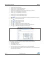
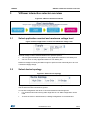
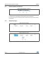
UM1874 User Manual TwisterSIM Introduction TwisterSIM is a unique Electro-Thermal simulator that helps shorten the design solution cycle by enabling, in a few clicks, complex engineering evaluations with accurate simulations like load-compatibility, wiring harness optimization, fault condition impact analysis, diagnostic behavior analysis and Dynamic Thermal performance. A built-in Interactive Selector provides a short list of suitable devices based on first level system requirements. It assists in detailing the specific system configuration with layout, load and driving profile customization to build an accurate model of the final application. Simulation results, including junction and case thermal profiles, load current and diagnostic behavior are shown on dedicated scopes views or exported in a number of different commonly used formats. TwisterSIM supports a large selection of Low/High-side driver/switches and H-bridges for Motor Control. A trial version, to explore the main functionalities of TwisterSIM, is available for download at www.st.com/twistersim and it also contains, in the main toolbar, the instructions to request an activation code (free of charge but subject to STMicroelectronics approval) for the full version. An on-line forum provides additional support to TwisterSIM users. Access to the forum is available at www.st.com/twistersim-forum. April 2015 DocID027637 Rev 3 1/43 www.st.com 1 Contents UM1874 Contents 1 Overview . . . . . . . . . . . . . . . . . . . . . . . . . . . . . . . . . . . . . . . . . . . . . . . . . . 6 2 Electro thermal simulator . . . . . . . . . . . . . . . . . . . . . . . . . . . . . . . . . . . . . 8 2.1 2.2 2.3 2.4 2.5 3 2/43 Device selection and parameters setting . . . . . . . . . . . . . . . . . . . . . . . . . . 8 2.1.1 General device parameters . . . . . . . . . . . . . . . . . . . . . . . . . . . . . . . . . . . 8 2.1.2 H-Bridge Device parameters . . . . . . . . . . . . . . . . . . . . . . . . . . . . . . . . . . 9 2.1.3 24V Device parameters . . . . . . . . . . . . . . . . . . . . . . . . . . . . . . . . . . . . . . 9 2.1.4 M07 Device parameters . . . . . . . . . . . . . . . . . . . . . . . . . . . . . . . . . . . . . . 9 2.1.5 Multichannel Options (2 or 4 channels devices) . . . . . . . . . . . . . . . . . . . 9 Source selection and setting . . . . . . . . . . . . . . . . . . . . . . . . . . . . . . . . . . 10 2.2.1 DC voltage setting . . . . . . . . . . . . . . . . . . . . . . . . . . . . . . . . . . . . . . . . . 10 2.2.2 Voltage profile setting . . . . . . . . . . . . . . . . . . . . . . . . . . . . . . . . . . . . . . 10 Line and sense resistances . . . . . . . . . . . . . . . . . . . . . . . . . . . . . . . . . . . 12 2.3.1 Line-in resistor . . . . . . . . . . . . . . . . . . . . . . . . . . . . . . . . . . . . . . . . . . . . 12 2.3.2 Line-out resistors . . . . . . . . . . . . . . . . . . . . . . . . . . . . . . . . . . . . . . . . . . 12 2.3.3 Sense resistors . . . . . . . . . . . . . . . . . . . . . . . . . . . . . . . . . . . . . . . . . . . 13 Control source . . . . . . . . . . . . . . . . . . . . . . . . . . . . . . . . . . . . . . . . . . . . . 14 2.4.1 Control source type . . . . . . . . . . . . . . . . . . . . . . . . . . . . . . . . . . . . . . . . 15 2.4.2 H-Bridge input setting . . . . . . . . . . . . . . . . . . . . . . . . . . . . . . . . . . . . . . 16 Load selection . . . . . . . . . . . . . . . . . . . . . . . . . . . . . . . . . . . . . . . . . . . . . 17 2.5.1 Resistor as load . . . . . . . . . . . . . . . . . . . . . . . . . . . . . . . . . . . . . . . . . . . 18 2.5.2 RC parallel as load . . . . . . . . . . . . . . . . . . . . . . . . . . . . . . . . . . . . . . . . 19 2.5.3 RL series as load . . . . . . . . . . . . . . . . . . . . . . . . . . . . . . . . . . . . . . . . . . 20 2.5.4 Current, RL and device power dissipation profile as load . . . . . . . . . . . 20 2.5.5 PMDC machine as load . . . . . . . . . . . . . . . . . . . . . . . . . . . . . . . . . . . . . 22 2.5.6 Lamp as load . . . . . . . . . . . . . . . . . . . . . . . . . . . . . . . . . . . . . . . . . . . . . 24 2.5.7 Thermal electrical simulation setup . . . . . . . . . . . . . . . . . . . . . . . . . . . . 25 2.5.8 Graphical simulation results . . . . . . . . . . . . . . . . . . . . . . . . . . . . . . . . . . 26 VIPower interactive selector overview . . . . . . . . . . . . . . . . . . . . . . . . . 29 3.1 Select application nominal and maximum voltage level . . . . . . . . . . . . . . 29 3.2 Select device topology . . . . . . . . . . . . . . . . . . . . . . . . . . . . . . . . . . . . . . . 29 3.3 Select number of channels . . . . . . . . . . . . . . . . . . . . . . . . . . . . . . . . . . . . 30 DocID027637 Rev 3 UM1874 Contents 3.4 Select load type . . . . . . . . . . . . . . . . . . . . . . . . . . . . . . . . . . . . . . . . . . . . 30 3.5 Source type setting . . . . . . . . . . . . . . . . . . . . . . . . . . . . . . . . . . . . . . . . . . 32 3.6 Set ambient & initial device temperature . . . . . . . . . . . . . . . . . . . . . . . . . 32 3.7 Select PCB type . . . . . . . . . . . . . . . . . . . . . . . . . . . . . . . . . . . . . . . . . . . . 33 3.8 Suggested devices . . . . . . . . . . . . . . . . . . . . . . . . . . . . . . . . . . . . . . . . . . 33 Appendix A Limited license agreement for ST materials evaluation. . . . . . . . . 35 Revision history . . . . . . . . . . . . . . . . . . . . . . . . . . . . . . . . . . . . . . . . . . . . . . . . . . . . 42 DocID027637 Rev 3 3/43 3 List of tables UM1874 List of tables Table 1. 4/43 Document revision history . . . . . . . . . . . . . . . . . . . . . . . . . . . . . . . . . . . . . . . . . . . . . . . . . 42 DocID027637 Rev 3 UM1874 List of figures List of figures Figure 1. Figure 2. Figure 3. Figure 4. Figure 5. Figure 6. Figure 7. Figure 8. Figure 9. Figure 10. Figure 11. Figure 12. Figure 13. Figure 14. Figure 15. Figure 16. Figure 17. Figure 18. Figure 19. Figure 20. Figure 21. Figure 22. Figure 23. Figure 24. Figure 25. Figure 26. Figure 27. Figure 28. Figure 29. Figure 30. Figure 31. Figure 32. Figure 33. Figure 34. Figure 35. Figure 36. Figure 37. Figure 38. TwisterSIM main view . . . . . . . . . . . . . . . . . . . . . . . . . . . . . . . . . . . . . . . . . . . . . . . . . . . . . . 6 Device selection and parameters setting . . . . . . . . . . . . . . . . . . . . . . . . . . . . . . . . . . . . . . . 8 DC voltage setting . . . . . . . . . . . . . . . . . . . . . . . . . . . . . . . . . . . . . . . . . . . . . . . . . . . . . . . 10 Voltage profile setting . . . . . . . . . . . . . . . . . . . . . . . . . . . . . . . . . . . . . . . . . . . . . . . . . . . . . 11 Line-in resistor . . . . . . . . . . . . . . . . . . . . . . . . . . . . . . . . . . . . . . . . . . . . . . . . . . . . . . . . . . 12 Line-out resistors . . . . . . . . . . . . . . . . . . . . . . . . . . . . . . . . . . . . . . . . . . . . . . . . . . . . . . . . 13 Sense resistors . . . . . . . . . . . . . . . . . . . . . . . . . . . . . . . . . . . . . . . . . . . . . . . . . . . . . . . . . . 14 Control source type. . . . . . . . . . . . . . . . . . . . . . . . . . . . . . . . . . . . . . . . . . . . . . . . . . . . . . . 15 PWM profile selection . . . . . . . . . . . . . . . . . . . . . . . . . . . . . . . . . . . . . . . . . . . . . . . . . . . . . 16 H-Bridge input setting . . . . . . . . . . . . . . . . . . . . . . . . . . . . . . . . . . . . . . . . . . . . . . . . . . . . . 17 Load selection. . . . . . . . . . . . . . . . . . . . . . . . . . . . . . . . . . . . . . . . . . . . . . . . . . . . . . . . . . . 18 Resistor as load . . . . . . . . . . . . . . . . . . . . . . . . . . . . . . . . . . . . . . . . . . . . . . . . . . . . . . . . . 19 RC parallel as load . . . . . . . . . . . . . . . . . . . . . . . . . . . . . . . . . . . . . . . . . . . . . . . . . . . . . . . 19 RL series as load . . . . . . . . . . . . . . . . . . . . . . . . . . . . . . . . . . . . . . . . . . . . . . . . . . . . . . . . 20 Current profile . . . . . . . . . . . . . . . . . . . . . . . . . . . . . . . . . . . . . . . . . . . . . . . . . . . . . . . . . . . 21 RL load profile. . . . . . . . . . . . . . . . . . . . . . . . . . . . . . . . . . . . . . . . . . . . . . . . . . . . . . . . . . . 21 Device power dissipation profile . . . . . . . . . . . . . . . . . . . . . . . . . . . . . . . . . . . . . . . . . . . . . 22 PMDC machine as load . . . . . . . . . . . . . . . . . . . . . . . . . . . . . . . . . . . . . . . . . . . . . . . . . . . 23 Lamp as load . . . . . . . . . . . . . . . . . . . . . . . . . . . . . . . . . . . . . . . . . . . . . . . . . . . . . . . . . . . 24 Lamp harness resistors . . . . . . . . . . . . . . . . . . . . . . . . . . . . . . . . . . . . . . . . . . . . . . . . . . . 25 Thermal electrical simulation setup . . . . . . . . . . . . . . . . . . . . . . . . . . . . . . . . . . . . . . . . . . 26 Simulation progress bar . . . . . . . . . . . . . . . . . . . . . . . . . . . . . . . . . . . . . . . . . . . . . . . . . . . 26 Graphical simulation results . . . . . . . . . . . . . . . . . . . . . . . . . . . . . . . . . . . . . . . . . . . . . . . . 27 Create a new function to plot . . . . . . . . . . . . . . . . . . . . . . . . . . . . . . . . . . . . . . . . . . . . . . . 28 VIPower interactive selector . . . . . . . . . . . . . . . . . . . . . . . . . . . . . . . . . . . . . . . . . . . . . . . . 29 Select application nominal and maximum voltage level . . . . . . . . . . . . . . . . . . . . . . . . . . . 29 Select device topology . . . . . . . . . . . . . . . . . . . . . . . . . . . . . . . . . . . . . . . . . . . . . . . . . . . . 29 Select number of channels . . . . . . . . . . . . . . . . . . . . . . . . . . . . . . . . . . . . . . . . . . . . . . . . . 30 Select load type . . . . . . . . . . . . . . . . . . . . . . . . . . . . . . . . . . . . . . . . . . . . . . . . . . . . . . . . . 30 Resistor as load . . . . . . . . . . . . . . . . . . . . . . . . . . . . . . . . . . . . . . . . . . . . . . . . . . . . . . . . . 30 Inductor as load . . . . . . . . . . . . . . . . . . . . . . . . . . . . . . . . . . . . . . . . . . . . . . . . . . . . . . . . . 31 Lamp (by current) as load . . . . . . . . . . . . . . . . . . . . . . . . . . . . . . . . . . . . . . . . . . . . . . . . . . 31 Lamp (by Power) as load . . . . . . . . . . . . . . . . . . . . . . . . . . . . . . . . . . . . . . . . . . . . . . . . . . 31 PMDC motor as load . . . . . . . . . . . . . . . . . . . . . . . . . . . . . . . . . . . . . . . . . . . . . . . . . . . . . 31 Source type setting . . . . . . . . . . . . . . . . . . . . . . . . . . . . . . . . . . . . . . . . . . . . . . . . . . . . . . . 32 Set ambient & initial device temperature . . . . . . . . . . . . . . . . . . . . . . . . . . . . . . . . . . . . . . 32 Select PCB type . . . . . . . . . . . . . . . . . . . . . . . . . . . . . . . . . . . . . . . . . . . . . . . . . . . . . . . . . 33 Suggested devices . . . . . . . . . . . . . . . . . . . . . . . . . . . . . . . . . . . . . . . . . . . . . . . . . . . . . . . 33 DocID027637 Rev 3 5/43 5 Overview 1 UM1874 Overview Main start window (Figure 1) functionalities: 1. System Layout: it shows a typical control schematic, including a specific device (selectable from a list), supply voltage, line harnesses, common loads and a configurable control input to fit the simulation conditions to a specific architecture 2. Project Specifications: on the left side, the main project information is summarized 3. Simulation pane: on bottom-right part, it allows to customize simulation parameters and open a plot window 4. VIPower Interactive Selector: built-in "Get Started" utility to facilitate device identification based on first level system requirements 5. Quick View: on the bottom side the main electrical data and package info of the device are outlined. The link View Datasheet allows downloading the datasheet. Figure 1. TwisterSIM main view On menu items or toolbar: 6/43 Click "File" and select "Load System Layout & Data" or click button, to load a complete system layout and simulation data, previously saved Click "File" and select "Save System Layout & Data" or click complete system layout and simulation data Click "Tools" and select "VIPower Interactive Selector" or click "Get Started" button, to start VIPower Interactive Selector tool Click “Help” to view this guide, to read the disclaimer or go to the forum page. DocID027637 Rev 3 button, to save a UM1874 Overview On system layout: Click on the components icons to configure and change their values. On simulation pane: Configure simulation parameters (Section 2.5.7: Thermal electrical simulation setup) then click "Simulate" button to start simulation. A progress bar indicates the state of the simulation. A plotting window automatically opens when the simulation ends. DocID027637 Rev 3 7/43 7 Electro thermal simulator UM1874 2 Electro thermal simulator 2.1 Device selection and parameters setting Click on the Device Icon in the main window, a new frame opens (Figure 2) where a specific device can be selected and the related parameters set. Figure 2. Device selection and parameters setting 2.1.1 General device parameters Typical values are preselected for each device. All parameters with a white background may be changed. Change them manually by inserting a specific value or clicking up/down in the numeric boxes. 8/43 DocID027637 Rev 3 UM1874 Electro thermal simulator The range of values allowed depends on the specific device selected: Ambient and Junction temperature at the beginning of the simulation. Accepted values are between -40°C and 150°C for all devices ILimH @25°C (A): Output Current Limitation (for Tj < Ttsd) ILimL @25°C (A): Output Current Limitation during thermal cycling (for Tj > Ttsd) RdsOn @25°C (mΩ): Output drain-source on state resistance Thermal Shutdown Temperature (Ttsd,°C). Accepted values are between 150°C and 200°C for all devices Turn-off output voltage clamp (Vdemag) Cx (°C/W) and Rx (W · S/°C): Thermal Fitting model parameters (see component datasheet for further information). In PCB pop-up Menu choose from a list of preset Heat Sink (with preset values of Cx and Rx, accordingly to the relevant datasheet) or set "Custom PCB" to manually insert Cx and Rx values. Values outside the boundaries are automatically restored to the max/min allowed value. 2.1.2 H-Bridge Device parameters ILimH (A): High-Side Current Limitation ISD_LS (A): Low-Side Shutdown Current Ron HS/LS @25°C (Ω): high/low side drain-source on state resistances. H-Bridge Device selection is not available if Power Profile is selected. H-Bridge Device selection disables Power Profile, Lamp Selection and Reverse Diode selection in parallel with RL load. 2.1.3 24V Device parameters 2.1.4 2.1.5 V(FR_Stby) = 5: Check to connect Fault reset standby pin @ 5V. M07 Device parameters V(FAULTRST) = 5: Check to connect Fault reset pin @ 5V V(sel0) = 5: Check to connect sel0 pin @ 5V V(sel1) = 5: Check to connect sel1 pin @ 5V. Multichannel Options (2 or 4 channels devices) Check "connect In channels in parallel" to connect the Inputs of the channels in parallel. Relevant changes are reflected in the "source section" Check "connect Out channels in parallel" to connect the Outputs of the channels in parallel. Relevant changes are reflected in the "load section" Click OK to accept changes Click Cancel to restore previous device and parameters Click Help to read the help file on this topic. Selected Device name and PCB thermal parameters are reported in the main window. Refer to the relevant datasheet for Device specific parameter ranges. DocID027637 Rev 3 9/43 11 Electro thermal simulator 2.2 UM1874 Source selection and setting Click on the Battery symbol (Vbatt) in the main window, a new frame opens (Figure 3) where the battery voltage can be modified. Select "DC" or "Profile" to set the Source voltage. 2.2.1 DC voltage setting Figure 3. DC voltage setting Change the value manually by inserting it in the numeric box. Values outside the boundaries are automatically restored to the max/min allowed value. 2.2.2 Voltage profile setting Click Profile, a new frame opens (Figure 4) allowing to insert a custom profile by specifying time-values pairs in the corresponding fields or load values from a .txt/.csv file ( time values in the 1st column and Voltage values in the 2nd, max 150 rows). 10/43 DocID027637 Rev 3 UM1874 Electro thermal simulator Figure 4. Voltage profile setting Define the output after the final value by: Cyclic repetition (Voltage values sequence is repeated continuously during the simulation) Holding final value (Last voltage value is maintained throughout the simulation). Time values must be inserted as a increasing monotonic sequence (i.e., Tn+1>Tn). Click to clear table Click to load values from file Click OK to accept changes Click Cancel to restore previous values Click Help to read the help file on this topic DocID027637 Rev 3 11/43 11 Electro thermal simulator 2.3 UM1874 Line and sense resistances Click on the Resistors symbols in the main window to change Line-in, Line-out and Sense resistances for analog devices only. 2.3.1 Line-in resistor Change the value manually by inserting it in the numeric box (Figure 5). Figure 5. Line-in resistor Values outside the boundaries are automatically restored to the maximum allowed value. Accepted values are between 5mΩ and 1Ω. 2.3.2 Line-out resistors Change the values manually by inserting them in the numeric boxes (Figure 6). 12/43 DocID027637 Rev 3 UM1874 Electro thermal simulator Figure 6. Line-out resistors Values outside the boundaries are automatically restored to the max/min allowed value. Accepted values are between 10mΩ and 1kΩ. The number of enabled Line-in resistors is equal to the number of output channels for the selected device. 2.3.3 Sense resistors Only for analog current sense devices, Sense resistors values can be set to simulate current sense diagnostic voltage conversion (Figure 7). Change the values manually by inserting them in the numeric boxes. DocID027637 Rev 3 13/43 28 Electro thermal simulator UM1874 Figure 7. Sense resistors Values outside the boundaries are automatically restored to the max/min allowed value. Accepted values are between 100Ω and 10kΩ. The number of enabled sense resistors is equal to the number of output channels for the selected device. Click OK to accept changes Click Cancel to restore previous values Click Help to read the help file on this topic Resistance values are reported in the main window. 2.4 Control source Click on the Control Voltage symbol (Vin) in the main window, a new frame opens where the control type for each channel can be selected (Figure 8). The number of visible Tabs is equal to the number of output channels of the selected device. 14/43 DocID027637 Rev 3 UM1874 2.4.1 Electro thermal simulator Control source type Figure 8. Control source type Selecting "DC" Source type a 5V DC source voltage is applied to the "In" pin, starting from "Start Time". Selecting "PWM" Source type a 5V square wave source voltage is applied to the "In" pin, with a specific "Frequency" and "Duty Cycle", starting from "Start Time". Selecting “PWM” profile Source type a new frame opens (Figure 9) in order to insert a custom profile by specifying time, frequency and duty cycle in the corresponding fields or load values from a .txt/.csv file (time values in the 1st column, frequency in the 2nd and duty cycle values in the 3rd, max 150 rows). Change the values manually by inserting them in the numeric boxes. Values outside the boundaries are automatically restored to the max/min allowed value. DocID027637 Rev 3 15/43 28 Electro thermal simulator UM1874 Figure 9. PWM profile selection Define the output after the final value by: Cyclic repetition (Frequency and duty cycle values sequence is repeated continuously during the simulation) Holding final value (Last frequency and duty cycle values are maintained throughout the simulation) Time values must be inserted as a increasing monotonic sequence (i.e., Tn+1>Tn). Click to clear table Click to load values from file PWM and PWM Profile for the selected channel are not available if Current or Power Profile is selected. PWM and PWM Profile disable the Current and Power Profile selection for the selected channel. 2.4.2 H-Bridge input setting Click on the "PWM, Vin A,B” in the main window then select “Input A,B” and a new frame (Figure 10) allows inserting a custom profile by specifying time, Input A and Input B in the corresponding fields or load values from a .txt/.csv file (time values in the 1st column, Input A in the 2nd and Input B values in the 3rd, max 150 rows). Define the output after the final value by selecting: 16/43 Cyclic repetition (Input A and Input B values sequence is repeated during the simulation) Holding final value (Last Input A and Input B values are maintained throughout the simulation) DocID027637 Rev 3 UM1874 Electro thermal simulator Figure 10. H-Bridge input setting Time values must be inserted as a increasing monotonic sequence (i.e., Tn+1>Tn). Input A and Input B are logical values: Set Input A = 1 and Input B = 0 to activate HS1-LS2 diagonal Set Input A = 0 and Input B = 1 to activate HS2-LS1 diagonal Click to reset table Click to load values from file Changes in Input selection disable Current Profile selection Reset table to enable Current Profile selection with DC source type. 2.5 Click OK to accept changes Click Cancel to restore previous values Click Help to read the help file on this topic Load selection Click on the Load icon in the main window, a new frame opens (Figure 11) where load parameters for each output channel can be selected. Number of visible Tabs is equal to the number of output channels for the selected device. DocID027637 Rev 3 17/43 28 Electro thermal simulator UM1874 Figure 11. Load selection Select one of the following loads: Resistor (Figure 12) RC (Figure 13) RL (Figure 14) Current, RL or Power Profile (Figure 15) PMDC Machine (Figure 18) From the counter "Number of Lamps" a maximum of 10 lamps per channel can be selected. If "Select channels Separately" is unchecked, the same load is selected for each channel. The values of each component in the load can be manipulated. Click on the components icons to change the values. If no load is selected, an open circuit symbol appears. 2.5.1 Click OK to accept changes Click Cancel to restore previous layout Click Help to read the help file on this topic Resistor as load Click "Resistor" button to select a Resistive load and then click on the Resistor symbol in the Layout to change its value. 18/43 DocID027637 Rev 3 UM1874 Electro thermal simulator Figure 12. Resistor as load Change the values manually by inserting them in the numeric boxes. Values outside the boundaries are automatically restored to the max/min value allowed. Accepted values are between 10mΩ and 10MΩ for resistance. 2.5.2 "Turn On" time: connect Resistor during simulation at a specific time "Turn Off" time: disconnect Resistor during simulation at a specific time Click OK to accept changes Click Cancel to restore previous values Click Help to read the help file on this topic RC parallel as load Click "RC Load" button to select an RC parallel load and then click on the Capacitor symbol in the layout to change its value Figure 13. RC parallel as load DocID027637 Rev 3 19/43 28 Electro thermal simulator UM1874 Change the values manually by inserting them in the numeric boxes. Values outside the boundaries are automatically restored to the max/min allowed value. Accepted values are between 10mΩ and 10MΩ for resistance and between 1nF and 1F for Capacitance. 2.5.3 Click OK to accept changes Click Cancel to restore previous values Click Help to read the help file on this topic RL series as load Click "RL Load" button to select an RL series load and then click on the Inductor symbol in the layout to change its value Figure 14. RL series as load Change the values manually by inserting them in the numeric boxes. Values outside the boundaries are automatically restored to the max/min value allowed. Accepted values are between 10mΩ and 10MΩ for resistance and between 0.5μH and 1H for Inductance. Check "Reverse Diode" to select a reverse diode in parallel with RL load. Accepted values are between 10mV and 1V for "Forward voltage" and between 1mΩ and 1Ω for "Ron". Reverse Diode is not available for H-Bridge Devices. Click OK to accept changes Click Cancel to restore previous values Click Help to read the help file on this topic RL Load disables Lamp selection for selected channel. 2.5.4 Current, RL and device power dissipation profile as load Channel 1: 20/43 Click "I/RL/W Profile" button to select a Current, RL Load or Power Loss Profile and then click on the corresponding I/RL/W symbol in the layout to change its value. DocID027637 Rev 3 UM1874 Electro thermal simulator Channels 2...4: Click "I/RL Profile" button to select a Current or RL Load Profile and then click on the corresponding I/RL symbol in the layout to change its value. Select Current (Figure 15), RL Load (Figure 16) or Power Loss Profile (1st channel) (Figure 17) from the pop-up menu. Figure 15. Current profile Figure 16. RL load profile DocID027637 Rev 3 21/43 28 Electro thermal simulator UM1874 Figure 17. Device power dissipation profile Insert a custom profile by specifying time-value pairs or triples in the corresponding fields or load values from a .txt/.csv file (time values in the 1st column; Current, Resistance or Power values in the 2nd; Inductance values in the 3rd (Only for RL Load profile), max 150 rows). For Resistance Profile insert 0 in the Inductance fields. Define the output after the final value by: Cyclic repetition (Current, RL Load or Power values sequence is repeated continuously during the simulation) Holding final value (Last Current, RL Load or Power value is maintained throughout the simulation). Time values must be inserted as a increasing monotonic sequence (i.e., Tn+1>Tn). Click to clear table. Click to load values from file Establishing a Current Profile, disables PWM selection for the selected channel, Input AB for H-Bridge devices (use negative currents to invert H-Bridge polarity). Establishing a Power Profile (1st channel) disables PWM, channels and H-Bridge selection. Click OK to accept changes Click Cancel to restore previous values Click Help to read the help file on this topic A current (Figure 15), RL Load (Figure 16) or Power (Figure 17) symbol appears in the load layout. I/RL/W Profile disables Lamp selection for selected channel. 2.5.5 PMDC machine as load Click "PMDC Machine" button to select a Permanent Magnet DC Machine and then click on the PMDC symbol in the Layout to change its parameters. Change the values manually by inserting them in the numeric boxes. Values outside the boundaries are automatically restored to the max/min value allowed. 22/43 DocID027637 Rev 3 UM1874 Electro thermal simulator Figure 18. PMDC machine as load PMDC Machine parameters: Armature Resistance(Ω): The resistance of the winding Armature Inductance (H): The inductance of the winding Torque constant (N·m/A): The torque per current constant Total inertia (kg·m2): The total inertia momentum of the motor and the load Viscous friction coefficient (N·m·s): The total friction coefficient Coulomb friction torque (N·m): The total friction torque constant Initial speed (rad/s): The initial rotation speed Check parallel conductance to insert a capacitance in parallel to PMDC machine. PMDC Specifical signals: TL (N·m): The electromechanical torque load at the input of the DC machine Te (N·m): The electromechanical torque developed by the DC machine ω (rad/s): The rotational speed of the DC machine DocID027637 Rev 3 23/43 28 Electro thermal simulator UM1874 Mechanical input (Torque Load): Hold Motor: Hold motor position (TL=Te and ω=0) Open Load: No electromechanical torque load at the input (TL=0) Torque Profile: Insert a custom profile by specifying time-values pairs in the corresponding fields or load values from a .txt/.csv file (time values in the 1st column and torque values in the 2nd, max 150 rows). Define the output after the final value by: Cyclic repetition (Torque values sequence is repeated continuously during the simulation) Holding final value (Last Torque value is maintained throughout the simulation). Time values must be inserted as a increasing monotonic sequence (i.e., Tn+1>Tn). Click to reset table Click to load values from file Click OK to accept changes Click Cancel to restore previous values Click Help to read the help file on this topic PMDC Machine disables Lamp selection for selected channel. 2.5.6 Lamp as load Select up to 10 lamps from the "Number of Lamps" counter and then click on a Lamp icon in the layout to change the values. Figure 19. Lamp as load Lamps can be placed alone or in parallel to a resistor or a capacitor and they can have different values. Select a lamp from the drop down menu, according to its voltage and power requirements. 24/43 DocID027637 Rev 3 UM1874 Electro thermal simulator Lamp parameters: "12V": select 12V lamps "24V": select 24V lamps "Turn On" time: connect lamp during simulation at a specific time "Turn Off" time: disconnect lamp during simulation at a specific time "Bulbs Temperature": Initial filament temperature (°C). Accepted values are between 40°C and 1000°C. This value is common to all lamps inserted Click OK to accept changes Click Cancel to restore previous values Click Help to read the help file on this topic Lamp harness resistors Click on the Resistors symbols in the layout to set a wiring harness lamp resistance for each lamp Figure 20. Lamp harness resistors Change the value manually by inserting it in the numeric box. Values outside the boundaries are automatically restored to the max/min allowed value. Accepted values are between 1mΩ and 10Ω. 2.5.7 Click OK to accept changes Click Cancel to restore previous values Click Help to read the help file on this topic Thermal electrical simulation setup Check the box "Stop simulation when Tjx>" to interrupt the simulation when Tjx is higher than the value specified in the box Choose simulation time and then Click "Simulate" button to Start. DocID027637 Rev 3 25/43 28 Electro thermal simulator UM1874 Figure 21. Thermal electrical simulation setup "Step Size" is automatically selected based on the Device/Load configuration. Changing Step Size affects the simulation speed and accuracy: For best precision set a lower Step Size. For faster simulation set a higher Step Size. A higher Step Size may cause convergence problems. "Write data every" is automatically selected based on "Simulation Time" and "Step Size", in order to optimize resolution and memory requirements. Lower values do not affect simulation accuracy but may cause memory problems. A progress bar indicates the state of the simulation. Figure 22. Simulation progress bar Computation time is principally a function of the kind of load (inductive loads take a longer time), "Simulation Time" and "Step Size" parameters. At the end of simulation a plot window shows simulation results. 2.5.8 Click "Stop" button to stop simulation Click "Plot" button to show or reopen Plot window Click "Plot" button during simulation to show partial results: A notice in the plot informs about the state of simulation. Graphical simulation results When the simulation is over, a new window is opened to show the simulation results. 26/43 DocID027637 Rev 3 UM1874 Electro thermal simulator Figure 23. Graphical simulation results Left click on the signals list checkbox to add or remove them in the plot (Figure 23) Right click on the signals to change color, line style or signal name Right click on the plot to change titles, un-zoom, un-pan, copy save or print the image Change the Subplots number to show simulation results in up to 4 subplots. DocID027637 Rev 3 27/43 28 Electro thermal simulator UM1874 Check "Grid" to show grid lines Check "Zoom X" to enable Horizontal zoom Check "Zoom Y" to enable Vertical zoom Check "Pan" to interactively move the plot view, left clicking on the plot Check "Log X" to set logarithmic X axes scale Check "Log Y" to set logarithmic Y axes scale Check "SyncX" to synchronize Subplots X axes Check "SyncY" to synchronize Subplots Y axes Click text file to save the results to a data file for exporting to spreadsheets or a generic Click to save a picture of the plot Click to copy a picture of the plot Click to print a picture of the plot Click to show this help Click to restore the scale ranges to default values Click to restore the scale ranges to the values before last zoom Click to add signals combination or function to plot: Figure 24. Create a new function to plot Insert a signal combination or function, clicking or typing in the function field. 28/43 Click OK to insert function Click Clear to clear text Click Cancel to return to plot Click "Plot" button in the main window to show or reopen Plot window Click "Plot" button during simulation to show partial results: a notice in the plot informs about the state of simulation DocID027637 Rev 3 UM1874 3 VIPower interactive selector overview VIPower interactive selector overview Figure 25. VIPower interactive selector 3.1 Select application nominal and maximum voltage level Figure 26. Select application nominal and maximum voltage level Nominal voltage could be selected between two possible options: 12V: for typical Automotive systems or every application based on 12V battery line 24V: for Truck or every application based on 24V battery line Maximum voltage is used by simulation engine to perform worst-case analysis or to set a customized Supply Range. 3.2 Select device topology Figure 27. Select device topology In High Side configuration the driver is connected between voltage line and load; the load has the other terminal connected to ground. In Low Side configuration the driver is connected between load and ground. For unidirectional motors driving either High Side or Low Side configuration can be used To drive the motor in both directions, H-Bridge configuration is recommended. DocID027637 Rev 3 29/43 34 VIPower interactive selector overview 3.3 UM1874 Select number of channels Figure 28. Select number of channels High Side Switches are available in Single, Dual and Quad channel configurations. Low Side Switches are available in Single and Dual channel configurations. For multi-channel option it is assumed that each channel drives the same selected load at the same time. 3.4 Select load type Figure 29. Select load type Figure 30. Resistor as load 30/43 DocID027637 Rev 3 UM1874 VIPower interactive selector overview Figure 31. Inductor as load Figure 32. Lamp (by current) as load Figure 33. Lamp (by Power) as load Figure 34. PMDC motor as load DocID027637 Rev 3 31/43 34 VIPower interactive selector overview 3.5 UM1874 Resistor: Select this option and input the load resistance (Figure 30) Inductor: Select this option and input the coil inductance and resistance as well as the coil current when the driver output is switched off (Figure 31) Lamp: Select this option and input the bulb power or the lamp in rush current and the steady state bulb current (Figure 32 and Figure 33) Motor: Select this option and input the motor stall current and the steady state motor current (Figure 34) The same load is available for each channel. Source type setting Figure 35. Source type setting Select if the load is driven in DC or in PWM. In case of PWM selection input frequency and duty cycle. 3.6 DC: If the application requires activating the load in a continuous mode for indefinite time PWM: If the application specification requires to drive the load to a specific frequency and duty cycle. Set ambient & initial device temperature Figure 36. Set ambient & initial device temperature Environment temperature, under worst-case conditions, is mandatory for selecting the devices with the best thermal fitting. For standard Automotive applications 85°C is typically used, while it is usually 105°C for Automotive under-hood. 32/43 DocID027637 Rev 3 UM1874 3.7 VIPower interactive selector overview Select PCB type Figure 37. Select PCB type Select the PCB type in line with the specific application: FootPrint · 2 Layers - 2cm2 · 2 Layers - 8cm2 · 4 Layers 3.8 Suggested devices Figure 38. Suggested devices DocID027637 Rev 3 33/43 34 VIPower interactive selector overview UM1874 Select one of suggested devices or go back to points 1-7 and change application layout. 34/43 Click Export Layout for Simulation to verify selected layout in TwisterSIM for available devices Click Reset to restart VIPower Interactive Selection Click Help to read the help file on this topic. DocID027637 Rev 3 UM1874 Limited license agreement for ST materials evaluation Appendix A Limited license agreement for ST materials evaluation IMPORTANT-READ CAREFULLY: This Limited License Agreement (“LLA) for ST materials is made between you on behalf of yourself, and on behalf of any entity by which you are employed or engaged (collectively referred to in this LLA as "You" or “Licensee”) and STMicroelectronics International NV, a company incorporated under the laws of the Netherlands acting for the purpose of this LLA through its Swiss branch located at 39, Chemin du Champ des Filles, 1228 Plan-les-Ouates, Geneva, Switzerland (hereinafter “ST”). Affiliates shall mean any corporation, partnership, or other entity that, directly or indirectly, owns, is owned by, or is under common ownership with ST, for so long as such ownership exists. For the purposes of the foregoing, "own", "owned," or "ownership" shall mean ownership of more than fifty percent (50%) of the stock or other equity interests entitled to vote for the election of directors or an equivalent governing body. The ST materials licensed under this LLA shall mean the software and/or any hardware material which accompany or are otherwise made available by ST and/or its Affiliates upon agreeing to this LLA, including any associated media, Documentation (collectively the “Licensed Materials”). Documentation shall include any comments, annotations, instructions, manuals, and other materials, whether in printed or electronic form, including without limitation installation manuals, user’s guides, and programmer guides, related to any software and/or any hardware material made available under this LLA. The Licensed Materials include any software updates, hardware products and supplements that ST and/or its Affiliates may provide You or make available to You after the date You obtain the Licensed Materials to the extent that such items are not accompanied by a separate license agreement or other terms of use. THE LICENSED MATERIALS ARE LICENSED TO YOU ON THE CONDITION THAT YOU ACCEPT ALL THE TERMS AND CONDITIONS OF THIS LLA. BY CLICKING ON THE "I ACCEPT" BUTTON OR BY INSTALLING, COPYING, DOWNLOADING, ACCESSING OR OTHERWISE USING THE LICENSED MATERIALS, YOU AGREE TO BE BOUND BY THE TERMS OF THIS LLA. IF YOU DO NOT AGREE WITH ANY CONDITION OF THIS LLA, DO NOT INSTALL, ACCESS OR USE THE LICENSED MATERIALS. 1. LIMITED LICENSE Subject to the terms and conditions of this LLA and applicable Open Source Terms (as defined hereafter) and during the term of this LLA, ST hereby grants You under intellectual property rights owned by ST and its Affiliates or under which ST and its Affiliates has the right to grant a license, a worldwide, non-exclusive, non-transferable, royalty-free, license, without the right to sub-license, to use internally the Licensed Materials solely and exclusively with ST chipsets or ST integrated circuits (collectively “ST Chipsets”) for the sole purpose of performing evaluation, simulation, testing and development of software/hardware applications and performing non-commercial demonstration of such Licensee’s software/hardware applications with ST Chipsets (“Limited License Purpose”). DocID027637 Rev 3 35/43 41 Limited license agreement for ST materials evaluation UM1874 To the extent the Licensed Materials are made available to You in source code and subject to the terms and conditions of this LLA, ST hereby grants You under intellectual property rights owned by ST and its Affiliates or under which ST and its Affiliates has the right to grant a license, during the term of this LLA, a worldwide, non-exclusive, royalty-free, nontransferable license, without the right to sublicense, to use, reproduce and modify the source code form of the Licensed Materials and compile such modified source code into new object code, for the Limited License Purpose only. Subject to the terms and conditions of this LLA, ST hereby grants You under intellectual property rights owned by ST and its Affiliates or under which ST and its Affiliates has the right to grant a license, a worldwide, non-exclusive, non-transferable, royalty-free, license without the right to sub-license, to use internally and make a reasonable number of copies of the Documentation provided by ST under this LLA, solely to support the Limited License Purpose. Subject to all limitations described herein, You are authorized to have third party contractors exercise for You and on your behalf the license rights as set forth above. You are fully responsible vis-à-vis ST for any act or omission of your contractors and any breach by Your contractors shall be deemed a breach by You hereunder. You acknowledge that the Licensed Materials have not been specifically designed to meet your individual requirements and that You have all information necessary to evaluate whether the Licensed Materials meet your requirements or not, and will be suitable for your intended use or application. Therefore the Licensed Materials shall be deemed accepted upon delivery to Licensee. You shall use, at your own risk, the Licensed Materials and any development that is obtained from such use. You acknowledge that ST and its Affiliates cannot in any way be held responsible for the consequences resulting from use of the Licensed Materials and any development made following such use of the Licensed Materials. You acknowledge you are receiving the Licensed Materials under a limited license and not as a purchaser of the Licensed Materials. 2. RESTRICTIONS Unless otherwise expressly stipulated under Article 1, You shall not, and shall not permit any third party to: (i) copy, reproduce or duplicate the Licensed Materials; (ii) translate, modify, adapt, decompile, disassemble or reverse engineer and make derivative works of (any portion of) the Licensed Materials; (iii) rent, disclose, publish, sell, assign, lease, lend, sublicense, market, transfer, distribute or otherwise provide third parties access to (any portion of) the Licensed Materials for any purpose; (iv) attempt to derive the source code, algorithmic nature or structure of any object code portions of the Licensed Materials; (v) use the Licensed Materials to create any product that competes with the Licensed Materials or ST Chipsets; (vi) remove or circumvent any protection or other restrictive technology mechanism of the Licensed Materials or ST Chipsets; (vii) disclose the results of the Licensed Materials’ performance to any third party; or (viii) otherwise use any portion of the Licensed Materials in any manner not expressly authorized by this LLA. 36/43 DocID027637 Rev 3 UM1874 Limited license agreement for ST materials evaluation Other than the limited expressed license granted to You under Article 1 herein, no other rights or licenses are granted, or implied by estoppel or otherwise, under any intellectual property rights of ST and/or its Affiliates or any intellectual property of a third-party residing in the Licensed Materials or in any other confidential information furnished by ST and its Affiliates, including (i) for the combination of such Licensed Materials or other confidential information with one or more other items (including items acquired from ST and/or its Affiliates) even if such items have no substantial use other than as part of such combination (ii) with respect to any trademark, trade or brand name, domain name, corporate name of ST and/or Affiliates, or any other name or mark, or contraction abbreviation or simulation thereof, (iii) under any intellectual property rights covering any standard set by a standard setting body and any de facto standards. You may not use the Licensed Materials for commercial purposes nor sell, or otherwise transfer it for value. Commercial purposes include the use of the Licensed Materials as a standalone product or in a product, to be distributed, marketed or otherwise offered for sale or for rent ultimately. For avoidance of doubt, nothing shall prevent the Licensee from distributing any of Licensee’s software/hardware applications, provided that such Licensee’s software/hardware applications do not contain any Licensed Material or part thereof and/or result in whole or in part from use of the Licensed Materials hereunder. You shall limit access and use of the Licensed Materials to You and those individuals who may be employed by You who have a need to access the Licensed Materials for the Limited License Purpose and provided that You shall ensure that such individuals shall comply with the provisions of this LLA, and except as expressly permitted under Article 1 or as otherwise expressly agreed in writing by ST, You shall not allow any third-party to use the Licensed Materials. You shall be liable towards ST for any damages due to a failure by such thirdparty(ies) to comply with the provisions of this LLA. ST and its Affiliates have no obligation to provide You with maintenance, technical support or updates for the Licensed Materials. 3. OWNERSHIP, COPYRIGHTS AND TRADEMARKS The Licensed Materials are and will remain the exclusive property of ST and/or its Affiliates or its licensors, whether or not specifically recognized or perfected under the laws of the country where the Licensed Materials are used. You will not take any action that jeopardizes ST and its Affiliates or its licensors' proprietary rights or acquire any rights in the Licensed Materials, except the limited rights specified in Article 1. All right, title and interest in and to the Licensed Materials, are owned or licensed by ST or its Affiliates or licensors. You shall ensure that all notices, including but not limited to all copyright and trademark notices of ST or its Affiliates or licensors are reproduced in any copy of the whole or any part of the Licensed Materials. You shall not remove, modify or alter any ST or its Affiliates’ or licensors’ copyright or trademark notice from any part of the Licensed Materials. DocID027637 Rev 3 37/43 41 Limited license agreement for ST materials evaluation 4. UM1874 CONFIDENTIALITY Confidential information shall include all information provided with the Licensed Materials which (a) is designated as “confidential”, “proprietary” or with a similar legend, (b) is by its own nature of a type which would reasonably be considered confidential and/or (c) is source code (“Confidential Information”). You may only use the Confidential Information for the Limited License Purpose and shall protect the confidentiality of the Confidential Information provided by ST and its Affiliates under this LLA by using the same degree of care, but not less than a reasonable degree of care, to prevent its unauthorized use, dissemination, or publication as You use to protect your own confidential information of like nature. You shall be liable towards ST for any damages incurred due to a failure by any employee having access to the Licensed Materials and/or the Confidential Information to comply with the provisions in this LLA. You shall immediately notify ST of any unauthorised use or disclosure of, or of any unauthorised access to, or of any theft or loss of the Licensed Materials or Confidential Information or part thereof, which comes to your notice. The confidentiality obligations shall not apply to Confidential Information, which can be shown by documentary evidence: (i) entered the public domain through no fault of the Licensee; or, (ii) was known to the Licensee prior to receipt from ST and its Affiliates; or, (iii) was disclosed to the Licensee by a third party having the right to disclose; or, (iv) was independently developed by the Licensee without use of the Licensed Materials or Confidential Information, the onus of proof of independence being on the Licensee. These confidentiality obligations shall survive any termination or expiration of the LLA for whatever cause. 5. DISCLAIMER OF WARRANTY YOU ACKNOWLEDGE THAT THE LICENSED MATERIALS AND ANY AND ALL PARTS THEREOF ARE PROVIDED “AS IS”. ST AND ITS AFFILIATES MAKE NO REPRESENTATIONS OR WARRANTIES WITH RESPECT TO THE LICENSED MATERIALS AND OR PARTS THEREOF WHETHER EXPRESS, IMPLIED, OR STATUTORY, INCLUDING BUT NOT LIMITED TO, IMPLIED WARRANTIES OF MERCHANTABILITY AND FITNESS FOR A PARTICULAR PURPOSE. SPECIFICALLY, WITHOUT LIMITING THE GENERALITY OF THE FOREGOING, ST AND ITS AFFILIATES MAKE NO REPRESENTATION OR WARRANTY THAT (I) THE USE OF THE LICENSED MATERIALS AND OR PARTS THEREOF WILL BE UNINTERRUPTED OR ERROR FREE, AND OR (II) ANY USE OF THE LICENSED MATERIALS AND OR PARTS THEREOF, WHETHER INTEGRATED INTO OTHER EQUIPMENT OR NOT, ARE FREE FROM INFRINGEMENT OF ANY THIRD PARTY INTELLECTUAL PROPERTY RIGHTS. IT SHALL BE YOUR SOLE RESPONSIBILITY TO MAKE SUCH DETERMINATION AS IS NECESSARY WITH RESPECT TO THE ACQUISITION OF LICENSES UNDER PATENTS AND OTHER INTELLECTUAL PROPERTY RIGHTS OF THIRD PARTIES. CONSEQUENTLY, ST AND ITS AFFILIATES DISCLAIM ANY LIABILITY IN CASE ANY SUCH USE INFRINGES ANY THIRD PARTY’S INTELLECTUAL PROPERTY RIGHTS. FURTHERMORE ST AND ITS AFFILIATES HEREBY DISCLAIM ANY WARRANTY AND LIABILITY WHATSOEVER FOR ANY DEVELOPMENT CREATED BY OR FOR YOU OR YOUR CUSTOMERS. 38/43 DocID027637 Rev 3 UM1874 Limited license agreement for ST materials evaluation YOU ACKNOWLEDGE THAT YOU HAVE RELIED ON NO WARRANTIES OTHER THAN THE EXPRESS WARRANTIES IN THIS LLA AND THAT NO WARRANTIES ARE MADE BY ST OR ITS AFFILIATES OR GRANTED BY LAW WHENEVER IT IS PERMITTED BY LAW. 6. OPEN SOURCE Some portion of the Licensed Materials might contain Open Source Software subject to Open Source Terms (as defined below) applicable for each such portion, as further specified in the Licensed Materials. Such Open Source Software is supplied to You under the applicable Open Source Terms and is not subject to the terms of this LLA to the extent the terms of this LLA are in conflict with such applicable Open Source Terms. Except for Open Source Software, You have no rights under this LLA to, and may not under any circumstances use the Licensed Materials or any parts thereof such that they become subject to any Open Source Terms. These actions include but are not limited to combining the Licensed Materials by means of incorporation or linking or otherwise. For the purpose of this LLA, “Open Source Terms” shall mean any open source license which requires as part of distribution of software that the source code of such software is distributed therewith, or any other open source license that complies with the Open Source Definition specified at www.opensource.org and any other comparable open source license such as for example GNU General Public License (GPL), Eclipse Public License (EPL), Apache Software License, BSD license and MIT license. “Open Source Software” shall mean any software that is licensed or distributed under Open Source Terms as specified in the Licensed Materials. 7. COMPLIANCE You agree not to use the Licensed Materials in violation of any law, statute, ordinance or other regulation or any obligation by which You are bound. You agree to comply with all applicable laws and regulations regarding the use of the Licensed Materials. Specifically but without limiting the generality of the foregoing, You acknowledge that the Licensed Materials are subject to export controls restrictions and You agree to comply with the European export regulations and US similar regulations, and to obtain any necessary export license or other documentation prior to exportation or re-exportation of the Licensed Materials. Some Licensed Materials may (i) require licenses from third parties claiming intellectual property rights covering use or implementation of the Licensed Materials or (ii) be based on industry recognized standards or software programs published by industry recognized standards bodies and certain third parties may claim to own intellectual property rights that cover implementation or use of those standards. You agree that You will obtain any necessary licenses from such third parties prior to execution of the license rights granted by ST to You herein. 8. DISCLAIMER OF DAMAGES DocID027637 Rev 3 39/43 41 Limited license agreement for ST materials evaluation UM1874 IN NO EVENT SHALL ST AND ITS AFFILIATES BE LIABLE TO THE LICENSEE AND ITS CUSTOMERS FOR ANY INDIRECT, INCIDENTAL, PUNITIVE, SPECIAL OR CONSEQUENTIAL DAMAGES, LOST PROFITS OR LOST SAVINGS, LOSS OF BARGAIN OR OPPORTUNITY, PROFESSIONAL FEES OR EXPENSES, BUSINESS INTERRUPTION, LOST REVENUES OR SALES, DAMAGE TO PRODUCT OR EQUIPMENT OR TO FACILITIES, COSTS OF SUBSTITUTE PRODUCT, FACILITIES OR SERVICES, REWORK CHARGES, COSTS ASSOCIATED WITH DOWN TIME, LOSS OF GOODWILL, LOSS OF DATA OR FOR ANY DAMAGES COSTS OR EXPENSES ASSOCIATED WITH WARRANTY OR INTELLECTUAL PROPERTY INFRINGEMENT CLAIMS, WHETHER FORESEEABLE OR UNFORESEEABLE AND WHETHER OR NOT SUCH DAMAGES ARE BASED ON WARRANTY, CONTRACT OR ANY OTHER LEGAL THEORY, ARISING OUT OF OR IN CONNECTION WITH THIS LLA – EVEN IF LICENSEE HAS BEEN ADVISED, OR IS AWARE, OF THE POSSIBILITY OF SUCH DAMAGES. ST AND ITS AFFILIATES AGGREGATE AND CUMULATIVE LIABILITY TOWARDS LICENSEE UNDER THIS LLA SHALL NOT EXCEED 100 USD (ONE HUNDRED USD). THE LIMITATIONS SET FORTH ABOVE IN THIS ARTICLE 8 SHALL ONLY APPLY TO THE MAXIMUM EXTENT PERMITTED BY APPLICABLE LAW. 9. TERM AND TERMINATION This LLA shall be valid for an initial period of one year from acceptance by You of this LLA, Thereafter, it shall automatically renew for an unlimited period of time until terminated by either ST or Licensee upon one (1) month prior written notice to the other. Notwithstanding the foregoing, Licensee may terminate this LLA at any time by destroying all Licensed Materials, Documentation and other Confidential Information or by returning those to ST. ST may terminate this LLA at any time if (i) You fail to comply with the terms and conditions of this LLA, or (ii) You file litigation against ST or its Affiliates, (iii) ST or its Affiliates receive notice of any claim, suit or proceeding that alleges that the Licensed Materials or your use of the Licensed Materials infringes any third-party intellectual property rights or (iv) to the extent permitted by laws, a voluntary or involuntary petition in bankruptcy or winding up is filed against Licensee, any proceedings in insolvency or bankruptcy are instituted against Licensee, a trustee or receiver is appointed over Licensee, or any assignment is made for the benefit of creditors of Licensee. Upon termination, You shall delete, destroy, or return to ST all Licensed Materials in your possession and You shall stop using the Licensed Materials for any purpose whatsoever. The rights and obligations under Articles from 2 to 11 will survive the termination or expiration of this LLA. 10. MISCELLANEOUS If a court or agency of competent jurisdiction holds any term of this LLA invalid, illegal, or unenforceable for any reason, the remainder of this LLA shall be valid and enforceable and You and ST shall discuss in good faith a substitute, valid, enforceable provision which most nearly effects the parties intent in entering into this LLA. The failure by ST to enforce any provisions of this LLA or to exercise any right in respect thereto shall not be construed as constituting a waiver of its rights thereof. No agency, joint venture, partnership or other business organization shall be created or be construed as being created by reason of this LLA. You will not have the right or authority to, 40/43 DocID027637 Rev 3 UM1874 Limited license agreement for ST materials evaluation and shall not, assume or create any obligation of any nature whatsoever on behalf of ST and its Affiliates or bind ST and its Affiliates in any respect whatsoever. You and ST are independent parties. Nothing in this LLA shall be construed as making You an employee, agent or legal representative of ST. This LLA contains the entire and sole agreement between You and ST on the subject matter of this LLA, and supersedes all representations, undertakings and agreements previously made between You and ST and/or its Affiliates and shall prevail over the terms and conditions set forth in any document from You with respect to the subject matter of this LLA. Any amendment to this LLA shall be agreed in writing and be duly signed by You and ST or signed or agreed solely by You on the format proposed by ST and shall make reference to this LLA. 11. APPLICABLE LAW This LLA is governed by the laws of Switzerland, without regard to its conflict of law rules. All disputes or questions arising out of or in connection with this LLA shall be finally settled by the competent courts of Geneva, Switzerland. Notwithstanding the aforesaid, nothing in this LLA shall prevent ST from seeking any interim or final injunctive or equitable relief by a court of competent jurisdiction. Aug2014 DocID027637 Rev 3 41/43 41 Revision history UM1874 Revision history 29 42/43 Table 1. Document revision history Date Revision Changes 13-Mar-2015 1 Initial release. 15-Apr-2015 2 Updated Figure 3 Deleted some contents in Chapter 2 29-Apr-2015 3 Updated cover page. DocID027637 Rev 3 UM1874 IMPORTANT NOTICE – PLEASE READ CAREFULLY STMicroelectronics NV and its subsidiaries (“ST”) reserve the right to make changes, corrections, enhancements, modifications, and improvements to ST products and/or to this document at any time without notice. Purchasers should obtain the latest relevant information on ST products before placing orders. ST products are sold pursuant to ST’s terms and conditions of sale in place at the time of order acknowledgement. Purchasers are solely responsible for the choice, selection, and use of ST products and ST assumes no liability for application assistance or the design of Purchasers’ products. No license, express or implied, to any intellectual property right is granted by ST herein. Resale of ST products with provisions different from the information set forth herein shall void any warranty granted by ST for such product. ST and the ST logo are trademarks of ST. All other product or service names are the property of their respective owners. Information in this document supersedes and replaces information previously supplied in any prior versions of this document. © 2015 STMicroelectronics – All rights reserved DocID027637 Rev 3 43/43 43