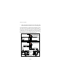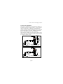
1
Installation & Maintenance Instructions
Loop Powered
Dewpoint Transmitter
Reading Office
Aberdeen Office
Cutbush Park, Danehill, Lower Earley,
Reading, Berkshire. RG6 4UT. UK.
Tel: +44 (0)118 9311188
Email: [email protected]
Unit 6 Airside Business Park, Kirkhill Industrial Estate,
Dyce, Aberdeen. AB21 0GT. UK.
Tel: +44 (0)1224 725999
Email: [email protected]
Internet: www.able.co.uk
e-procurement: www.247able.com
Registered in England No: 01851002
VAT No: GB 417 2481 61
LPDT User’s Manual
When calling your representative for technical support,
please have your serial numbers available.
The Sensor and Instrument Serial Numbers are on the
instrument, also see section 3.4.4.4.
Sensor Serial No.: _______________
Instrument Serial No.: _______________
Your Representative is:
Except as may be provided by contract, this document and all
specifications and drawings contained are the property of Xentaur Corporation, are issued in strict confidence, and shall not
be reproduced or copied or transmitted, in any form or by any
means, or used as the basis for the manufacture or sale of apparatus, programs, or services without permission.
Check the Internet for updates; the latest revision of this
manual is available in Adobe Acrobat format at:
http://www.xentaur.com
Document No.: LDO.01.D.2000 Rev.0 6/1/99
Copyright © 1999 by Xentaur Corporation
i
LPDT User’s Manual
Xentaur reserves the right to change or modify the product
specification and / or appearance at any time without notice.
Therefore, the information in this document is subject to
change without notice and does not represent a commitment
on the part of Xentaur Corporation.
The customer agrees that in accepting and using this instrument Xentuar Corporation’s liability arising from or in any
way connected with this instrument shall be limited exclusively to performing a new calibration or replacement or
repair of the instrument or sensor, at Xentaur’s sole option,
as covered by Xentaur’s warranty. In no event shall Xentaur
be liable for any incidental, consequential or special damages of any kind or nature whatsoever, including but not
limited to lost profits arising from or in any way connected
with this instrument or items hereunder, whether alleged to
arise from breach of contract, express or implied warranty,
or in tort, including without limitation, negligence, failure to
warn or strict liability.
Swagelok, Cajon are trademarks of SWAGELOK Co.
Acrobat is a trademark of Adobe Systems Incorporated
Microsoft Windows is a registered trademark of Microsoft Corporation
HTF is a trademark of Xentaur Corporation
SpanCheck is a trademark of Xentaur Corporation
The Xentaur Logo is a trademark of Xentaur Corporation
ii
LPDT User’s Manual
Examine the LPDT package for damage or mishandling. If any damage is evident notify the carrier
and request an inspection.
Unpack the box, it should contain: The LPDT with
sensor in desiccant container, connectorized cable,
and this manual.
PLEASE READ THIS MANUAL IN WHOLE,
PRIOR TO INSTALLING OR REMOVING THE
SENSOR FROM ITS SHIPPING CONTAINER.
This manual is organized in three sections:
Section 1 is an overview of the LPDT.
Section 2 describes the sensor and sampling techniques.
Section 3 describes the instrument’s electrical,
mechanical, and user interfaces.
This manual is intended for those already familiar
with the installation, use and maintenance of analytical or process instrumentation.
Those acquainted with other Xentaur dewpoint
measurement products such as the XDT or the
XPDM, will benefit from the commonality of the
user interface.
iii
LPDT User’s Manual
Warranty
Xentaur instruments are warranted to be free from defects in
workmanship and materials. Liability under this warranty is limited to servicing, calibrating, and replacing any defective parts of
the instrument returned to the factory for that purpose. Fuses are
specifically excluded from any liability. This warranty is effective
from the date of delivery to the original purchaser. The equipment
must be determined by Xentaur to have been defective for the
warranty to be valid. This warranty applies as follows:
• one year for electronics
• one year for mechanical failures to the sensor
• six months for calibrations
If damage is determined to have been caused by misuse or abnormal conditions of operation, the owner will be notified and
repairs will be billed at standard rates after approval.
Maintenance Policy
In cases when equipment fault is suspected, please notify your
representative of the problem, be sure to provide them with model
and serial numbers. If the problem can not be resolved, then ask
for a Return Authorization Number (RAN) and shipping instructions. Issuance of an RAN does not automatically imply that the
equipment is covered by our warranty, that will be determined
after we receive the equipment. Pack the equipment in a suitable
box with sufficient padding, include the RAN number on your
paperwork, and send the equipment, prepaid, to the designated
address. Xentaur will not accept equipment returned without an
RAN, or with reversed shipping or import/export charges.
If the warranty has expired, or the damage is due to improper use
or exposure of the equipment; then Xentaur will provide an estimate and wait for approval before commencing repairs.
For your convenience a Return Authorization Request Form is
provided in appendix J, it must be filled out and sent back to Xentaur in order to obtain a RAN.
iv
LPDT User’s Manual
LPDT User’s Manual Table of Contents
1.0 Overview of the LPDT .................................................1
2.1 Precautions using the sensor .........................................3
2.2 Sensor Technical Specifications ...................................4
2.3 Sensor Installation & Sampling Techniques .................4
2.3.1 In-situ Installation ......................................................5
2.3.2 Extractive Installation ................................................7
2.4 Troubleshooting unexpected readings ..........................9
3.1 Precautions using the LPDT .......................................13
3.1.1 Electromagnetic Compatibility Considerations .......13
3.2 Instrument Technical Specifications ...........................14
3.3 Installation ..................................................................15
3.3.1 Mechanical Installation ............................................15
3.3.2 Electrical Installation ...............................................16
3.4 Operating the Instrument ............................................17
3.4.1 Starting up ................................................................17
3.4.2 Display Conventions ................................................17
3.4.3 Push Buttons ............................................................19
3.4.4 Operating State ........................................................19
3.4.4.1 Viewing Dewpoint Mode ......................................20
3.4.4.2 Viewing Temperature at the Sensor ......................20
3.4.4.3 Start Calibration (SpanCheck™) Mode ................21
3.4.4.4 Viewing Serial Number Mode ..............................24
3.4.5 SetUp State ..............................................................24
3.5 Troubleshooting the Instrument ..................................28
Appendix A: Operating State User Interface flowchart ....31
Appendix B: Set-Up State User Interface flowchart .........32
Appendix C: LPDT Mechanical Drawing ........................34
Appendix D: LPDT Electrical Connections .....................35
Appendix E: Sensor/SpanCheck™ Theory of Operation .36
Appendix F: Pressure Correction ......................................39
Appendix G: Current vs. Dewpoint ..................................40
v
LPDT User’s Manual
Appendix H: Uncertainty in LBS & ppmV calculations ..43
Appendix I: Sensor Response Time ..................................44
Appendix J: Return Authorization Request ......................45
vi
Section 1: Introduction
1.0 Overview of the LPDT
The LPDT is a microprocessor based 4-20mA loop powered
(2 wire) hygrometer, for measuring moisture content in
gases in the range from -100°C to +20°C. The measurement
is displayed on the instrument’s custom LCD, and is transmitted by varying the current drawn (4-20mA) from the
power supply. The current varies linearly proportional to the
selected measurement units. An optional digital output is
available which modulates/demodulates the 4-20mA loop
line without interfering with its operation. With this option
the LPDT is capable of communicating with properly
equipped Personal Computers or other RS-232 capable controllers. Three front panel buttons provide the user with a
wide variety of features. The LPDT’s advanced design
allows it to be housed in a small stainless steel enclosure
behind the sensor probe, thus the instrument and sensor are
a single integrated unit.
The LPDT uses the Xentaur HTF™ sensor which is encapsulated in sintered stainless steel, thus it is capable of coming into contact with a wide variety of environments.
However one should keep in mind that the sensor is a sensitive device and it should be handled accordingly.
page 1
LPDT User’s Manual
page 2
Section 2: Sensor and Sampling Techniques
2.1 Precautions using the sensor
The Xentaur HTF™ Al2O3 sensor is designed and field
proven to be highly reliable, rugged and maintenance free.
However the user should consider the following precautions:
• To avoid the need for prolonged dry-down (when
expecting to measure dewpoints dryer than -65ºC), do
not expose the sensor to room air longer than necessary
(1 - 2 minutes). Thus, do not open the sensor container
before you are ready to install the sensor.
• The sensor container has desiccant to keep the sensor
dry during shipping and to avoid damage due to condensation. Close the container immediately after removing
the sensor to avoid degradation of the desiccant.
• Do not throw away the sensor container, you may use it
again to transport the sensor between locations, to store
it between uses or to ship it back to the factory for certification. The container can be attached to the loop cable,
by trapping the cable with the lid strap.
• Do not expose the sensor to corrosive gases such as
gases containing chlorine, ammonia or HCl. (SO2 can
be monitored when the moisture content is low).
• Except for the XTR65W sensor:
1. Do not expose the sensor to liquid water, as it may get
damaged.
2. Do not breathe directly onto the sensor, as condensation may form which could damage the sensor element.
• Do not install the sensor near heat sources such as radiators or air ducts.
• Do not install the sensor in places subject to extreme
mechanical vibration or shock. If this is not avoidable,
use resilient mounting. If in doubt, call your representa-
page 3
LPDT User’s Manual
•
•
tive.
Do not disassemble the porous metal filter encapsulation, as this will damage the sensor and void your factory warranty.
Prior to installation of the probe, ensure that no contaminants are present in the system (e.g. oil, liquid water).
2.2 Sensor Technical Specifications
Type: .................................Hyper Thin Film high capacitance Al2O3 .
Dewpoint range:
XTR-100 ........................-148°F to +68°F (-100°C to +20°C)
XTR-65 ..........................-85°F to +68°F (-65°C to +20°C).
Capacitance:......................15nF to 200nF.
Accuracy: ..........................±5.5°F (±3°C).
Repeatability: ....................±0.9°F (±0.5°C).
Response time: ..................see graph in Appendix I.
Temperature range: ...........-10°C to +70°C.
Sample Flow range:
(linear velocity @ 1ATM):Static to 100m/s.
Storage temperature: .........-40°F to+176°F (-40°C to +80°C).
Mechanical:.......................encapsulated in 100µ sintered stainless steel.
Calibration method: ..........SpanCheck™, sensor saturates at dewpoint above
+68°F (+20°C). NIST/NPL traceable multi-point
factory calibration available optionally.
2.3 Sensor Installation & Sampling Techniques
Keep in mind that the moisture content at the sensor is not
only due to the moisture of the gas being measured, but also
due to desorption of water from tubing, trapped moisture (at
the interconnection points, valves, filters and other hygroscopic materials in the system), leaks in the system, and others. Thus the measurement may vary from the expectation,
and therefore care should be taken in choosing the sampling
technique utilized in the measurement. Factors such as gas
pressure, flow rate, materials of construction, length and
page 4
Section 2: Sensor and Sampling Techniques
diameter of tubing, number of interconnecting fittings, dead
space in tubing and manifolds; will influence the measurement value and response time.
The high capacitance HTF™ sensors can be installed either
directly in the line to be sampled (in-situ), or in a slip stream
of a sample system (extractive).
To assure a long and accurate performance of the sensor, it
should be protected from contaminants such as liquids
(water, oil etc.), and particulates. The sintered stainless steel
sensor encapsulation protects from particulates larger than
100 microns, finer particulates (e.g. from degraded desiccant or rust) should be filtered with a particulate filter with
suitable capability, do not use hygroscopic filter materials.
2.3.1 In-situ Installation
In-situ installation is recommended only for measurements
where the gas pressure is expected to vary little, the gas is
expected to be free of contaminants, the gas temperature is
within the operating specifications of the sensor, and there is
no chance of liquids coalescing. Examples of applications
suited for in-situ installations are: pure gases, output of desiccant dryers (for instrument air), glove boxes, etc. For most
other applications in-situ installation should be avoided for
the following reasons:
• Sample conditioning is almost always necessary to
avoid exposure of the sensor to liquid water and other
contaminants, such as hydrocarbons, which may damage the sensor or affect accuracy over time.
• Variations in line pressure affect the reading of the sensor because dewpoint varies with pressure.
• If the gas line is under pressure, it is more likely that
water condensation occurs which may damage the sensor.
page 5
LPDT User’s Manual
•
Under a pressurized system removal of the sensor without the installation of isolation valves can be dangerous.
If in-situ installation is required, bypass mounting is preferable; make sure to install the sensor at the upper surface of
the gas line to minimize its exposure to liquid water, should
condensation occur, the XTR65W sensor is best suited for
these applications. Also consider the need to isolate (depressurize) before installing or removing the sensor.
4-20mA loop cable
LPDT
oint Transmitter
Think
Safety
In-Line Installation, Sensor
Measuring at Line Pressure
Mo
Se
Read
ual
Man
www.xentaur.com
Ma
NOT RECOMMENDED
Main
Gas Line
4-20mA loop cable
LPDT
oint Transmitter
Think
Safety
Mo
Se
Read
ual
Man
www.xentaur.com
Ma
Bypass Installation, Sensor
Measuring at Line Pressure
Sample Cell
Safety shut-off Valve
Main
Gas Line
Safety shut-off Valve
Bypass
Control
Valve *
* maintain differential pressure to provide adequate flow through sample cell
page 6
Section 2: Sensor and Sampling Techniques
2.3.2 Extractive Installation
For extractive installations we recommend our sample system ESS, which may be equipped with a variety of features,
such as: isolation valve, coalescing or particulate filter,
pressure regulator, calibration sample injection or extraction
port, pressure gauge, flow meter, weatherproof enclosure.
Refer to the ESS literature for more information.
If the resources to make your own sample system are available, the following two diagrams may be used as a guideline
to configure a simple system.
Exhaust
4-20mA loop cable
LPDT
Think
Safety
ual
Man
Main
Gas Line
Extractive Installation, Sensor
Measuring at Line Pressure
4-20mA loop cable
LPDT
oint Transmitter
Think
Safety
Sample Cell
Regulator or
Needle Valve
Mo
Se
Read
ual
Man
www.xentaur.com
Main
Gas Line
Ma
Sample Cell
Safety shut-off Valve
Mo
Se
Read
www.xentaur.com
Regulator or
Needle Valve
oint Transmitter
Ma
Exhaust
Extractive Installation, Sensor
Measuring at Ambient Pressure
page 7
LPDT User’s Manual
It is generally recommended to measure at ambient pressure
for the following reasons:
• The readings will not be affected by variations in line
pressure.
• The risk of exposing the sensor to liquid water is significantly reduced.
• ppm readings are computed for a pressure of one atmosphere (1 bar); and have to be corrected using software
in the instrument, or a pressure nomograph, or calculator if the sensor is measuring at different pressures.
If readings at line pressure are necessary, it is recommended
to measure at ambient pressure and to use the instrument’s
pressure compensation feature to calculate the dewpoint at
line pressure. See appendix F.
Please make sure that:
• The sample is taken from the upper surface of the main
gas line. This avoids problems with contamination. The
sample should be taken away from pipe line walls where
flow rates may be low, and dewpoint changes may lag.
• For dewpoints dryer than -40°F, use stainless steel tubing only. Copper tubing is acceptable for dewpoints wetter than -40°F. Do not use plastic, rubber or tygon tubing
under any circumstances, as measurements would be
incorrect and/or response time slow due to water retention inside these materials.
• Try to run pipes to the sensor upwards, so that contaminants tend to fall back into the main line.
• Keep the length of the sample line to the sensor as short
as possible.
• Use small diameter pipes (1/4” or 1/8” OD).
• Use sufficient flow rates (e.g. 1 l/min with 6 feet of 1/8”
piping is adequate). The flow rate will influence the systems’ response time.
page 8
Section 2: Sensor and Sampling Techniques
•
•
•
•
Do not install any devices upstream of the sensor, such
as other measuring systems, flow meters etc., which are
not absolutely necessary as these are potential leak
sources.
Installation of a coalescing and / or particulate filter
ahead of the sensor is desirable to prevent any liquid or
particulate contamination of the sensor.
If filters are used upstream of the sensor, make sure
these contain non-hygroscopic filter materials only.
If pressure regulators, shut off valves etc. are used
upstream of the sensor, make sure these do not contain
rubber or other hygroscopic materials.
2.4 Troubleshooting unexpected readings
If erroneous readings are suspected on a newly acquired
instrument, compare the serial number engraved on the sensor sintered filter, to the one stored in the instrument memory. The two should be the same; if they are not, the
instrument may not be calibrated with the installed sensor.
To troubleshoot other problems, identify the unexpected
reading category in the following table, and consider the
possible causes and appropriate diagnostic action and remedy.
page 9
LPDT User’s Manual
Troubleshooting unexpected readings (table spans 2 pages)
Symptom
Reading is not
changing
Possible Cause
Condensation in sample system.
Slow Response
Dry Reading
1. Water vapor in the system.
2. Flow rate too low.
3. Sample pipe too large and/or too long.
4. Unsuitable sample pipe material.
5. Leaks
6. Hygroscopic materials in sample system
SpanCheck™ wrongly set, or faulty sensor.
Leak in system or use of unsuitable pipe.
Wet Reading
Comparison of readings with manual cooledmirror instrument.
Display Shows
Prolonged exposure to wet gas.
Display Shows
1. Instrument Failure
6$7
6+5
2.Short circuited sensor.
Display Shows
231
1. Instrument failure.
2. Open circuit on sensor.
For non-sensor related problems (e.g. no reading on instrument) refer to section 3.5
page 10
Section 2: Sensor and Sampling Techniques
Troubleshooting unexpected readings (continued from previous page)
Symptom
Diagnostic/Remedy
Reading is not
changing
Condensation will occur if the temperature of the sample system, at any point is below
(colder) the dewpoint temperature of the sample gas. Once having formed, the sample
reaching the sensor will have a dewpoint equal to the temperature of the condensation,
regardless of the dewpoint of the sample at the sample point.
Slow Response
It is usually more satisfactory to bleed a sample gas at atmospheric pressure through
the sensor sampling chamber, and to use 1/8” (3mm) o.d. sample pipe.
See below re: sample pipe material, also see section 2.3
Dry Reading
Verify SpanCheck™, or return sensor for full calibration to your representative.
Wet Reading
Cure the leak, or replace unsuitable pipe with copper or stainless steel. Flexible connections should be made with PTFE pipe. NEVER use rubber or plastic pipe.
This type of indicator reads about 10°C dry at about -50°C dewpoint due to temperature gradients within the device. The error increases at drier levels.
Display Shows
Dry the sensor, install sensor in either a known dry gas stream i.e. instrument quality
air or dry nitrogen, or place sensor in a dry can or bottle of desiccant and seal the container from outside air (the shipping container is designed for this purpose)
Display Shows
Remove (unscrew) sensor, if the instrument still reads 6+5 the problem is with the
instrument. However, if the instrument reads 231 then check possible cause #2
6$7
6+5
Remove (unscrew) sensor and note that the meter reading returns to 231. Use a new
sensor, or apply approximately 20V DC, between the center pin & the filter body of
the sensor, MOMENTARILY with the sensor in a known dry condition. Polarity is not
important, but the contact MUST be very brief or the sensor may be damaged.
Display Shows
231
Remove (unscrew) the sensor. Short the center contact of the LPDT sensor connection
to the case, if the instrument reads 6+5 the problem is in the sensor, otherwise return
the instrument for service.
Check sensor connection or replace sensor.
page 11
LPDT User’s Manual
page 12
Section 3: Instrument
3.1 Precautions using the LPDT
The LPDT uses state-of-the-art microelectronics to provide
a miniature full functioning instrument. The user should
consider the following precautions when using any sensitive
electronic device.
• Do not install the unit near heat sources such as radiators or air ducts.
• Do not install the unit in places subject to extreme
mechanical vibration or shock. If this is not avoidable,
use resilient mounting. If in doubt, call your representative.
• Observe the appropriate electrical safety codes and regulations
• If weather proofing is required consult your representative for an optional cover.
3.1.1 Electromagnetic Compatibility Considerations
The LPDT has been designed and verified by testing to
meet the requirements of the EC Council EMC Directive
89/336/EEC, for Industrial, Scientific & Medical equipment. The sensor ground (LPDT housing) is isolated from
the 4-20mA loop, however they are also shunted with a
2000pF capacitor and a 33V Transient Voltage Suppressor;
this prevents electrostatic buildup, noise pick-up, and in
conjunction with the internal fuse protects the instrument
from over-voltage inputs. Please consider the following
electromagnetic interference issues during installation:
• In order to provide an acceptable noise environment for
the LPDT or any other digital equipment in the proximity of inductive loads, it is recommended that there be
varistors placed across the inductors to keep down the
high voltage spikes during transitions.
page 13
LPDT User’s Manual
•
•
Any circuitry which is activated by relay contacts
should account for the contact bounce, one simple
debouncing method is placing a capacitor across the
relay contacts.
AC power wiring should be routed as far away from the
LPDT and its wiring as practical.
3.2 Instrument Technical Specifications
Enclosure: .........................Stainless Steel, optional weather proof cover is available.
Dimensions & Weight:......~2”Dia. x ~4.75” long including sensor & connector
(see appendix C) 0.5lbs.
Pressure operating range: ..Standard: .....500 PSI (34 bar).
Optional: .....5,000 PSI (340 bar).
Mechanical connections:...14mm x 1.25mm threads, and ¾”-16 threads.
Electrical connections: ......2.1mm x 5.5mm (12mm minimum barrel length)
power jack, with retainer.
Cable: ................................Two conductor cable, 12’ (~4m) provided.
Power Requirements: ........10 to 33 VDC polarity independent, the instrument
draws 4-20mA depending on measured dewpoint.
Input resolution: ................0.1°C dewpoint.
Indicators: .........................3.5 digit LCD with custom legends.
Engineering units: .............°C,°F, PPM, LBS H2O/mm scf,gm H2 O/M3.
Controls:............................3 push buttons, user’s selections are stored in
EEPROM.
Outputs:.............................Analog and digital outputs are available from the
LPDT.
A. 4-20mA drawn by the instrument from the power
supply. The 4-20mA is linear to the selected engineering units, the range is programmable. Output
resolution is 0.1°C dewpoint.
B. The instrument can supply digital output by
modulating the 4-20mA loop line. The timing and
format of the data conforms to RS-232, however to
interface to a PC or other RS-232 device an optional
adapter is required.
In the digital mode the LPDT can be remotely
operated and the dewpoint as well as temperature
page 14
Section 3: Instrument
(and pressure if installed) can be read.
In the digital mode multiple units can operate on
the same loop cable as a multi-channel instrument.
Alarms:..............................The 4-20mA signal or the digital output may be used
by an external device to operate relays.
Isolation: ...........................Sensor and case are isolated from the current loop
but are shunted with a 33V transorb and 2000pF
capacitor.
3.3 Installation
3.3.1 Mechanical Installation
The LPDT has two thread sizes for mounting to the sample
cavity (consult the sensor installation section) where the
dewpoint will be measured. Various adapters are available
for direct connection into existing system openings. Ask
your representative for a Sample Cell, if you do not have the
ability to provide an appropriate sample cavity mounting. If
the ¾”x16 thread is used then the LPDT will seal against the
wall of the sample cell with the provided Viton A O-ring. If
the 14mm x 1.25 spark plug thread is used then an additional Viton gasket must be installed to provide the proper
seal. Ask your representative for this gasket, it is available
free of charge. The LPDT is light enough such that either
thread will mechanically support the whole instrument. To
prevent any leaks, tighten the LPDT into the sample cavity,
with a 17/8” wrench, 1/8 turn past finger-tight to assure
metal-to-metal contact.
Since the tightened positioning of the LPDT is unpredictable, its front panel may be rotated (360°) to allow easy
reading of the display. Press down gently on the spring
loaded face plate and turn it to the desired position.
The sensor can be removed from the LPDT by unscrewing
it. Make sure that the sensor is securely fastened to the
page 15
LPDT User’s Manual
LPDT (the tension washer should be compressed), so that it
does not come loose during use.
3.3.2 Electrical Installation
The LPDT will operate properly with 10VDC to 33VDC at
its input, if this voltage is exceeded the internal fuse may
blow. When selecting the power supply voltage do not
neglect the drop across any current measurement resistor
and wiring in the loop. The connector is a standard 2.1mm x
5.5mm (12mm minimum barrel length) DC power jack, an
internal diode bridge accommodates either polarity. The
LPDT may be powered using an off-the-shelf wall transformer with 2.1mm connector, or from a power supply
using the provided connectorized cable. The provided cable
is terminated with a connector which has a retainer, the
retainer may be used to secure the connector to the LPDT
thus avoiding accidental disconnection.
The LPDT will draw 4mA to 20mA from the power supply
depending on the dewpoint being measured. The dewpoints
corresponding to 4mA and to 20mA are user selectable, in
between the current will vary linearly to the selected engineering units, see appendix G.
Various strategies for interfacing with the LPDT are shown
in Appendix D.
Please observe good electrical safety and grounding practices when connecting any electrical equipment; connecting
one end (e.g. negative) of the power supply to earth ground
is advisable.
After the installation is complete, proper detection by the
user’s equipment of the 4-20mA output, may be tested using
the Analog Output test feature of the LPDT, see section
3.4.5.6.
page 16
Section 3: Instrument
3.4 Operating the Instrument
3.4.1 Starting up
The instrument is ready for use as soon as the power cable is
installed. When power is applied the instrument will initialize its program and for a moment display ;(1, then it will
enter the Operating State. If the MODE button is held
pressed while the instrument is performing its power-up initialization, it will enter the Set-Up State, which allows the
user to select operating variables of the instrument.
To accommodate a variety of installation possibilities, the
LPDT front panel may be rotated (360°) by gently pressing
down on the spring loaded face plate and turning it to the
desired position.
3.4.2 Display Conventions
1. To display characters with the 7 segment numeric display, the following pseudo-alphanumerics are used:
Numbers:
0 12 3 4 5 6 7 8 9
Letters:
ABCDEF GH IJ LNOP QRS TUXYZ
$ % & ' ( ) * + , - / 1 2 3 4 5 6 7 8 ; < =
Symbols:
? - .
" 2. The instrument will indicate whether a particular mode
lets you change a parameter by showing the word
“SET” in the upper left corner of the display. Be careful
page 17
LPDT User’s Manual
not to change any parameter inadvertently.
3. °C°F appear simultaneously, to indicate the sensors’
attenuation in decibels.
4. Values larger than ±1999 or smaller than ±0.01 are displayed in powers of 10±3. As required, either a “10 3” or
“10-3” will appear above and to the right of the displayed value, the value will be rounded off to 3½ digits.
The display will show 51* (out of ranGe), if the number to be displayed is larger than 1,999,000. Twelve
examples follow; for each the number and units desired
to be displayed are shown in italics, depicted immediately below them is the resultant 3½ digit LCD display:
1104.2
+20°C
+68°F
lbs H O/mmSCF
23,612 ppmV
2
x10 3
PPM
˚C
˚F
DEWPOINT
DEWPOINT
DEWPOINT
DEWPOINT
LBS
17.688
3
grams H O/meters
2
-100°C
2,000,000
-148°F
˚C
DEWPOINT
G/M3
0.013,849
ppmV
DEWPOINT
0.000,921,15
0.000,014,75
lbs H O/mmSCF
grams H O/meters
2
x10 -3
3
2
x10 -3
x10 -3
PPM
DEWPOINT
˚F
DEWPOINT
DEWPOINT
LBS
DEWPOINT
page 18
G/M3
0.000,000,1
Section 3: Instrument
3.4.3 Push Buttons
Three push buttons are located on the front panel.
XENTAUR
SET %
HILO
TEMP
DEWPOINT
MODE button
LPDT
PSI
G/M³
UP button
x10¯³
PPM
˚C˚F
LBS
DOWN button
Each button is marked with an icon engraved above it.
In general the MODE button navigates through the different
user options “Modes”; the UP and DOWN buttons modify
the units, values or choices in the selected mode. Refer to
the flow diagrams in Appendix A for detailed overview of
button functionality. A button may be held down for a prolonged time, for accelerated incrementing or decrementing
of numeric values.
3.4.4 Operating State
Upon power up, the unit performs certain initialization tests
(see table in section 3.5), and enters the ‘Operating State’, in
the Viewing Dewpoint mode. Depressing the ‘MODE’ button will change modes (see appendix A) in the following
order: nViewing Dewpoint ‹ oViewing Temperature ‹
pStart Calibration ‹ qViewing Serial Number ‹ (back to)
nViewing Dewpoint. The unit will return to Viewing Dewpoint mode if no buttons are pressed for 30 seconds, unless
it is performing a calibration.
page 19
LPDT User’s Manual
3.4.4.1 Viewing Dewpoint Mode
In this mode the user can view the dewpoint, this is indicated by the presence of the ‘DEWPOINT’ legend on the
lower left of the display. The available engineering units in
which to view the moisture content are °C, °F, PPM, LBS
and G/M3; the UP and DOWN buttons scroll back and forth
through these units in respective order. The °C and °F are
dewpoint readings. The PPM is parts per million by volume
computed at the sensor pressure (more about pressure in
appendix F). The LBS and G/M3 are pounds of water per
million standard cubic feet and grams of water per standard
cubic meters, both in Natural Gas, they are computed
according to data derived by IGT Research Bulletin 8, taking into account sensor pressure.
Note that the analog output is linear to the selected engineering units, therefore be mindful that while scrolling
through various units the analog output may change even
though the measured dewpoint is stable.
The PSI legend flashes at the bottom of the display, when
there is pressure correction in the computation of the displayed values, refer to appendix F.
3.4.4.2 Viewing Temperature at the Sensor
In this mode the user can view the thermodynamic temperature at the dewpoint sensor inside the sampling chamber,
this is indicated by the flashing ‘TEMP’ legend on the lower
left of the display. The available units in which to view the
temperature are °C and °F. The UP and DOWN buttons
switch back and forth between these units.
Pressing the MODE button changes to the Start Calibration
Mode.
page 20
Section 3: Instrument
3.4.4.3 Start Calibration (SpanCheck™) Mode
The instrument is calibrated at the factory with the sensor it
is shipped with and does not need to be re-calibrated prior
to installation.
Instrument calibration is recommended in approximately 12
month intervals, and the XTR65W sensor should be re-calibrated after prolonged exposure to liquid water. Simply follow steps 1 - 7 of the procedure below, removing the sensor
from the sample gas stream. Make sure the gas stream is
depressurized before removing the sensor to avoid injury.
It is recommended to keep the sensor exposure to room air
as short as possible to avoid super saturation of the sensor.
While super saturation is not damaging to the sensor, it will
prolong the initial dry-down time after you install the sensor
in the sample stream. Therefore, remove the sensor from the
packaging container only after you are ready to proceed
with the calibration procedure and install the sensor in the
sample stream immediately after the calibration procedure
is completed. If you are not ready to use the sensor right
away after calibration, put the sensor back in the shipping
container for dry storage.
The instrument must be calibrated with the sensor it will be
used with. The calibration procedure takes advantage of the
designed saturation level (DSL) feature of the sensor and is
executed by the instrument computer, by performing the following steps:
1. If the instrument is locked and a calibration is
attempted; it will display /2& and will not perform the
calibration. To unlock the instrument consult section
3.4.5.9.
page 21
LPDT User’s Manual
2. Push the MODE key a few times until the display shows
&$/.
3. Press the UP button. The display will show &1), prompting you to confirm that you want to start the calibration
procedure. You can abort the calibration procedure by
pressing the MODE key.
4. Remove the sensor from its packaging container so that
the porous metal filter is visible and the sensor is
exposed to in-hand micro-climate. Close the packaging
container as soon as you have removed the sensor to
avoid degradation of the desiccant inside of the container. You may want to re-use the container at a later
date.
5. Push the UP button again to confirm that you want to
start the calibration procedure. The display will flash $&
for 60 seconds, while the sensor is saturating. Make sure
you keep the sensor exposed to in-hand micro-climate
until the display shows (1'.
6. After 60 seconds, the display will flash the selected sensor type (see “Selecting a sensor type 3.4.5.2”) and then
the instrument will calculate the slope and offset of the
sensor curve while displaying the calculations and then
will display (1' for a few seconds, after which the
instrument will automatically go into measuring mode.
The sensor calibration is completed. (The display may
flash6$7, indicating that the sensor has super-saturated.
As soon as the sensor is exposed to an atmosphere with
a dewpoint lower than the saturation dewpoint, the display will indicate the dewpoint measured by the sensor.)
The display may show alternating6(1and/2as an
indication that the measured capacitance is too low to be
from a saturated sensor, in this case make sure that the
sensor is fully engaged into the LPDT, and repeat the
page 22
Section 3: Instrument
calibration procedure.
7. Install the sensor in the sample cell or adapter fitting or
put it back into the packaging container for later use.
The instrument will retain the calibration even if the power
is turned off.
Under certain conditions, an over (super) saturated sensor
may need to be completely dried out before a calibration is
performed. Symptoms of these conditions are a sensor that
will not go through the SpanCheck™ function to the (1'
display, or a sensor that will not dry down after calibration.
To dry, install sensor in either a known dry gas stream i.e.
instrument quality air or dry nitrogen, or place sensor in a
dry can or bottle of desiccant and seal the container from
outside air (the shipping container is designed for this purpose). After a minimum dry out period of 24 hours, proceed
with the calibration procedure of your choice.
SpanCheck™ calibrates sensors by using micro climates.
Please contact your representative if you have any questions
about how to create such micro climates.
A perfectly acceptable and accurate for calibration microclimate may be created for the XTR100 and XTR65 sensors
by cupping the sensor in the palm of one’s hand during the
SpanCheck™ procedure. Remember that the micro-climate
does not have to be accurate, it just has to be higher than the
designed saturation level. The dewpoint of the micro-climate within the fingers is usually higher than the dewpoint
of the room air and probably well above the +20°C upper
range of the sensor. On a dry day one may need to exhale in
the hand before cupping the sensor to guarantee a high dewpoint. The sensor should be warmed up close to body temperature before performing this procedure. Care must be
page 23
LPDT User’s Manual
taken that the sensor temperature is not below the temperature of the hand, as in such case condensation could occur
and super saturate the sensor. For the same reason, avoid
exhaling directly onto the sensor.
3.4.4.4 Viewing Serial Number Mode
In this mode the user can view the serial number of the sensor calibrated and shipped with the instrument. This number
is also engraved on the stainless steel sintered filter of the
sensor element. The display shows the serial number by
alternately displaying ;61 and the number. If the number is
larger than 1999 then it is displayed in 2 parts, first part is
the thousands signified by the x103 legend in the upper right
corner of the display and the second part is the units. For
example serial number 12345 will be shown as:
XSN
12
x10 3
345
Pressing the UP and DOWN buttons simultaneously resets
the instrument, this is useful for restarting in the set-up state
(by holding the MODE button), in installations where
power can not be turned on and off easily.
Pressing the MODE button changes the unit to the Viewing
Dewpoint Mode.
3.4.5 SetUp State
To enter the Setup State power-up the unit (or reset it from
the serial number Mode), and hold the MODE key pressed
while the unit is initializing. Refer to Appendix B for a flow
page 24
Section 3: Instrument
diagram of the SetUp State.
The setup state provides nine capabilities, each one controlled from its own mode. Depressing the MODE button
navigates through the modes in the following order: nSelect Alternate Display Units ‹ oSelect Sensor Type ‹ pSet
Measured Attenuation of Sensor at a Low Dewpoint ‹ qSet
the Low Dewpoint at which the Attenuation was measured ‹
rSet the Calibration Mid-range Adjust ‹ sPerform a Test
and Verification of the Analog Output ‹ tSet dewpoint corresponding to 4mA of Analog Output ‹ uSet dewpoint corresponding to 20mA of Analog Output ‹ vLock/Unlock the
instrument ‹ (back to) nSelect Alternate Display Units.
These nine functions are explained in their respective sections which follow. Changes can be made only to an
unlocked instrument, the changes are stored (when the
MODE button is pressed) and retained even if the unit is
turned off.
1. Display of alternate units: In this mode, a second engineering unit can be chosen to be displayed alternating
with the engineering unit selected in the operating state,
for example, a dewpoint can be displayed alternating
with the sample temperature, or dewpoint can be alternately shown in °C and in PPM.
2. Selecting the sensor type: In this mode the user can
select the software matching the type of sensor installed
in the instrument; ;7 : XTR-100 (-100°C to +20°C);
;7 : XTR-65 (-65°C to +20°C).
3&4Adjusting low end sensor attenuation and dewpoint:
These modes are used to enter a data pair representing a
low dewpoint and the sensor attenuation measured at
this low dewpoint. (see Sensor Theory of Operation
appendix E). This data pair should not be modified
unless the sensor is replaced. The sensor shipping con-
page 25
LPDT User’s Manual
tainer is labeled with the proper values.
5. Calibration Adjustment: In this mode the user can
enter a sensor specific Adjustment Value to improve the
instruments’ accuracy in the range of -50°C to -10°C,
this adjustment has very little or no effect outside this
range. The Calibration Adjustment Value is printed on
the shipping container supplied with the sensor, or may
be derived if the sensor can be exposed to a known reference.
① Deriving an Adjustment Value: If the adjustment
value for your sensor is not known, contact your representative and follow the instructions in paragraph B on
the next page. If the value is not available, then it may
be derived using a manual method, provided that a
moisture calibration lab is available.
The calibration must be done in the range of -25°C to
-20°C (attempting to calibrate outside this range may
cause inaccuracies), the dewpoint must be kept stable
during calibration and it must be measured accurately
by a reference instrument such as a chilled mirror. One
must also note the state of pressure compensation and
turn it on or off as applicable to the reference.
The necessary steps are described below (also refer to
the Set-Up State flow diagram in Appendix B):
a. Make sure that the low attenuation and low dewpoint
are correctly entered for this sensor.
b. SpanCheck™ the sensor.
c. Dry-down the sensor for at least 12 hrs.
d. Expose the sensor to the known dewpoint (-25°C to
-20°C), for a sufficient time (at least 30 min.)
e. Go to the &$/$'- mode and press the UP button, the
display will show the current value, in the range of -1.99
to +1.99 followed by blinking horizontal lines.
page 26
Section 3: Instrument
f. Observe the display, if the buttons are not being
pressed; the display will every few seconds show for a
short duration the dewpoint as being computed at the
moment (utilizing the current cal-adjust value in the
computation).
g. Use the UP or DOWN buttons to modify the caladjust value and observe the alternately displayed dewpoint. Perform this adjustment until the dewpoint
matches the value shown by the reference instrument.
h. Press the MODE button to go to the next mode, this
will save the new cal-adjust value, and it will be retained
even if power is turned off.
② Entering a known Adjustment Value: If the sensor is
being replaced an adjustment value should be supplied
with the sensor, to enter it into the instrument:
a. Go to the &$/$'- mode and press the UP button, the
display will show the current value, in the range of -1.99
to +1.99 followed by blinking horizontal lines, ignore
the alternately displayed dewpoint.
b. Use the UP or DOWN buttons to modify the caladjust value as necessary.
c. Press the MODE button to go to the next mode, this
will save the new cal-adjust value, and it will be retained
even if power is turned off.
2), 3), 4) and 5) are set at the factory and need only be
modified when a sensor is changed.
6. Testing the analog output: By pushing the UP or
DOWN buttons, the user forces the analog output to its
low and high values, respectively. This facilitates the
hook-up and testing of the user’s monitoring equipment.
7&8Output range setting: These modes are used to set
dewpoints corresponding to the low and/or high end of
page 27
LPDT User’s Manual
the current loop output, refer to appendix G.
9. Lock/Unlock the instrument: This mode is used to
block access to parameter settings, protecting the instrument from unauthorized or inadvertent changes of
parameters. Attempting to change settings while instrument is locked will display /2&
To unlock the instrument press the UP button, to lock
the instrument press the DOWN button. Pressing the
MODE button will navigate back to the Select Alternate
Display Units mode.
Pressing and holding either the UP or DOWN button,
will save the lock or unlock setting depending on the
button, and reset the instrument. This feature is useful if
it is difficult to power off the instrument.
Note: It is imperative that one returns the instrument to
the locked mode to avoid unauthorized changes.
3.5 Troubleshooting the Instrument
This instrument performs diagnostic tests on power up as
well as once every two minutes. The table that follows,
depicts all possible error/unexpected messages that may be
displayed on the instrument. For each message the table has
explanations for the reason, and if necessary a suggested
action to remedy it.
page 28
Section 3: Instrument
DISPLAY
EXPLANATION
REQUIRED ACTION
PROM check sum failed.
HI(55
RAM write/read test failed.
%(55
Unidentified power-up failure.
&6)
EEPROM Check Sum Failed.
return to your representative
(55$'
A/D converter failure.
for service.
(555()
Reference voltage for A/D out of spec.
/2%$7
Low supply voltage.
LO51*
TEMP
Instrument low temperature range
has been exceeded.
HI51*
TEMP
Instrument high temperature range
has been exceeded.
6$7
Sensor is saturated.
6+5
Sensor circuit is shorted.
Trying to calculate dewpoint for
undefined sensor.
'%
Trying to calibrate an undefined
sensor.
system tests once per 2 min.
dewpoint display tests
Sensor circuit is open.
Calibration. tests
231
power on tests
LO(55
cycle power
if problem persists,
check input voltage 10-33VDC
make sure that the unit is at a
temperature of -10°C to +70°C.
see table in
sensor troubleshooting
section
select sensor and
SpanCheck.
see Calibration instructions.
Sensor reading is ‘too’ low to be a saturated sensor, for SpanCheck.
(55((3
EEPROM write cycle not completed.
if this persists, return for service.
/2&
Attempting to modify a locked unit.
unlock unit, see set-up mode.
51*
number can not be displayed in 3.5 digits.
°C(°F)
An XTR-65 sensor is measuring less
than -70°C or -94°F dewpoint.
w/flashing
DEWPOINT
PSI
Pressure correction is enabled.
;(1
Turn on message, Xentaur (Greek Ξ=X)
flashing
when dew
Legend:
denotes alternately flashing messages.
page 29
miscellaneous
6(1/2
LPDT User’s Manual
The instrument contains a fuse which may open if the
instrument is subjected to voltages exceeding the specifications. Under these circumstances the unit display will be
blank and the instrument will not draw any current when
powered up. The fuse is not user replaceable, therefore the
LPDT must be sent to your representative for servicing.
page 30
Appendices
Appendix A: Operating State User Interface flowchart
30 seconds anywhere
other than calibration
without a key press
XENTAUR
Viewing
Dewpoint
XENTAUR
LPDT
˚C
DEWPOINT
a flashing
PSI legend
means pressure
correction is
being applied,
see appendix F
LPDT
Cancel Calibration (calibration values are not changed)
Power ON initialization
and sign on message
CAN
1sec.
PSI
Confirm
SpanCheck™
select
units
XENTAUR
Viewing
Sensor
Temperature
XENTAUR
CNF/AC?
LPDT
˚F
TEMP
XENTAUR
1 minute
SET
select
units
Calibration
Menu
Sensor
Reading
XENTAUR
LPDT
SET
LPDT
AC/_AC
Too Low
LPDT
OK
2 sec.
SET
XENTAUR
LPDT
XENTAUR
SET
SEN/2LO
LPDT
c.
se
XENTAUR
SET
Press together to
RESET the Instrument.
Then quickly press and hold
MODE to go to Set-Up State.
LEGEND:
LPDT
New Calibration
Values Stored
1
XENTAUR
w s
fe ond
c
se
Viewing
Serial
Number
LPDT
SET
numbers calculating
calibration
1. Arrows leading out from below a button depict the flow as a result of
pressing the button.
2. Arrows leading out of other locations depict flow as a result of
completing a function or a time-out.
3. A slash ' /' in the display area, is used to depict two alternately
shown (flashing back and forth) messages.
page 31
page 32
A.O./RNG/
A.O./RNG/
DB/
SET
˚C
UN/LOC
A.0./TST
CAL/ADJ
DEWPOINT
SET
LO
˚C˚F
SEN/XT1
ALT/DSP
SET
LO
SET
SET
˚C
ppm
LBS
G/M3
PSI
%
˚C˚F
XT6
XT1
DB
/
SET
LO/BAT
Calibration Midrange Adjust
+/- 0.1˚C
+/- 0.01 units
If no buttons pressed
for 3 seconds the dew
is shown for a moment.
Set low dewpoint for the above set attenuation
+/- 0.01dB
Set measured attenuation at a known low dewpoint
XTR-65
XTR-100
attenuation
Factory default is blank (there is no alternate display).
˚F
Choose Sensor type
blank
Temp˚F
Temp˚C
LOC appears when changing
settings of a locked instrument
Choose alternate units to show when displaying dewpoint
Power-Up with
MODE key pressed
LPDT User’s Manual
Appendix B: Set-Up State User Interface flowchart
CAUTION! These parameters are set
properly at the factory, to correspond to
the shipped sensor. Do not modify them
unless you are replacing the sensor.
page 33
LEGEND:
A.O./RNG/
A.O./RNG/
DB/
Too
Low
LO/BAT
Ensure minimum voltage at LPDT
to be 10VDC, when drawing 20mA
DB
When locked instrument parameters can not be changed.
Factory default is locked.
Lock or unlock the instrument
+/- 0.1˚C
Factory default is 20˚C
Set dewpoint corresponding to high end of analog output
+/- 0.1˚C
Factory default is -100˚C
Set dewpoint corresponding to low end of analog output
Test
Current Loop
OK
Voltage
Test Analog Output
XT6
Lock
Unlock Prolonged press of either button will reset the unit
UN/LOC
˚C
˚C
4mA
20mA
A.0./TST
XT1
1. Arrows leading out from below a button depict the flow as a result of
pressing the button.
2. A slash ' /' in the display area, is used to depict two alternately
shown (flashing back and forth) messages.
SET
SET
HI
SET
LO
HILO
CAL/ADJ
SEN/XT1
ALT/DSP
Appendices
User Interface Flow Diagram - Set-Up State (continued from previous page)
tension washer
5/16"-24
Power Jack screw-on retainer
Think
Safety
Read
page 34
ual
Man
www.xentaur.com
Ma
1.850"
oint Transmitter
2.230"
14mm x 12.5mm
3/4"-16
Viton A O-ring
Removable Sensor encapsulated
in 100m sintered stainless steel,
unscrew to remove.
0.600"
flats for 17/8 " wrench
x10¯³
PPM
˚C˚F
LBS
G/M³
SET %
HILO
TEMP
DEWPOINT
PSI
LPDT
XENTAUR
DC Power Jack
front panel r
otat
es
fr
ee
ly
36
0˚
LPDT User’s Manual
Appendix C: LPDT Mechanical Drawing
1.750"
Se
Mo
Appendices
Appendix D: LPDT Electrical Connections
Methods of Using and Interfacing the LPDT
Operation with Wall Transformer
Dewpoint viewed on Instrument Display
Operation with Relay Option Board
Dewpoint viewed on Instrument Display
and available as 4-20mA output
m
er
10-33VDC
sf
or
120V
or
220V
lT
ra
n
oint Transmitter
Think
Safety
ual
Man
www.xentaur.com
W
al
Mo
Se
Read
Ma
Relay Option Board
Provides two
independent Relays
with programmable
trip point and
hysteresis
oint Transmitter
4-20mA
Think
Safety
Mo
Se
Read
ual
Man
Ma
www.xentaur.com
DC or AC supply
Operation with DC Power Supply
Dewpoint viewed on Instrument Display
and available as 4-20mA output
maintain
10-33VDC here
Operation with Remote Option Board
Dewpoint viewed on Instrument Display
and available on remote
oint Transmitter
Think
Safety
4-20mA
Mo
Se
Read
ual
Man
www.xentaur.com
Ma
VDC
Display
Buttons
Relays
Voltage or Current
Output
RS-232 Output
Power Supply
oint Transmitter
Think
Safety
Mo
Se
Read
ual
Man
Ma
www.xentaur.com
85 - 265VAC
Operation with Multichannel Option Board
Dewpoint viewed on each Instrument Display
and available on remote interface
Operation with DC Power Supply
Dewpoint viewed on Instrument Display
and available as Voltage output
oint Transmitter
Think
Safety
Mo
RS-232C
to Computer
Multichannel
Option Board
DC or AC supply
Se
Read
ual
Man
www.xentaur.com
Ma
multiple units connected on the same two wires
12-33VDC
Manu
al
Mo
r.c
Se
tau
en
w.x
ww
Read
er
om
om
r.c
Se
tau
Mo
al
itt
sm
k
in ty
Th fe
Sa
an
t Tr
Manu
en
w.x
ww
Read
er
itt
om
r.c
Se
tau
Mo
al
oin
ty
sm
k
in
Th fe
Sa
Manu
en
w.x
ww
Read
er
itt
a
M
a
M
a
M
page 35
an
t Tr
oin
ty
sm
k
in
Th fe
Sa
100W
an
t Tr
oin
0.4 - 2V output
LPDT User’s Manual
Appendix E: Sensor/SpanCheck™ Theory of Operation
The Sensor is constructed as a capacitor whose dielectric
consists of porous Aluminum Oxide as well as the gas that
has entered in the pores of the Aluminum Oxide. The plates
(electrodes) of this capacitor are an aluminum substrate and
a porous gold layer deposited on top of the Aluminum
Oxide, the porous gold electrode allows transfer of gases
into or out of the Aluminum Oxide pores.
The capacitance due to the Aluminum Oxide is always constant, while the capacitance due to the gas varies according
to the gas content and pressure. Since the dielectric constant
of water is orders of magnitude larger than that of any gases
being measured, the quantity of water vapor present in the
pores changes the capacitance of the sensor to a much
greater extent than any other system variable. For the same
reason (the extremely large dielectric constant of the water
molecule), any capacitance variations arising from the Aluminum Oxide, such as changes due to temperature, are
insignificant in relation to the capacitance due to the water
content. Thus the sensor capacitance varies greatly in proportion to the water content in the surrounding gas. The sensor is designed such that the relationship of the quantity of
water and the resultant capacitance has an "S" shaped curve.
At the extremely dry end the curve is asymptotic to the
capacitance due to the Aluminum Oxide and the gas, while
at the very wet end the curve is asymptotic to the capacitance due to water molecules packed extremely tightly (saturated) in the pores of the Aluminum Oxide. This upper end
is an excellent indication of the total pore volume; while the
lower end of the curve is an indication of the distance
between, and area of the capacitor plates (electrodes), this is
the intrinsic capacitance of the sensor. Therefore knowing
these two points, a sensor can be calibrated with compensa-
page 36
Appendices
tion for small manufacturing deviations.
As the sensor is used in real world applications, it is
exposed to various elements and stress; like any other sensor it may over time drift from calibration. However one
must note that the intrinsic capacitance will not change with
use because it is based simply on the dielectric constant of
Al2O3 and the distance between, & area of the plates (electrodes), thus the original factory measured values will
always be valid. What may change is the pore volume, due
to clogging with contaminants, residual oxidation, metal
migration, etc. Thus to re-calibrate the sensor the instrument
needs only to "know" the capacitance at the wet end of the
curve. As discussed previously the capacitance at the wet
end approaches asymptotically a saturated pore capacitance,
therefore if the sensor is saturated (the exact water content
will not be important since the curve is asymptotic), then the
instrument can measure the capacitance and re-calibrate the
sensor. This is refered to as SpanCheck™. The advantages
of this unique capability of Xentaur sensors and instruments
are obvious in time and cost savings for re-calibration, as
well as ease of sensor replacement.
Xentaur HTF™ Sensor: Dewpoint vs. Capacitance Response Curve
200
Saturated Capacitance Asymtote of New Sensor
Saturated Capacitance Asymtote of Aged Sensor
160
Curve
ew
Se
ns
o
r
enso
dS
Age
120
N
Capacitance (nF)
e
urv
rC
80
40
Dry Capacitance Asymtote of New & Aged Sensor
0
-80
-60
-40
-20
Dewpoint Reference ˚C
page 37
0
20
LPDT User’s Manual
page 38
Appendices
Appendix F: Pressure Correction
Sensor Pressure is used in the context that this is the pressure inside the sampling chamber when performing the
measurement, i.e. it is the operating pressure of the sensor.
Gas Pressure is used in the context that this is the pressure at
which the dewpoint is to be calculated.
Pressure Correction is used in the context that the values
displayed signify the moisture content at some pressure (we
refer to this as the ‘Gas Pressure’) different from the pressure at the sensor. Note that PPM, LBS and G/M3 readings
are by definition unaffected by pressure correction because
only the pressure at the sensor affects their value. While °C
and °F are affected by pressure correction by reporting what
the dewpoint would be at the Gas Pressure when the dewpoint is what is measured at the pressure at the sensor. However, this also implies that whether pressure correction is
applied or not the PPM, LBS and G/M3 readings are
affected by the setting of the sensor pressure.
The factory default settings are: 14.7psi for both sensor and
gas pressure and pressure correction disabled.
When Pressure correction is disabled all dewpoints are
computed by assuming that both Sensor and Gas Pressures
are 14.7psi.
As all Xentaur dewpoint meters, the LPDT is equipped with
the necessary software to perform pressure correction.
However, for the lack of space, the LPDT does not have a
Pressure Correct button. Therefore the user can not set or
enable Pressure Correction, this must be done at the factory.
Consult with your representative.
page 39
LPDT User’s Manual
Appendix G: Current vs. Dewpoint
The current being pulled by the LPDT, varies with the dewpoint being measured by the LPDT. To use the current to
calculate the value of the dewpoint measurement, one must
know the settings of the low and high ends of the analog
output range, then:
(I – 4) × (H – L)
D = ---------------------------------------- + L
16
where:
I = current drawn by LPDT loop in mA.
H = value of High end of Analog Output range
converted to selected engineering units
L = value of Low end of Analog Output range
converted to selected engineering units
D = dewpoint measured by instrument in selected
engineering units.
Consult section 3.4.5.7&8 and/or appendix B, to check and
set the Analog Output low and high ranges; the factory
default settings are -100°C and +20°C respectively.
For example a unit with factory default settings, drawing
12mA is computed to be measuring a dewpoint of -40°C:
( 12 – 4 ) × ( 20 – ( – 100 ) )
------------------------------------------------------------ + ( – 100 ) = –40
16
Note that the computation is such that the current is linear to
the selected engineering units. Hence, selecting ppmV or
LBS or G/M3 units, will cause the analog output to be linearly proportional to those units (approximately logarithmically proportional to dewpoint), refer to the graph that
follows. Naturally selecting °C or °F will cause the analog
output to be linearly proportional to dewpoint.
When monitoring in ppmV or LBS or G/M3, the analog
output low & high ranges may have to be adjusted to pro-
page 40
Appendices
vide a useful output. Consider an example where the area of
interest to be monitored is 10 to 100 ppmV, and the analog
output is set up with the factory defaults of -100°C to +20°C
(which is 0.014 to 23612 ppmV); then the current loop output will vary only from ~4.1 to ~4.2 mA in the area of interest (consult with the graph on the following page). In most
instances this would be an unacceptable output for proper
monitoring of the measurement. In this example the user
should adjust the analog output low & high ranges such that
the output range is better suited to the measurement of 10 to
100 ppmV. It may be useful to select the low and high
ranges to be 5 and 150 ppmV respectively, thus out of range
conditions will be detected properly. Then the low range
will be set to 5ppmV which is -65.5°C dewpoint, and the
high range will be set to 150ppmV which is -38.5°C dewpoint. Now the current loop output will be 4.55 to 14.48 mA
in the range of 10 to 100 ppmV, the ~10mA variation is
more than sufficient for a good measurement by the user’s
equipment. One may carry out similar calculations for LBS
or G/M3 and choose the appropriate settings. While making
these computations it may be useful to obtain a copy of
Xentaur’s dewpoint calculator, this is a Microsoft Windows™ program which simplifies the process of converting
dewpoint measurement units. It is available at www.xentaur.com. If you are not certain how to carry out such calculations send, by e-mail to [email protected] or by fax to
(516) 345-5349, your system specifics, and some one will
get back to you with appropriate analog output settings.
In general, if the dewpoint is monitored in °C or °F, there is
no need to change the factory default -100°C to +20°C settings, because the 4-20mA provides sufficient resolution to
measure the output better than the specified accuracy of the
sensor.
page 41
LPDT User’s Manual
10000
1000
Relationship of 4-20mA output and instrument reading in ppmV or LBS
ge
10
w
Lo
AO
n
ra
100
1
1.97 LBS = -50˚C = 38.83 ppmV
ge
4.5mA
8mA
12mA
4.1mA
0.1
10
20mA
5mA
page 42
AO
ra
n
4/20 mA output
Lo
w
Hi
˚C
5
5.
-6
AO
=
ra
n
0.56 LBS = -60˚C = 10.66 ppmV
=
gh
ge
C
5˚
8.
-3
Instrument reading in ppmV
=
-1
00
49.3 LBS = -20˚C = 1019.3 ppmV
Instrument reading in LBS of H2O / million cubic feet
˚C
Hi
1000
gh
AO
n
ra
100
ge
=
0
+2
˚C
289.1 LBS = 0˚C = 6063.8 ppmV
Appendices
Appendix H: Uncertainty in LBS & ppmV calculations
48
44
38
34
1000
900
800
700
29
600
500
19
400
15
300
10
200
5
100
90
80
70
60
2.5
50
40
30
1
20
0.5
10
9
8
7
3˚C
6
0.1
nt +
5
4
poi
Dew
3
nt poi
Dew
˚C
0.25
3
2
0.05
1
0.9
0.8
0.7
0.6
Measured Dewpoint ˚C
page 43
-80
-75
-70
-65
-60
-55
-50
-45
-40
-35
-30
-25
-20
0.5
Calculated ppmV
Calculated LBS H2O / mmscf
Uncertainty of LBS & ppmV calculations due to +/-3˚C measurment accuracy
24
% of step change
page 44
Time (minutes)
0
5
10
15
20
25
30
35
40
45
50
55
60
65
65% of step change
70
75
80
85
90
95 95% of step change
100
105
5 10 15 20 25 30 35 40 45 50 55 60 65 70 75 80 85 90 95 100
0
Response Time of Xentaur Al2O3 Sensors to a Step-change (DOWN)
from -39.4 ˚C(dp) at time 0, to -62.2 ˚C(dp) after 48hrs of equilibrium
LPDT User’s Manual
Appendix I: Sensor Response Time
Appendices
Return
Authorization
Request
Appendix
J: Return
Authorization
Request
Xentaur must approve and assign a return authorization number (RAN) to any
instrument being returned. The RAN must appear on all paperwork and packaging. The issuance of a RAN does not automatically imply that the instrument is
covered by our warranty.
In order to serve you better and protect our employees from any potentially hazardous contaminants Xentaur must return unopened at the senders expense all
items that do not have a RAN.
To obtain a RAN fill out a copy of this form and fax to (516) 345-5349.
Customer Information
Company Name:
Address:
Contact Name:
Phone:
Fax:
Equipment Information
Part or model number: LPDT
Serial number:
Original Purchase date:
P.O. number:
Reason for return, failure and hookup description if applicable:
_____________________________________________________________
_____________________________________________________________
_____________________________________________________________
_____________________________________________________________
_____________________________________________________________
Process material(s) and/or environments (including radiation) to which the
equipment has been exposed:
_____________________________________________________________
_____________________________________________________________
OSHA Hazard Communication Standard 29CFR 1910.1200 mandated that we
take specific steps to protect our employees from exposure to potential hazards.
Therefore, a letter certifying that the equipment has been decontaminated must
page
45 contamination.
accompany all equipment exposed to
hazardous
LPDT User’s Manual
page 46
p
o
o
L
ra
T
ered
t
ow
De w
poin
P
T USE R ' S
D
P
L
Xe n t a
Xentaur Corporation, 3661 Horseblock Road, Medford, NY 11763 USA Tel: (516) 345-3434
u
r
M
n
m
s
A
N
o
p
r
o
C