1
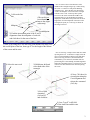
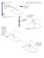
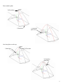
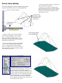
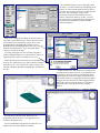
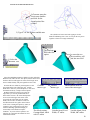
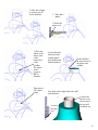
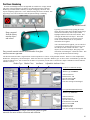
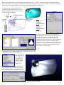
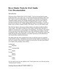
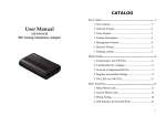
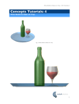
3) Move the cursor along
the X direction (be
careful to stay on the X
axis alignment so that the
line is perpendicular) and
click for the second point
of the line. Type 0.5” for
the length and hit enter.
1) Select the line tool
2) Use the Drafting Assistant to locate
the midpoint and click here for the first
point of the line.
Make another 0.5”
perpendicular line on
the other side.
3) Snap to the endpoint of the line
for the second point of the spline
1) Select the through point
spline tool
2) Start the spline here
4) Finish the spline
here. To complete the
spline, double click the
last point or select the
spline tool again.
Make another spline on the other side
of the rectangle
2
1) Select the line
tool
(*Be careful not
to accidentally
snap to the origin
at this step)
Now we want to draw a line that starts in the
middle of the rectangle and goes up 3 inches along
the Z axis. To do this we will put the Drafting
Assistant to use. Select the line tool, then briefly
“touch” the midpoint of two sides of the rectangle
with the cursor. This “wakes up” those points.
Now move the cursor towards the middle of the
rectangle and try to get the Drafting Assistant to
display the virtual intersection point of the X and Y
alignments off of the midpoints of the sides of the
rectangle (the point you “woke up”) as shown in
the image to the left.
Midpoint
Midpoint
2) Find the intersection point of the X and Y
alignments from the midpoints of each side
and click there for the start of the line.
3) Now go up along the Z axis and click some distance up along Z for
the second point of the line, then type 3” for the length at the bottom
of the screen and hit enter.
1) Select the move tool
2) Hold down shift and
select both sides of the
rectangle
Now we will copy a couple of lines and move them
up along the Z axis. To do this we simply select the
move tool, then hold down shift to select both lines
that we will copy and move, then hold down the
command key (Ctrl on the PC) and then click two
points along the Z axis Drafting Assistant alignment.
When the Command (Ctrl) key is released we are left
with two new lines that have been moved up along
the Z axis.
4) Next, Click here for
second point along the
Z axis alignment and
release the command
(Ctrl) key
3) First, Hold
command
(Ctrl on PC)
and click here
5) Last, Type 2” in dZ field
of the status line and hit enter
3
1) Select the line tool
2) Draw a .5” line
from the midpoint,
along the Y axis as
shown
Now lets make some more splines off of our
construction lines.
Now we will finish creating construction lines and
finish the defining wireframe geometry of the headlight
reflector.
3) Draw a second
.5” line on the
other side too.
3) Go to the endpoint
of the small line for
the second point
1) Select the
through-point
spline tool
4) Finish the
spline here at
this end point.
Double click
this last point
or select the
spline tool
again to end
the spline.
2) Start the spline here
at this end point
Draw another
spline on the
other side just
like the first
4
Draw another spline
2) Go to here
1) Start here
3) Finish the
spline here
One last spline over the top
1) Start here
2) Go to here
3) Finish the
spline here
5
Part Two: Surface Modeling
Now that the wireframe geometry is complete we
can start creating the first surface.
First select and delete all of the construction geometry
to get it out of the way since we no longer need it.
Select the “Cover” Surface tool and then hold
down shift and select the four curves that define the
bottom of the shape as shown at the left. Release
the shift key and a flat surface should be created
within those four curves.
Now let’s create a surface
2) Select these
four lines as the
boundaries for
the surface
1) Select the cover
surface tool
*NOTE: If a surface does not seem to appear, it
may be because the display is set to wireframe
mode. To change the display mode, go to the
render menu and select “render options”. Set all
three options to a shaded mode such as gouraud or
phong from the pull down lists.
A flat surface should
be created like this
*You can also change your object colors, like the
surface if it seems too dark using the default black
color or to help differentiate between multiple
objects. To change an object’s color, just select the
object and then select color from the pen menu and
choose what color you want.
The surface may be set to a low resolution by
default and so may appear jagged. To fix this, select
the surface, then go to the edit menu and select
“change resolution”. Increase the resolution to either
very fine or super fine and also turn on some UV Iso
lines just so that it is easier to distinguish individual
surfaces and how they are oriented. This becomes
more useful as models become more complicated.
This is completely optional of course, and you can set
these settings any way you like.
6
The resolution settings we just set only apply to that
one surface. In order to make those settings apply to all
surfaces we create from this point forward, we have to
go and set those up in the preferences located under the
file menu. Select the display category in the
preferences and increase the resolution for curves,
surfaces, and solids to whatever you like. You may
also want to take a moment and browse through all of
the preferences and familiarize yourself with the
various settings here.
While we are setting up some things to make life easier, we
can assign a couple short-cut keys. Select “short-cuts” from
the file menu then scroll down the category list to “view”.
Scroll through the commands until you find “tri-view”.
Highlight tri-view, then highlight the “shortcut key” box just
under the command window. Type “t” and then hit the
“assign key” button to the right.
A message will appear (if a letter is already assigned to
another command) asking you to confirm that you want to reassign the letter t to this new command, so say “yes”.
Follow the same process for the side view and program it to
be the “s” key. Make the top view “d” (for down), and make
the front view “f”. Now switch to the “render” category and
select the command “Wireframe/GouraudEdges” and make its
key “w”.
Vellum Solids also has some shortcut for zooming in and
out rather than selecting a zoom tool. If you hold down the
command key (shift+ctrl on the PC) then drag diagonally
from the upper left to the lower right as shown, the screen
will zoom in on that area. Dragging from the lower right to
the upper left will zoom previous, while dragging from the
upper right to the lower left will zoom out. You should
practice this since it will quickly become a valuable
shortcut.
You can also try out some of the shortcut keys we
programmed such as the “w” key for toggling between
wireframe and shaded views.
For more information on preferences and short cuts, you
should refer to the Vellum Solids user manual.
7
Create a second
cover surface on
the side
Select these two curves as
the boundaries for this
surface.
Make the
same surface
on the other
side too
M2
M3
Now we will create the final surface of the base
shape. For this surface we will use the “net”
surface tool. Before we begin though, use the
Show/Hide palette to hide the other surfaces so that
they are not in the way. Select Hide on the
Show/Hide palette then select each surface and it
will disappear.
N3
N1
N2
M1
Select the Net Surface tool
A net surface is defined by a set of curves that are oriented
in two different directions such that they form a grid or “net”.
Select the net surface tool. The message line at the top of the
screen will first ask you to choose the “M” curves. This
means it wants you to select a set of curves oriented all in
approximately the same way. So hold the shift key down and
select curves M1, M2, and M3 (see image above). Release the
shift key and the message line will now read “select N
curves”. It is asking you to now select a group of curves
oriented perpendicular (approximately) to the M curves. So
hold shift again and select curves N1, N2, and N3 (see image
above). As soon as you release the shift key this time, a
surface should appear like the one shown at the right.
Congratulations, you have created your first complex surface.
Viola, a net
surface!
8
Part Three: Solid Modeling
Now we have created all four surfaces that create a closed
volume forming our basic shape. Hit the “show all” option on
the “show/hide” palette to display any surfaces that are
hidden. Now we can create a single solid from those surfaces
and begin editing the shape.
Surfaces
Solid
Select the “stitch surfaces into solid” tool, then drag a
selection box around all of the surfaces to select them. A solid
object should be created.
Now we will make a cylinder and add it to the base shape.
First though, we need to create another construction line to
reference the cylinder off of.
1) Select the line tool
2) Start the line at
this intersection
point at the top of
the dome
3) Go up along the Z
axis some distance and
click the second point
4) Type .5” for the length and hit enter
Now select the Solid Cylinder tool from the solid primitives
palette. Choose the two point creation method from the three
options at the upper left corner of the screen. Start the cylinder
at the top endpoint of the line, then go down along the Z axis
some distance and click for the second point. A cylinder should
be created. Type 1” for the diameter at the bottom of the screen
and hit enter. *NOTE: It doesn’t matter how far down the Z
axis you go for the second point just as long as the cylinder’s
bottom face is completely inside the base part (see picture).
Hit the “w” key to switch to a wireframe view to make it
easier to see the geometry we want to snap to. Now select the
line tool and draw a .5” line from the top of the dome shape
up along the Z axis.
2) Make sure the
two point creation
method is selected
3) Start the cylinder at
the endpoint of the line
1) Select the
cylinder tool
9
4) Go down along the
Z axis some distance
and click for the
second point of the
cylinder
5) Type 1” for the diameter and hit enter
The cylinder will resize itself after typing 1” for the
diameter and hitting enter. Now we can join the two pieces
together to form a new single solid shape.
The Boolean add
tool is the first
option
2) Select the two
pieces and they will
join into one solid
1) Select the
“Boolean” tool
Select the Add/Subtract/Intersect Solid tool (often called the
Boolean tool), make sure the first option (add) is chosen from
the three choices at the upper left corner, then simply select
the two solids and they will join together into one solid.
Now that the two solids are joined together we can
Constant
put a blend at the seem where they join. Vellum
Blend Type
Solids has a wide array of blend options, so lets select
the blend tool and try a couple of those options.
With the blend tool selected, just select the
edge where you want to put the blend and a
blend will be created. All of the blend options
are accessed at the upper left corner of the
screen like all of the other tools in Vellum
Solids, and of course, all numeric values for
the radius and such are typed in at the bottom
of the screen. Hitting the option key (Mac) or
control key (PC) will bring up a few more
advanced blending options for helping to
successfully create blends in complex
The default setting:
situations. Try some of these options to see
Constant blend, radial
what they do, and check the manual for more
with .5” radius
information on them.
Variable
Blend Type
Blend options menu for
each of the blend types
Variable blend, Fixed
Width, .5” radius
Variable blend, Fixed
Width, 1.0” radius.
10
(*At this point I selected “show-only” on the show/hide palette and selected the solid object. This hides all of the wireframe geometry so
that it won’t get in the way.)
Now put blends on the edges of the sides of the part to
smooth out the shape. You can put any size and type of
blend that you want to. The image to the left shows a
Variable blend with the constant width option and a radius
of .5”.
Put a blend on
this edge
Rotate the view
around and put a
blend on the
back edge too
The image to the right shows a Constant radial blend with a
radius of .5” applied to the edge on the other side of the part
(the view has been rotated around with the trackball to show
the opposite side).
The overall shape is almost finished. Now we just need to hollow out the shape and it will start to look like a headlight reflector.
Select the front face to be
left open. An ambiguity
box comes up when there
is more than one face
where you clicked
allowing you to choose the
correct face.
3) Select the face to be
left open
1) Select the
Shell Tool
2) Type .0625” for
the wall thickness
After a few moments the
part will be hollowed out
11
The last step for the headlight reflector is to put a hole at
the top for the light bulb. This is as easy as selecting the
hole tool and then selecting where to put the hole.
2) Select
simple
hole
3) Select
through
hole
4) Select normal
hole
1) Select the
Hole Tool
After selecting the hole tool, you must also select
the type of hole you want from the options at the
top of the screen. In this case we want to select the
“simple”, “through”, and “normal” hole options.
5) Type the hole
diameter of .5” at the
bottom then select the
face to put the hole
through. Once again,
the ambiguity box
comes up when there is
more than one possible
face to select.
6) After selecting the
face to put the hole
through, then select the
exact location to put the
hole. Use the drafting
assistant to locate the
center point of the top
face and select it.
A hole is
created
Now the reflector shape is finished so we will quickly add a second part (a simple light bulb) to show how you can make assemblies in
Solids and use the Drafting Assistant to reference existing geometry. In Vellum Solids there is no separate “assembly mode” like in many
other programs.
2) Find the center
point of the circle
1) Select the
Cylinder tool
3) Go up along Z a bit
and click for the first
point of the cylinder
4) Go down along Z a
ways and click for the
second point of the
cylinder
You don’t have to always specify exact dimensions for
the size and placement of objects. You can just go with
what looks right and then you can always change things if
you want at a later time in Vellum Solids.
12
5) After the cylinder
is created, type .5”
for the diameter.
Now add a
sphere
1) Select the
sphere tool
2) Place the
sphere at the
center point
of the
bottom face
of the
cylinder.
The sphere
in the
picture is
.85” in
diameter.
This shows a
.75” radius
blend.
Use the Boolean
add tool to first
join the sphere
and cylinder and
then blend them
Put the blend at
the intersection of
the sphere and
cylinder
Now shell out the light bulb with a .01”
wall thickness
1) Select
the shell
tool
2) Select the
top face to be
removed and
the part will
be shelled out.
13
Part Four: Rendering
Now that our headlight reflector and light bulb are modeled we can play around
with some of the presentation type features of Vellum Solids such as rendering.
Rendering in Vellum Solids is basically as simple as dragging “materials” onto
objects and placing lights in the “scene” and then hitting the render command. This
page will go over some of the basic tools and options relating to rendering.
The finished model
Typically you will start out by opening the render
library from the render menu, and then simply drag a
material from the library onto an object until it
highlights and then release the mouse button. This
will apply the material to the object. The model
won’t visibly change but you can select preview
render from the render menu to verify that the
material has been applied.
Drag a material
from the library
onto the object
and release.
After a material has been applied, you can edit all of
it’s properties by opening the edit object box (open
the edit objects box from the edit menu > “edit
objects”) for the selected object, then going to the
material tab, then hitting the “advanced” button. This
brings up the advanced material settings.
Drag a metal material onto the reflector and a clear glass
material onto the light bulb.
The advanced material editor is organized into 5 main components or “classes” of the particular material. Those are Color, Displacement,
Reflectance, Transparency, and TextureSpace. Each Class has a list of possible “Shader Types” to choose from. Each Shader Type then has
a group of attributes for it, each of which can be edited. Any material you can create is made from a unique combination of these attributes
from the 5 Classes.
Shader Type Shader Class
Attributes
Adjustable Attribute Value
The Reflector Material Settings:
-Shader Class: Reflectance
-Shader Type: Conductor
Ambient Factor: 0
Diffuse Factor: 1.0
Specular Factor: 0.50
Mirror Factor: 0.85
*All other settings left unchanged
The Light Bulb Material Settings:
-Shader Class: Reflectance
-Shader Type: Dielectric
*Make sure to turn on the double sided facets option for glass
materials for more realistic reflections and refraction.
Ambient Factor: 0
Diffuse Factor: 0
Specular Factor: 5.0
Transmission Factor: 0.90
Mirror Factor: 0.90
Roughness: 0.10
Refraction: 1.60
*All other settings left unchanged
14
After you have applied materials you should place some lights in the “scene”. Do this by turning on the light palette from the rendering
menu, then selecting one of the light types (distant, spot, or bulb) and clicking where you want to place a light. After you have placed lights
in the scene you can edit their properties by selecting one of them and opening the edit objects box.
For this light setup, a light is placed inside the
light bulb, a second is placed just outside of the
light bulb, and a third light is placed out side and
behind to the left of the reflector.
3
Bulb type lights
The light
palette
Shaded View
with lights
1
2
Light 1
Intensity- .40
AttenuationUnclamped Linear
Light 2
Intensity- 1.25
AttenuationUnclamped Linear
Light 3
No Changes
The edit object box shown above is for the light that is
inside the light bulb. Two settings have been changed from
the default. Intensity has been changed to .40 and the
Attenuation has been set to Unclamped Linear. The
Attenuation settings are basically more realistic calculations
of how light becomes less intense the further from the
source it gets. The second light, the one just in front of the
light bulb, is also set to Unclamped Linear Attenuation and
it’s intensity is set at 1.25. The third light, the one in the
back, is left on all default settings.
The last step is to change the background color by choosing “edit background”
from the Render menu. The background is set to “graduated” with the top color
as Midnight blue and the bottom color Black.
Once everything has
been set up, you can
see how it looks by
choosing the full
“Raytrace Render
(shadows on, antialias)” from the
render menu.
To make a final rendering, choose “Render to File”.
In the dialog box choose the render mode, the file
format, and the resolution (width and height) then hit
save. Open that image in any graphics program.
The final rendered image
15
16