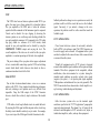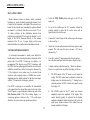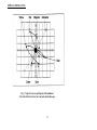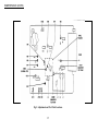
1
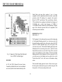
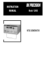
INSTRUCTION
MANUAL
Model 1249B
NTSC GENERATOR
TEST INSTRUMENT SAFETY
WARNING
Normal use of test equipment exposes you to a certain amount of danger from electrical shock because testing must sometimes be performed
where exposed voltage is present. An electrical shock causing 10 milliamps of current to pass through the heart will stop most human
heartbeats. Voltage as low as 35 volts dc or ac rms should be considered dangerous and hazardous since it can produce a lethal current under
certain conditions. Higher voltages pose an even greater threat because such voltage can more easily produce a lethal current. Your normal
work habits should include all accepted practices to prevent contact with exposed high voltage, and to steer current away from your heart in
case of accidental contact with a high voltage. You will significantly reduce the risk factor if you know and observe the following safety
precautions:
1. Connect the NTSC Generator’s ac power cord only to a 3-wire outlet to assure that the instrument’s chassis and ground leads or probes
ore test cables are at earth ground.
2. Don't expose high voltage needlessly to the equipment under test. Remove housings and covers only when necessary. Turn off equipment
while making test connections in high-voltage circuits. Discharge high-voltage capacitors after removing power.
3. If possible, familiarize yourself with the equipment being tested and the location of its high voltage points. However, remember that high
voltage may appear at unexpected points in defective equipment.
4. Use an insulated floor material or a large, insulated floor mat to stand on, and an insulated work surface on which to place equipment;
and make certain such surfaces are not damp or wet.
5. Use the time proven "one hand in the pocket" technique while handling an instrument probe. Be particularly careful to avoid contacting a
nearby metal object that could provide a good ground return path.
6. When testing video equipment that includes a picture tube or CRT, remember that the high voltage power supply and CRT anode operate
at very high voltage, often 20,000 volts or more. Carefully void these areas when the equipment is operating. It is also typical for these
circuits to retain a high voltage charge long after the equipment is turned off. Before attempting any servicing with the power removed,
discharge high voltage pints. Also avoid bumping the CRT with a sharp edge. Because of the high vacuum, a nicked CRT may “implode”
and cause flying glass fragments.
(continued on inside rear cover)
2
TABLE OF CONTENTS
Page
Page
Black Raster Pattern .......................................................... 25
4.5MHz Subcarrier Use ........................................................... 25
RGB Output ............................................................................. 25
Waveform Monitoring ............................................................. 26
Simultaneous Outputs .............................................................. 27
TEST INSTRUMENT SAFETY ............................. inside front cover
INTRODUCTION ........................................................................4
FEATURES .......................................................................................... 5
SPECIFICATIONS .............................................................................. 6
APPLICATIONS .............................................................................. 28
NTSC Color Bars ..................................................................... 28
Staircase ................................................................................... 29
Convergence ............................................................................. 29
RF and I-F ................................................................................ 29
Sync .......................................................................................... 30
30Hz Output ............................................................................. 30
CCTV Applications ................................................................. 30
CATV Applications ................................................................. 30
MATV Applications ................................................................ 31
Vectorscope Measurements .................................................... 31
DEFINITIONS OF TERMS ................................................................ 8
THE NTSC COLOR VIDEO SIGNAL ............................................ 11
History ......................................................................................... 11
Horizontal Sync ........................................................................... 11
Vertical Sync ............................................................................... 12
Amplitude .................................................................................... 12
Color ............................................................................................ 15
NTSC Color Bars Signal ............................................................. 15
CONTROLS AND INDICATORS ................................................... 18
MAINTENANCE ..................................................................... 34
Case Removal ......................................................................... 34
Fuse Replacement ................................................................... 34
Calibration ....................................................................... 34
OPERATING INSTRUCTIONS ....................................................... 22
Precautions and Tips ................................................................... 22
Familiarization ............................................................................ 22
Initial Set-Up ............................................................................... 22
NTSC Standard Color Bar Pattern ............................................. 24
Staircase Pattern .......................................................................... 25
Color Bars With 100% White ..................................................... 25
Staircase With 100% White ........................................................ 25
Convergence Patterns .................................................................. 25
SERVICE INSTRUCTIONS ...................................................... 38
LIMITED ONE- YEAR WARRANTY ....................................... 39
3
INTRODUCTION
it to be used to set-up and adjustment TV sets and other
equipment for the best performance. This is not possible
with lower cost gated rainbow color generators, which
produce a signal unlike that used during normal operation.
The B+K PRECISION Model 1249B NTSC Generator is a
versatile, low cost, precision television/video signal
generator. It generates a variety of test signals and patterns for
comprehensive testing, servicing, and adjustment of video and
television equipment. Its applications include television
receivers, video tape recorders, closed circuit television
systems and components, and master antenna systems and
components, as well as most standard computer and video
monitors.
Separate RGB and sync outputs are available for use with
most computer and video monitors using standard 525 line.
15.750KHz scan. The inputs to these RGB monitors are
separate digital signals for red, green, and blue, and separate
digital composite sync or separate digital vertical and
horizontal sync. The signal level at the RGB outputs is switch
selectable between TTL and low (0.8V). The D-type
subminiature connector is directly comparable with IBM
Model 5153 PC monitors (TTL signal level should be
selected for use with the IBM PC monitor).
Other features include a crystal generated 30Hz TTL output
and a switchable 4.5MHz sound sub-carver modulated with
a 1 kHz audio tone. The 30Hz signal is useful for isolating
servo problems in video cassette recorders.
The instrument can generate many different patterns, each of
which is available as a composite video signal or a modulated
rf output on channel 3, channel d, or the standard television i-f
frequency of 45.75MHz. This provides the proper signal for
injection at any point in the equipment.
The video patterns include standard NTSC color bats with
standard 75% white or with 100% white, staircase, black raster,
and an assortment of convergence patterns. An engineer or
technician with a good knowledge of video circuits can use the
variety of patterns to analyze and isolate almost any video
problem.
The switch selectable 4.5MHz sound sub-carrier is
modulated by a 1KHz tone and is used to check the sound
circuits and audio/video isolation.
The NTSC Color Bars signal generated by the instrument is
the same type of color bar signal that is used by the television
networks, allowing
4
FEATURES
RF OUTPUT
Standard 75Ω output modulated by composite video at
10mV rms on channel 3, channel 4, or 45.75MHz i-f.
NTSC COLOR BARS
Generates standard NTSC color bars pattern (eight bars of
standard EIA colors) at NTSC prescribed luminance and
chrominance levels and phase.
SYNC PULSE OUTPUTS
All outputs can be used simultaneously for maximum
flexibility. Permits more complementary testing or
multiple independent usage of instrument.
SELECTABLE COLOR
Color can be switched on or off.
RGB OUTPUTS
CONVERGENCE PATTERNS
Digital red, green and blue (RGB) signals for computer and
video monitors with standard 525 line, 15.750KHz scan. DType sub-miniature connector provides red, green, blue,
horizontal sync, and vertical sync signals and is IBM Model
5153 PC monitor compatible. Output level is switch
selectable between TTL and LOW ( 0 . 8 ± 0 . 2 V ) .
Dots, crosshatch, center dot, and center cross patterns for
static and dynamic convergence.
BLACK RASTER
Provides sync and reference black for a clear blemish-free
raster.
30Hz OUTPUT
CRYSTAL OSCILLATORS
30Hz TTL output is useful for video recorder applications.
IF, CH 3, CH 4. 30Hz. and sync generation are crystalcontrolled for frequency accuracy and stability.
4.5MHz SOUND SUB-CARRIER
4.5MHz subcarrier modulated with 1KHz audio tone can be
switched on to check sound and verify picture and sound
isolation.
COMPOSITE VIDEO OUTPUT
Composite video output with variable 0 to ± 1V p-p amplitude
into standard 75Ω impedance. Calibrated 1V p-p with
negative sync.
5
SPECIFICATIONS
PATTERNS
Impedance:
75 ohms.
NTSC Color Bars:
White (75% or I00%. switch selectable), yellow, cyan,
green, magenta, red, blue, black (7.5% set-up). Chroma is
switch selectable; COLOR OFF obtains stair case from
color bars (stair case white level is switch selectable at 75%
or 100%). Interlaced scan.
Chroma Accuracy
Stability:
50 ppm.
VIDEO OUTPUT
Polarity :
Negative and positive sync available.
:
±5° and ±5 EEE units.
Amplitude:
Raster:
Variable 0 to ±1V p-p into 75 ohms. Calibrated 1V p-p
available with negative sync.
Black.
Convergence:
Impedance:
Center dot, 7 x 11 dots, center cross,7 x 11 crosshatch.
Selectable interlaced or progressive scan.
75 ohms.
RGB OUTPUTS
RF OUTPUT
BNC and D-Type Sub-Miniature Connectors.
Channels:
Patterns:
CH3, CH4, IF.
Convergence and color bars.
Frequency:
Levels:
TTL level and low level, (0.8±0.2V), switch
61.25, 67.25, 45.75MHz ±0.008MHz.
Level:
selectable.
10mV rms minimum into 75 ohms.
Impedance:
75 ohms.
6
SPECIFICATIONS (CONT.)
COLOR SUBCARRIER
NTSC signal: 3.579545MHz (±50Hz) (adaptable to PAL-M).
SOUND SUBCARRIER
4.5MHz ±0.2% modulated by approximately 1KHz
audio tone, switch selectable.
MISCELLANEOUS
Power Requirements:
105 to 130VAC, 60Hz. 8 Watts.
Operating Temperature:
SYNC OUTPUTS
Composite:
NTSC-M TTL level: negative polarity sync:
interlaced scan for NTSC color bars, selectable
interlaced or 'progressive scan for convergence
patterns.
Horizontal:
TTL level (positive polarity sync).
0° to +50°C.
Dimensions (H x W x D):
3-3/8" x 10-3/8" x 11-7/16" (8.6 cm x 26.4 cm x 29.1 cm)
Weight:
2.8 lbs (1.30 kg).
Vertical:
TTL level (positive polarity sync).
OPTIONAL ACCESSORIES
Impedance:
BNC-to-F Five Foot RG-59/U Cable
(part number 539-124-0-000).
BNC-to-BNC Five Foot RG-59/U Cable
(part number 539-123-0-000).
75 ohms.
30 Hz OUTPUT
Level:
TTL level square wave.
Impedance:
75 ohms.
NOTE: Specifications and information are subject to change without notice. Please visit www.bkprecision.com for the most current product
information.
7
DEFINITIONS OF TERMS
Color Burst. A few (8 to 10) cycles of 3.58MHz color subcarrier
which occur during the back porch interval. Color burst amplitude is
40 IEEE units and phase is 180°. The color oscillator of a color
television receiver is phase locked to the color burst.
BARS Pattern. See “NTSC Color Bars”.
Back Porch. The portion of a composite video signal between
the trailing edge of the horizontal sync pulse and the end of the
horizontal blanking pedestal. The color burst occurs during the
back porch interval.
Color Subcarrier. The 3.58MHz signal which carves color
information. This signal is superimposed on the luminance level.
Amplitude of the color subcarrier represents saturation and phase
angle represents hue.
Blanking Level. The level of the front and back porches. Zero
IEEE units.
Composite Video Signal. The entire video signal consisting of
blanking pulses, sync pulses, color burst, and chrominance and
luminance information.
Burst. See "Color Burst".
CATV Cable Television. Also used for Community Antenna
Television.
Duty Cycle. Percentage of cycle during which pulse is working.
A square wave has a 50% duty cycle. Horizontal sync pulses have
about 8% duty cycle-about 5µs pulse width at 63.5µs pulse
repetition period.
CCTV. Closed-circuit television.
Chroma or Chrominance. The color information contained in
a video signal, consisting of hue (phase angle) and saturation
(amplitude) of the color subcamer.
EIA. Electronic Industries Association.
Equalizing Pulse. A portion of the vertical blanking interval
which is made up of blanking level and six pulses (8% duty cycle
at -40 IEEE units) at one-half the width of horizontal sync pulses
and at twice the repetition rate. One equalizing pulse occurs
immediately before, and another immediately after, the vertical
sync pulse.
Chroma Amplitude. . Amplitude of 3.58MHz color subcarrier.
Represents saturation.
Chroma Phase Angle. Phase angle of 3.58MHz color
subcarrier. Represents hue.
Color Bars. See "NTSC Color Bars".
8
DEFINITIONS OF TERMS (CONT.)
Frame. A complete television picture, consisting of two fields.
See "Field".
IEEE Unit. A standard 1-volt peak-to-peak composite video signal
is divided into 140 equal units, scaled from -40 to +100, which are
then called IEEE units. Luminance and chrominance amplitude are
measured in IEEE units. Sync pulses extend from 0 to -40 units.
Blanking level is 0. Picture information spans the +7.5 set-up level
(black) to + 100 (100% white) levels. Chroma amplitude is the peakto-peak amplitude of the color subcarrier, which rides on the
luminance level.
Front Porch. Blanking level pulse at end of line of horizontal
scan, before horizontal sync pulse.
Interlace. Vertical offset between Field 1 and Field 2 that causes
lines of Field 1 to fall between the lines of Field 2. Also see "Field".
Horizontal Blanking Pedestal. That portion of each line of
composite video signal which blanks the picture while the CRT
retrace returns to the left side of the screen. Consists of front
porch, horizontal sync pulse, and back porch.
Luminance. The amount of light intensity perceived by the eye as
brightness. Luminance information is represented by the amplitude
of the composite video signal.
Field. One-half a television picture. One complete vertical scan
of the picture containing 262.5 lines. Two fields make up a
complete television picture (frame). The lines of Field 1 are
vertically interlaced with Field 2 for 525 lines of resolution.
MATV. Master antenna television.
Horizontal Resolution. Smallest increment of a television
picture that can be discerned in the horizontal plane. This
increment is dependent upon the video bandwidth and is
measured in frequency. Horizontal resolution of a high quality
monochrome television receiver is 4.2MHz.
Monochrome. Black and white television signal. Contains sync
and luminance but no color burst or chroma.
NTSC. National Television Systems Committee. Established the
color television standards now in use in the U.S.A., and many other
nations of the world.
Horizontal Sync Pulse. Pulse at -40 IEEE units which
synchronizes horizontal scan rate of television receiver to
composite video signal. Starts each line at same horizontal
position.
NTSC Color Bars. A pattern generated by the NTSC Generator,
consisting of eight equal width color bars. Colors are white (75%),
black (7.5% set-up level), 75% saturated pure colors red, green, and
blue, and 75% saturated hues of yellow, cyan, and magenta (mixtures
or two colors in 1:1 ratio without third color).
Hue. Distinction between colors. Red, blue, green, yellow, etc.
are hues. White, black, and grey are not considered hues.
I FFE. Institute of Electrical and Electronic Engineers.
9
DEFINITIONS OF TERMS (CONT.)
Resolution. See "Horizontal Resolution" and "Vertical
Resolution".
Vertical Blanking Interval. That portion at the beginning
of each field of composite video signal which blanks the
picture while the CRT retrace returns to the top of the
screen. The equalizing pulses and vertical sync pulse are
generated within this interval.
Saturation. Vividness of color. Degree to which a color is
not diluted by white light. Highly saturated color is very
vivid. The same hue becomes a pastel shade when diluted
by white light. Saturation is represented by chroma
amplitude and is measured in IEEE units. The number of
IEEE units for fully saturated color vanes from hue to hue.
Vertical Resolution. Smallest increment of a television
picture that can be discerned in the vertical plane. This
increment is dependent upon the number of lines of scan per
frame, and is measured in lines. In the U.S.A. and other
countries using NTSC systems, vertical resolution is 525
lines.
Set-up. The separation between blanking and black
reference levels. This instrument uses the NTSC standard
set-up level of 7.5 units.
Vertical Sync Pulse. A portion of the vertical blanking
interval which is made up of blanking level and six pulses
(92% duty cycle at -40 [FEE units) at twice the horizontal
sync pulse repetition rate. Synchronizes vertical scan of
television receiver to composite video signal. Starts each
frame at same vertical position (sequential fields are
offset line to achieve interlaced scan).
Staircase. A pattern generated by the NTSC Generator.
consisting of equal width luminance steps decreasing in
amplitude. The staircase pattern is useful for checking
linearity of luminance.
Subcarrier. See “Color Subcarrier”.
VCR. Video cassette recorder.
VTR. Video tape recorder. In this manual. the term "VTR"
includes reel-to-reel and cassette type.
10
THE NTSC COLOR VIDEO SIGNAL
United States and many other countries. It was, of course,
compatible with the monochrome (black and white) system that
previously existed. The makeup of a composite video signal is
dictated by NTSC specifications. These specifications include a
525-line interlaced scan, operating at a horizontal scan frequency of
15.734.26Hz and a vertical scan frequency of 59.94Hz. A
3.579545MHz subcarrier contains the color information. The phase
angle of the subcarrier represents the hue: the amplitude of the
subcarrier represents saturation.
HORIZONTAL SYNC
(Refer to Fig. 1)
HISTORY
The "beginning" of a line horizontal scan occurs at the leading edge
of the horizontal blanking pedestal. In a television receiver, the
horizontal blanking pedestal starts as the electron beam of the CRT
reaches the extreme right-hand edge of the screen (plus a little
overscan in most cases). The horizontal blanking pedestal prevents
illumination of the screen during retrace, that is, until the electron
beam deflection circuits are reset to the left edge of the screen and
ready to start another line of video display. The entire horizontal
blanking pedestal is at the blanking level or the sync pulse level. In
a television receiver, the blanking and sync pulse levels are the
"blacker than black" levels that assure no illumination during
retrace.
In 1953, the NTSC (National Television Systems
Committee) established the color television standards
now in use by the television broadcast industry in the
The horizontal blanking pedestal consists of three discrete parts:
the front porch, the horizontal sync pulse, and the back porch. The
front porch is a 1.40 microsecond period at second
Fig. 1. Composite of Video Signal; One Horizontal
Line of NTSC Color Bars Signal
11
THE NTSC COLOR VIDEO SIGNAL (CONT.)
horizontal sync pulse at the -40 IEEE units level. An explanation
of IEEE units follows in the "Amplitude" paragraph. When the
horizontal sync pulse is detected in a television receiver, it
initiates flyback, which ends the horizontal scan and rapidly
resets the horizontal deflection circuit for the next line of
horizontal scan. The horizontal sync pulse is followed by a 4.79
microsecond back porch at the blanking level. When a color
signal is being generated, 8 to 10 cycles of 3.579545MHz color
burst occur during the back porch. The color burst signal is at a
specific reference phase. In a color television receiver, the color
oscillator is phase locked to the color burst reference phase before
starting each horizontal line of video display. When a
monochrome signal is being generated, there is no color burst
during the back porch.
interval begins with the first equalizing pulse, which consists of
six pulses one half the width of horizontal sync pulses, but at
twice the repetition rate. The equalizing pulse has an 8% duty
cycle. The vertical sync pulse occurs immediately after the fast
equalizing pulse. The vertical sync pulse is an inverted
equalizing pulse at 92% duty cycle. The wide portion of the
pulse is at the -40 IEEE units level and the narrow portion of the
pulse at the blanking level. A second equalizing pulse at 8%
duty cycle occurs after the vertical sync pulse, which is then
followed by 13 lines of blanking level (no video) and
horizontal sync pulses to assure adequate vertical retrace time
before resuming video scan. The color burst signal is present
after the second equalizing pulse.
Note that in Field 1, line 522 includes a full line of video,
while in Field 2 line 260 contains only a half line of video. This
timing relationship produces the interlace of Fields l and 2. The
NTSC color bars pattern generated by this instrument is
interlaced per NTSC standards.
VERTICAL SYNC (Refer to Fig. 2)
A complete video image as seen on a TV screen is called a
frame. A frame consists of two interlaced vertical fields of 262.5
lines each. The image is scanned twice at a 60Hz rate (59.94Hz to
be more precise), and the lines of Field 2 are offset to fall
between the lines of Field 1 (interlaced) to create a frame of 525
lines at a 30Hz repetition rate.
AMPLITUDE (Refer to Fig. 1)
A standard NTSC composite video signal is 1 volt peak-topeak, from the tip of a sync pulse to 100% white. This 1 volt
peak-to-peak signal is divided into 140 equal parts called IEEE
units. The zero reference level for this signal is the blanking
level. The tips of the sync pulses are at -40 units and a sync
pulse is approximately 0.3 volt peak-to-peak. The portion of
the signal that contains video information is raised to a set-up
level of +7.5 units above the blanking level. A monochrome
video signal at +7.5 units is at the black threshold. At +100 units
the signal represents 100%
At the beginning of each vertical field, a period equal to several
horizontal lines is used for the vertical blanking interval. In a
television receiver, the vertical blanking interval prevents
illumination of the CRT during the vertical retrace. The vertical
sync pulse, which is within the vertical blanking interval, initiates
reset of the vertical deflection circuit so the electron beam will
return to the top of the screen before video scan resumes. The
vertical blanking
12
THE NTSC COLOR VIDEO SIGNAL (CONT.)
Fig. 2A. Compo site Video Signal Showing Vertical Blanking Interval (Field 1).
13
THE NTSC COLOR VIDEO SIGNAL (CONT.)
Fig. 2B. Composite Video Signal Showing Vertical Blanking Interval (Field 2)
14
THE NTSC COLOR VIDEO SIGNAL (CONT.)
Hue is the element that distinguishes between colors, red, blue,
green. etc. White, black and grey are not hues. The phase angle of
the 3.58MHz color subcarrier determines the hue. The three
primary video colors of red, blue, and green can be combined in
such a manner to create any hue. A phase shift of 360° will produce
every hue in the rainbow by changing the combination of red,
blue, and green.
Saturation is the vividness of a hue, which is determined by the
amount the color is diluted by white light. Saturation is often
expressed in percent: 100% saturation is a hue with no white
dilution which will produce a very vivid shade. Low saturation
percentages are highly diluted by white light and produce light
pastel shades of the same hue. Saturation information is contained
in the amplitude of the 3.58MHz color subcarrier. Because the
response of the human eye is not constant from hue to hue, the
amplitude required for 100% saturation is not the same for all
colors.
The combination of hue and saturation is known as chroma, or
chrominance. This information is normally represented by a
vector diagram. Saturation is indicated by the length of the vector
and hue is indicated by the phase angle of the vector. The entire
color signal representation is three dimensional, consisting of the
vector diagram for chrominance and a perpendicular plane to
represent the amplitude of luminance.
white. Levels between +7.5 and +100 units produce various
shadings of grey. Even when a composite video signal is not at the
1 volt peak-to-peak level, the ratio between the sync pulse and
video must be maintained. 0.3 of total for sync pulse and 0.7 of
total for 100% white.
There is also a specific relationship between the amplitude of the
composite video signal and the percentage of modulation of an rf
carrier. A television signal uses negative modulation, wherein the
sync pulses (-40 units) produce the maximum peak-to-peak
amplitude of the modulation envelope (100% modulation) and
white video (+100 units) produces the minimum amplitude of the
modulation envelope (12-1/2% modulation). This is very
advantageous because the weakest signal condition, where noise
interference can most easily cause snow, is also the white portion
of the video. There is adequate amplitude guard band so that peak
white of +100 units does not reduce the modulation envelope to
zero.
COLOR
(Refer to Fig. 3)
The color information is a composite video signal consists of
three elements: luminance, hue, and saturation.
NTSC COLOR BARS SIGNAL
Luminance, or brightness perceived by the eye, is represented by
the amplitude of the video signal. The luminance component of a
color signal is also used in monochrome receivers, which is
converted to a shade of grey. Yellow is a bright color and has a
high level of luminance (is nearer to white), while blue is a dark
color and has a low level of luminance (is nearer to black).
Refer again to Fig. 1. As mentioned previously, the chroma
amplitude required for 100% saturation of some hues is
considerably greater than for other hues. Also, the luminance level
for each color differs. The NTSC color bars signal generates
standard EIA colors at the prescribed luminance level
(brightness), chroma phase angle (hue), and chroma amplitude
15
THE NTSC COLOR VIDEO SIGNAL (CONT.)
Fig. 3. Elements of Color Television Signal
16
THE NTSC COLOR VIDEO SIGNAL (CONT.)
luminance level (or with no luminance component) and
same chroma amplitude, which of course is not equivalent
to the color signals being transmitted by broadcast stations.
Many hues are oversaturated. Also, the chroma phase angle
is normally produced by using a carrier that is offset enough
from 3.58MHz so that 360° phase shift occurs during each
horizontal line. This produces a gated rainbow pattern
rather than specific, phase controlled colors.
(saturation) set forth by the NTSC. This is the test signal
used in broadcasting studios and transmitting equipment.
This makes the NTSC Generator a superior instrument
for servicing and adjusting color television receivers and
all types of other video equipment. An NTSC color bars
pattern is specified or recommended for most tests and
adjustments in video cassette recorders.
The precision of the NTSC color bars signal is beyond
comparison with that of a low cost color bar generator. A
color bar generator usually produces all hues at the same
17
CONTROLS AND INDICATORS
1. POWER Switch. Turns power on and off.
Only LINE switch engaged:
2. RGB TTL/LOW Switch. Selects TTL or low RGB output
level. When this switch is released (LOW position), a positive
logic state at the RGB output jacks (R, G, and B BNC jacks and the
RGB 9-pin D-type connector) is at 0.8V ±0.2V level. When this
switch is engaged (TTL position), the pulses are at a TTL level.
This switch also selects interlaced or progressive scan for
convergence patterns: when the switch is released the
convergence patterns use interlaced scan, and then the switch is
engaged, the convergence patterns use progressive scan.
A single vertical and horizontal line intersecting at the center of the
screen.
LINE and 7 X 11 switches engaged:
7 horizontal lines and 11 vertical lines.
Only DOT switch engaged:
A single dot at the center of the screen.
NOTE
DOT and 7 X 11 switches engaged:
The DOT, LINE, RAST, and NTSC BARS
switches are mechanically interlocked: i.e., selection of a new pattern automatically releases the
previous selection. Releasing all four switches by
partially pressing any one of them will provide a
color bats or staircase pattern with 100% white
level. The five selectable patterns are available at
the COMPOSITE VIDEO, IR/RF, or RGB
output jacks.
3. CONVERGENCE Switches. Select one of four available
convergence patterns as follows:
7 horizontal rows by 11 vertical columns of dots.
5. RAST Switch. Selects a black or blank raster pattern. Sync and
reference black are provided for a blemish free raster.
6. NTSC BARS Switch. Selects NTSC Color Bar pattern.
7. COLOR OFF Switch. Works in conjunction with NTSC BARS switch
and selects color or monochrome (black and white) output. When this
switch is engaged, the color subcarrier is switched off and the NTSC
BARS pattern will be displayed as shades of grey. When this switch is
disengaged, the color subcarrier is switched on and the NTSC BARS
pattern will be displayed in color.
8. 4.5 MHz Switch. Turns 4.5MHz subcarrier (sound) on and off. When
this switch is engaged, a 4.5MHz sound carrier (modulated by
18
CONTROLS AND INDICATORS (CONT.)
approximately 1KHz) is included in the signal at the IF/RF
output jack. When this switch is disengaged, no sound carrier
is included in the signal.
12. COMPOSITE VIDEO Jack. Provides a video output for signal
substitution directly into the video circuits of a television receiver
and for testing video recorders.
9. IF/RF Switch. Sets modulated output signal (at the IF/RF
output jack) to rf or i-f frequency. When this switch is engaged,
the signal at the IF/RF jack is at i-f signal frequency
(45.75MHz) and the CH 4/CH 3 switch has no effect. When
disengaged, the signal at the IF/RF jack is at rf signal frequency
(61.25MHz for CH 3 or 67.25MHz for CH 4).
13. IF/RF Jack. Provides approximately 10mV rms (intoΩ)75rf
envelope modulated by composite video. Output carrier
frequency can be set to 45.75MHz (IF), 61.25MHz (CH 3) or
67.25MHz (CH 4) by the CH 4/CH 3 and IF/RF switches.
14. 30Hz Jack. Provides a 30Hz square wave TTL level output
useful for troubleshooting video recorders.
10. CH 4/CH 3 Switch. Works in conjunction with rf position of
IFIRF switch. Sets rf output carrier frequency to correspond to
CH 4 or CH 3. When the IF/RF switch is in the rf position
(disengaged) and this switch is disengaged (in the CH 3
position), the output signal at the IF/RF jack corresponds to TV
channel 3 (61.25MHz). When the IF/RF switch is in the RF
position (disengaged) and this switch is engaged (in the CH 4
position), the output signal at the IF/RF jack corresponds to TV
channel 4 (67.25MHz). When the IF/RF switch is in the IF
position (engaged), this switch has no effect on the output.
15. COMPosite SYNC Jack. Provides both horizontal and vertical
sync pulses for external use such as monitors requiring separate
composite sync or sync trigger for an oscilloscope. Sync pulse
is negative polarity. Output impedance is 75Ω, level is TTL
compatible.
16. SYNC Vs Jack. Provides vertical sync pulses for external use
such as vertical sync for RGB monitors or sync trigger for an
oscilloscope. Sync is positive polarity. Output impedance is
75Ω. Level is TTL compatible.
11. COMPOSITE VIDEO LEVEL Control. Adjusts level and
polarity of composite video signal at COMPOSITE VIDEO
output jack. Counterclockwise rotation produces a composite
video signal with negative going sync pulses (standard signal).
Full counterclockwise rotation of this control provides
maximum output signal with a calibrated level of 1Vp-p into
75Ω. Amplitude reduces to minimum at mid-point. Further
clockwise rotation reverses polarity (positive going sync) and
progressively increases amplitude. Full clockwise rotation of
this control provides an output signal with a level of
approximately 1Vp-p into 75Ω.
17. SYNC Hs Jack. Provides horizontal sync pulses for external
use such as horizontal sync for RGB monitors or sync trigger
for an oscilloscope. Sync pulse is positive polarity. Output
impedance is 75Ω. level is TTL compatible.
18. B Jack. Provides blue output signal for use with RGB monitors.
Output impedance is 75
Ω and output level is switch selectable
(using the RGB TTL/LOW switch).
19
CONTROLS AND INDICATORS (CONT.)
Fig. 4. Controls and Indicators
20
CONTROLS AND INDICATORS (CONT.)
19. G Jack. Provides green output signal for use with RGB
monitors. Output impedance isΩ75 and output level is
switch selectable (using the RGB TTL/LOW switch).
20. R Jack. Provides red output signal for use with RGB
monitors. Output impedance is 75Ω and output level is
switch selectable (using the RGB TTL/LOW switch).
21. RGB 9-Pin D-Type Sub-Miniature connector.
Provides red, green, blue, vertical sync (Vs), and
horizontal sync (Hs) signals. Pin layout and level
(TTL) are IBM Model 5153 PC monitor compatible.
Low level is also available by engaging the RGB
TTL/LOW switch.
21
OPERATING INSTRUCTIONS
3.
WARNING
To prevent electrical shock, observe the
precautions
listed
in
the
TEST
INSTRUMENT SAFETY section, located on
the inside front cover of this manual.
FAMILIARIZATION
To familiarize yourself with the operating controls, capabilities
and operating characteristics of the NTSC Generator, we
recommend that you connect it to a color television receiver
that is in proper operating condition and observe all the
patterns. An oscilloscope or waveform monitor may also be
used to observe all the waveforms produced.
PRECAUTION AND TIPS
1.
The most commonly encountered hazard in the use of this
instrument is “hot chassis” equipment. Always connect an
isolation transformer (such as the B & K Precision Model
TR-110 or 1604 Isolation Transformer or Model 1653A or
1655A AC Power Supply) between the wall outlet and any
“hot chassis” equipment under test. See the TEST
INSTRUMENT SAFETY section, steps 7 and 8 for more
information
INITIAL SET-UP
1.
2.
2.
All outputs have a source impedance of 75Ω. Therefore,
75Ω coaxial cable RG-59/U) is recommended for
interconnecting cables.
The RF/IF and COMPOSITE VIDEO outputs of this
NTSC Generator are rated to withstand voltages of -35 to
+35 volts. All other outputs are rated to withstand -5 to +5
volts. The NTSC Generator must only be connected to
circuit points where the dc + ac peak voltage is within the
specified limit (±35 volts for the RF/IF and COMPOSITE
VIDEO outputs and ±5 volts for all other outputs). If in
doubt, make a voltage measurement first. Also take care to
prevent accidental contact with high voltage points.
3.
22
Connect the power cord of the NTSC Generator to a
120VAC, 60Hz outlet
Turn on the instrument by setting the POWER switch to
the ON position (engaged). The POWER indicator will
light when the power is on.
Apply power to the equipment under test and turn it on.
For “hot chassis” equipment, use an isolation transformer.
OPERATING INSTRUCTIONS (CONT.)
4.
c.
The probe may be used to inject the 45.75MHz i-f
signal at the desired point.
d.
Patterns may now be selected.
RF Output
The rf output of the NTSC Generator may be applied to a television
receiver, video tape recorder or other video equipment tunable to
channel 3 or 4. Use the following procedure:
a.
b.
c.
Connect a coaxial cable from the IF/RF output jack of the
NTSC Generator to the antenna terminals. The 75Ω input
point is desired, or use 75Ω to 300Ω coupler.
Set the RF/IF switch on the Generator to the RF position
(disengaged).
Set the channel selector of the equipment under test to channel
3 or channel 4, whichever is not used for broadcasting in your
area.
d.
Set the CH 4/CH 3 switch on the NTSC Generator to the
same channel that was selected on the equipment under test.
e.
Patterns may now be selected.
5.
The i-f output of the NTSC Generator may be injected into the i-f
section of television receivers, video tape recorders, or any other
video product using the standard 45.75MHz i-f frequency. Use the
following procedure:
b.
Composite Video Output
A composite video signal may be applied to the input
or injected at subsequent test points of non-rf
equipment such as video monitors, video distribution
amplifiers, signal processing equipment, etc. A
composite video signal may also be injected into
circuit points after the video detector in television
receivers, video tape recorders, or other rf equipment.
The IF/RF and COMPOSITE VIDEO output jacks
may be used simultaneously if desired. Use the
following procedure:
a. Connect a coaxial cable or probe from the
COMPOSITE VIDEO jack of the Generator to
the desired point in the equipment under test.
b.
I-F Output
a.
6.
Connect a probe to the IF/RF output jack of the NTSC
Generator.
Set the RF/IF switch on the Generator to the IF position
(engaged).
23
Adjust the COMPOSITE VIDEO LEVEL
control to obtain the desired signal level and sync
polarity at the output jack. Fully counterclockwise
rotation gives maximum amplitude with negative
polarity sync. Clockwise rotation reduces level
and the center of rotation is minimum level.
Rotation past the center reverses the polarity of the
signal to positive sync and further clockwise
rotation increases signal level. Maximum
clockwise rotation is approximately 1Vp-p level,
although it is uncalibrated.
OPERATING INSTRUCTIONS (CONT.)
c.
d.
A calibrated 1Vp-p signal level with negative sync
polarity is available when the COMPOSITE VIDEO
LEVEL control is fully counterclockwise to the CAL
position.
Patterns may now be selected.
2.
Release all of the pattern selection switches (the four
black pushbuttons) by slightly depressing one of them.
Make sure that the COLOR OFF switch is disengaged.
3.
A color bars pattern with 100% white color bar on the
left side of the screen should now be displayed.
STAIRCASE WITH 100% WHITE
NTSC STANDARD COLOR BAR PATTERN
1.
Perform the "INITIAL SET-UP" procedure.
1. Perform the "INITIAL SET-UP" procedure.
2.
Press the NTSC BARS switch. Be sure that the COLOR
OFF and 4.5MHz switches are released.
2. Release all of the pattern selection switches (the four
black pushbuttons) by slightly depressing one of them.
Make sure that the COLOR OFF switch is engaged.
3.
The NTSC Color Bar pattern should now be displayed on the
screen.
STAIRCASE PATTERN
3. A monochrome bars display with progressively darker
shades of grey (left to right) should now be displayed
on the screen. The left most bar will be I00% white.
1. Perform the "INITIAL SET-UP" procedure.
CONVERGENCE PATTERNS
1. Perform the "INITIAL SET-UP" procedure.
2. Press the N T S C BARS switch and the COLOR OFF
switches.
2. Any of the four convergence patterns may be selected by
pressing the appropriate switch(es) as follows:
3. A monochrome bars (staircase) display with progressively
darker shades of grey should now be displayed (with the
lightest baron the left side of the screen and the darkest on the
right side of screen) on the screen.
COLOR BARS WITH 100% WHITE
1. Perform the "INITIAL SET-UP" procedure.
24
OPERATING INSTRUCTIONS (CONT.)
Only LINE switch engaged:
A single vertical and horizontal line intersecting at the center of
the screen.
2. Press the RAST switch. The COLOR OFF switch should
have no effect on the display regardless of whether it is
engaged or disengaged.
LINE and 7 X 11 switches engaged:
3. The screen should not be completely black (black raster or
black-burst).
7 horizontal lines and I I vertical lines.
Only DOT switch engaged:
4.5 MHz SUBCARRIER USE
A single dot at the center of the screen.
To check for audio isolation, the 4.5MHz can be switched on
when the NTSC color bars pattern is selected. In a well designed
properly adjusted receiver, the sound trap should prevent the 4.5Hz
subcarrier from affecting the picture quality. In receivers where
the audio is not completely removed from the video component
of the signal, a "herring bone" pattern will appear on the screen.
DOT and 7 X 11 switches engaged:
7 horizontal rows by I I vertical columns of dots.
3. Convergence patterns use interlaced scan when the RGB
TTL/LOW switch is released. This causes a slight jitter
effect in the appearance of the pattern. Progressive scan may
be selected by engaging the RGB TTI/LOW switch for a
jitter-free pattern. Most people prefer to use progressive
scan for convergence patterns, but some newer TV sets will
not accept the signal unless interlaced scan is used.
To check the audio circuitry, the 4.5MHz switch should be
engaged when any pattern is selected. The 4.5MHz subcarrier is
modulated by an audio tone (approximately lKHz) that can be used
to troubleshoot the audio circuitry in video equipment.
RGB OUTPUT
All convergence patterns are monochrome. On most sets the
entire 7 X 11 pattern (when 7 X 11 switch is engaged) will not be
visible due to overscan: it is desirable to display a pattern of at
least 7 horizontal and 10 vertical lines or dots.
Independent red, green, and blue (RGB) outputs are available
for testing and adjusting color monitors that use separate red,
green, and blue inputs rather than a composite video input. Such
color monitors are often used with computers having color graphic
display capability, etc.
BLACK RASTER PATTERN
1.
Perform the "INITIAL SET-UP" procedure.
25
The Model 1249B will provide compatible test signals for most
RGB monitors using standard 525 line, 15.750KHz horizontal
OPERATING INSTRUCTIONS (CONT.)
scan. It is not compatible with high resolution graphics monitors
which use special high frequency scan rates.
Some color monitors accept either composite video signals or
RGB signals. Often, positive polarity vertical and horizontal sync
is required in RGB monitors. Some RGB monitors use low level
RGB signals and vary color saturation in response to analog
changes of the signal level. Others use higher TTL level excitation
and display only fully saturated colors- The Model 1249B NTSC
Generator provides signals for most versions.
Separate R, G, and B outputs with selectable TTL or LOW
level are available at BNC connectors on the front panel. In
addition, positive polarity Vs (vertical sync) and Hs (horizontal
sync) are available at additional BNC connectors, also on the front
panel. To simplify connections, a 9-pin connector (sub-miniature
D-type) is provided which mates with the 9-pin connector used on
the most common RGB monitor configuration (the connector is
IBM PC compatible). This duplicates the functions of the R, G, B
Vs, and Hs jacks in one connector so that all connections are
made simultaneously with a single cable.
If separate vertical and horizontal positive polarity sync is
required connect the Vs and Hs outputs of the generator to
the corresponding vertical and horizontal sync inputs of the
monitor.
d.
If the color monitor is equipped with a 9-pin connector that
mates with the RGB receptacle on the Generator, connect it.
All necessary connections are made simultaneously.
2.
Select TTL or LOW level as appropriate for the monitor
being tested.
3.
Select the desired pattern.
WAVEFORM MONITORING
It is often desirable to examine the waveform on an oscilloscope
or waveform monitor. For example, in troubleshooting a television
receiver, the COMPOSITE VIDEO output may be applied to an
oscilloscope or waveform monitor and the waveform used for
reference. Meanwhile, the rf or i-f output which is modulated with
the same waveform may be applied at various points in the equipment
under test. The waveform measured at the video detector of the unit
under test may be compared to the reference waveform generated by
the NTSC Generator. Degradation of the waveform indicates poor
circuit performance or misadjustment. A dual trace oscilloscope is
very handy for such wave-form comparison.
The procedure for using the RGB outputs is as follows:
1.
c.
Connect the RGB outputs of the NTSC Generator to the
inputs of the color monitor.
a. Connect the R, G, and B outputs of the Generator to the
corresponding red, green, and blue inputs of the color
monitor.
b. If composite sync is required, connect the
COMPOSITE SYNC output of the Generator to the
sync input of the monitor.
1.
26
Connect a coaxial cable from the COMPOSITE VIDEO
output jack to the vertical input of the oscilloscope.
Terminate into 75Ω.
OPERATING INSTRUCTIONS (CONT.)
2.
Connect another cable from the COMP SYNC output
jack to the external trigger input of the oscilloscope.
3.
Select the external triggering mode on the oscilloscope.
4.
A sweep rate of about 10µs/div is appropriate for
viewing horizontal tines of composite video, 2 ms/div
for viewing vertical fields, and 5 ms/div for viewing
vertical frames. The sweep vernier may be used for tine
adjustment of the waveform display.
The COMPOSITE VIDEO output is continuously
available when the instrument is operating. The video
component of the signal is dependent upon the selected
pattern.
The IF/RF output is continuously available when the
instrument is operating. It may be set to operate on
channel 3, channel 4, or i-f frequencies. It is modulated
by the same signal that appears at the COMPOSITE
VIDEO output jack (however. level is fixed and sync
pulse is negative going), although the modulated 4.5MHz
subcarrier can be added.
SIMULTANEOUS OUTPUTS
The COMP SYNC, Vs, Hs, and 30 Hz are also
continuously available. The COMP SYNC output
supplies negative polarity sync, and the Vs and Hs sync
outputs supply positive polarity signals. The 30Hz
signals is a TTL level square wave useful for video
recorder troubleshooting.
For maximum flexibility, all output jacks may be used
simultaneously if desired. This can be a valuable aid in many
applications. These outputs are summarized as follows:
27
APPLICATIONS
The NTSC color bars pattern is the basic pattern used for
most testing, troubleshooting and adjustments in video
equipment. It is one of the most valuable and versatile
color patterns ever devised. The NTSC color bars pattern is
very effective for adjusting any type of consumer or
industrial color video equipment for maximum
performance. For troubleshooting and servicing, analysis of
the NTSC color bars pattern or its waveform usually
localize a color related problem to a specific few circuits.
Most manufacturers specify an NTSC color bar input signal
in their literature. Adjustment procedures are usually based
upon an NTSC color bar input, and the waveforms shown at
various points on the schematic diagram are those obtained
with an NTSC color bar input. Some manufacturers provide
"field" and "factory" procedures in their literature. However,
the "field" procedures merely eliminate all adjustments that
require an NTSC color bars pattern which severely restricts
the amount of servicing that can be performed. With an
NTSC generator you can perform the "factory" procedures.
The NTSC color bars pattern is essential for chroma and
luminance alignment and is also preferred for general
troubleshooting.
Color Television Receivers
Overall VCR Performance
The NTSC color bars pattern provides a standard
reference for color adjustments and troubleshooting in
television receivers. The pattern contains bars of the three
primary colors: red, blue, and green. These are good
reference for checking 3.58MHz phase problems. The grey,
yellow, cyan, and magenta help define problems wherein the
mix of colors is not in the correct proportions. The
COLOR OFF switch removes the chroma component
entirely and is very helpful in defining problems as either
chroma or luminance related.
An overall performance test of a VCR may be conducted
by recording the NTSC color bars pattern then playing it
back on a video monitor. There should be no noticeable
difference between the video played back from the VCR and
an NTSC color bars pattern applied directly to the monitor.
NTSC COLOR BARS
Versatility
Luminance and Chroma Balance
In a VCR, the luminance and chroma signals are
separated during the recording process and recombined
during the playback process. If luminance and chroma
signals are not maintained at the proper proportions when
separated, color distortion will probably occur, particularly
in the vividness of colors or color saturation. Waveforms
Video Recorders
The NTSC color bars pattern is virtually a necessity for
video recorder servicing. This includes video cassette
recorders and video disc players.
28
APPLICATIONS (CONT.)
Dots Pattern
The dots pattern (DOT and 7 X 11 switches both engaged)
is used for static convergence, usually by converging the
center dot of the pattern. A 7 x I 1 dot pattern is generated.
Most sets have some overscan so that all dots are not visible,
except possible under low voltage conditions. Some sets have
a tendency toward more overscan than others. It is desirable to
display at least a 7 x 9 dot pattern.
may be exam-fined throughout the VCR for proper luminance
to chroma proportions. Another problem that may be
encountered is a difference in delay between the luminance
signal and the chroma signal. This will cause fuzziness along
the edges of the color bars.
STAIRCASE
The staircase pattern (NTSC BARS and COLOR OFF
switches engaged) is recommended for frequency equalization
adjustment in the recorder amplifier circuit of VCR's. The FM
signal which carries luminance information in a VCR is shifted
to a different frequency with each step of the staircase signal.
However, record current should remain constant across the FM
frequency band. Frequency equalization should be adjusted so
that record current is equal for all steps of the staircase input
signal.
Crosshatch Pattern
The crosshatch pattern (LINE and 7 X 11 switches both
engaged) is normally preferred for dynamic convergence,
although some technicians prefer the dots pattern for both
static and dynamic convergence. The crosshatch pattern
checks vertical and horizontal linearity. Each square should be
the same size which is a convenient reference for making
linearity adjustments. The crosshatch pattern is also used to
check pincushion distortion which often appears at the outside
edges of large screen TV sets as bends in the lines.
CONVERGENCE
Center Cross Pattern
The center cross pattern (LINE switch engaged. 7 X 11
switch disengaged) should intersect at the center of the screen
and there should be no tilt of the horizontal line. Improper
centering indicates the need for centering adjustment or a
deflection circuit fault. Tilt may require repositioning of the
deflection yoke for correction. This pattern also provides a
good general check of vertical and horizontal sync.
RF and I-F
The tuners and i-f sections of VCR's and color television
receivers are essentially the same. Servicing of these sections
can be aided by the rf and i-f outputs of the NTSC Generator.
Performance of the VCR or TV set should be nearly as good
when using the rf signal on channel 3 or 4 as when applying
composite video directly into the video section. If not, there is
a problem in the tuner or i-f section which can be isolated by
injecting rf or i-f signals at various points and identifying the
point at which normal operation is lost.
Center Dot Pattern
Some technicians and engineers prefer to use a center dot for
centering adjustment.
29
APPLICATIONS (CONT.)
SYNC
feedback path and no change in servo operation was noted, the
problem would be with the circuit that receives the feedback
signal. Conversely, if you noticed a change in the servo
operation, the problem would be in the circuit that sends the
feedback signal.
The NTSC color bars and staircase pattern include NTSC sync
pulses, the same type as those produced by a broadcast station.
The sync amplitude of 40 IEEE units is often the reference
against which the remainder of the luminance signal is compared.
Circuits can be checked for sync clipping by observing the
staircase pattern on an oscilloscope and checking whether the
sync pulse amplitude remains at 0.53 compared to the 75% white
step (grey) which is a reference of 1.0. AGC circuits, which
respond to sync pulse amplitude can be checked by using the
COMPOSITE V I D E O output and varying the level. The
overall amplitude of the video can be varied but the sync pulse
amplitude is a constant percentage of the total video amplitude.
CCTV APPLICATIONS
Closed circuit television systems do not usually include a
built-in NTSC color reference signal. The NTSC Generator can
be used to supply such a reference. All equipment in the system
can then be adjusted to the same reference while connected into
or removed from the system.
The precise timing of the sync pulses allows proper adjustment
of servo circuits which control tape speed in VCR's and switching
circuits which should switch between video heads to allow a
continuous transition from field to field.
Virtually all equipment used in CCTV systems is designed
around certain standard signal conditions at the input and output
terminals. This allows equipment to the compatible, without
modification, when inter-connected as a system. Among the
standard signal conditions are positive polarity video signal
(negative sync pulses). 1 volt peak-to-peak signal amplitude
75Ω impedance and unbalanced line (one side grounded). The
NTSC Generator has these characteristics which simplifies setup for testing, troubleshooting and adjustment.
30Hz OUTPUT
Due to their electro-mechanical nature, servos are a common
problem with VCR's. Using standard troubleshooting techniques
and tools, isolating a servo problem can be very difficult if not
impossible. Using the 30Hz output of the NTSC Generator
however, should allow relatively simple isolation of the trouble
spot.
CATV APPLICATIONS
Cable television systems also use the standard signal
conditions specified in the "CCTV Applications" paragraph at
input and output terminals. The channel 3 or 4 rf output of the
unit can be used throughout a CATV network to test, adjust, or
troubleshoot amplifiers, cables, and any other equipment.
VCR's utilize closed loop feedback circuits to control the heads.
By injecting the 30Hz signal at different points in the closed loop,
the faulty circuit should be relatively easy to isolate. For example,
if you were to inject the 30Hz signal from the Generator into the
30
APPLICATIONS (CONT.)
MATV APPLICATIONS
Master antenna systems for hotels, motels, apartment
buildings, etc. can be checked by applying the channel 3 or 4
rf output of the Generator to the input of the network (or a
branch of the network) and examining the pattern obtained
on channel 3 or 4 directly from the screen of each TV set.
To isolate problems in the distribution network from
problems in an individual TV set, apply the channel 3 or 4 rf
output of the NTSC Generator directly to the antenna
terminals of the TV set. A proper display on the screen
indicates that there is a problem in the distribution network.
1.
Select the NTSC BARS pattern and apply to the TV set
under test.
2.
Set up to the oscilloscope for X-Y operation. Adjust the
position controls to center the dot on the screen with no
signal Inp ut to the oscilloscope.
3.
Connect the X and Y inputs of the oscilloscope to the red gun
as shown in Fig. 5.
4.
Adjust the vertical and horizontal oscilloscope gain to equal
amounts. This will cause the spot to become a 45° line as
shown in Fig. 5.
5.
Leave the vertical (Y) input connected to the red gun but
move the horizontal input to the blue gun as shown in Fig. 6.
6.
A display similar to that shown in Fig. 7 should be obtained.
However, several factors may affect the display as follows:
VECTORSCOPE MEASUREMENTS
A vectorscope measurement is usually more helpful for
trouble analysis than observing the pattern displayed on the
picture tube. If an NTSC Vectorscope is available, it is
recommended. The display on an NTSC Vectorscope with
the NTSC color bars pattern applied should be six dots located
within the six small boxes of the Vectorscope as shown in Fig.
3. The displayed vector pattern may be extracted from
anywhere in the composite video or 3.58MHz color circuits.
Amplitude must be initially adjusted so the color burst aligns
with the 75% mark on the vectorscope graticule.
If an NTSC vectorscope is not available, the demodulated
color signals from the red and blue guns can be used as the
X and Y inputs to a good laboratory oscilloscope (such as the
B+K Precision Model 2120). The resulting display is a
vectorscope pattern as shown in Fig. 7. The oscilloscope
should be set up for vectorscope operation as follows:
31
a.
The HUE control of the TV under test will rotate the
display. The HUE control may be adjusted to obtain the
display nearest to that shown in Fig. 7. Starting from a
centered position, the HUE control can typically rotate
the display ±30
b.
The COLOR control of the TV under test (chroma
amplitude) adjusts the amplitude of the display. This
control should typically be adjusted for the highest
amplitude obtainable without distortion (just below the
point where further rotation of the control does not
increase amplitude of display).
APPLICATIONS (CONT.)
d.
e.
The display shape depends upon the chroma bandpass,
demodulator alignment, and design of the TV chassis.
The better the alignment and bandwidth, the closer the
vector waveform will be to the ideal waveform.
7.
Display shape will vary depending upon whether TV
chassis uses 90° or 105° angle of demodulation.
Fig. 5. Using a Conventional Oscilloscope
as a Vectorscope, step 1 (set-up).
The vectorscope pattern can be a valuable tool for
troubleshooting color problems, including improper
alignment and adjustment, if the normal vectorscope
pattern is known. However, since normal patterns vary
considerably from one TV to another, a library of normal
displays measured from various popular TV chassis in
good working condition is desirable for reference.
Fig. 6. Using a Conventional Oscilloscope as a Vectorscope,
step 2 (set-up).
32
APPLICATIONS CONT.)
Fig. 7. Typical Vectorscope Display of Demodulated
Color Bars Pattern Viewed on Conventional Oscilloscope.
33
MAINTENANCE
W ARNI N G
developed in the unit. Determine and correct the cause of the
blown fuse, then replace only with a 1/16A, 250V slow blow
fuse (B+K Precision Part No. 198-303-0-062). The fuse is
only accessible by removing the case. For fuse location refer
to Fig. 8.
The following instructions are for use by
qualified service personnel only. To avoid
electrical shock, do not perform servicing
unless you are qualified to do so.
CALIBRATION
A shock hazard is present when the top cover
is removed if the power cord is plugged into
an ac outlet. AC line voltage may be present
on the fuse holder, line cord receptacle,
POWER switch, and power transformer
even when the POWER switch is off.
This unit was carefully checked and calibrated at the
factory prior to shipment. Readjustment is recommended
only if repairs have been made in a circuit affecting
calibration. The location of the calibration adjustments is
shown in Fig. 8. Keep in mind that some calibration
procedures require high precision test instruments. Those
adjustments should be attempted only if the proper test
equipment is available and you are experienced in its use.
The following test equipment is required for complete
calibration:
CASE REMOVAL
In order to replace the fuse or calibrate the NTSC Generator the
case must be removed. To remove the case, perform the following
steps:
1.
Turn the Generator upside down and remove the four screws.
2.
Lift the bottom half of the case straight up.
•
•
•
NTSC Vectorscope.
Waveform Monitor.
Frequency Counter with l ppm time base accuracy.
B+K Precision Model 1856D or equivalent.
FUSE REPLACEMENT
1.
If the fuse blows the pilot light will go out and the Generator will
not operate. The fuse should not open unless a problem has
Before beginning calibration, turn on the NTSC
Generator and allow 15 minutes of warm-up time.
2.
Engage COLOR OFF and BAST switches. All other
switches (except POWER) should be disengaged.
34
MAINTENANCE (CONT.)
R7
Fig. 8. Adjustment and Test Point Locations.
35
MAINTENANCE (CONT.)
3. Connect the Waveform Monitor and the Vectorscope to the
COMPOSITE VIDEO jack (terminated into 75 S2). Set the
Waveform Monitor response to FLAT and the sweep to 2H.
Set the variable amplitude control on the Waveform Monitor
to the CAL position. Set the sync to internal, and turn on the
DC restorer.
Color Subcarrier Adjustment
1. Connect the frequency counter at the junction of R95 and pin
6 of IC1 (the right hand side of R95) and adjust C4 for a
reading of 3.579545MHz ±3Hz on the frequency counter.
3.
Press the CH 4/CH 3 switch on the NTSC Generator (so that it
is in the CH 4 position).
4.
With the frequency counter still connected to the IF/RF jack,
adjust the core of L3 fully clockwise (to the bottom) or until the
frequency counter reads below 67.245MHz.
5.
Now adjust L3 counterclockwise until the frequency counter
reads 67.250MHz ±5KHz. Turn the core an additional 1/2 turn
counter-clockwise. The reading on the frequency counter
should remain stable.
6.
Press the IF/RF switch on the Generator (so that it is in the IF
position).
7.
Adjust the core of LI fully clockwise (to the bottom) or until
the frequency counter reads below 45.745MHz.
8.
Now adjust L I counterclockwise' until the frequency counter
reads 45.750MHz ±5 KHz. Turn the core an additional 1/2 turn
counter-clockwise. The reading on the frequency counter
should remain stable.
9.
Release the IF/RF switch (return to channel 4 rf operation).
The counter should now read 67.250MHz ±5KHz. If the
reading is unstable, repeat step 5.
Sound Subcarrier Adjustment
1.
2.
3.
Press the 4.5MHz switch on the Generator
Connect the frequency counter at the junction of R81 and pin
13 of IC18(the back lead of R81) and adjust L4 for a reading
of 4.49MHz ±10kHz on the frequency counter.
Release the 4.5 MHz switch on the NTSC Generator.
I-F and RF Adjustments
1.
2.
Make sure that the CH 4/CH 3 switch is disengaged (in the
CH 3 position), connect the frequency counter to the IF/RF
jack, and adjust the core of L2 fully clockwise (to the
bottom) or until the frequency counter reads below
61.245MHz.
Now adjust L2 counterclockwise until the frequency
counter reads 61.250MHz ±5KHz. Turn the core an
additional 1/2 turn counter-clockwise. The reading on the
frequency counter should retrain stable.
10. Release the CH 4/CH 3 switch. The switch should now be in
the CH 3 position. The frequency counter should now read
61.250MHz ±5KHz. If the reading is unstable, repeat step 2.
Sync Pulse Adjustment
1.
36
Set the COMPOSITE VIDEO LEVEL control to CAL
position and adjust VR8 for sync pulse amplitude of -40 IRE on
the Waveform Monitor (baseline on zero line).
MAINTENANCE (CONT.)
2.
Press the NTSC BARS switch and release the COLOR
OFF switch. Set the Waveform Monitor for a sweep
speed of 1µs/div.
3.
Adjust VR10 and VR11 on the 1249B for minimum
ripple on the bottom edge of the sync pulse. Repeat until
no further improvement is possible.
Color Adjustments
1.
2.
3.
4.
Adjust the vertical and horizontal position controls on the
Vector-scope so that the dot is exactly centered on the
screen and make sure that the gain control is adjusted for
sync pulse amplitude of - l 0 IRE.
Adjust VR5 to bring the green vector into the small G
box on the Vectorscope display.
7.
If necessary, readjust VR12 to align the bunt vector
with the proper mark. Also if necessary, readjust VR4,
VR5, VR6 and VR9 to bring all six vectors into their
proper boxes.
Release all of the pattern selection switches (the four light
colored pushbuttons) by slightly depressing one of them.
With the Waveform Monitor sweep switch still set on 2H,
adjust VR20I on the Generator for a white level of 100 IRE
units on the Waveform Monitor. Engage the NTSC BARS
switch.
12. Adjust VR1 fully counterclockwise. If the tops of the
vertical lines on the Waveform Monitor display are not at
100 IRE, adjust VR1 until they are.
Adjust VR4 and VR9 on the Generator to bring the red
vector into the small R box on the Vectorscope display.
6.
9.
11. Press the LINE and 7 X 11 switches on the NTSC
Generator. Adjust VR3 so that the top horizontal line of the
Waveform Monitor display is at 100 IRE.
Adjust VR12 on the NTSC Generator to align the burst
vector with the mark on the horizontal axis of the
Vectorscope. Readjust the phase control on the
Vectorscope if necessary.
Adjust VR6 to bring the blue vector into the small B box
on the Vectorscope display.
Return the Waveform Monitor sweep switch to 2H and
adjust VR7 on Generator for grey level of 77 IRE on the
Waveform Monitor. Recheck Vectorscope display and
readjust vectors if necessary.
10. Adjust VR2 on the Generator so that the black color bar the
last one) is 2.5 divisions wide on the Waveform Monitor. If
waveform jitters, readjust VR2 slightly so that spacing is
between 2.5 and 2.0 divisions.
Press the NTSC BARS switch and release the COLOR
OFF switch on the Generator.
5.
8.
INSTRUMENT REPAIR SERVICE
37
Because of the specialized skills and test equipment
required for instrument repair and calibration, many
customers prefer to rely upon B&K Precision for this
service. We maintain a network of B&K Precision
authorized service agencies for this purpose. To use this
service, even if the instrument is no longer under warranty,
follow the instructions given in the WARRANTY SERVICE
INSTRUCTIONS. There is a nominal charge for instruments
out of warranty.
SERVICE INFORMATION
Warranty Service: Please return the product in the original packaging with proof of purchase to the address below. Clearly state in writing
the performance problem and return any leads, probes, connectors and accessories that you are using with the device.
Non-Warranty Service: Return the product in the original packaging to the address below. Clearly state in writing the performance problem
and return any leads, probes, connectors and accessories that you are using with the device. Customers not on open account must include
payment in the form of a money order or credit card. For the most current repair charges please visit www.bkprecision.com and click on
“service/repair”.
Return all merchandise to B&K Precision Corp. with pre-paid shipping. The flat-rate repair charge for Non-Warranty Service does not include
return shipping. Return shipping to locations in North American is included for Warranty Service. For overnight shipments and non-North
American shipping fees please contact B&K Precision Corp.
B&K Precision Corp.
22820 Savi Ranch Parkway
Yorba Linda, CA 92887
www.bkprecision.com
714-921-9095
Include with the returned instrument your complete return shipping address, contact name, phone number and description of
problem.
38
LIMITED ONE-YEAR WARRANTY
B&K Precision Corp. warrants to the original purchaser that its products and the component parts thereof, will be free from defects in
workmanship and materials for a period of one year from date of purchase.
B&K Precision Corp. will, without charge, repair or replace, at its option, defective product or component parts. Returned product must be
accompanied by proof of the purchase date in the form of a sales receipt.
To obtain warranty coverage in the U.S.A., this product must be registered by completing a warranty registration form on
www.bkprecision.com within fifteen (15) days of purchase.
Exclusions: This warranty does not apply in the event of misuse or abuse of the product or as a result of unauthorized alterations or
repairs. The warranty is void if the serial number is altered, defaced or removed.
B&K Precision Corp. shall not be liable for any consequential damages, including without limitation damages resulting from loss of use.
Some states do not allow limitations of incidental or consequential damages. So the above limitation or exclusion may not apply to you.
This warranty gives you specific rights and you may have other rights, which vary from state-to-state.
B&K Precision Corp.
22820 Savi Ranch Parkway
Yorba Linda, CA 92887
www.bkprecision.com
714-921-9095
39
TEST INSTRUMENT SAFETY (CONT.)
(continued from inside front cover)
7.
Testing "hot chassis" video-equipment is especially hazardous unless the proper safety precautions are taken. Most recent television
receivers and other equipment with a two-wire ac power cord are the “hot chassis" type: this even includes many with polarized power
plugs. A plastic or wooden cabinet usually insulates the chassis to protect the customer but when the cabinet is removed for servicing there
is great danger of serious electrical shock if the chassis is touched. To prevent electrical shock, always connect an isolation transformer
between the ac outlet and any hot chassis equipment under test. The B+K Precision Model 1604A or TR-110 Isolation Transformer, or
Model 1653A or 1655A AC Power Supply is suitable for most applications. To be on the safe side, treat all two-wire ac powered
equipment as "hot chassis" unless you are sure it has an isolated chassis or an earth ground chassis. Use of an isolation transformer has no
disadvantage, even if it is not required.
8.
In addition to the hot chassis shock hazard mentioned in Item 7, severe damage to test instruments or the equipment being tested is
probable from connecting a cable between the NTSC Generator and any "hot chassis" equipment unless an isolation transformer is used.
The antenna terminals of a hot chassis set should already be isolated from the chassis, unless defective, and the isolation transformer may
not be required. For connection to any other point, an isolation transformer is needed.
9.
Capacitive coupled outputs of the Model 1249B NTSC Generator are rated at ±35 volts (DC + AC peak) maximum: this includes the
IF/RF and COMPOSITE VIDEO jack. All other input and output jacks are direct coupled and are rated at ±5 volts (DC + AC peak)
maximum. Make test connections at circuit points which do not exceed this value. If in doubt, first make voltage measurement with
voltmeter or oscilloscope. Connection to higher voltage may damage the equipment.
10. When testing any ac powered equipment, remember that ac line voltage is usually present on some power input circuits such as the onoff switch, fuses, power transformer, etc. any time the equipment is connected to an ac outlet, even if the equipment is turned off.
11. Servicing of this unit should be performed only by qualified electronics technicians who are trained to work safely in the presence of high
voltage.
12. Never work alone. Someone should be nearby to render aid if necessary. Training in CPR (cardio-pulmonary resuscitation) first aid is
highly recommended.
40
22820 Savi Ranch Parkway
Yorba Linda, CA 92887
www.bkprecision.com
© 2006 B&K Precision Corp.
Printed in USA
PN# 480-760-9-001
41